CN108602210B - Lens Casting System - Google Patents
Lens Casting System Download PDFInfo
- Publication number
- CN108602210B CN108602210B CN201680080116.8A CN201680080116A CN108602210B CN 108602210 B CN108602210 B CN 108602210B CN 201680080116 A CN201680080116 A CN 201680080116A CN 108602210 B CN108602210 B CN 108602210B
- Authority
- CN
- China
- Prior art keywords
- wafer
- gasket
- groove
- port
- optical lens
- Prior art date
- Legal status (The legal status is an assumption and is not a legal conclusion. Google has not performed a legal analysis and makes no representation as to the accuracy of the status listed.)
- Active
Links
Images


Classifications
-
- B—PERFORMING OPERATIONS; TRANSPORTING
- B29—WORKING OF PLASTICS; WORKING OF SUBSTANCES IN A PLASTIC STATE IN GENERAL
- B29C—SHAPING OR JOINING OF PLASTICS; SHAPING OF MATERIAL IN A PLASTIC STATE, NOT OTHERWISE PROVIDED FOR; AFTER-TREATMENT OF THE SHAPED PRODUCTS, e.g. REPAIRING
- B29C39/00—Shaping by casting, i.e. introducing the moulding material into a mould or between confining surfaces without significant moulding pressure; Apparatus therefor
- B29C39/02—Shaping by casting, i.e. introducing the moulding material into a mould or between confining surfaces without significant moulding pressure; Apparatus therefor for making articles of definite length, i.e. discrete articles
- B29C39/10—Shaping by casting, i.e. introducing the moulding material into a mould or between confining surfaces without significant moulding pressure; Apparatus therefor for making articles of definite length, i.e. discrete articles incorporating preformed parts or layers, e.g. casting around inserts or for coating articles
-
- B—PERFORMING OPERATIONS; TRANSPORTING
- B29—WORKING OF PLASTICS; WORKING OF SUBSTANCES IN A PLASTIC STATE IN GENERAL
- B29C—SHAPING OR JOINING OF PLASTICS; SHAPING OF MATERIAL IN A PLASTIC STATE, NOT OTHERWISE PROVIDED FOR; AFTER-TREATMENT OF THE SHAPED PRODUCTS, e.g. REPAIRING
- B29C33/00—Moulds or cores; Details thereof or accessories therefor
- B29C33/0038—Moulds or cores; Details thereof or accessories therefor with sealing means or the like
-
- B—PERFORMING OPERATIONS; TRANSPORTING
- B29—WORKING OF PLASTICS; WORKING OF SUBSTANCES IN A PLASTIC STATE IN GENERAL
- B29C—SHAPING OR JOINING OF PLASTICS; SHAPING OF MATERIAL IN A PLASTIC STATE, NOT OTHERWISE PROVIDED FOR; AFTER-TREATMENT OF THE SHAPED PRODUCTS, e.g. REPAIRING
- B29C33/00—Moulds or cores; Details thereof or accessories therefor
- B29C33/0077—Moulds or cores; Details thereof or accessories therefor characterised by the configuration of the mould filling gate ; accessories for connecting the mould filling gate with the filling spout
-
- B—PERFORMING OPERATIONS; TRANSPORTING
- B29—WORKING OF PLASTICS; WORKING OF SUBSTANCES IN A PLASTIC STATE IN GENERAL
- B29C—SHAPING OR JOINING OF PLASTICS; SHAPING OF MATERIAL IN A PLASTIC STATE, NOT OTHERWISE PROVIDED FOR; AFTER-TREATMENT OF THE SHAPED PRODUCTS, e.g. REPAIRING
- B29C33/00—Moulds or cores; Details thereof or accessories therefor
- B29C33/12—Moulds or cores; Details thereof or accessories therefor with incorporated means for positioning inserts, e.g. labels
-
- B—PERFORMING OPERATIONS; TRANSPORTING
- B29—WORKING OF PLASTICS; WORKING OF SUBSTANCES IN A PLASTIC STATE IN GENERAL
- B29C—SHAPING OR JOINING OF PLASTICS; SHAPING OF MATERIAL IN A PLASTIC STATE, NOT OTHERWISE PROVIDED FOR; AFTER-TREATMENT OF THE SHAPED PRODUCTS, e.g. REPAIRING
- B29C39/00—Shaping by casting, i.e. introducing the moulding material into a mould or between confining surfaces without significant moulding pressure; Apparatus therefor
- B29C39/003—Shaping by casting, i.e. introducing the moulding material into a mould or between confining surfaces without significant moulding pressure; Apparatus therefor characterised by the choice of material
-
- B—PERFORMING OPERATIONS; TRANSPORTING
- B29—WORKING OF PLASTICS; WORKING OF SUBSTANCES IN A PLASTIC STATE IN GENERAL
- B29D—PRODUCING PARTICULAR ARTICLES FROM PLASTICS OR FROM SUBSTANCES IN A PLASTIC STATE
- B29D11/00—Producing optical elements, e.g. lenses or prisms
- B29D11/00009—Production of simple or compound lenses
- B29D11/0048—Moulds for lenses
- B29D11/00528—Consisting of two mould halves joined by an annular gasket
-
- G—PHYSICS
- G02—OPTICS
- G02B—OPTICAL ELEMENTS, SYSTEMS OR APPARATUS
- G02B1/00—Optical elements characterised by the material of which they are made; Optical coatings for optical elements
- G02B1/10—Optical coatings produced by application to, or surface treatment of, optical elements
Landscapes
- Engineering & Computer Science (AREA)
- Mechanical Engineering (AREA)
- Health & Medical Sciences (AREA)
- Manufacturing & Machinery (AREA)
- Ophthalmology & Optometry (AREA)
- Physics & Mathematics (AREA)
- General Physics & Mathematics (AREA)
- Optics & Photonics (AREA)
- Casting Or Compression Moulding Of Plastics Or The Like (AREA)
Abstract
一种光学透镜铸造垫圈、晶片、以及系统和方法,其提供更有效地形成采用光学功能晶片的光学透镜。

An optical lens casting gasket, wafer, and system and method provide for more efficient formation of optical lenses using optically functional wafers.
Description
RELATED APPLICATIONS
This application claims benefit and priority from U.S. provisional application serial No.62/267,178 entitled "Lens Cast System" filed on 12/14/2015, the entire contents of which are incorporated herein by reference.
Technical Field
The present application relates to ophthalmic lenses and, more particularly, to the formation of cast ophthalmic lenses using functional inserts or wafers.
Background
Cast ophthalmic lenses employing optically functional properties are increasingly popular in the market in addition to vision correction or enhancement properties. These functional properties may include polarization, coloration or coloration, and photochromism. Cast polarized ophthalmic lenses are formed, for example, by placing or inserting a polyvinyl alcohol (PVA), or polyethylene terephthalate (PET) polarizer into a cast unitary lens. Polarizing PVA sheets are manufactured by stretching a PVA sheet doped with a dichroic dye such as iodine. Stretching serves to align the polymer molecules and thus gives a dichroic dye for imparting an alignment anchor to the polarizing effect. The resulting uniaxially stretched PVA film generally has a thickness of about 30 to 40 μm and, therefore, is weak in mechanical strength. The PVA film is easily torn in the stretching direction or the alignment direction and can be distorted by a small external force such as the breath of a person handling the film.
A known technique for forming polarized ophthalmic cast lenses involves cutting and forming a sheet of polarized PVA into a circular form (called a polarizing wafer) sized for insertion into a lens cast gasket. As shown in fig. 1A-1C, a typical lens cast gasket 10 is a hollow cylinder employing various internal features in the form of a continuous or uninterrupted rim or annular protrusion extending from the inside wall of the gasket into the interior volume of the gasket. During the formation of the polarized ophthalmic lens, the technician first inserts a circular PVA polarizing wafer into the groove 12. The insertion is achieved by distorting the shape of the wafer and carefully manipulating the outer periphery of the wafer into the groove 12. This is a delicate, time consuming, and skilled manual process due to the inherent weakness of PVA wafers.
Next, front and rear lens surface molds formed of, for example, glass are inserted into the respective side faces of the gasket. A front convex lens surface mold is inserted into the interior of the gasket 10 against the front rim 14 and a rear concave lens surface mold is inserted into the interior of the gasket 10 against the rear rim 16. As the wafer and mold surface are assembled within gasket 10, a curable casting composition or monomer is introduced into one of ports 18. Finally, the introduced curable casting composition or monomer must fill the interior portion of the gasket between the back side of the wafer and the back lens mold surface, as well as the interior portion of the gasket between the front side of the wafer and the front lens mold surface.
In view of the location of the ports 18, in order for the curable casting composition or monomer to fill the interior portion of the gasket between the front side of the wafer and the front mold surface without distorting the wafer within the gasket, the curable casting composition or monomer must flow around the periphery of the wafer inserted into the slot 12. Due to the fragility of the wafer, the introduction of the curable casting composition or monomer into the gasket must be highly controlled to minimize the pressure exerted on the wafer surface, thereby minimizing distortion of the wafer within the gasket. Once the gasket is filled with the curable casting composition or monomer, the curable casting composition or monomer is cured, such as by ultraviolet or thermal curing, to form a cast lens.
The highly controlled introduction of the curable casting composition or monomer requires a significantly slow flow of the curable casting composition or monomer into the gasket, which results in the entire casting process requiring a significant time investment relative to the amount of lens produced.
What is needed in the art are casting processes and assemblies that provide greater lens yield in a shorter time. What is further needed in the art is a casting process and assembly that reduces manual handling of fragile wafers and thus increases yield by minimizing process-generated wafer/lens defects.
Disclosure of Invention
The casting system of the present invention provides a casting process and assembly that allows for higher lens yield in a shorter time and, in certain embodiments, reduces manual handling of fragile wafers and thus increases throughput by minimizing wafer/lens defects generated in the process. These objects are achieved in part by providing an optical lens casting gasket comprising: a body having a cylindrical shape; a groove circumferentially formed in the inner surface of the body; a fill port formed through a sidewall of the body; and an exhaust port formed through the sidewall of the body and intersecting the groove. In some embodiments, a fill port is formed through a sidewall of the body and between the recess and the posterior mold stop. In certain embodiments, the groove is tapered. In certain embodiments, the fill port comprises a tubular element extending from an outer surface of the body. In certain embodiments, the gasket further comprises a chamber in fluid communication with a vent port formed on an exterior of the body.
These objects are further achieved, in part, by providing an optically functional wafer, wherein the optically functional wafer comprises: a perimeter having a first portion and a second portion different from the first portion; and an optical functional property; the first portion forms a continuous curve having a first radius; the second portion forms at least one of a straight line segment or a curve having a second radius different from the first radius. In certain embodiments, the optically functional property is selected from the group consisting of: polarization, photochromism, coloration, color, hardness, chemical resistance, and reflectivity. In certain embodiments, the perimeter is non-circular. In certain embodiments, the wafer further comprises a laminate structure. In certain embodiments, the second portion comprises five straight line segments.
These objects are further achieved, in part, by providing an optical lens casting system, wherein the optical lens casting system comprises: a cylindrical washer, the cylindrical washer comprising: a groove circumferentially formed in the inner surface of the cylindrical washer; and an exhaust port formed through a sidewall of the cylindrical gasket and intersecting the groove; and an optical function wafer including: the first portion forms a continuous curve having a first radius; the second portion forms at least one of a straight line segment or a curve having a second radius different from the first radius; the optical function wafer is positioned in the groove, and the first part of the wafer covers the air outlet of the gasket. In certain embodiments, the vent has an elliptical cross-section. In certain embodiments, the system further comprises a fill port formed through the gasket sidewall and between the groove and the posterior mold stop. In certain embodiments, the groove is tapered. In some embodiments, the optically functional wafer includes five straight segments.
These objects are further achieved, in part, by providing a method of forming a cast optical lens, comprising: inserting an optical function wafer into a groove circumferentially formed in an inner surface of the cylindrical washer; orienting a periphery of the optical function wafer to cover an exhaust port formed through a sidewall of the gasket; inserting the front and rear mold surfaces into the gasket; filling the interior volume of the gasket with a curable composition; and curing the curable composition. In some embodiments, inserting the optically functional wafer into a circumferentially surrounding groove formed in the inner surface of the cylindrical washer comprises inserting a non-circular wafer into the groove. In some embodiments, orienting the periphery of the optically functional wafer to cover the vent formed through the sidewall of the gasket includes orienting a curved portion of the wafer to cover the vent. In certain embodiments, filling the interior volume of the gasket with the curable composition comprises filling the interior volume of the gasket through a fill port, wherein the fill port is formed through a sidewall of the gasket and between the recess and the post-mold stop. In certain embodiments, curing the curable composition comprises curing a polyurethane-based prepolymer composition.
Drawings
These and other aspects, features and advantages which may be achieved by embodiments of the present invention will become apparent from and elucidated with reference to the following description of embodiments of the invention, with reference to the accompanying drawings, in which:
fig. 1A is a perspective view of a lens casting gasket.
Fig. 1B is a plan view of a lens casting gasket.
Fig. 1C is a cross-sectional view along line 1C of the lens casting gasket shown in fig. 1B.
Fig. 2 is a perspective view of a lens casting gasket according to one embodiment of the present invention.
FIG. 3 is a front view of a lens casting gasket according to one embodiment of the present invention.
Fig. 4 is a cross-sectional view of a lens casting gasket according to one embodiment of the invention, taken along line 4 shown in fig. 3.
Fig. 5 is a detailed view of the region 5 shown in fig. 4 of a lens casting gasket according to one embodiment of the invention.
FIG. 6 is a detailed view of the area 6 shown in FIG. 4 of the lens casting gasket according to one embodiment of the present invention.
Fig. 7 is a detailed view of the region 7 shown in fig. 3 of the lens casting gasket according to one embodiment of the invention.
FIG. 8 is a plan view of a lens casting gasket according to one embodiment of the present invention.
Fig. 9 is a cross-sectional view of a lens casting gasket according to one embodiment of the invention, taken along line 9 shown in fig. 8.
Fig. 10A-10C are a cross-sectional view and a detailed view of a lens casting gasket according to an embodiment of the present invention, taken along line 10B shown in fig. 8, wherein fig. 10A is a detailed view of region 10A shown in fig. 10B of a lens casting gasket according to an embodiment of the present invention, fig. 10B is a cross-sectional view of a lens casting gasket according to an embodiment of the present invention, taken along line 10B shown in fig. 8, and fig. 10C is a detailed view of region 10C shown in fig. 10B of a lens casting gasket according to an embodiment of the present invention.
FIG. 11 is a detailed view of the region 11 shown in FIG. 8 of a lens casting gasket according to one embodiment of the present invention.
Fig. 12 is a plan view of a functional wafer initially loaded into a lens casting gasket in accordance with one embodiment of the present invention.
Figure 13 is a plan view of a functional wafer secured within a lens casting gasket by rotation of the wafer within the gasket in accordance with one embodiment of the present invention.
FIG. 14 is a perspective view of a lens casting gasket according to one embodiment of the present invention.
FIG. 15 is a plan view of a lens casting gasket according to one embodiment of the present invention.
Fig. 16 is a cross-sectional view of a lens casting gasket according to one embodiment of the invention, taken along line 16 shown in fig. 15.
Fig. 17 is a cross-sectional view of a lens casting gasket according to one embodiment of the invention, taken along line 17 shown in fig. 15.
FIG. 18 is a front view of a lens casting gasket according to one embodiment of the invention.
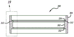
FIG. 19 is a detailed view of the region 19 shown in FIG. 16 of the lens casting gasket according to one embodiment of the present invention.
Figure 20 is a cross-sectional view of a functional wafer secured within a lens casting gasket by rotation of the wafer within the gasket according to one embodiment of the invention.
FIG. 21 is a detailed view of the region 21 shown in FIG. 20 of a portion of a lens casting gasket according to one embodiment of the invention.
Fig. 22 is a plan view of an optically functional wafer according to one embodiment of the present invention.
Figure 23 is a side view of an optically functional wafer according to one embodiment of the present invention.
Fig. 24 is a plan view of an optically functional wafer according to one embodiment of the present invention.
Fig. 25 is a plan view of an optically functional wafer according to one embodiment of the present invention.
Fig. 26 is a plan view of an optically functional wafer according to one embodiment of the present invention.
Fig. 27 is a plan view of an optically functional wafer according to one embodiment of the present invention.
Fig. 28 is a plan view of an optically functional wafer according to one embodiment of the present invention.
Fig. 29 is a plan view of an optically functional wafer according to one embodiment of the present invention.
Figure 30 is a plan view of an optically functional wafer according to one embodiment of the present invention.
Fig. 31 is a plan view of an optically functional wafer according to one embodiment of the present invention.
Fig. 32 is a plan view of an optically functional wafer according to one embodiment of the present invention.
Fig. 33 is a plan view of an optically functional wafer according to one embodiment of the present invention.
Detailed Description
Specific embodiments of the present invention will now be described with reference to the accompanying drawings. This invention may, however, be embodied in many different forms and should not be construed as limited to the embodiments set forth herein; rather, these embodiments are provided so that this disclosure will be thorough and complete, and will fully convey the scope of the invention to those skilled in the art. The terminology used in the detailed description of the embodiments illustrated in the accompanying drawings is not intended to be limiting of the invention. In the drawings, like numbering represents like elements.
Broadly speaking, the present invention provides a casting system and method that employs a casting assembly or gasket that allows for more efficient manual and/or automated loading of optical function wafers. In certain embodiments of the present invention, the inventive casting assembly is configured to receive wafers having a circular or non-circular shape. The benefits and improvements realized by the cast assembly of the present invention can be enhanced by employing complementary non-circular wafers that allow for easier loading into the gasket and/or better flow of the cast monomer around the wafers inserted into the gasket.
As shown in fig. 2-13, in some embodiments of the present invention, the cylindrical washer 100 employs a groove 112. A groove 112 is formed circumferentially inside the gasket 100 between a lower lip 120 and an upper lip 122 that protrude from the inner sidewall 102 of the gasket 100. The lower lip 120 forms a substantially continuous and/or uniform protrusion from the inner sidewall 102 of the gasket 100. The upper lip 122 forms an interrupted protrusion from the inner sidewall 102 of the gasket 100. Fig. 11 shows one form of cut 124 illustrating the discontinuity or interruption of the upper lip 122. The interrupted form of the upper lip 122 may additionally include asymmetric notches 126 and 128. The notches 126, for example, have a width that is greater than the width of the notches 128.
As shown in fig. 8, 12 and 13, the overall or general shape defined by the upper lip 122 is, for example, hexagonal. However, the hexagonal shape defined by the upper lip 122 in the drawings is only one example of the gasket 100, and the upper lip 122 of the gasket 100 may define other non-circular shapes that are complementary to the functional wafers described below.
In certain embodiments of the casting system of the present invention, the non-circular shape defined by the upper lip 122 of the gasket 100 is complementary to the shape and size of the optically functional wafer employed in the gasket 100 during cast lens formation. For example, with respect to the embodiment of the present invention as shown in fig. 2-13, a functional wafer 130 is employed having a form that is generally hexagonal in shape. Hexagonal wafers 130, as shown shaded in fig. 12, and certain advantages thereof, are described in more detail in assignee's U.S. patent application 14/616,606, the contents of which are incorporated herein by reference. As shown in fig. 24-33, and described in more detail below, in certain embodiments of the present invention, functional wafers that take the form of circles, ovals, rectangular shapes such as ribbon wafers, truncated circles, and asymmetrical and/or irregular shapes are employed in the gasket 100 and method of the present invention.
In some embodiments of the present invention, as shown in FIG. 13, the wafer 130 further employs asymmetric tabs 132 and 134 that protrude from different sides of the wafer 130. The tab 132 has, for example, a width greater than the width of the tab 134. The tabs 132 and 134 are shaped and sized complementary to the notches 128 and 126, respectively, of the upper lip 122 of the gasket 100. The asymmetry of the tabs 132 and 134 can help identify a desired orientation of the wafer 130 within the gasket 100. One or both of the tabs 132 and 134 of the wafer 130 may further serve as a grasping or handling point for the wafer 130 that is distinct from the bulk of the wafer 130, and/or may serve as a drop point during, for example, dip coating of the wafer 130.
As shown in fig. 12 and 13, the use of a gasket 100 having an upper lip 122 defining a hexagonal shape and a hexagonal wafer 130 or other non-circular shape provides significant advantages. For example, during assembly of the cast assembly, the wafers 130 are simply loaded into the gasket 100 by placing or seating the hexagonal wafers 130 within the hexagonal space defined by the upper lip 122 of the gasket 100. In the initial position of the wafer 130 in the gasket 100, the corners of the wafer are supported on the lower lip 120 of the gasket 100 at or below the notch 124 of the upper lip 122. Due to the complementary shape and size of the wafer 130 and the upper lip 122 of the gasket 110, the wafer 130 can be placed within the groove 112 of the gasket 100 with little or no handling or twisting of the wafer 130, thereby reducing the risk that the wafer 130 may be damaged during assembly of the cast gasket.
To secure the wafer 130 within the groove 112 of the gasket 100, the wafer 130 is rotated from an initial position within the groove 112. For example, as shown by comparing fig. 12 and 13, the wafer 130 may be rotated clockwise within the groove 112. As such, the corners of the hexagonal wafers 130 are located within the groove 112 between the lower lip 120 and the upper lip 122 of the gasket 100.
Due to the difference in the generally interrupted or irregular shape, such as the hexagonal shape of the wafer 130 and the generally circular shape of the lower lip 120 of the gasket 100, a space 136 is formed at the periphery of the portion of the wafer 130 between the periphery of the wafer 130 and the outer periphery of the lower lip 120. In part, the space 136 advantageously serves to facilitate the flow of a curable casting composition or monomer into the interior volume of the gasket 100 between the front face of the wafer 130 and the front lens mold surface.
One advantage of the casting system according to the present invention is the improved mechanical properties of the wafer or laminate structure 130 relative to PVA and/or PET films. The greater mechanical rigidity of the wafer 130 provides operational advantages in that it is less weak and/or less prone to warping during all processing steps, cutting, shaping and loading of the wafer 130 into the gasket. Loading the wafer 130 into the gasket is a less skilled process and is more acceptable to low skilled workers and/or automation. Furthermore, handling of wafer 130 with increased mechanical integrity is faster and more accurate. Once loaded onto the gasket 100, the wafer 130 is more rigid. Thus, during the filling process, wherein a curable casting composition or monomer is introduced into the assembled gasket 100, the monomer fills from the rear cavity and is allowed to flow therefrom to the front (narrower) cavity in less time under the influence of gravity.
In conventional casting processes, it is not possible to force the curable casting composition or monomer to flow faster (under pressure) because this distorts and displaces the typically relatively weak membrane. By employing the stronger wafer 130 of the present invention, the filling process can be accelerated because the structure of the wafer 130 can now withstand a certain degree of pressure without significant distortion of the wafer 130 in the gasket structure.
Employing the combination of the hexagonal upper lip 122 of the gasket 100 and the hexagonal wafer 130 formed at least in part from a thin film having increased structural integrity advantageously allows for semi-automation or full automation of the insert lens casting process. For example, if the wafer 130 is formed of a relatively strong, self-supporting material, a robot, such as a robot or robotic arm, may be employed to pick and place the wafer 130 into the gasket 100. For example, a robot employs a vacuum to pick a preformed hexagonal wafer 130 from a stock of wafers 130, inserts the wafer 130 into the hexagonal shape defined by the upper lip 122 of the gasket 100, secures the wafer 130 within the groove 112 of the gasket 100 by rotating the wafer 130, and releases the vacuum to release the wafer 130.
In other words, the use of hexagonal wafers 130 in the casting system of the present invention allows the wafers 130 to be held securely in place during the mold filling and lens curing process using a rotational locking method, also known as a snap fit (Bayonet Style Fitting). The hexagonal cut wafer 130 (flat or pre-shaped with a lens curvature) may be "dropped" into a specific opening in the gasket 100 and rotated in a range of 10 to 60 degrees, for example 30 degrees, around the center of the wafer 130 to effectively lock in place and prevent movement of the wafer 130 within the gasket 100 during the casting process. In this manner, the process is easily automated, thereby eliminating or reducing the need for skilled and time-consuming labor required in conventional wafer-gasket assembly processes. Accordingly, the present invention is a significant advancement in casting technology.
Further, it should be noted that by using hexagonal wafers 130, distortion of wafers 130 is eliminated or at least reduced during loading into gasket 100 as compared to known casting processes. As previously mentioned, in conventional casting systems, the film is typically severely distorted during assembly of the cast gasket. Depending on the degree of distortion, lenses formed with distorted wafers are increasingly likely to contain unacceptable defects resulting in low production efficiency.
The casting system of the present invention also provides at least the following advantages over known casting systems. First, the washer 100 can be used to secure a quasi-circular or ribbon wafer without the use of a rotational retaining feature. Second, the present casting system reduces contact points while maintaining the structural integrity of the wafer. Third, the present casting system facilitates placement of the wafer in the gasket, thereby achieving operational efficiency. Fourth, the hexagonal wafer 130 may be used with a more conventional round cast washer. The hexagonal shape of the wafer 130 facilitates faster assembly of the wafer into the gasket process, which traditionally requires skilled labor and significant time.
Fifth, the addition of tabs 132 and 134 and the drip/kiss feature of wafer 130 allows wafer 130 to be uniformly coated in, for example, a liquid curing adhesive (used to ensure that the wafer adheres to curable compositions or monomers) without optical distortion at the major wafer surface that would otherwise damage the optical surface. In fig. 13, the dip/kiss protrusions (tabs 132 and 134) are shown at the 12 o 'clock and 6 o' clock positions of the locked wafer position. One of the tabs 132 and 134 is used to hold or manipulate the wafer while the other tab is used to remove a drop of liquid applied (impregnated) adhesive.
In another embodiment of the present invention, as shown in fig. 14-19, the cylindrical washer 300 employs grooves 312 to insert and hold the wafer during lens casting. A groove 312 is formed circumferentially in the interior of the washer 300 between an upper side 324 of the lower lip 320 and a lower side 330 of the upper lip 322 formed on the inner sidewall 302 of the washer 300. In this embodiment, the lower lip 320 and the upper lip 322 each form a substantially continuous and/or uniform protrusion from the inner sidewall 302 of the gasket 300.
The recess 312 employs recess sidewalls 336 that are substantially parallel to the sides of the gasket 300. The height and diameter of the groove sidewalls 336 depend on the diameter and thickness of the wafer used to form the cast lens. For example, for a wafer having a maximum diameter or dimension of 79.5 millimeters, the groove sidewalls 336 can have a diameter in the range of 80 to 81 millimeters, such as 80.5 millimeters. In other words, the diameter of the pocket sidewall 336 of the gasket 300 will be slightly larger than the largest diameter or dimension of the wafer employed in the corresponding gasket by about 0.2 to 0.3 millimeters. For a wafer having a laminate or film thickness of about 0.6 millimeters, the groove sidewalls 336 will have a height in the range of 0.2 to 1.0 millimeters, such as 0.6 millimeters.
The underside of upper lip 330 extends from groove sidewall 336 at an angle in the range of 105 to 165 degrees (e.g., about 135 degrees) relative to groove sidewall 336. The upper side 324 of the lower lip 320 extends from the groove sidewall 336 at an angle in the range of 75 to 105 degrees (e.g., about 90 degrees) relative to the groove sidewall 336. Thus, as shown in fig. 16, 17 and 19, the underside of upper lip 330 and the upper side 324 of lower lip 320 provide a tapered sidewall profile to groove 312.
In most cast lens applications, the wafer employed in the groove 312 will be formed to have a spherical or aspherical curvature. Thus, the effective thickness of the formed wafer will be greater than the actual laminate or film thickness of the wafer. In view of the slightly oversized diameter of the groove sidewalls 336 described above, the shaped wafer employed within the groove 312 of the gasket 300 is held in place within the groove 312 primarily by a clamping or friction fit with the tapered sidewall profile of the groove 312. As described in more detail below, all or only a portion of the periphery of the wafer may be clamped or friction fit with the tapered sidewall profile of the recess 312, depending on the shape of the periphery of the wafer employed.
The upper side 328 of the upper lip 322 forms a front mold stop or rim 334 and an opposing stop for the back mold is formed by a back mold stop or rim 332. It should be understood that the shape of the front mold stop or rim 334 and the shape of the rear mold stop or rim 332 may vary depending on the respective shapes of the front and rear molds employed in the assembled gasket 300. The rear interior volume of the assembled gasket 300, i.e., the diameter and height or size of the gasket between the groove 312 and the rear mold stop or rim 322, will vary depending on the desired configuration of the cast lens. For example, in some embodiments, the size of the gasket between the groove 312 and the posterior mold stop or rim 332 is in the range of 7.0 to 12.5 millimeters, such as 7.3 or 12.1 millimeters.
In certain embodiments, the gasket 300 according to the present invention employs a fill port 318 and a vent port 340. As shown in fig. 14, 17 and 18, the fill port 318 passes substantially perpendicularly through the outer sidewall 304 of the gasket 312 between the groove 312 and the posterior mold stop or rim 332 toward the inner sidewall 302 of the gasket 312. Thus, during the formation of a cast lens according to the present invention, the curable casting composition or monomer will first enter and begin to fill the interior space of the assembled gasket 300 on the back side of the wafer (i.e., between the concave surface of the formed wafer and the convex surface of the back mold). The fill port 318 may, but need not, employ a 1.0 millimeter 45 degree chamfered edge or entrance on the outer sidewall 304 of the gasket 300. The fill port 318 may have a generally circular or non-circular shape. The diameter or maximum cross-sectional dimension of the fill port 318 is in the range of 2 to 6 millimeters, such as 4 millimeters.
As shown in fig. 14, 17 and 18, the vent 340 passes substantially perpendicularly through the outer sidewall 304 of the gasket 312 between the anterior mold stop or rim 334 and the upper side 324 of the lower lip 320 of the groove 312 to the inner sidewall 302 of the gasket 312. In other words, the exhaust port is formed through the side of the gasket 300 at an area or point that coincides, substantially coincides, or intersects with the groove 312. Thus, the exhaust port 340 forms an interruption in the otherwise continuous and/or uniform projection of the upper lip 322 of the groove from the inner sidewall 302 of the gasket 300. The fill port 340 may have a circular or oblong, e.g., elliptical, cross-sectional shape with a diameter or maximum cross-sectional dimension in the range of 0.5 to 6 millimeters, e.g., 2 or 4 millimeters.
In certain embodiments, gasket 300 according to the present disclosure may, but need not, employ fill port chamber 342 and/or vent port chamber 344. The fill port chamber 342 and the vent port chamber 344 may have any general form, such as a box or cylindrical form. In certain embodiments, as shown in fig. 14, 15 and 17, the fill port chamber 342 and the vent port chamber 344 are formed in a common or shared structure, such as a chamber box 348, and are separated from each other by a wall 346. The chamber box has dimensions in the following ranges: 20 to 30 mm, for example 22 or 27.1 mm wide; 37 to 57 mm, for example 47 mm long; and 6 to 16 mm, for example 11 mm high. As shown in fig. 14, 15, 17, and 18, in some embodiments the gasket and the chamber housing 348 are connected to each other by a chamber manifold 350, the chamber manifold 350 being formed to narrow from a bottom 352 of the chamber housing 348 to the fill port 318 and the vent port 340.
The fill port chamber 342 serves to capture and/or retain excess curable casting composition or monomer that may exit the curable casting composition or monomer source nozzle and thereby provide additional curable casting composition or monomer to enter the assembled gasket and compensate for shrinkage of the curable casting composition or monomer within the assembled gasket when the gasket and source nozzle are separated. The vent chamber 344 is used to capture and/or hold excess curable foundry composition or monomer that may exit the vent 340 as the assembled gasket is filled and thereby provide a source of curable foundry composition or monomer to enter the assembled gasket and compensate for shrinkage of the curable foundry composition or monomer within the assembled gasket during curing or gelation of the curable foundry composition or monomer. The vent chamber 344 also serves to prevent air from entering the gasket during filling of the assembled gasket with the curable casting composition or monomer.
In some embodiments of the present invention, the gasket 300 employs a fill port tube 354, the fill port tube 354 extending from the fill port 318 on the outer sidewall 304 of the gasket 300. The fill lumen 356 of the fill port cylinder 354 has a diameter or maximum cross-sectional dimension in the range of 2 to 6 millimeters, such as 4 millimeters. The diameter and or elasticity of the material forming the fill port cylinder 354 allows the internal cavity 356 of the fill port cylinder 354 to receive a curable casting composition or monomer source nozzle 358 during filling of the gasket 300 with the curable casting composition or monomer. The fill port cylinder 354 has a length in the range of 5 to 15 millimeters, such as 10 millimeters. The fill port cylinder 354 is used, in part, to trap or trap air bubbles that may form and enter the gasket as the source nozzle 358 is withdrawn from the gasket 300 during filling of the gasket with a curable casting composition or monomer. The vent chamber 344 also serves to prevent air from entering the gasket during filling of the assembled gasket with the curable casting composition or monomer. Fill port cylinder 354 also serves in part to prevent air from entering the gasket during filling of the assembled gasket with the curable casting composition or monomer. The fill port cylinder 354 may be employed on the gasket 300 as a separate feature extending from the fill port 318 or between the fill port chamber 342 and the fill port 318.
In certain embodiments of the present invention, the gasket 100 previously described may also employ any or all of the above-described fill and vent features, including the fill port chamber 342, the vent port chamber 344, the chamber housing 348, the chamber housing manifold 350, and the fill port cylinder 554.
In a further embodiment of the present invention, a wafer optimized for use with the above-described gaskets 100 and/or 300 is provided. In a first wafer embodiment, a wafer 400 having an irregular hexagonal shape is provided. As shown in fig. 22 and 23, the wafer 400 has five straight or substantially straight sides 402 and one curved or rounded side 404. Curved side 404 of wafer 400 has a radius of, for example, 39.75 degrees. The intersections between the straight sides 402 and the curved sides 404 are rounded. The wafer 400 has a maximum dimension or diameter 406 of, for example, 79.5 + -0.2 millimeters and a dimension between opposing straight sides 404 of, for example, 74.5 + -0.3 millimeters. In some embodiments, wafer 400 has a lamination or film thickness of about 0.6 ± 0.3 millimeters. In certain embodiments, once the wafer 400 has been formed to, for example, 2.3 diopters, the diameter 406 of the wafer 400 is, for example, 77 ± 0.3 millimeters.
When used in gasket 300, the curved side 304 of wafer 400 is positioned against vent 340. In this orientation, the straight side 402 provides a gap or hole between the periphery of the wafer 400 and the groove 312 of the gasket 300 that allows the flow of the curable casting composition or monomer from the back side of the wafer where the fill port 318 is located to the interior volume of the gasket between the front convex side of the wafer 400 and the concave side of the front mold. The positioning of the curved side 304 of the wafer 400 against the vent 340 advantageously provides for improved venting or venting of the internal gases of the gasket 300 during filling of the gasket 300 with a curable casting composition or monomer.
In methods employing the gasket 300 and the wafer 400 or any other of the above and below described wafers of the invention, an operator first inserts, for example, the optically functional wafer 300 into the recess 312 such that the curved side 404 abuts or covers the vent 340 of the gasket 300. Next, the operator inserts the front and rear molds at respective positions of the front mold stop 334 and the rear mold stop 332 against the gasket 300. The operator would then mate the source nozzle 358 with the fill port 318 by, for example, inserting the source nozzle 358 into the interior cavity 356 of the fill port cylinder 354 or by inserting the source nozzle 358 directly into the fill port 318 and begin filling the interior of the assembled gasket with the curable casting composition or monomer. In view of the location of the fill port 318 on the back side of the wafer 300, the filling of the interior volume of the gasket between the back mold and the back side of the wafer 300 begins first. As the content of the curable casting composition or monomer increases, the curable casting composition or monomer begins to flow around the periphery of the wafer 300 into the interior volume of the gasket formed in front of the front mold and the wafer 300.
Due to this continuous filling and the novel location of the vent 340 coincident with the groove 312, air or gas displaced by the curable casting composition or monomer from within the assembled gasket is effectively vented out of the vent 312 and not trapped within the assembled gasket 300. Once the assembled gasket is filled with the curable casting composition or monomer, the operator separates the source nozzle 358 from the fill port 318 and continues to allow the curable casting composition or monomer within the gasket to gel and fully cure, for example, upon application of heat or ultraviolet radiation.
In certain embodiments of the casting system of the present invention, the optically functional wafer employed in gasket 100 and/or 300 during the formation of the cast lens is formed from one or more layers of transparent film having a structural integrity about equal to or greater than that of, for example, known PVA-based wafers. The optically functional wafer used in the gasket of the present invention during cast lens formation is formed, for example, from one or more layers of polycarbonate, polyester, polyethylene terephthalate, triacetate, or cellulose triacetate, or a combination thereof. The optically functional wafer used in the gasket of the present invention during cast lens formation has a thickness of 3 to 0.1 mm, for example 2.0 mm, 1.0 mm, 0.5 mm or 0.6 mm.
In certain embodiments of the present invention, the wafer may be treated or coated to impart additional properties or optical functionality or to impart chemical resistance to the curable casting composition or monomer prior to use in the casting process of the present invention. For example, when a wafer is formed from one or more polycarbonate films or layers, a hardcoat may be applied to the surface of the polycarbonate that will be in direct contact with the curable casting composition or monomer. Such a hard coating serves to protect the polycarbonate from the effects of chemical attack by the casting monomer and/or as a binder. Alternatively or additionally, the wafer may be coated with a layer of a water-based aliphatic polycarbonate polyurethane dispersion (PUD) adhesive, such as PU400(Stahl Polymer). Additional details regarding such wafers and the processing thereof are disclosed in assignee's U.S. patent application 13/741,290, the contents of which are incorporated herein by reference.
As used in this disclosure, the term optically functional wafer is intended to mean a single layer thin film wafer or a multilayer thin film laminate wafer that includes optically functional properties. The optically functional characteristic or property includes filtering or attenuating, decorative, and/or durability features of light or other radiation, which are incorporated into an optical lens to impart or modify lens characteristics other than optical power or magnification characteristics. Non-limiting examples of specific functional characteristics or properties include light polarization, photochromism, electrochromism, coloration, color, hardness, chemical resistance, and reflectivity.
Fig. 24 to 32 show alternative embodiments of a functional wafer according to the invention. In fig. 24 to 32, the symbol "R" indicates that the value immediately following is the radius of the indicated wafer portion. Each of the wafers shown in fig. 24-32 employs at least two distinct sections. The first portion is defined by at least one first continuous curve having a first radius, and the second portion is formed by at least one straight line or one curve having a second radius different from the first radius of the first portion.
In certain embodiments of the present invention, the cast gasket and wafer described above are employed to form a cast lens formed from a curable casting composition or monomer, and more particularly, from a composition employing a liquid monomer mixture or a polyurethane-based polymer composition. These materials include, but are not limited to, polymers based on allyl diglycol carbonate monomers (e.g., CR-39 available from PPG Industries, Inc.; MR series monomers from Mitsui chemicals (MR-7, MR-10, MR-95, MR174, etc.) based on polyisocyanate polythiol monomers; polyurethane-based prepolymer compositions (e.g., Trivex, PPG), and polycarbonates (e.g., LEXAN available from General Electric Co.).
Although the present invention has been described in terms of particular embodiments and applications, those of ordinary skill in the art, in light of this teaching, can generate additional embodiments and modifications without departing from the spirit of or exceeding the scope of the claimed invention. Accordingly, it is to be understood that the drawings and descriptions herein are proffered by way of example to facilitate comprehension of the invention and should not be construed to limit the scope thereof.
Claims (18)
Priority Applications (1)
| Application Number | Priority Date | Filing Date | Title |
|---|---|---|---|
| CN202110907969.7A CN113618989B (en) | 2015-12-14 | 2016-12-14 | Lens casting system |
Applications Claiming Priority (3)
| Application Number | Priority Date | Filing Date | Title |
|---|---|---|---|
| US201562267178P | 2015-12-14 | 2015-12-14 | |
| US62/267,178 | 2015-12-14 | ||
| PCT/US2016/066695 WO2017106371A1 (en) | 2015-12-14 | 2016-12-14 | Lens casting system |
Related Child Applications (1)
| Application Number | Title | Priority Date | Filing Date |
|---|---|---|---|
| CN202110907969.7A Division CN113618989B (en) | 2015-12-14 | 2016-12-14 | Lens casting system |
Publications (2)
| Publication Number | Publication Date |
|---|---|
| CN108602210A CN108602210A (en) | 2018-09-28 |
| CN108602210B true CN108602210B (en) | 2021-08-31 |
Family
ID=59019293
Family Applications (2)
| Application Number | Title | Priority Date | Filing Date |
|---|---|---|---|
| CN201680080116.8A Active CN108602210B (en) | 2015-12-14 | 2016-12-14 | Lens Casting System |
| CN202110907969.7A Active CN113618989B (en) | 2015-12-14 | 2016-12-14 | Lens casting system |
Family Applications After (1)
| Application Number | Title | Priority Date | Filing Date |
|---|---|---|---|
| CN202110907969.7A Active CN113618989B (en) | 2015-12-14 | 2016-12-14 | Lens casting system |
Country Status (3)
| Country | Link |
|---|---|
| US (3) | US10926434B2 (en) |
| CN (2) | CN108602210B (en) |
| WO (1) | WO2017106371A1 (en) |
Families Citing this family (3)
| Publication number | Priority date | Publication date | Assignee | Title |
|---|---|---|---|---|
| CN108602210B (en) * | 2015-12-14 | 2021-08-31 | 视觉缓解公司 | Lens Casting System |
| TWI755595B (en) * | 2019-05-06 | 2022-02-21 | 上暘光學股份有限公司 | The protruding structure of the lens barrel |
| EP3838539A1 (en) * | 2019-12-17 | 2021-06-23 | Essilor International | Methods, apparatuses, and systems for a wafer having a viscoelastic material |
Family Cites Families (16)
| Publication number | Priority date | Publication date | Assignee | Title |
|---|---|---|---|---|
| FR2416104A1 (en) * | 1978-02-07 | 1979-08-31 | Essilor Int | MOLDING DEVICE, IN PARTICULAR FOR SOFT CONTACT LENS |
| US4238540A (en) * | 1979-05-29 | 1980-12-09 | Celanese Corporation | Fiber reinforced composite shaft with metallic connector sleeves mounted by connector ring interlock |
| US4227673A (en) | 1979-08-10 | 1980-10-14 | American Optical Corporation | Gasket for casting lenses |
| US4693446A (en) * | 1985-09-20 | 1987-09-15 | Techna Vision, Inc. | Gasket for molding plastic lenses |
| US5286419A (en) * | 1992-02-20 | 1994-02-15 | Bmc Industries, Inc. | Process for making a light polarizing spectacle lens |
| US6787070B2 (en) | 1998-02-19 | 2004-09-07 | Technology Resource International Corp. | Apparatus and method of filling a mold for manufacturing an ophthalmic lens |
| CA2337124A1 (en) * | 1998-07-24 | 2000-02-03 | Duane L. Wires | Method and compositions for manufacturing coated photochromatic articles |
| US6391231B1 (en) * | 1998-11-23 | 2002-05-21 | Younger Mfg. Co. | Method for side-fill lens casting |
| US20040188873A1 (en) * | 2001-07-16 | 2004-09-30 | Kotaro Ono | Method for producing resin lens and the resin lens |
| US20060103037A1 (en) | 2004-11-18 | 2006-05-18 | Kai Su | Disposable molds and method of using the same |
| US20060103041A1 (en) * | 2004-11-18 | 2006-05-18 | Kai Su | Molds and method of using the same for forming plus or minus lenses |
| FR2893423B1 (en) * | 2005-11-15 | 2007-12-21 | Bnl Eurolens Soc Par Actions S | EYEBAR WITH INSERT AND METHOD OF MANUFACTURING THE SAME |
| US8792180B2 (en) * | 2009-06-12 | 2014-07-29 | Konica Minolta Opto, Inc. | Production method of wafer lens, intermediate die, optical component, molding die, and production method of molding die |
| CN103240828B (en) * | 2013-05-09 | 2015-04-01 | 李亨群 | Mould for resin lens |
| CN114131971B (en) * | 2014-02-07 | 2024-08-20 | 豪雅光学实验室(美国)股份有限公司 | Cutting pattern of film |
| CN108602210B (en) * | 2015-12-14 | 2021-08-31 | 视觉缓解公司 | Lens Casting System |
-
2016
- 2016-12-14 CN CN201680080116.8A patent/CN108602210B/en active Active
- 2016-12-14 CN CN202110907969.7A patent/CN113618989B/en active Active
- 2016-12-14 US US15/379,287 patent/US10926434B2/en active Active
- 2016-12-14 WO PCT/US2016/066695 patent/WO2017106371A1/en not_active Ceased
-
2021
- 2021-01-22 US US17/155,755 patent/US12017388B2/en active Active
-
2024
- 2024-05-21 US US18/670,517 patent/US20240308115A1/en active Pending
Also Published As
| Publication number | Publication date |
|---|---|
| US20170165878A1 (en) | 2017-06-15 |
| US20210138694A1 (en) | 2021-05-13 |
| WO2017106371A1 (en) | 2017-06-22 |
| CN113618989A (en) | 2021-11-09 |
| US10926434B2 (en) | 2021-02-23 |
| US12017388B2 (en) | 2024-06-25 |
| US20240308115A1 (en) | 2024-09-19 |
| CN113618989B (en) | 2023-08-01 |
| CN108602210A (en) | 2018-09-28 |
Similar Documents
| Publication | Publication Date | Title |
|---|---|---|
| US20240308115A1 (en) | Lens Casting System | |
| US6391231B1 (en) | Method for side-fill lens casting | |
| US20250208439A1 (en) | Ophthalmic lens with graded microlenses | |
| CN103930808B (en) | Spreadlight lens and its manufacturing method | |
| JP6207622B2 (en) | Manufacturing method of polarizing lens for eyewear | |
| US10267966B2 (en) | Composite functional polarized lens | |
| US7758332B2 (en) | Axis control in toric contact lens production | |
| US20130224440A1 (en) | Flexible film with surface relief and use thereof in electro-active optical systems | |
| WO2013074269A1 (en) | 3d lenses and methods of making the same | |
| WO2019230884A1 (en) | Polarizing film, method for molding polarizing film, and method for manufacturing polarizing lens | |
| CN112368136B (en) | Improved forming device for casting an optical product with a thin sheet on top, corresponding method, and optical product | |
| JPS6226289B2 (en) | ||
| US11878480B2 (en) | Wafer holder band for mold injection process | |
| US20220404643A1 (en) | Stabilized Thin Lens | |
| EP3770663B1 (en) | Lens system, method for manufacturing space ring, and method for assembling lens system | |
| JP2004237649A (en) | Short-term manufacturing method of polyamide polarizing optical lens | |
| US9616598B2 (en) | Plastic lens manufacturing method | |
| EP4371750A1 (en) | Polarizing pva wafer for reducing optical distortion | |
| HK1160418B (en) | Molding for optical purposes, particularly filter ring or lens holder | |
| HK1125071B (en) | Axis control in toric contact lens production | |
| HK1160418A1 (en) | Molding for optical purposes, particularly filter ring or lens holder |
Legal Events
| Date | Code | Title | Description |
|---|---|---|---|
| PB01 | Publication | ||
| PB01 | Publication | ||
| SE01 | Entry into force of request for substantive examination | ||
| SE01 | Entry into force of request for substantive examination | ||
| GR01 | Patent grant | ||
| GR01 | Patent grant | ||
| TR01 | Transfer of patent right | ||
| TR01 | Transfer of patent right |
Effective date of registration: 20230904 Address after: Texas, USA Patentee after: Haoya Optical Laboratory (USA) Co.,Ltd. Address before: Minn Patentee before: VISION EASE, L.P. |