CN108473391B - Process for improving propylene recovery of FCC recovery units - Google Patents
Process for improving propylene recovery of FCC recovery units Download PDFInfo
- Publication number
- CN108473391B CN108473391B CN201680073279.3A CN201680073279A CN108473391B CN 108473391 B CN108473391 B CN 108473391B CN 201680073279 A CN201680073279 A CN 201680073279A CN 108473391 B CN108473391 B CN 108473391B
- Authority
- CN
- China
- Prior art keywords
- stream
- liquid
- propylene
- gas
- iii
- Prior art date
- Legal status (The legal status is an assumption and is not a legal conclusion. Google has not performed a legal analysis and makes no representation as to the accuracy of the status listed.)
- Active
Links
Images


Classifications
-
- C—CHEMISTRY; METALLURGY
- C10—PETROLEUM, GAS OR COKE INDUSTRIES; TECHNICAL GASES CONTAINING CARBON MONOXIDE; FUELS; LUBRICANTS; PEAT
- C10G—CRACKING HYDROCARBON OILS; PRODUCTION OF LIQUID HYDROCARBON MIXTURES, e.g. BY DESTRUCTIVE HYDROGENATION, OLIGOMERISATION, POLYMERISATION; RECOVERY OF HYDROCARBON OILS FROM OIL-SHALE, OIL-SAND, OR GASES; REFINING MIXTURES MAINLY CONSISTING OF HYDROCARBONS; REFORMING OF NAPHTHA; MINERAL WAXES
- C10G11/00—Catalytic cracking, in the absence of hydrogen, of hydrocarbon oils
- C10G11/14—Catalytic cracking, in the absence of hydrogen, of hydrocarbon oils with preheated moving solid catalysts
- C10G11/18—Catalytic cracking, in the absence of hydrogen, of hydrocarbon oils with preheated moving solid catalysts according to the "fluidised-bed" technique
-
- B—PERFORMING OPERATIONS; TRANSPORTING
- B01—PHYSICAL OR CHEMICAL PROCESSES OR APPARATUS IN GENERAL
- B01D—SEPARATION
- B01D1/00—Evaporating
- B01D1/16—Evaporating by spraying
- B01D1/20—Sprayers
-
- B—PERFORMING OPERATIONS; TRANSPORTING
- B01—PHYSICAL OR CHEMICAL PROCESSES OR APPARATUS IN GENERAL
- B01D—SEPARATION
- B01D3/00—Distillation or related exchange processes in which liquids are contacted with gaseous media, e.g. stripping
- B01D3/06—Flash distillation
-
- B—PERFORMING OPERATIONS; TRANSPORTING
- B01—PHYSICAL OR CHEMICAL PROCESSES OR APPARATUS IN GENERAL
- B01D—SEPARATION
- B01D5/00—Condensation of vapours; Recovering volatile solvents by condensation
-
- B—PERFORMING OPERATIONS; TRANSPORTING
- B01—PHYSICAL OR CHEMICAL PROCESSES OR APPARATUS IN GENERAL
- B01D—SEPARATION
- B01D53/00—Separation of gases or vapours; Recovering vapours of volatile solvents from gases; Chemical or biological purification of waste gases, e.g. engine exhaust gases, smoke, fumes, flue gases, aerosols
- B01D53/002—Separation of gases or vapours; Recovering vapours of volatile solvents from gases; Chemical or biological purification of waste gases, e.g. engine exhaust gases, smoke, fumes, flue gases, aerosols by condensation
-
- C—CHEMISTRY; METALLURGY
- C10—PETROLEUM, GAS OR COKE INDUSTRIES; TECHNICAL GASES CONTAINING CARBON MONOXIDE; FUELS; LUBRICANTS; PEAT
- C10G—CRACKING HYDROCARBON OILS; PRODUCTION OF LIQUID HYDROCARBON MIXTURES, e.g. BY DESTRUCTIVE HYDROGENATION, OLIGOMERISATION, POLYMERISATION; RECOVERY OF HYDROCARBON OILS FROM OIL-SHALE, OIL-SAND, OR GASES; REFINING MIXTURES MAINLY CONSISTING OF HYDROCARBONS; REFORMING OF NAPHTHA; MINERAL WAXES
- C10G11/00—Catalytic cracking, in the absence of hydrogen, of hydrocarbon oils
-
- C—CHEMISTRY; METALLURGY
- C10—PETROLEUM, GAS OR COKE INDUSTRIES; TECHNICAL GASES CONTAINING CARBON MONOXIDE; FUELS; LUBRICANTS; PEAT
- C10G—CRACKING HYDROCARBON OILS; PRODUCTION OF LIQUID HYDROCARBON MIXTURES, e.g. BY DESTRUCTIVE HYDROGENATION, OLIGOMERISATION, POLYMERISATION; RECOVERY OF HYDROCARBON OILS FROM OIL-SHALE, OIL-SAND, OR GASES; REFINING MIXTURES MAINLY CONSISTING OF HYDROCARBONS; REFORMING OF NAPHTHA; MINERAL WAXES
- C10G70/00—Working-up undefined normally gaseous mixtures obtained by processes covered by groups C10G9/00, C10G11/00, C10G15/00, C10G47/00, C10G51/00
- C10G70/04—Working-up undefined normally gaseous mixtures obtained by processes covered by groups C10G9/00, C10G11/00, C10G15/00, C10G47/00, C10G51/00 by physical processes
- C10G70/041—Working-up undefined normally gaseous mixtures obtained by processes covered by groups C10G9/00, C10G11/00, C10G15/00, C10G47/00, C10G51/00 by physical processes by distillation
-
- C—CHEMISTRY; METALLURGY
- C10—PETROLEUM, GAS OR COKE INDUSTRIES; TECHNICAL GASES CONTAINING CARBON MONOXIDE; FUELS; LUBRICANTS; PEAT
- C10G—CRACKING HYDROCARBON OILS; PRODUCTION OF LIQUID HYDROCARBON MIXTURES, e.g. BY DESTRUCTIVE HYDROGENATION, OLIGOMERISATION, POLYMERISATION; RECOVERY OF HYDROCARBON OILS FROM OIL-SHALE, OIL-SAND, OR GASES; REFINING MIXTURES MAINLY CONSISTING OF HYDROCARBONS; REFORMING OF NAPHTHA; MINERAL WAXES
- C10G70/00—Working-up undefined normally gaseous mixtures obtained by processes covered by groups C10G9/00, C10G11/00, C10G15/00, C10G47/00, C10G51/00
- C10G70/04—Working-up undefined normally gaseous mixtures obtained by processes covered by groups C10G9/00, C10G11/00, C10G15/00, C10G47/00, C10G51/00 by physical processes
- C10G70/043—Working-up undefined normally gaseous mixtures obtained by processes covered by groups C10G9/00, C10G11/00, C10G15/00, C10G47/00, C10G51/00 by physical processes by fractional condensation
-
- C—CHEMISTRY; METALLURGY
- C10—PETROLEUM, GAS OR COKE INDUSTRIES; TECHNICAL GASES CONTAINING CARBON MONOXIDE; FUELS; LUBRICANTS; PEAT
- C10L—FUELS NOT OTHERWISE PROVIDED FOR; NATURAL GAS; SYNTHETIC NATURAL GAS OBTAINED BY PROCESSES NOT COVERED BY SUBCLASSES C10G OR C10K; LIQUIFIED PETROLEUM GAS; USE OF ADDITIVES TO FUELS OR FIRES; FIRE-LIGHTERS
- C10L3/00—Gaseous fuels; Natural gas; Synthetic natural gas obtained by processes not covered by subclass C10G, C10K; Liquefied petroleum gas
- C10L3/12—Liquefied petroleum gas
-
- C—CHEMISTRY; METALLURGY
- C10—PETROLEUM, GAS OR COKE INDUSTRIES; TECHNICAL GASES CONTAINING CARBON MONOXIDE; FUELS; LUBRICANTS; PEAT
- C10G—CRACKING HYDROCARBON OILS; PRODUCTION OF LIQUID HYDROCARBON MIXTURES, e.g. BY DESTRUCTIVE HYDROGENATION, OLIGOMERISATION, POLYMERISATION; RECOVERY OF HYDROCARBON OILS FROM OIL-SHALE, OIL-SAND, OR GASES; REFINING MIXTURES MAINLY CONSISTING OF HYDROCARBONS; REFORMING OF NAPHTHA; MINERAL WAXES
- C10G2300/00—Aspects relating to hydrocarbon processing covered by groups C10G1/00 - C10G99/00
- C10G2300/10—Feedstock materials
- C10G2300/1037—Hydrocarbon fractions
- C10G2300/104—Light gasoline having a boiling range of about 20 - 100 °C
-
- C—CHEMISTRY; METALLURGY
- C10—PETROLEUM, GAS OR COKE INDUSTRIES; TECHNICAL GASES CONTAINING CARBON MONOXIDE; FUELS; LUBRICANTS; PEAT
- C10G—CRACKING HYDROCARBON OILS; PRODUCTION OF LIQUID HYDROCARBON MIXTURES, e.g. BY DESTRUCTIVE HYDROGENATION, OLIGOMERISATION, POLYMERISATION; RECOVERY OF HYDROCARBON OILS FROM OIL-SHALE, OIL-SAND, OR GASES; REFINING MIXTURES MAINLY CONSISTING OF HYDROCARBONS; REFORMING OF NAPHTHA; MINERAL WAXES
- C10G2300/00—Aspects relating to hydrocarbon processing covered by groups C10G1/00 - C10G99/00
- C10G2300/10—Feedstock materials
- C10G2300/1037—Hydrocarbon fractions
- C10G2300/1044—Heavy gasoline or naphtha having a boiling range of about 100 - 180 °C
-
- C—CHEMISTRY; METALLURGY
- C10—PETROLEUM, GAS OR COKE INDUSTRIES; TECHNICAL GASES CONTAINING CARBON MONOXIDE; FUELS; LUBRICANTS; PEAT
- C10G—CRACKING HYDROCARBON OILS; PRODUCTION OF LIQUID HYDROCARBON MIXTURES, e.g. BY DESTRUCTIVE HYDROGENATION, OLIGOMERISATION, POLYMERISATION; RECOVERY OF HYDROCARBON OILS FROM OIL-SHALE, OIL-SAND, OR GASES; REFINING MIXTURES MAINLY CONSISTING OF HYDROCARBONS; REFORMING OF NAPHTHA; MINERAL WAXES
- C10G2300/00—Aspects relating to hydrocarbon processing covered by groups C10G1/00 - C10G99/00
- C10G2300/10—Feedstock materials
- C10G2300/1088—Olefins
-
- C—CHEMISTRY; METALLURGY
- C10—PETROLEUM, GAS OR COKE INDUSTRIES; TECHNICAL GASES CONTAINING CARBON MONOXIDE; FUELS; LUBRICANTS; PEAT
- C10G—CRACKING HYDROCARBON OILS; PRODUCTION OF LIQUID HYDROCARBON MIXTURES, e.g. BY DESTRUCTIVE HYDROGENATION, OLIGOMERISATION, POLYMERISATION; RECOVERY OF HYDROCARBON OILS FROM OIL-SHALE, OIL-SAND, OR GASES; REFINING MIXTURES MAINLY CONSISTING OF HYDROCARBONS; REFORMING OF NAPHTHA; MINERAL WAXES
- C10G2400/00—Products obtained by processes covered by groups C10G9/00 - C10G69/14
- C10G2400/20—C2-C4 olefins
-
- C—CHEMISTRY; METALLURGY
- C10—PETROLEUM, GAS OR COKE INDUSTRIES; TECHNICAL GASES CONTAINING CARBON MONOXIDE; FUELS; LUBRICANTS; PEAT
- C10L—FUELS NOT OTHERWISE PROVIDED FOR; NATURAL GAS; SYNTHETIC NATURAL GAS OBTAINED BY PROCESSES NOT COVERED BY SUBCLASSES C10G OR C10K; LIQUIFIED PETROLEUM GAS; USE OF ADDITIVES TO FUELS OR FIRES; FIRE-LIGHTERS
- C10L2290/00—Fuel preparation or upgrading, processes or apparatus therefore, comprising specific process steps or apparatus units
- C10L2290/06—Heat exchange, direct or indirect
-
- C—CHEMISTRY; METALLURGY
- C10—PETROLEUM, GAS OR COKE INDUSTRIES; TECHNICAL GASES CONTAINING CARBON MONOXIDE; FUELS; LUBRICANTS; PEAT
- C10L—FUELS NOT OTHERWISE PROVIDED FOR; NATURAL GAS; SYNTHETIC NATURAL GAS OBTAINED BY PROCESSES NOT COVERED BY SUBCLASSES C10G OR C10K; LIQUIFIED PETROLEUM GAS; USE OF ADDITIVES TO FUELS OR FIRES; FIRE-LIGHTERS
- C10L2290/00—Fuel preparation or upgrading, processes or apparatus therefore, comprising specific process steps or apparatus units
- C10L2290/30—Pressing, compressing or compacting
-
- C—CHEMISTRY; METALLURGY
- C10—PETROLEUM, GAS OR COKE INDUSTRIES; TECHNICAL GASES CONTAINING CARBON MONOXIDE; FUELS; LUBRICANTS; PEAT
- C10L—FUELS NOT OTHERWISE PROVIDED FOR; NATURAL GAS; SYNTHETIC NATURAL GAS OBTAINED BY PROCESSES NOT COVERED BY SUBCLASSES C10G OR C10K; LIQUIFIED PETROLEUM GAS; USE OF ADDITIVES TO FUELS OR FIRES; FIRE-LIGHTERS
- C10L2290/00—Fuel preparation or upgrading, processes or apparatus therefore, comprising specific process steps or apparatus units
- C10L2290/54—Specific separation steps for separating fractions, components or impurities during preparation or upgrading of a fuel
- C10L2290/543—Distillation, fractionation or rectification for separating fractions, components or impurities during preparation or upgrading of a fuel
Landscapes
- Chemical & Material Sciences (AREA)
- Oil, Petroleum & Natural Gas (AREA)
- Chemical Kinetics & Catalysis (AREA)
- Engineering & Computer Science (AREA)
- General Chemical & Material Sciences (AREA)
- Organic Chemistry (AREA)
- Analytical Chemistry (AREA)
- Production Of Liquid Hydrocarbon Mixture For Refining Petroleum (AREA)
Abstract
本主题大体上涉及丙烯回收方法。更具体地,本主题涉及通过将用作FCC气体浓缩单元的初级吸收塔的贫油的未稳定汽油中的轻馏分和丙烯减至最少而增强从流体催化裂化(FCC)单元中生成的燃料气中回收丙烯和液化石油气(LPG)的方法。

The subject matter generally relates to propylene recovery processes. More particularly, the present subject matter relates to enhancing fuel gas production from fluid catalytic cracking (FCC) units by minimizing light ends and propylene in lean, unstabilized gasoline used as a primary absorber for an FCC gas enrichment unit Process for the recovery of propylene and liquefied petroleum gas (LPG) in
Description
Priority declaration
This application claims priority to U.S. application No.62/268,041 filed on 12, 16, 2015, the contents of which are incorporated herein by reference in their entirety.
Technical Field
The present subject matter relates generally to propylene recovery processes. More particularly, the present subject matter relates to a method of enhancing the recovery of propylene and Liquefied Petroleum Gas (LPG) from fuel gas generated in a Fluid Catalytic Cracking (FCC) unit by minimizing propylene and light ends in lean, unstabilized gasoline used as a primary absorber for the FCC gas concentration unit.
Background
In the FCC unit, most of the propylene leaves the FCC fractionator overhead receiver in the vapor phase, from which it is recovered in a downstream FCC gas concentration facility. The liquid phase leaving the receiver carries a significant amount of propylene and light ends due to the mixing that occurs between the liquid and vapor phases in the conventional overhead condensation and receiving steps. The liquid is a lean, unstabilized gasoline used as the primary absorber of an FCC gas concentration unit. The presence of light ends and propylene in this unstabilized gasoline increases the load on the primary absorber and can result in propylene loss to the fuel gas and lower propylene recovery. In view of the fact that the liquid-vapor equilibrium at higher pressures promotes more propylene in the liquid phase, losses increase as the unit operating pressure at the main column receiver increases. UOP found the same concept of minimizing propylene in unstabilized gasoline prior to sending to the primary absorber and is discussed in patent number US 3,893,905.
The plant requirement discussed in patent number US 3,893,905 is to modify the FCC fractionator overhead receiver condenser design. This creates design complexity and is not possible with existing FCC units. The present invention uses a simpler equipment design that can be used with existing FCC units.
In a conventional process, a product mixture comprising gasoline, LPG and fuel gas from the overhead of the FCC main column is first condensed and gravity separated to produce unstabilized gasoline, which is then used in a primary absorber to absorb propylene and LPG from the fuel gas. However, high recovery of propylene using conventional recovery processes becomes more difficult or uneconomical due to the presence of light ends and propylene in the unstabilized gasoline. The propylene in the unstabilized gasoline may be from 2 mole percent to 5 mole percent or greater.
The present invention reduces the amount of propylene and LPG lost in FCC units operating at lower or higher pressures. In an embodiment of the invention, the primary absorber feed flash drum reduces propylene and light ends in the unstabilized gasoline and recovers more propylene and LPG as it is sent to the primary absorber.
Disclosure of Invention
SUMMARY
One embodiment of the present invention comprises a process for recovering propylene comprising (i) contacting a hydrocarbon feed with a catalyst in a fluid catalytic cracking process to produce a product stream; (ii) distilling the product stream in a fractionation column to obtain a heavier liquid product and a gaseous overhead as a side-draw/bottoms fraction; (iii) cooling and condensing the gaseous overhead product and thereafter separating the resulting gas-liquid mixture in a receiver to obtain a liquid fraction and a light gas fraction; (iv) (iv) passing the gas fraction obtained from step (iii) on to a wet gas compressor train; (v) (iv) returning a first portion of the liquid fraction obtained in step (iii) to the fractionation column; (vi) (iv) feeding a second portion of the liquid fraction obtained in step (iii) to at least one heat exchanger to produce a heated stream; and (vii) feeding the heated stream to a flash tank to produce a flashed light ends stream and a bottoms liquid stream to be sent back to the wet gas compressor in step (iv), wherein the bottoms stream is sent to the one or more heat exchangers in step (vi) before the liquid stream is sent to the FCC gas concentration absorber.
Another embodiment of the invention comprises a process for recovering propylene comprising (i) contacting a hydrocarbon feed with a catalyst in a fluid catalytic cracking process to produce a product stream; (ii) distilling the product stream in a fractionation column to obtain a heavier liquid product and a gaseous overhead as a side-draw/bottoms fraction; (iii) cooling and condensing the gaseous overhead product and thereafter separating the resulting gas-liquid mixture in a receiver to obtain a liquid fraction and a light gas fraction; (iv) (iv) passing the gas fraction obtained from step (iii) on to a wet gas compressor; (v) (iv) returning a first portion of the liquid fraction obtained in step (iii) to the fractionation column; (vi) (iv) feeding a second portion of the liquid fraction obtained in step (iii) to at least one heat exchanger to produce a heated stream; and (vii) feeding the heated stream to a split-shell flash tank having a first side and a second side, wherein the heated stream is directed to the first side of the split shell to produce a first flashed light ends stream and a first bottoms stream to be sent back to the wet gas compressor in step (iv), wherein the bottoms stream is heated and directed to the second side of the split-shell flash tank to produce a second flashed light ends stream and a second bottoms stream to be sent back to the wet gas compressor in step (iv), wherein the second bottoms stream is directed to the one or more heat exchangers in step (vi) before the liquid stream is directed to the FCC gas concentration absorber.
Additional objects, advantages and novel features of the examples are set forth in part in the description which follows, and in part will become apparent to those skilled in the art upon examination of the following description and drawings, or may be learned by production or operation of the examples. The objects and advantages of the concepts may be realized and attained by means of the instrumentalities and combinations particularly pointed out in the appended claims.
Definition of
The terms "stream", "feed", "product", "part" or "part" as used herein may include various hydrocarbon molecules, such as straight, branched or cyclic alkanes, alkenes, alkadienes and alkynes, and optionally other substances, such as gases, e.g., hydrogen, or impurities, such as heavy metals, and sulfur and nitrogen compounds. The stream may also include aromatic and non-aromatic hydrocarbons. Further, the hydrocarbon molecule may be abbreviated as C1、C2、C3Cn, where "n" represents the number of carbon atoms in the one or more hydrocarbon molecules or the abbreviation may be used as an adjective for non-aromatic hydrocarbons or compounds, for example. Similarly, aromatic compounds may be abbreviated as A6、A7、A8An, wherein "n" represents the number of carbon atoms in the one or more aromatic molecules. In addition, the superscript "+" or "-" may be used with one or more hydrocarbon symbols of the abbreviation, e.g., C3+Or C3-Which includes one or more hydrocarbons of that abbreviation. For example, the abbreviation "C3+"refers to one or more hydrocarbon molecules having three or more carbon atoms.
The term "region" as used herein may refer to a region comprising one or more items of equipment and/or one or more sub-regions. Items of equipment may include, but are not limited to, one or more reactors or reaction vessels, separation vessels, distillation columns, heaters, exchangers, pipes, pumps, compressors, and controllers. In addition, an equipment item, such as a reactor, dryer, or vessel, may further comprise one or more zones or sub-zones.
The term "column" refers to a distillation column used to separate one or more components having different volatilities. Unless otherwise indicated, each column includes a condenser at the top of the column to condense and return a portion of the top stream back to the top of the column, and a reboiler at the bottom of the column to vaporize and return a portion of the bottom stream to the bottom of the column. The column feed may be preheated. The top pressure is the pressure of the overhead vapor at the vapor outlet of the column. The bottom temperature is the liquid bottom outlet temperature. The overhead and bottom lines refer to the net lines from any reflux or reboil downstream of the column to the column. The stripper omits a reboiler at the bottom of the column and instead provides the heating requirements and separation power by a fluidized inert medium (e.g., steam).
The term "separator" as used herein refers to a vessel having an inlet and at least a top vapor outlet and a bottom liquid outlet and possibly also an aqueous stream outlet from a boot (boot). The flash tank is a type of separator that may be in downstream communication with a separator that may operate at higher pressures.
Brief Description of Drawings
The drawings depict one or more embodiments in accordance with the present concepts by way of example only and not by way of limitation. In the drawings, like reference numerals refer to the same or similar elements.
Figure 1 illustrates a prior art process.
Figure 2 is an illustration of a general flow diagram of a system for using a flash tank on unstabilized gasoline prior to sending it to a primary absorber of a gas concentration unit to improve the recovery of propylene from FCC gas.
Figure 3 is an illustration of a general flow diagram of a system for using a split shell flash tank on unstabilized gasoline prior to sending it to a primary absorber of a gas concentration unit to improve propylene recovery from FCC gas.
Detailed Description
Detailed description of the invention
The following detailed description is merely exemplary in nature and is not intended to limit the application and uses of the embodiments. Furthermore, there is no intention to be bound by any theory presented in the preceding background or the following detailed description.
Fig. 1 illustrates a diagram of various embodiments of the methods described herein. Those skilled in the art will recognize that this process flow diagram has been simplified by the elimination of many parts of the process equipment not necessary for an understanding of the process, including, for example, heat exchangers, process control systems, pumps, fractionation column overhead, reboiler systems, and reactor internals. It will also be readily appreciated that the process flows presented in the figures can be modified in many respects without departing from the basic overall concept. For example, the depiction of the required heat exchangers in the drawings has been kept to a minimum for simplicity. Those skilled in the art will recognize that the choice of heat exchange methods to achieve the necessary heating and cooling at various points within the process varies greatly in how it is implemented. In such complex processes, there are many possibilities for indirect heat exchange between different process streams. Depending on the particular installation location and environment of the process, it may also be desirable to use heat exchange with steam, hot oil, or process streams from other processing units not shown in the figures.
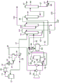
A prior art process for recovering gaseous products from a product mixture obtained by contacting a hydrocarbon feed with a catalyst in a fluid catalytic cracking process is shown in fig. 1. The gas mixture from the top of the main fractionation column 12 is supplied to an overhead cooler-condenser 16 via a gas conduit 14. The gas-liquid fraction thus obtained is separated in an overhead receiver tank separator 24. A separated liquid fraction referred to as unstabilized naphtha is supplied as lean oil to primary absorber 75 via liquid conduit 27. The gaseous fraction is supplied via conduit 26 to the suction of the first stage compressor 76. The vent stream is separated into gaseous and liquid fractions in interstage tank 80 after being cooled in interstage cooler 78 via conduit 77. The gas fraction from interstage tank 80 is supplied to second stage compressor 84 via conduit 81. The interstage liquid fraction from interstage tank 80 via conduit 82 is combined in conduit 85 with the gaseous fraction compressed in second stage 84. The combined stream in conduit 85 is further combined with the oil-rich stream liquid from the primary absorber 75 via conduit 94 and the overhead gas fraction from the stripper 92 via conduit 93. The resulting stream 87, after cooling in high pressure cooler 86, is separated into gaseous and liquid fractions in high pressure receiver separator 89.
The liquid fraction obtained from separator 89 is fed via conduit 91 to stripper 92 where components lighter than ethane are stripped from the feed and recycled via conduit 93 back to high pressure separator 89. The bottoms of stripper 92 is fed via conduit 95 to a debutanizer 96 where components lighter than butane present in the feed are separated as overheads and further fed via conduit 97 to a propylene separation unit. The bottoms of the debutanizer column 96 in conduit 97 is cooled in exchanger 98 to 38 c to 40 c before being split to gasoline recycle and supplied via conduit 100 to the primary absorber column 75.
Containing lights and C from high pressure separator 893—C5The gaseous fraction of the components is supplied via conduit 90 to the bottom of the primary absorber 75, where C3—C5The components are absorbed by the lean oil of the absorption tower flowing downwards. The gas fraction obtained from the primary absorption column 75 is supplied to a sponge absorber (sponge absorber)102 via a conduit 101. The resulting gas fraction in conduit 103 from sponge absorber 102 contains C via conduit 104 using light cycle oil as lean oil in sponge absorber 1022And lighter light gases and some C3And (4) loss. The absorbed hydrocarbons in the sponge absorber 102 are recycled back to the main fractionator via conduit 105.
As explained above, existing methods of recovering gaseous products from a product mixture obtained by contacting a hydrocarbon feed with a catalyst in a fluid catalytic cracking process use unstabilized gasoline from the overhead receiver of a main fractionator as the lean oil of a gas concentration primary absorber. However, heating the unstabilized gasoline and flashing the light ends and propylene prior to sending to the primary absorber increases the overall propylene recovery in the gas concentration unit. This design not only improves propylene recovery, but also makes the use of a flash tank more economical than other conventional processes used in gas concentration units, primarily recycling gasoline from the debutanizer, which increases equipment size and water costs (utilities). This design would increase the load on the wet gas compressor by 2% to 5%, but would be much more economical than increasing the gasoline recycle in the gas concentration unit. For new plant designs, it becomes somewhat uneconomical to increase propylene recovery using conventional methods.
The capital investment to increase propylene recovery is too large for existing plants and requires many plant modifications. With the present invention and for the design of a new plant, propylene recoveries approaching 99.6% are economically feasible. For the existing device, the propylene recovery rate can be improved by nearly 1% under the condition of not modifying the existing equipment. If the compressor is close to its maximum limit, the suction can be varied slightlyThe line pressure accommodates 2% to 5% of the additional load on the existing wet compressor. For existing FCC units, new equipment may be designed and installed during a typical turnaround or, in some cases, possibly while the unit is operating. In addition, for existing plants with equipment limitations of stripper, debutanizer, stripper reboiler, debutanizer reboiler, and debutanizer overhead condenser, gasoline recycle can be reduced and the same C maintained3And (4) recovering rate. This allows more feed to enter the gas concentration unit or more propylene to be produced in the FCC reactor.
As shown in the preferred embodiment in fig. 2, a process 100 for recovering propylene is depicted. In this embodiment, the gas mixture in conduit 14 from the top of the main fractionation column 12 is supplied to an overhead air cooler 16 and then to a cooler-condenser 20 via a gas/liquid conduit 18. The gas-liquid fraction thus obtained is separated in an overhead receiver 24. The separated liquid fraction unstabilized gasoline exits receiver 24 via liquid conduit 28 while the gas exits the receiver to the wet gas compressor via conduit 26. The unstabilized gasoline via conduit 28 is split and a portion of the liquid fraction is returned to the main fractionation column 12 in conduit 29. The net unstabilized gasoline liquid fraction in conduit 27 is then heated via feed/bottoms exchanger 30. The resulting stream in conduit 38 obtained from heat exchanger 30 is fed to heat exchanger 40 to be further heated by the stream in conduit 42. The stream in conduit 42 may be a process stream or LP steam. The liquid-gas mixture from heat exchanger 40 is fed via conduit 44 to flash tank 46.
The gas fraction in conduit 48 obtained from flash drum 46 is supplied to conduit 26 before the wet gas compressor. The flash tank vapor in conduit 48 contains approximately 70% of the light ends and propylene in the flash tank feed from conduit 44. The flash tank liquid in conduit 50 is pumped to the feed/bottoms exchanger 30, cooled to 35 ℃ to 40 ℃ in water cooler 34, and then sent to the primary absorber. Thus, the liquid sent to the primary absorber has less light materials and propylene, and therefore the load on the primary absorber is lower, which results in a higher propylene recovery of the gas concentration unit.
As shown in another preferred embodiment in fig. 3, a process 200 for recovering propylene is depicted. In this process a two-stage flash of unstabilized gasoline is used before being sent to the primary absorber of the gas concentration unit. In this embodiment, the gas mixture in conduit 14 from the top of the main fractionation column 12 is supplied to an overhead air cooler 16 and then to a cooler-condenser 20 via a gas/liquid conduit 18. The gas-liquid fraction thus obtained is separated in an overhead receiver 24. The separated liquid fraction unstabilized gasoline exits receiver 24 via liquid conduit 28 while the gas exits the receiver to the wet gas compressor via conduit 26. The unstabilized gasoline via conduit 28 is split and a portion of the liquid fraction is returned to the main fractionation column 12 in conduit 29. The net unstabilized gasoline liquid fraction in conduit 27 is then heated via feed/bottoms exchanger 30. The resulting stream in conduit 38 from heat exchanger 30 is fed to a split shell flash drum 60. The flash tank shown in fig. 2 comprises a split-shell flash tank having a first side 70 and a second side 72, wherein the first side 70 and the second side 72 are completely separated by a vertical wall and the contents of the first side and the second side do not contact each other. The gas fraction in conduit 48 obtained from flash tank 60 and side 70 is supplied to conduit 26 before the wet gas compressor.
The first bottoms stream 44 from the first side 70 of the split-shell flash drum 60 is pumped via conduit 44 to the heat exchanger 40 to be further heated by the stream in conduit 42. The stream in conduit 42 may be a process stream or LP steam. The resulting stream from exchanger 40 exits via conduit 51 and is directed to the second side 72 of the split-shell flash drum 60. A second overhead stream 58 from a second side 72 of the split shell flash drum 60 is provided to conduit 26 prior to the wet gas compressor. The second bottoms stream 50 from the second side 72 of the split shell flash drum 60 is pumped to the feed/bottoms exchanger 30, cooled to 35 ℃ to 40 ℃ in the water cooler 34, and then sent to the primary absorber. Thus, the liquid sent to the primary absorber has less light materials and propylene, and therefore the load on the primary absorber is lower, which results in a higher propylene recovery of the gas concentration unit.
Examples
The following examples are intended to further illustrate embodiments of the invention. The illustration of different embodiments is not intended to limit the claims to the specific details of these examples.
Example 1:
the FCC unit was designed according to the prior art process flow. A propylene recovery of 98.93 mole% can be achieved. Any additional propylene recovery using conventional processes is not possible and economical. By adding this new invention to the design of the unit, higher recovery rates can be achieved, which results in higher gains and return on investment periods of several months based on new equipment costs. A comparison of the case of adding a new device is shown in table 1.
TABLE 1

As shown in table 1 above, higher propylene recovery can be achieved with the new invention and the payback period for new equipment investment is expected to be several months. In addition, the above analysis was performed on the worst case of heating unstable gasoline using LP steam. The unstabilized gasoline can be heated in most cases with a waste heat process stream available from the gas recovery or FCC main fractionation section. This increases the annual revenue from MM $3.15 to MM $ 4.65.
Another analysis is the effect of the new invention on gasoline recycle.
For the same propylene as the base case of example 1 and by adding a flash tank, the gasoline recycle from the debutanizer to the absorber can be reduced by 50%. This provides a significant savings in equipment size and utilities (utilities) on the gas concentration equipment, such as the primary absorber, stripper, debutanizer, stripper reboiler, debutanizer reboiler/overhead condenser, and gas concentration unit water cooler.
Example 2:
for existing installations and if it is desired to reduce the load on the wet gas compressor due to capacity limitations, a split shell design may be used for the flash tank as shown in FIG. 2. The benefit is to reduce vapor entering the wet gas compressor while maintaining the same recovery in the gas concentration unit. The amount of propylene removed from the unstabilized gasoline was lower than the amount of vapor using the same single flash tank but entering the wet gas compressor as shown in table 2 below.
TABLE 2
257,508 kg/h of unstabilized gasoline stream

As shown in the above table, when split shell or divided wall cans are used, the flow into the wet gas compressor is reduced when nearly the same amount of propylene is removed from the unstabilized gasoline. Furthermore, the total flow into the wet gas compressor is at a slightly lower temperature.
It should be noted that various changes and modifications to the presently preferred embodiments described herein will be apparent to those skilled in the art. Such changes and modifications can be made without departing from the spirit and scope of the present subject matter and without diminishing its attendant advantages.
Detailed description of the preferred embodiments
While the following description is in conjunction with specific embodiments, it will be understood that this description is intended to illustrate and not limit the scope of the foregoing description and the appended claims.
A first embodiment of the invention is a process for recovering propylene comprising (i) contacting a hydrocarbon feed with a catalyst in a fluid catalytic cracking process to produce a product stream; (ii) distilling the product stream in a fractionation column to obtain a heavier liquid product and a gaseous overhead as a side-draw/bottoms fraction; (iii) cooling and condensing the gaseous overhead product and thereafter separating the resulting gas-liquid mixture in a receiver to obtain a liquid fraction and a light gas fraction; (iv) (iv) passing the gas fraction obtained from step (iii) on to a wet gas compressor train; (v) (iv) returning a first portion of the liquid fraction obtained in step (iii) to the fractionation column; (vi) (iv) feeding a second portion of the liquid fraction obtained in step (iii) to at least one heat exchanger to produce a heated stream; and (vii) feeding the heated stream to a flash tank to produce a flashed light ends stream and a bottoms liquid stream to be sent back to the wet gas compressor in step (iv), wherein the bottoms stream is sent to the one or more heat exchangers in step (vi) before the liquid stream is sent to the FCC gas concentration absorber. An embodiment of the invention is one, any or all of prior embodiments in this paragraph up through the first embodiment in this paragraph wherein the one or more heat exchangers heat the liquid fraction from 38 ℃ to 80 ℃. An embodiment of the invention is one, any or all of prior embodiments in this paragraph up through the first embodiment in this paragraph wherein the flashed light ends stream contains approximately 70% of the propylene in the flash tank feed. An embodiment of the invention is one, any or all of prior embodiments in this paragraph up through the first embodiment in this paragraph wherein the one or more heat exchangers use a waste heat process stream. An embodiment of the invention is one, any or all of prior embodiments in this paragraph up through the first embodiment in this paragraph wherein the liquid fraction is heated using two heat exchangers.
A second embodiment of the invention is a process for recovering propylene comprising (i) contacting a hydrocarbon feed with a catalyst in a fluid catalytic cracking process to produce a product stream; (ii) distilling the product stream in a fractionation column to obtain a heavier liquid product and a gaseous overhead as a side-draw/bottoms fraction; (iii) cooling and condensing the gaseous overhead product and thereafter separating the resulting gas-liquid mixture in a receiver to obtain a liquid fraction and a light gas fraction; (iv) (iv) passing the gas fraction obtained from step (iii) on to a wet gas compressor; (v) (iv) returning a first portion of the liquid fraction obtained in step (iii) to the fractionation column; (vi) (iv) feeding a second portion of the liquid fraction obtained in step (iii) to at least one heat exchanger to produce a heated stream; and (vii) feeding the heated stream to a split-shell flash tank having a first side and a second side, wherein the heated stream is directed to the first side of the split shell to produce a first flashed light ends stream and a first bottoms stream to be sent back to the wet gas compressor in step (iv), wherein the bottoms stream is heated and directed to the second side of the split-shell flash tank to produce a second flashed light ends stream and a second bottoms stream to be sent back to the wet gas compressor in step (iv), wherein the second bottoms stream is directed to the one or more heat exchangers in step (vi) before the liquid stream is directed to the FCC gas concentration absorber. An embodiment of the invention is one, any or all of prior embodiments in this paragraph up through the second embodiment in this paragraph wherein the one or more heat exchangers heat the liquid fraction from 38 ℃ to 80 ℃. An embodiment of the invention is one, any or all of prior embodiments in this paragraph up through the second embodiment in this paragraph wherein the flashed light ends stream contains approximately 70% of the propylene in the flash tank feed. An embodiment of the invention is one, any or all of prior embodiments in this paragraph up through the second embodiment in this paragraph wherein the one or more heat exchangers use a waste heat process stream. An embodiment of the invention is one, any or all of prior embodiments in this paragraph up through the second embodiment in this paragraph wherein the liquid fraction is heated using two heat exchangers.
Without further elaboration, it is believed that one skilled in the art can, using the preceding description, utilize the present invention to its fullest extent and readily ascertain the essential characteristics of the present invention, and that various changes and modifications can be made and adapted to various uses and conditions without departing from the spirit and scope thereof. Accordingly, the foregoing preferred specific embodiments are to be construed as merely illustrative, and not limitative of the remainder of the disclosure in any way whatsoever, and is intended to cover various modifications and equivalent arrangements included within the scope of the appended claims.
Unless otherwise indicated, all temperatures are set forth above in degrees Celsius and all parts and percentages are by weight.
Claims (5)
1. A process for recovering propylene comprising:
(i) contacting a hydrocarbon feed with a catalyst in a fluid catalytic cracking process to produce a product stream;
(ii) distilling the product stream in a fractionation column to obtain a heavier liquid product and a gaseous overhead as a side-draw/bottoms fraction;
(iii) cooling and condensing the gaseous overhead product and thereafter separating the resulting gas-liquid mixture in a receiver to obtain an unstabilized gasoline liquid fraction and a light gas fraction;
(iv) (iv) passing the gas fraction obtained from step (iii) on to a wet gas compressor train;
(v) (iv) returning a first portion of the liquid fraction obtained in step (iii) to the fractionation column;
(vi) (iv) feeding a second portion of the liquid fraction obtained in step (iii) to at least one heat exchanger to produce a heated stream; and
(vii) feeding the heated stream to a flash drum to produce a flashed light ends stream and a bottoms liquid stream, wherein the flashed light ends stream comprises light ends and propylene;
(viii) (iv) passing the flash light ends stream to a wet gas compressor train in step (iv); and
(ix) (vii) passing the bottoms liquid stream to the one or more heat exchangers in step (vi) and then passing the liquid stream to an FCC gas concentration absorber.
2. The process of claim 1, wherein the at least one heat exchanger heats the second portion of the liquid fraction obtained in step (iii) from 38 ℃ to 80 ℃.
3. The process of claim 1, wherein the flashed light ends stream contains approximately 70% of the propylene in the flash tank feed.
4. The method of claim 1, wherein the one or more heat exchangers use a waste heat process stream.
5. The process of claim 1, wherein the second portion of the liquid fraction obtained in step (iii) is heated using two heat exchangers.
Applications Claiming Priority (3)
| Application Number | Priority Date | Filing Date | Title |
|---|---|---|---|
| US201562268041P | 2015-12-16 | 2015-12-16 | |
| US62/268,041 | 2015-12-17 | ||
| PCT/US2016/063923 WO2017105818A1 (en) | 2015-12-16 | 2016-11-29 | Process for improving propylene recovery from fcc recovery unit |
Publications (2)
| Publication Number | Publication Date |
|---|---|
| CN108473391A CN108473391A (en) | 2018-08-31 |
| CN108473391B true CN108473391B (en) | 2021-08-17 |
Family
ID=59057374
Family Applications (1)
| Application Number | Title | Priority Date | Filing Date |
|---|---|---|---|
| CN201680073279.3A Active CN108473391B (en) | 2015-12-16 | 2016-11-29 | Process for improving propylene recovery of FCC recovery units |
Country Status (4)
| Country | Link |
|---|---|
| US (1) | US10487271B2 (en) |
| EP (1) | EP3390329B1 (en) |
| CN (1) | CN108473391B (en) |
| WO (1) | WO2017105818A1 (en) |
Families Citing this family (4)
| Publication number | Priority date | Publication date | Assignee | Title |
|---|---|---|---|---|
| US10471368B1 (en) * | 2018-06-29 | 2019-11-12 | Uop Llc | Process for separation of propylene from a liquefied petroleum gas stream |
| CN113350822B (en) * | 2021-06-09 | 2022-06-21 | 中山大学 | A fractionation device |
| CN115721951A (en) * | 2022-10-28 | 2023-03-03 | 新疆心连心能源化工有限公司 | Gasification tail gas treatment device and using method thereof |
| US12378172B2 (en) | 2022-11-16 | 2025-08-05 | Uop Llc | Process for recovering cracked product |
Citations (8)
| Publication number | Priority date | Publication date | Assignee | Title |
|---|---|---|---|---|
| US3893905A (en) * | 1973-09-21 | 1975-07-08 | Universal Oil Prod Co | Fluid catalytic cracking process with improved propylene recovery |
| EP0509592A1 (en) * | 1991-04-18 | 1992-10-21 | AGIP PETROLI S.p.A. | Improved process for recovering high-value hydrocarbon fractions from light refinery products |
| US5360533A (en) * | 1993-06-08 | 1994-11-01 | Uop | Direct dry gas recovery from FCC reactor |
| CN101417915A (en) * | 2007-10-26 | 2009-04-29 | 环球油品公司 | Integrated production of fcc-produced c3 and cumene |
| CN102040445A (en) * | 2009-10-14 | 2011-05-04 | 青岛石大卓越投资有限公司 | Technology device and method for preparing propylene by dehydrogenating propane or propane-enriched low carbon hydrocarbon |
| CN102597179A (en) * | 2009-11-09 | 2012-07-18 | 环球油品公司 | Apparatus and process for recovering fcc product |
| CN103946191A (en) * | 2011-11-18 | 2014-07-23 | 环球油品公司 | Methods and systems for olefin production |
| CN104650962A (en) * | 2013-11-19 | 2015-05-27 | 中国石油天然气股份有限公司 | An improved catalytic cracking process |
Family Cites Families (5)
| Publication number | Priority date | Publication date | Assignee | Title |
|---|---|---|---|---|
| US3122496A (en) * | 1960-08-26 | 1964-02-25 | Phillips Petroleum Co | Stripper-absorber method and apparatus |
| US6271433B1 (en) * | 1999-02-22 | 2001-08-07 | Stone & Webster Engineering Corp. | Cat cracker gas plant process for increased olefins recovery |
| US7074323B2 (en) * | 2000-03-03 | 2006-07-11 | Shell Oil Company | Use of low pressure distillate as absorber oil in a FCC recovery section |
| US8618344B2 (en) * | 2009-07-02 | 2013-12-31 | Reliance Industries Limited | Process for recovery of propylene and LPG from FCC fuel gas using stripped main column overhead distillate as absorber oil |
| US8414763B2 (en) * | 2009-11-09 | 2013-04-09 | Uop Llc | Process for recovering FCC product |
-
2016
- 2016-11-29 CN CN201680073279.3A patent/CN108473391B/en active Active
- 2016-11-29 EP EP16876356.3A patent/EP3390329B1/en active Active
- 2016-11-29 WO PCT/US2016/063923 patent/WO2017105818A1/en not_active Ceased
-
2018
- 2018-05-31 US US15/994,906 patent/US10487271B2/en active Active
Patent Citations (8)
| Publication number | Priority date | Publication date | Assignee | Title |
|---|---|---|---|---|
| US3893905A (en) * | 1973-09-21 | 1975-07-08 | Universal Oil Prod Co | Fluid catalytic cracking process with improved propylene recovery |
| EP0509592A1 (en) * | 1991-04-18 | 1992-10-21 | AGIP PETROLI S.p.A. | Improved process for recovering high-value hydrocarbon fractions from light refinery products |
| US5360533A (en) * | 1993-06-08 | 1994-11-01 | Uop | Direct dry gas recovery from FCC reactor |
| CN101417915A (en) * | 2007-10-26 | 2009-04-29 | 环球油品公司 | Integrated production of fcc-produced c3 and cumene |
| CN102040445A (en) * | 2009-10-14 | 2011-05-04 | 青岛石大卓越投资有限公司 | Technology device and method for preparing propylene by dehydrogenating propane or propane-enriched low carbon hydrocarbon |
| CN102597179A (en) * | 2009-11-09 | 2012-07-18 | 环球油品公司 | Apparatus and process for recovering fcc product |
| CN103946191A (en) * | 2011-11-18 | 2014-07-23 | 环球油品公司 | Methods and systems for olefin production |
| CN104650962A (en) * | 2013-11-19 | 2015-05-27 | 中国石油天然气股份有限公司 | An improved catalytic cracking process |
Also Published As
| Publication number | Publication date |
|---|---|
| EP3390329A4 (en) | 2019-08-21 |
| US10487271B2 (en) | 2019-11-26 |
| CN108473391A (en) | 2018-08-31 |
| US20180273853A1 (en) | 2018-09-27 |
| EP3390329A1 (en) | 2018-10-24 |
| WO2017105818A1 (en) | 2017-06-22 |
| EP3390329B1 (en) | 2023-09-20 |
Similar Documents
| Publication | Publication Date | Title |
|---|---|---|
| US20110041550A1 (en) | Process and apparatus for the separation of light-boiling components from hydrocarbon mixtures | |
| CN107922854B (en) | Methods for LPG Recovery | |
| CN108473391B (en) | Process for improving propylene recovery of FCC recovery units | |
| WO2009064543A2 (en) | Splitter with multi-stage heat pump compressor and inter-reboiler | |
| WO1999030093B1 (en) | Enhanced ngl recovery processes | |
| US20200032677A1 (en) | Natural gas liquid fractionation plant waste heat conversion to potable water using modified multi-effect distillation system | |
| WO2013133987A1 (en) | Distillation column heat pump with compressor inlet superheater | |
| CN111225726B (en) | Method and apparatus for desorbent recovery | |
| CN108601988A (en) | Utilize dividing wall column distillation purifying mercaptan or thiophene | |
| RU2697800C2 (en) | Methods and apparatus for extracting ethylene from hydrocarbons | |
| US9637426B2 (en) | Methods and apparatuses for reforming of hydrocarbons including recovery of products using a recontacting zone | |
| CN106661459A (en) | Naphtha isomerization process comprising two thermally integrated steps | |
| CN111344267B (en) | Process and apparatus for isomerizing hydrocarbons | |
| JP7043126B6 (en) | A device for separating and recovering multiple types of hydrocarbons from LNG | |
| CN106350097A (en) | Process for the treatment of a hydrocarbon feed comprising hydrogen and c1 to c4 hydrocarbons | |
| CN105102405A (en) | Methods and apparatuses for isomerization of paraffins | |
| US12516004B2 (en) | Processes and apparatuses for separating aromatic and non-aromatic hydrocarbons | |
| CN115105851B (en) | Separation process and separation device for sulfuric acid alkylation reaction product | |
| CN115066478B (en) | Site and cost-effective apparatus and method for separating one or more purified hydrocarbon streams from a crude hydrocarbon stream, such as for naphtha stabilization and LPG recovery | |
| JP7586647B2 (en) | Method and apparatus for concentrating alkenes and/or alkanes | |
| US9816753B2 (en) | Methods and apparatuses for reforming of hydrocarbons including recovery of products using an absorption zone | |
| US7132044B2 (en) | Device that comprises recycling to a separator a liquid effluent that is obtained from an absorber and is mixed with a feedstock | |
| US9399743B2 (en) | Process for converting a hydrocarbon feed and apparatus relating thereto |
Legal Events
| Date | Code | Title | Description |
|---|---|---|---|
| PB01 | Publication | ||
| PB01 | Publication | ||
| SE01 | Entry into force of request for substantive examination | ||
| SE01 | Entry into force of request for substantive examination | ||
| GR01 | Patent grant | ||
| GR01 | Patent grant |