CN108390464B - Flexible traveling wave excitation method of non-contact electric energy transmission device - Google Patents
Flexible traveling wave excitation method of non-contact electric energy transmission device Download PDFInfo
- Publication number
- CN108390464B CN108390464B CN201810209877.XA CN201810209877A CN108390464B CN 108390464 B CN108390464 B CN 108390464B CN 201810209877 A CN201810209877 A CN 201810209877A CN 108390464 B CN108390464 B CN 108390464B
- Authority
- CN
- China
- Prior art keywords
- excitation
- winding
- primary
- magnetic field
- current
- Prior art date
- Legal status (The legal status is an assumption and is not a legal conclusion. Google has not performed a legal analysis and makes no representation as to the accuracy of the status listed.)
- Active
Links
Images


Classifications
-
- H—ELECTRICITY
- H02—GENERATION; CONVERSION OR DISTRIBUTION OF ELECTRIC POWER
- H02J—ELECTRIC POWER NETWORKS; CIRCUIT ARRANGEMENTS OR SYSTEMS FOR SUPPLYING OR DISTRIBUTING ELECTRIC POWER; SYSTEMS FOR STORING ELECTRIC ENERGY
- H02J50/00—Circuit arrangements or systems for wireless supply or distribution of electric power
- H02J50/10—Circuit arrangements or systems for wireless supply or distribution of electric power using inductive coupling
-
- H—ELECTRICITY
- H02—GENERATION; CONVERSION OR DISTRIBUTION OF ELECTRIC POWER
- H02J—ELECTRIC POWER NETWORKS; CIRCUIT ARRANGEMENTS OR SYSTEMS FOR SUPPLYING OR DISTRIBUTING ELECTRIC POWER; SYSTEMS FOR STORING ELECTRIC ENERGY
- H02J50/00—Circuit arrangements or systems for wireless supply or distribution of electric power
- H02J50/90—Circuit arrangements or systems for wireless supply or distribution of electric power involving detection or optimisation of position, e.g. alignment
Landscapes
- Engineering & Computer Science (AREA)
- Computer Networks & Wireless Communication (AREA)
- Power Engineering (AREA)
- Coils Of Transformers For General Uses (AREA)
- Inverter Devices (AREA)
Abstract
本发明公开了一种非接触电能传输装置与柔性行波激励方法,该非接触电能传输装置包括原边功率变换单元、原边绕组、原边磁芯、原边控制器、副边绕组、副边磁芯、副边功率变换单元及负载。所述控制方法为:通过对原边绕组施加自由、灵活的激励来构造波峰(长轴)波谷(磁场短轴)位置可调的空间磁场,从而适应不同绕阻结构、位置的副边绕组。本发明装置及控制方法,通过将磁场长/短轴定向至盘式/DD绕组的中心,实现了对空间磁场的柔性调控,解决了非接触电能传输系统输出特性对位置的敏感度高、特殊位置无功率输出能力(感应盲点)以及不同绕组结构的副边绕组的互操作性、兼容性问题,提高了非接触电能传输系统的实用性与适用性。

The invention discloses a non-contact power transmission device and a flexible traveling wave excitation method. The non-contact power transmission device comprises a primary side power conversion unit, a primary side winding, a primary side magnetic core, a primary side controller, a secondary side winding, a secondary side winding and a secondary side winding. Side magnetic core, secondary side power conversion unit and load. The control method is: by applying free and flexible excitation to the primary winding to construct a space magnetic field with adjustable peak (long axis) and trough (magnetic field short axis) positions, so as to adapt to secondary windings with different winding structures and positions. The device and control method of the present invention realizes the flexible regulation of the space magnetic field by orienting the long/short axis of the magnetic field to the center of the disc/DD winding, and solves the problem that the output characteristics of the non-contact power transmission system have high sensitivity to position and special characteristics. The positional non-power output capability (induction blind spot) and the interoperability and compatibility of secondary windings with different winding structures improve the practicability and applicability of the non-contact power transmission system.
Description
技术领域technical field
本发明涉及电力电子技术、非接触供电技术,具体涉及一种“柔性行波磁场定向调控”非接触电能传输装置及其控制方法。The invention relates to power electronics technology and non-contact power supply technology, in particular to a "flexible traveling wave magnetic field directional regulation" non-contact power transmission device and a control method thereof.
背景技术Background technique
非接触供电利用磁场耦合实现“无线供电”,即采用原副边完全分离的非接触变压器,通过高频磁场的耦合传输电能,使得在能量传递过程中原边 (供电侧)和副边(用电侧)无物理连接。与传统的接触式供电相比,非接触供电使用方便、安全,无火花及触电危险,无积尘和接触损耗,无机械磨损和相应的维护问题,可适应多种恶劣天气和环境,便于实现自动供电,具有良好的应用前景。Non-contact power supply uses magnetic field coupling to realize "wireless power supply", that is, a non-contact transformer with completely separated primary and secondary sides is used to transmit electric energy through the coupling of high-frequency magnetic fields, so that in the process of energy transfer, the primary side (power supply side) and the secondary side (power consumption) side) no physical connection. Compared with traditional contact power supply, non-contact power supply is convenient and safe to use, without the danger of sparks and electric shocks, without dust accumulation and contact loss, without mechanical wear and corresponding maintenance problems, and can adapt to a variety of harsh weather and environments, and is easy to implement Automatic power supply, with good application prospects.
虽然非接触供电优点突出,但是依然存在一些实际问题需要解决,其中一个关键问题就是大范围位置变化下的稳定功率传输问题。当副边绕组对位不准或存在错位时,输出功率会出现明显下降,甚至会出现下降至0即感应盲点问题。对此,其中常用的两类绕组结构(DD(图2)以及盘式(图3)) 存在不同的解决方案。Although the advantages of non-contact power supply are outstanding, there are still some practical problems that need to be solved. One of the key problems is the stable power transmission under a large range of position changes. When the secondary winding is inaccurate or misaligned, the output power will drop significantly, or even drop to 0, that is, the problem of induction blind spots. For this, there are different solutions for the commonly used two types of winding structures (DD (Fig. 2) and disc (Fig. 3)).
为了解决盘式绕组的功率传输能力的位置敏感度高的问题,香港城市大学,S.Y.R.Hui and W.W.C.Ho,‘A New Generation ofUniversal Contactless BatteryCharging Platform for Portable Consumer Electronic Equipment’,IEEETransactions on Power Electronics,vol.20,no.3,pp.620–627,May 2005.提出了蜂窝状六边形PCB原边绕组阵列,通过增加原边绕组的数量,多层绕组优化、分布布局,以一种“多对一”的方式在负载线圈平面构造一个更为均匀的磁场,从而保证副边在不同位置下的功率传输能力。但是,因为该方案使用了大量紧密层叠的原边绕组阵列,铜重增加,且不同绕组串联同时供电,铜损大,效率低。福州大学X.Huang,W.Chen,and Q.Chen,‘A designalgorithm of circular transmitting coil to achieve uniform magnetic fielddistribution in WPT applications’,in Future Energy Electronics Conference(IFEEC),2015 IEEE 2nd International,2015,pp.1–5.采用基于充电平台内有限点的磁感应强度的数值计算以及以均匀磁场为目标的自适应基因算法,设计不同半径处的匝数分配,以一种“大对小”的方式减小负载线圈在不同位置的输出差异。但是该方案依然存在原边铜损大,效率低的问题,在为单个负载供电时该缺点尤为明显。In order to solve the problem of high position sensitivity of the power transfer capability of the disc winding, City University of Hong Kong, S.Y.R.Hui and W.W.C.Ho, 'A New Generation of Universal Contactless BatteryCharging Platform for Portable Consumer Electronic Equipment', IEEE Transactions on Power Electronics, vol.20 , no.3, pp.620–627, May 2005. A honeycomb hexagonal PCB primary winding array is proposed. By increasing the number of primary windings, multi-layer windings are optimized and distributed layout, in a "many-to-one" ” method to construct a more uniform magnetic field in the plane of the load coil, thereby ensuring the power transmission capability of the secondary side at different positions. However, because this scheme uses a large number of closely stacked primary winding arrays, the copper weight increases, and different windings are connected in series to supply power at the same time, resulting in large copper losses and low efficiency. Fuzhou University X.Huang,W.Chen,and Q.Chen,'A designalgorithm of circular transmitting coil to achieve uniform magnetic fielddistribution in WPT applications',in Future Energy Electronics Conference(IFEEC),2015 IEEE 2nd International,2015,pp. 1–5. Using the numerical calculation based on the magnetic induction intensity of finite points in the charging platform and the adaptive genetic algorithm aiming at a uniform magnetic field, the number of turns at different radii is designed to be allocated in a “large to small” manner. The output difference of the load coil at different positions. However, this solution still has the problems of large copper loss on the primary side and low efficiency, especially when supplying power to a single load.
针对非接触无线电能传输系统中另一类线圈结构,DD型绕组(磁场如图4所示)在1/3的横向错位时出现磁场抵消-输出功率降为0(如图5所示) 问题,很多文献在副边DD绕组的基础上增加Q绕组来解决“感应盲点问题”。但是该解决方案只是解决了“感应盲点”问题,只能适应较小的错位情况,当错位更大时,输出功率下降的问题依然存在。For another type of coil structure in the non-contact wireless power transmission system, the DD-type winding (the magnetic field is shown in Figure 4) has the problem of magnetic field cancellation when the lateral dislocation is 1/3 - the output power is reduced to 0 (as shown in Figure 5) , many literatures add Q winding to the secondary side DD winding to solve the "induction blind spot problem". However, this solution only solves the "induction blind spot" problem and can only adapt to small dislocations. When the dislocation is larger, the problem of output power drop still exists.
从上述讨论不难发现,针对盘式以及DD这两类绕组的错位容忍度的解决方法都各有不足。此外,由于这两类绕组结构在磁场设计(如图4、图6) 优化方面存在矛盾,因此上述两类解决办法都只能适用于特定的一类绕组,无法兼容。所以,实际应用中依靠一套原边系统来解决不同绕组结构的副边在大范围错位下稳定功率传输问题,即“互操作”性问题,仍然没有解决。From the above discussion, it is not difficult to find that the solutions for the dislocation tolerance of the disc and DD windings have their own shortcomings. In addition, because the two types of winding structures are contradictory in the optimization of the magnetic field design (as shown in Figure 4 and Figure 6), the above two types of solutions can only be applied to a specific type of winding and are not compatible. Therefore, in practical applications, a set of primary side system is used to solve the problem of stable power transmission of the secondary side of different winding structures under a wide range of dislocation, that is, the "interoperability" problem, which is still unsolved.
可见,位置变化带来的“感应盲点”、大范围错位下传输功率下降、“互操作”性、系统效率下降以及可靠性问题,都制约了非接触供电的发展及市场推广,亟待解决。对此,本发明提出了“柔性行波磁场定向调控”激励方法。所谓“柔性行波磁场定向调控”,即通过对非接触供电系统的原边绕组施加自由、灵活、可变的激励来实现对空间磁场动态调节,从而适应副边位置、绕组结构等关键参数的变化,实现自适应的优化控制。其优点在于,通过“柔性行波磁场”可以进行自适应磁场匹配与优化,解决无线系统互操作性难、错位容忍度低的难题。It can be seen that the "induction blind spot" caused by the position change, the reduction of transmission power under large-scale dislocation, the "interoperability", the decline of system efficiency and the reliability problems all restrict the development and market promotion of contactless power supply, and need to be solved urgently. In this regard, the present invention proposes a "flexible traveling wave magnetic field directional regulation" excitation method. The so-called "flexible traveling wave magnetic field directional regulation" means that the space magnetic field can be dynamically adjusted by applying free, flexible and variable excitation to the primary winding of the non-contact power supply system, so as to adapt to the key parameters such as the position of the secondary side and the winding structure. changes to achieve adaptive optimal control. The advantage is that adaptive magnetic field matching and optimization can be carried out through the "flexible traveling wave magnetic field", which solves the problems of difficult interoperability and low tolerance of misalignment in wireless systems.
发明内容SUMMARY OF THE INVENTION
为了解决上述技术问题,本发明提供一种磁场定向控制的非接触电能传输装置及其控制方法。In order to solve the above technical problems, the present invention provides a non-contact power transmission device with magnetic field orientation control and a control method thereof.
本发明的具体技术方案如下:The concrete technical scheme of the present invention is as follows:
该柔性行波磁场定向调控的非接触电能传输装置,包括原边功率变换单元、原边绕组、原边磁芯、原边控制器、副边绕组、副边磁芯、副边功率变换单元以及负载;The non-contact power transmission device for directional regulation of the flexible traveling wave magnetic field comprises a primary side power conversion unit, a primary side winding, a primary side magnetic core, a primary side controller, a secondary side winding, a secondary side magnetic core, a secondary side power conversion unit and load;
其中,原边绕组可包括一个或多个绕组单元,每个绕组单元至少包含两个空间位置不同的独立线圈,且至少有两个线圈的激励电流大小以及相位可由原边控制器通过原边功率变换单元独立调节,来构造形成磁场幅度和波峰波谷位置连续受控可调的柔性行波磁场;原边功率变换单元包含逆变器和补偿网络为线圈提供激励;原边控制器通过功率变化单元来对原边绕组施加可变的行波激励,使强磁场分布区域自动追踪副边位置,实现磁场定向控制。Among them, the primary winding can include one or more winding units, each winding unit includes at least two independent coils with different spatial positions, and the excitation current size and phase of at least two coils can be controlled by the primary controller through the primary power The transformation unit is independently adjusted to construct a flexible traveling wave magnetic field with continuously controlled and adjustable magnetic field amplitude and peak and trough positions; the primary side power transformation unit includes an inverter and a compensation network to provide excitation for the coil; the primary side controller uses the power transformation unit to provide excitation. To apply variable traveling wave excitation to the primary winding, the strong magnetic field distribution area can automatically track the position of the secondary side and realize the magnetic field oriented control.
其中,所述原边绕组可由多个绕组单元通过平移、旋转及其组合方式,构成得到。Wherein, the primary winding can be formed by a plurality of winding units through translation, rotation and combinations thereof.
其中,所述装置还包括原副边电压和/或电流和/或功率检测或估算电路;原副边可通过蓝牙、WIFI、ZigBee、磁反馈、红外、射频等无线方式进行通信。Wherein, the device further includes a primary and secondary side voltage and/or current and/or power detection or estimation circuit; the primary and secondary sides can communicate via Bluetooth, WIFI, ZigBee, magnetic feedback, infrared, radio frequency and other wireless methods.
一种柔性行波激励方法,其特征在于,在副边位置已知的条件下可以由磁场定向调控直接确定原边绕组各线圈电流的激励关系,副边位置未知的条件下通过激励搜索的方式确定最优激励方法,实现副边变结构、变位置下的互操作性与兼容性。如附图7的流程图所示,其具体步骤如下:A flexible traveling wave excitation method, which is characterized in that the excitation relationship of each coil current of the primary winding can be directly determined by the magnetic field orientation regulation under the condition that the position of the secondary side is known, and the excitation search method is used under the condition that the position of the secondary side is unknown. Determine the optimal excitation method to realize the interoperability and compatibility under the variable structure and position of the secondary side. As shown in the flowchart of accompanying
S100:判断是否具备副边位置信息,若有,则执行S102,否则执行S103;S100: determine whether there is secondary side position information, if so, execute S102, otherwise execute S103;
S102:实施磁场定向调控;S102: implement magnetic field orientation regulation;
A.给出副边绕组的中心轴线的位置坐标xs。其中,副边绕组的位置坐标xs可由摄像头、GPS、行波测距、毫米波测距、RFID测距、超声波测距等方法得到;A. Give the position coordinate xs of the center axis of the secondary winding. Among them, the position coordinates x s of the secondary winding can be obtained by methods such as camera, GPS, traveling wave ranging, millimeter wave ranging, RFID ranging, ultrasonic ranging, etc.;
B.根据给定的位置坐标,确定原边绕组空间磁场的关键特征参数,包括(长轴位置xm、短轴位置xn):若副边为DD绕组,则短轴位置xn取xs;若副边为盘式绕组,则长轴位置xm取xs,磁场幅度L取1~10 之间任一值。传统的行波激励方式,原边激励参数固定,尤其是相位关系,不随副边位置调整。而本发明所提磁场定向调控方式,根据副边位置的不同对原边激励参数实施动态调整,将最强磁场分布区域自动追踪副边位置,实现了对空间磁场的最大利用,在相同的磁场幅度L下,兼顾了系统的功率输出能力与系统效率,为本控制方法不同于其他控制方法的核心所在。B. According to the given position coordinates, determine the key characteristic parameters of the space magnetic field of the primary winding, including (long axis position x m , short axis position x n ): if the secondary side is a DD winding, the short axis position x n takes x s ; if the secondary side is a disc winding, the long axis position x m takes x s , and the magnetic field amplitude L takes any value between 1 and 10 . In the traditional traveling wave excitation method, the excitation parameters of the primary side are fixed, especially the phase relationship, which is not adjusted with the position of the secondary side. The magnetic field directional control method proposed in the present invention dynamically adjusts the excitation parameters of the primary side according to the different positions of the secondary side, and automatically tracks the position of the secondary side in the distribution area of the strongest magnetic field, thereby realizing the maximum utilization of the space magnetic field. Under the amplitude L, the power output capability and system efficiency of the system are taken into account, and the core of this control method is different from other control methods.
C.根据长轴位置(xm)或短轴位置(xn)参数确定原边绕组各线圈电流所施加电流的幅值及相位关系:I1=I1*;I2=I2*;
为了便于理解,此处对磁场长轴、短轴的含义作出说明。如附图8所示,以原边绕组有两个线圈构成为例,当副边方形线圈的中心位置(xs)变化时,此处以沿x轴移动为例,不同位置xs下的副边输出电压不同。而对于传统行波磁场,不同位置xs下的输出电压相同,但输出电压较小,增益低,且功率传输效率不高。在本发明中,对于任一固定的原边线圈激励关系(幅值大小、相位关系),副边中心移动至输出电压最大的位置,即为磁场长轴位置xm(磁场波峰);副边输出电压最小值所在位置,即为磁场短轴位置xn(磁场波谷)。最大输出电压Vo表征该种激励条件下的磁场幅度L。在不同的原边激励下,长轴位置xm、短轴位置xn也各不同。本专利所提方案中,原边绕组优先采用分布式绕制,保证波峰、波谷位置在不同激励条件下实现连续受控可调。长轴位置(xm)、短轴位置(xn)与原边绕组各线圈电流的激励关系,随原边绕组的分布的变化而变化,分布绕组。可根据麦克斯韦方程组、毕奥萨伐尔定律实时计算得到,或者离线计算生成离线表,也可由Ansys、Comsol等电磁场仿真软件通过仿真得到离线查找表。For ease of understanding, the meanings of the long axis and the short axis of the magnetic field are explained here. As shown in FIG. 8 , taking the primary side winding with two coils as an example, when the center position (x s ) of the secondary side square coil changes, taking the movement along the x-axis as an example, the secondary side at different positions x s side output voltage is different. For the traditional traveling wave magnetic field, the output voltage at different positions x s is the same, but the output voltage is small, the gain is low, and the power transfer efficiency is not high. In the present invention, for any fixed excitation relationship (amplitude, phase relationship) of the primary coil, the center of the secondary side moves to the position where the output voltage is the largest, which is the position of the long axis of the magnetic field x m (the peak of the magnetic field); The position of the minimum output voltage is the position of the short axis of the magnetic field x n (magnetic field trough). The maximum output voltage V o characterizes the magnetic field amplitude L under this excitation condition. Under different primary excitations, the long axis position x m and the short axis position x n are also different. In the solution proposed in this patent, the primary winding is preferably distributed winding to ensure that the positions of the peaks and valleys are continuously controlled and adjustable under different excitation conditions. The excitation relationship between the position of the long axis (x m ), the position of the short axis (x n ) and the current of each coil of the primary winding changes with the distribution of the primary winding, and the winding is distributed. It can be calculated in real time according to Maxwell's equations and Bio-Savart's law, or offline table can be generated by offline calculation, and offline lookup table can also be obtained through simulation by electromagnetic field simulation software such as Ansys and Comsol.
原边绕组由两线圈构成时的一种离线表构成如下:An off-line table when the primary winding is composed of two coils is composed as follows:

S103:以原边绕组中的任一点设为原边位置参考点;S103: Set any point in the primary winding as the primary position reference point;
S104:固定副边负载;其中负载可为副边实际工作长挂的死负载,也可为由开关通断仅在预激励过程程中接入的固定死负载,也可为实际工作时所接负载;S104: Fixed secondary side load; the load can be a dead load that hangs on the actual work of the secondary side, or a fixed dead load connected only by the switch on and off during the pre-excitation process, or it can be connected during actual work. load;
S105:选择激励搜索方法,若选择遍历搜索寻优,则执行S106,若选择特定激励变化轨迹搜索寻优,则执行S107;若选择最优寻优方法,则执行 S108。S105: Select an excitation search method. If traversal search is selected for optimization, execute S106. If a specific excitation change trajectory is selected for search and optimization, execute S107; if an optimal optimization method is selected, execute S108.
S106:遍历搜索寻优,具体的实施流程图如附图9所示,步骤如下:S106: traversing the search for optimization, the specific implementation flowchart is shown in FIG. 9, and the steps are as follows:
A.固定原边各线圈的激励电流幅值为一固定值,以某一线圈激励电流为相位(如)参考,对相位

B.控制器记录、存储每组激励下的各线圈激励电流的大小、相位关系以及该组激励下的响应(响应包括输出功率和/或效率和/或输出电压和/或输出电流);B. The controller records and stores the magnitude and phase relationship of the excitation current of each coil under each group of excitation, and the response under the group of excitation (the response includes output power and/or efficiency and/or output voltage and/or output current);
C.遍历完成后,以最大输出功率或最大效率为目标存储对应的激励条件:I1=I1*;I2=I2*;
其中,步骤S106中,变化原边绕组各线圈激励,还可以采用固定各线圈输入交流电压幅值如10~50V,对两者之间的相位差进行一次遍历;还可以采用固定各线圈电流相位
S107:特定激励变化轨迹搜索寻优,具体的实施流程图如附图10所示,步骤如下:S107: Search and optimize a specific excitation change trajectory. The specific implementation flowchart is shown in FIG. 10, and the steps are as follows:
A.改变激励条件,由控制器实时计算或查离线表得到xm、xn、L,对xm和或/xn依次进行遍历;A. Change the excitation conditions, obtain x m , x n , L by real-time calculation by the controller or look up the off-line table, and traverse x m and/x n in turn;
B.检测并存储原边输入功率或副边输出功率,统称为Q,形成(xm,xn, Q/L2)数据;B. Detect and store the input power of the primary side or the output power of the secondary side, collectively referred to as Q, to form (x m , x n , Q/L 2 ) data;
C.以最大Q/L2为目标搜索找到其相应的激励关系:I1=I1*;I2=I2*;
S108:A.以冒泡、二分法等最优搜索改变激励条件;B.存储、比较各组激励下原边各线圈的激励电流的大小、相位关系以及该组激励下的响应(响应包括输出功率和/或效率和/或输出电压和/或输出电流);C.比较得到满足优化条件(最大输出功率、最大效率)所对应的激励条件:I1=I1*;I2=I2*;
S109:保证原边绕组内各线圈所施加电流的幅值比例及相位关系不变,采用基于输出误差反馈的闭环调节方法,改变激励电流的幅值大小、频率、相位等使得副边输出电压、输出电流或输出功率满足要求。S109: Ensure that the amplitude ratio and phase relationship of the current applied to each coil in the primary winding remain unchanged, and adopt a closed-loop adjustment method based on output error feedback to change the amplitude, frequency, and phase of the excitation current so that the secondary output voltage, The output current or output power meets the requirements.
其中,步骤S102C、S107中的长轴位置(xm)、短轴位置(xn)与原边绕组各线圈电流的激励关系,可根据麦克斯韦方程组、毕奥萨伐尔定律实时计算得到,或者离线计算生成离线表,也可由Ansys、Comsol等电磁场仿真软件通过仿真得到离线表。离线表内包含每个长轴位置、短轴位置下的激励电流关系。Wherein, the excitation relationship between the long-axis position (x m ), the short-axis position (x n ) and the current of each coil of the primary winding in steps S102C and S107 can be calculated in real time according to Maxwell's equations and Bio-Savart's law, Alternatively, the offline table can be generated by offline calculation, or the offline table can be obtained through simulation by electromagnetic field simulation software such as Ansys and Comsol. The offline table contains the excitation current relationship at each long-axis position and short-axis position.
更特殊的,若原边预激励绕组单元由沿直线布置、重叠50%的两个独立线圈组成的原边预激励绕组单元构成,长轴位置xm、短轴位置xn以及磁场幅度L与所需施加激励关系如下式所示:More specifically, if the primary pre-excitation winding unit is composed of two independent coils that are arranged in a straight line and overlapped by 50%, the long-axis position x m , the short-axis position x n and the magnetic field amplitude L are related to all of them. The incentive relationship to be applied is as follows:


其中I1、I2为两个线圈的电流大小,为I2相对于I1相位差,a为线圈宽度。将施加激励的电流大小、相位带入上式可以计算得到xm、xn以及L。将所需的xm、xn、L的带入上述方程同样可以求解得到所需施加的电流激励大小及相位差。在满足长短轴位置(xm、xn)以及磁场幅度的L的前提下,原边绕组各线圈电流的相位差
所述原边磁芯和副边磁芯均可选用硅钢片、铁氧体、非晶、微晶、超微晶、坡莫合金、或粉芯等导磁材料制成;或者空气、陶瓷、环氧或塑料等非导磁材料制成;或者由一种或多种导磁材料和/或一种或多种非导磁材料组合来实现。The primary side magnetic core and the secondary side magnetic core can be made of magnetic conductive materials such as silicon steel sheet, ferrite, amorphous, microcrystalline, ultra-microcrystalline, permalloy, or powder core; or air, ceramic, It is made of non-magnetic conductive materials such as epoxy or plastic; or it is realized by one or more magnetic conductive materials and/or a combination of one or more non-magnetic conductive materials.
所述原边绕组、副边绕组的导线均可选用实心导线、Litz线、铜皮、铜管,或PCB绕组。The wires of the primary winding and the secondary winding can be selected from solid wires, Litz wires, copper sheets, copper tubes, or PCB windings.
所述原边和/或副边外侧设有磁屏蔽层,该磁屏蔽层采用屏蔽板、箔、膜、或由屏蔽材料编织而成的屏蔽网或屏蔽布制成;A magnetic shielding layer is provided on the outer side of the primary side and/or the secondary side, and the magnetic shielding layer is made of shielding plate, foil, film, or shielding net or shielding cloth woven from shielding material;
所述磁屏蔽层的材料采用磁性材料粉芯、磁薄膜、铁氧体、非晶、微晶、超微晶、或坡莫合金制成;或者采用导电不导磁的金属材料铜、银、铝、或铅制成;The material of the magnetic shielding layer is made of magnetic material powder core, magnetic film, ferrite, amorphous, microcrystalline, ultra-microcrystalline, or permalloy; or conductive and non-magnetic metal materials such as copper, silver, Aluminum, or lead;
所述原边磁芯外侧磁屏蔽层采用磁性材料粉芯、磁薄膜、铁氧体、非晶、微晶、超微晶、或坡莫合金的作屏蔽时,原边屏蔽部分与原边磁芯不相连。When the magnetic shielding layer on the outer side of the primary magnetic core is made of magnetic material powder core, magnetic film, ferrite, amorphous, microcrystalline, ultra-microcrystalline, or permalloy as shielding, the primary shielding part and the primary magnetic The cores are not connected.
本发明相比现有技术具有如下优点:Compared with the prior art, the present invention has the following advantages:
1、本发明中原边绕组各线圈可单独施加幅值、频率、相位可控的激励,通过柔性行波激励方法,磁场定向调控实现了对空间磁场的自适应控制,从而可以适应副边不同的绕组结构(盘式或DD绕组),提高了系统的兼容性、互操作性。1. In the present invention, each coil of the primary winding can be independently applied with controllable amplitude, frequency, and phase excitation. Through the flexible traveling wave excitation method, the magnetic field directional regulation realizes the adaptive control of the space magnetic field, so that it can adapt to the different conditions of the secondary side. The winding structure (disc or DD winding) improves the compatibility and interoperability of the system.
2、本发明所提“柔性行波磁场定向调控”方案,解决了副边绕组在某些位置条件下磁通互相抵消,副边输出电压为零的“感应盲点”问题。2. The "flexible traveling wave magnetic field directional regulation" scheme proposed in the present invention solves the "inductive blind spot" problem of the secondary winding's magnetic flux canceling each other under certain position conditions and the secondary output voltage being zero.
3、本发明中原边激励控制器,可实现“柔性行波磁场定向调控”,将空间磁场长轴或短轴定向副边绕组的中心,降低了非接触电能传输系统功率以及效率对位置变化的敏感度,实现了最优控制。3. The primary side excitation controller in the present invention can realize "flexible traveling wave magnetic field directional control", orient the long axis or short axis of the space magnetic field to the center of the secondary winding, reducing the influence of the power and efficiency of the non-contact power transmission system on the position change. Sensitivity for optimal control.
本发明的其它特征和优点将在随后的说明书中阐述,并且,部分地从说明书中变得显而易见,或者通过实施本发明而了解。本发明的目的和其他优点可通过在说明书、权利要求书以及附图中所特别指出的结构来实现和获得。Other features and advantages of the present invention will be set forth in the description which follows, and in part will be apparent from the description, or may be learned by practice of the invention. The objectives and other advantages of the invention may be realized and attained by the structure particularly pointed out in the description, claims and drawings.
附图说明Description of drawings
此处所说明的附图用来提供对本发明的进一步理解,构成本申请的一部分,本发明的示意性实施例及其说明用于解释本发明,并不构成对本发明的不当限定。在附图中:The accompanying drawings described herein are used to provide a further understanding of the present invention and constitute a part of the present application. The exemplary embodiments of the present invention and their descriptions are used to explain the present invention and do not constitute an improper limitation of the present invention. In the attached image:
图1为本发明柔性行波磁场定向调控非接触电能传输装置示意图;1 is a schematic diagram of a non-contact power transmission device for directional regulation and control of a flexible traveling wave magnetic field according to the present invention;
图2为现有DD绕组结构示意图;2 is a schematic diagram of an existing DD winding structure;
图3为现有盘式绕组结构示意图;FIG. 3 is a schematic diagram of an existing disc winding structure;
图4为现有DD绕组耦合情况示意图;FIG. 4 is a schematic diagram of the existing DD winding coupling;
图5为现有DD绕组错位时“感应盲点”问题;Figure 5 shows the problem of "induction blind spot" when the existing DD windings are misaligned;
图6为现有盘式绕组耦合情况示意图;FIG. 6 is a schematic diagram of the existing disc winding coupling;
图7为本发明控制流程图;Fig. 7 is the control flow chart of the present invention;
图8为本发明磁场长轴位置xm、短轴位置xn示意图;8 is a schematic diagram of the long-axis position x m and the short-axis position x n of the magnetic field of the present invention;
图9为本发明遍历搜索寻优流程图;Fig. 9 is the flow chart of traversal search optimization of the present invention;
图10为本发明特定激励变化轨迹搜索寻优流程图;FIG. 10 is a flow chart of the search and optimization of the specific excitation change trajectory according to the present invention;
图11为本发明第一实施例整体结构示意图;11 is a schematic diagram of the overall structure of the first embodiment of the present invention;
图12为本发明第一实施例绕组结构及位置示意图;FIG. 12 is a schematic diagram of the winding structure and position according to the first embodiment of the present invention;
图13为本发明第一实施例控制流程图;13 is a control flow chart of the first embodiment of the present invention;
图14为本发明第二实施例绕组结构及位置示意图;14 is a schematic diagram of the winding structure and position of the second embodiment of the present invention;
图15为本发明第七实施例原边绕组结构示意图;15 is a schematic diagram of the structure of the primary winding according to the seventh embodiment of the present invention;
图16为本发明测试实例一特定激励变化轨迹搜索寻优仿真效果图(盘式绕组);16 is a simulation effect diagram of a specific excitation change trajectory search and optimization simulation effect diagram of the present invention (disc winding);
图17为本发明测试实例一柔性行波磁场定向调控仿真效果图(盘式绕组);Fig. 17 is a simulation effect diagram of the flexible traveling wave magnetic field directional regulation and control of a test example of the present invention (disc winding);
图18为本发明测试实例二特定激励变化轨迹搜索寻优仿真效果图(DD 绕组);Fig. 18 is a simulation effect diagram (DD winding) of search and optimization of specific excitation change trajectory in Test Example 2 of the present invention;
图19为本发明测试实例二柔性行波磁场定向调控仿真效果图(DD绕组);19 is a simulation effect diagram (DD winding) of the flexible traveling wave magnetic field directional regulation and control of test example 2 of the present invention;
图20为本发明测试实例三的绕组结构及位置示意图;20 is a schematic diagram of the winding structure and position of the third test example of the present invention;
图21为本发明测试实例三特定激励变化轨迹搜索寻优仿真效果图(DD 绕组);Fig. 21 is a simulation effect diagram (DD winding) of the specific excitation change trajectory search and optimization simulation effect diagram of the third test example of the present invention;
图22为本发明测试实例三柔性行波磁场定向调控仿真效果图(DD绕组);Fig. 22 is the simulation effect diagram (DD winding) of the three flexible traveling wave magnetic field orientation regulation and control of the test example of the present invention;
图中,101表示原边功率变换单元(包含逆变器、补偿网络),102(包含原边绕组单元102A、102B、102C、102D、102E、102F)为原边绕组,103 表示原边磁芯,104为原边控制器;201为副边绕组,202为副边磁芯;301 为气隙。In the figure, 101 represents the primary power conversion unit (including the inverter and compensation network), 102 (including the primary winding
具体实施方式Detailed ways
为使本发明的目的、技术方案和优点更加清楚明白,下文将结合附图对本发明的实施例进行详细说明。In order to make the objectives, technical solutions and advantages of the present invention clearer, the following will describe the embodiments of the present invention in detail with reference to the accompanying drawings.
实施例一:Example 1:
图11-图12为本发明实施例一的示意图。11-12 are schematic diagrams of
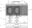
如图11所示,该装置由原边功率变换单元101(包含逆变器和LCL补偿网络),原边绕组单元102A(包含两个空间位置不同的线圈102A1、102A2),原边磁芯103,原边控制器104,副边绕组201,副边磁芯202。原副边之间有气隙301。As shown in FIG. 11 , the device consists of a primary side power conversion unit 101 (including an inverter and an LCL compensation network), a primary
如图12所示,原边线圈102A1、102A2沿x方向直线布置,互相重叠 50%;两线圈x方向宽度即横向宽度为a。线圈内激励电流的大小及相位可由控制器通过原边功率变换单元自由、灵活的调节,与负载大小以及耦合状况无关。副边绕组为盘式绕组,其中心位置设为xs。As shown in FIG. 12 , the primary coils 102A1 and 102A2 are linearly arranged along the x-direction, overlapping each other by 50%; the width of the two coils in the x-direction, that is, the lateral width is a. The size and phase of the excitation current in the coil can be freely and flexibly adjusted by the controller through the primary power conversion unit, regardless of the load size and coupling conditions. The secondary winding is a disc winding, and its center position is set to x s .
采用基于最大功率传输的激励遍历寻优方法,具体实施步骤如下:The excitation traversal optimization method based on maximum power transmission is adopted, and the specific implementation steps are as follows:
(1)保证副边负载不变,改变原边绕组内施加预激励的电流幅值、相位关系。控制器采样、处理得到不同激励下的输出功率,以最大输出功率作为指标来选取激励参数;(1) Ensure that the secondary side load remains unchanged, and change the current amplitude and phase relationship of the pre-excitation applied in the primary winding. The controller samples and processes to obtain the output power under different excitations, and selects the excitation parameters with the maximum output power as the index;
其中,步骤(1)中:对预激励绕组所施加的变激励,可采用“固定绕组电流幅值改变电流相位”或“固定绕组电流相位改变电流幅值”的搜索方法, 也可采用同时改变电流幅值、相位的方法。Among them, in step (1): for the variable excitation applied to the pre-excited winding, the search method of “fixed winding current amplitude changes current phase” or “fixed winding current phase changes current amplitude” can be used, or simultaneously changing The method of current amplitude and phase.
本例采用同时改变电流幅值和相位的激励搜索方法。绕组单元102A中仅仅包含两个线圈,故激励选择方法只需固定I1的电流大小为1A,改变I2的电流大小(0~1A)及相位(0~2π),以其中最大输出功率时的激励大小比例及相位关系,作为步骤(2)中的激励电流关系。This example uses an excitation search method that simultaneously changes the current amplitude and phase. The winding
当原边绕组的数量更多时,基于最大功率输出目标的激励搜索的控制流程图如图13所示。类似的,本步骤中对电流幅值、相位的搜索可以采用变冒泡、二分法等最优搜索方法。When the number of primary windings is larger, the control flow chart of the excitation search based on the maximum power output target is shown in Figure 13. Similarly, in this step, optimal search methods such as variable bubbling and dichotomy can be used to search for the current amplitude and phase.
(2)根据步骤(1)中得到的激励电流参数,保证施加电流比例及相位关系不变,根据输出误差反馈信号,闭环调节激励电流的幅值大小、频率、相位等满足输出电压、输出电流或输出功率的要求。(2) According to the excitation current parameters obtained in step (1), ensure that the applied current ratio and phase relationship remain unchanged, and according to the output error feedback signal, the closed-loop adjustment of the amplitude, frequency, and phase of the excitation current to meet the output voltage and output current. or output power requirements.
实施例二:Embodiment 2:
本实施例的装置构成与实施例一相同,由原边功率变换单元101(包含逆变器和补偿网络),原边绕组单元102A(包含两个空间位置不同的线圈 102A1、102A2),原边磁芯103,原边控制器104,副边绕组201,副边磁芯202。原副边之间有气隙301。副边绕组为盘式绕组,其中心位置设为xs。The structure of the device of this embodiment is the same as that of the first embodiment.
本例采用基于柔性行波磁场定向调控的的控制方法,具体实施步骤如下:This example adopts the control method based on the directional control of the flexible traveling wave magnetic field. The specific implementation steps are as follows:
(1)以原边绕组为参考,给出副边绕组的中心位置xs,此处设在[a/2,a] 内;其中,a为线圈宽度,以线圈最左侧为坐标原点;副边绕组的位置中心可由摄像头、GPS、行波测距、毫米波测距、RFID测距、超声波测距等方法得到。(1) Taking the primary winding as a reference, the center position x s of the secondary winding is given, which is set in [a/2, a] here; where a is the width of the coil, and the leftmost side of the coil is the origin of the coordinates; The position center of the secondary winding can be obtained by methods such as camera, GPS, traveling wave ranging, millimeter wave ranging, RFID ranging, and ultrasonic ranging.
(2)采用基于磁场定向调控的控制方法来快速给定电流激励关系,将磁场长(短)轴定向至盘式(DD)绕组的中心:若副边为盘式绕组,则以副边绕组的中心位置xs作为长轴位置xm来选取激励参数;若副边为DD绕组,则短轴位置xn取副边绕组中心位置xs。(2) The control method based on magnetic field oriented regulation is used to quickly set the current excitation relationship, and the long (short) axis of the magnetic field is oriented to the center of the disk (DD) winding: if the secondary side is a disk winding, the secondary side winding is used. The center position x s of , is used as the long-axis position x m to select the excitation parameter; if the secondary side is a DD winding, the short-axis position x n takes the secondary side winding center position x s .
下表为通过仿真得到的离线表。本例副边为盘式绕组,故实施长轴定向调控,不同长轴(xm)位置与实际激励电流的关系可通过查下表一、插值得到。The table below is the offline table obtained by simulation. In this example, the secondary side is a disc winding, so the long-axis directional control is implemented. The relationship between different long-axis (x m ) positions and the actual excitation current can be obtained by looking up Table 1 and interpolating.
表一Table I
(3)根据步骤(2)中得到的激励电流参数,保证施加电流比例及相位关系不变,改变激励电流的幅值大小、频率、相位等满足输出电压、输出电流或输出功率的要求。(3) According to the excitation current parameters obtained in step (2), ensure that the applied current ratio and phase relationship remain unchanged, and change the amplitude, frequency, and phase of the excitation current to meet the requirements of output voltage, output current or output power.
实施例三:Embodiment three:
本实施例的装置构成与实施例一相同,由原边功率变换单元101(包含逆变器和补偿网络),原边绕组单元102A(包含两个空间位置不同的线圈 102A1、102A2),原边磁芯103,原边控制器104,副边绕组201,副边磁芯202。原副边之间有气隙301。副边绕组为盘式绕组,其中心位置设为xs。The structure of the device of this embodiment is the same as that of the first embodiment.
不同于上例,本例副边线圈的中心位置xs未知,本例采用特定激励变化轨迹寻优-柔性行波遍历的方法,具体实施步骤如下:Different from the above example, the center position x s of the secondary coil in this example is unknown. This example adopts the method of optimization of specific excitation change trajectory - flexible traveling wave traversal. The specific implementation steps are as follows:
(1)对原边绕组施加激励构成行波磁场,根据激励的电流大小及相位关系可实时计算或查表得到相应的长轴位置xm、短轴位置xn、磁场幅度为L,控制器检测、存储每组预激励下输出功率、效率或输出电压之一,统称为Q,形成(xm,xn,Q/L2)数据;(1) Apply excitation to the primary winding to form a traveling wave magnetic field. According to the magnitude of the excitation current and the phase relationship, the corresponding long-axis position x m , short-axis position x n , and the magnetic field amplitude can be calculated in real time or look up the table to obtain the corresponding long-axis position x m , short-axis position x n , and the magnetic field amplitude is L, the controller Detect and store one of the output power, efficiency or output voltage under each group of pre-excitation, collectively referred to as Q, to form (x m , x n , Q/L 2 ) data;
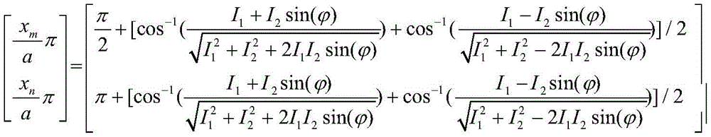
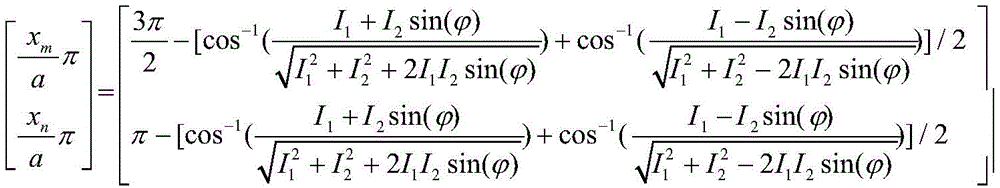
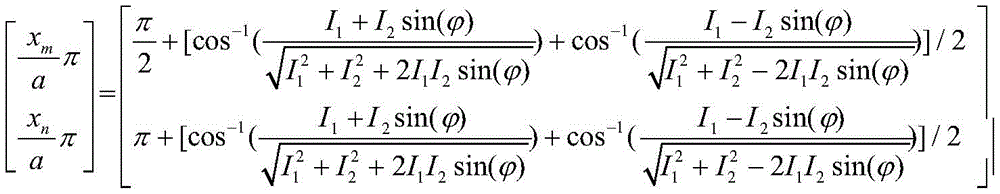
本例中,激励的电流的大小及相位关系与长轴位置xm、短轴位置xn、磁场幅度L的具体关系可根据麦克斯韦方程组、毕奥萨伐尔定律计算得到。最终化简后的表达式如下:In this example, the specific relationship between the magnitude and phase relationship of the excited current, the long-axis position x m , the short-axis position x n , and the magnetic field amplitude L can be calculated according to Maxwell's equations and Bio-Savart's law. The final simplified expression is as follows:


或:or:
当
其中I1、I2为两个线圈的电流大小,
变化激励,对Q/L2的最大值进行搜索,控制器存储最大Q/L2值所对应激励作为步骤(2)中的激励参数。Change the excitation, search for the maximum value of Q/L 2 , and the controller stores the excitation corresponding to the maximum Q/L 2 value as the excitation parameter in step (2).
(2)根据步骤(1)中得到的激励电流参数,保证施加电流比例及相位不变,根据副边输出反馈信号(输出电压、输出电流或输出功率之一),闭环调节原边激励电流幅值的大小:若反馈信号偏小则提高原边激励电流,偏大则减小输出电流,使输出满足稳压、稳流或稳功率的目标之一。(2) According to the excitation current parameters obtained in step (1), ensure that the applied current ratio and phase remain unchanged, and according to the secondary side output feedback signal (one of output voltage, output current or output power), the closed-loop adjustment of the primary side excitation current amplitude The size of the value: if the feedback signal is too small, the excitation current of the primary side will be increased, and if the feedback signal is too large, the output current will be reduced, so that the output can meet one of the goals of voltage stabilization, current stabilization or power stabilization.
实施例四:Embodiment 4:
图14为本发明实施例四绕组结构及相对位置示意图。FIG. 14 is a schematic diagram of the structure and relative positions of four windings according to an embodiment of the present invention.
与实施例一类似,本装置由原边功率变换单元101(包含逆变器和补偿网络),原边绕组单元102A(包含两个线圈102A1、102A2),原边磁芯103,原边控制器104,副边绕组201,副边磁芯202。原副边之间有气隙301。Similar to the first embodiment, the device consists of a primary side power conversion unit 101 (including an inverter and a compensation network), a primary
如图14所述原边线圈102A1、102A2x方向宽度即横向宽度为a,所施加电流的大小及相位可由控制器自由、灵活的调节,与负载以及耦合大小无关。As shown in FIG. 14 , the width of the primary coils 102A1 and 102A2x in the direction, that is, the lateral width is a, and the magnitude and phase of the applied current can be adjusted freely and flexibly by the controller, regardless of the load and coupling.
不同之处实施例一,副边绕组为DD绕组,宽度为2b,其中心位置设为xs。The difference is that in the first embodiment, the secondary winding is a DD winding, the width is 2b, and the center position thereof is set as x s .
采用基于最高效率传输的激励遍历寻优方法,具体实施步骤如下:The excitation traversal optimization method based on the most efficient transmission is adopted, and the specific implementation steps are as follows:
(1)保证副边负载不变,改变原边绕组内施加预激励的电流幅值、相位,控制器采样、处理得到不同激励下的效率。本例采用同时改变电流幅值和相位的激励搜索方法。绕组单元102A中仅仅包含两个线圈,故激励选择方法只需固定I1的电流大小为1A,改变I2的电流大小(0~1A)及相位(0~2π),以其中最大输出功率时的激励大小比例及相位关系,作为步骤(2)中的激励电流关系。(1) Ensure that the secondary side load remains unchanged, change the current amplitude and phase of the pre-excitation applied in the primary winding, and the controller samples and processes to obtain the efficiency under different excitations. This example uses an excitation search method that simultaneously changes the current amplitude and phase. The winding
当原边绕组的数量更多时,基于最大功率输出目标的激励搜索的控制流程图与图13类似,只是优化目标改为最高效率。类似的,本步骤中对电流幅值、相位的搜索可以采用变冒泡、二分法等最优搜索方法。When the number of primary windings is larger, the control flow chart of the excitation search based on the maximum power output target is similar to Fig. 13, except that the optimization target is changed to the highest efficiency. Similarly, in this step, optimal search methods such as variable bubbling and dichotomy can be used to search for the current amplitude and phase.
(2)根据步骤(1)中得到的激励电流参数,保证施加电流比例及相位关系不变,根据输出误差反馈信号,闭环调节激励电流的幅值大小、频率、相位等满足输出电压、输出电流或输出功率的要求。(2) According to the excitation current parameters obtained in step (1), ensure that the applied current ratio and phase relationship remain unchanged, and according to the output error feedback signal, the closed-loop adjustment of the amplitude, frequency, and phase of the excitation current to meet the output voltage and output current. or output power requirements.
实施例五:Embodiment 5:
本发明实施例四绕组结构及相对位置示意图同图14。The schematic diagram of the structure and relative positions of the four windings in the embodiment of the present invention is the same as that in FIG. 14 .
本实施例装置由原边功率变换单元101(包含逆变器和补偿网络),原边绕组单元102A(包含两个线圈102A1、102A2),原边磁芯103,原边控制器 104,副边绕组201,副边磁芯202。原副边之间有气隙301。副边绕组为DD 绕组,其中心位置设为xs。The device of this embodiment consists of a primary side power conversion unit 101 (including an inverter and a compensation network), a primary
本例采用柔性行波磁场定向调控的的控制方法,具体实施步骤如下:This example adopts the control method of directional regulation of the flexible traveling wave magnetic field, and the specific implementation steps are as follows:
(1)以原边绕组为参考,给出副边绕组的中心位置xs,此处设在[a/2,a] 内;其中,a为线圈宽度,以线圈最左侧为坐标原点;副边绕组的位置中心可由摄像头、GPS、行波测距、毫米波测距、RFID测距、超声波测距等方法得到。(1) Taking the primary winding as a reference, the center position x s of the secondary winding is given, which is set in [a/2, a] here; where a is the width of the coil, and the leftmost side of the coil is the origin of the coordinates; The position center of the secondary winding can be obtained by methods such as camera, GPS, traveling wave ranging, millimeter wave ranging, RFID ranging, and ultrasonic ranging.
(2)采用基于磁场定向调控的控制方法来快速给定电流激励关系,将磁场长(短)轴定向至盘式(DD)绕组的中心:若副边为盘式绕组,则以副边绕组的中心位置xs作为长轴位置xm来选取激励参数;若副边为DD绕组,则短轴位置xn取副边绕组中心位置xs。(2) The control method based on magnetic field oriented regulation is used to quickly set the current excitation relationship, and the long (short) axis of the magnetic field is oriented to the center of the disk (DD) winding: if the secondary side is a disk winding, the secondary side winding is used. The center position x s of , is used as the long-axis position x m to select the excitation parameter; if the secondary side is a DD winding, the short-axis position x n takes the secondary side winding center position x s .
下表为通过仿真得到的离线表。本例副边为DD绕组,故实施短轴定向调控,不同短轴(xn)位置与实际激励电流的关系可通过查表、插值得到。The table below is the offline table obtained by simulation. In this example, the secondary side is a DD winding, so the short-axis directional control is implemented, and the relationship between the positions of different short-axis (x n ) and the actual excitation current can be obtained through table look-up and interpolation.
表二Table II

(3)根据步骤(2)中得到的激励电流参数,保证施加电流比例及相位关系不变,根据输出误差反馈信号,闭环调节激励电流的幅值大小、频率、相位等满足输出电压、输出电流或输出功率的要求。(3) According to the excitation current parameters obtained in step (2), ensure that the applied current ratio and phase relationship remain unchanged, and according to the output error feedback signal, the closed-loop adjustment of the amplitude, frequency, and phase of the excitation current to meet the output voltage and output current. or output power requirements.
实施例六:Embodiment 6:
本发明实施例四绕组结构及相对位置示意图同图14。The schematic diagram of the structure and relative positions of the four windings in the embodiment of the present invention is the same as that in FIG. 14 .
本实施例装置由原边功率变换单元101(包含逆变器和补偿网络),原边绕组单元102A(包含两个线圈102A1、102A2),原边磁芯103,原边控制器 104,副边绕组201,副边磁芯202。原副边之间有气隙301。副边绕组为DD 绕组,其中心位置设为xs。The device of this embodiment consists of a primary side power conversion unit 101 (including an inverter and a compensation network), a primary
不同于上例,本例副边线圈的中心位置xs未知,因此本例采用特定激励变化轨迹-柔性行波遍历的方法,具体实施步骤如下:Different from the above example, the center position x s of the secondary coil in this example is unknown, so this example adopts the method of specific excitation change trajectory-flexible traveling wave traversal. The specific implementation steps are as follows:
(1)对原边绕组施加激励构成行波磁场,根据激励的电流大小及相位关系可实时计算或查表得到相应的长轴位置xm、短轴位置xn、磁场幅度为L,控制器检测、存储每组预激励下输出功率、效率或输出电压之一,统称为Q,形成(xm,xn,Q/L2)数据;(1) Apply excitation to the primary winding to form a traveling wave magnetic field. According to the magnitude of the excitation current and the phase relationship, the corresponding long-axis position x m , short-axis position x n , and the magnetic field amplitude can be calculated in real time or look up the table to obtain the corresponding long-axis position x m , short-axis position x n , and the magnetic field amplitude is L, the controller Detect and store one of the output power, efficiency or output voltage under each group of pre-excitation, collectively referred to as Q, to form (x m , x n , Q/L 2 ) data;
本例中,激励的电流的大小及相位关系与长轴位置xm、短轴位置xn、磁场幅度L的具体关系可根据麦克斯韦方程组、毕奥萨伐尔定律计算得到。最终的表达式如下:In this example, the specific relationship between the magnitude and phase relationship of the excited current, the long-axis position x m , the short-axis position x n , and the magnetic field amplitude L can be calculated according to Maxwell's equations and Bio-Savart's law. The final expression is as follows:


或:or:

其中I1、I2为两个线圈的电流大小,
将施加激励的电流大小、相位带入上式可以计算得到xm、xn以及L。Taking the magnitude and phase of the excitation current into the above equation, x m , x n and L can be calculated.
变化激励,对Q/L2的最大值进行搜索,控制器存储最大Q/L2值所对应激励作为步骤(2)中的激励参数。Change the excitation, search for the maximum value of Q/L 2 , and the controller stores the excitation corresponding to the maximum Q/L 2 value as the excitation parameter in step (2).
(2)根据步骤(1)中得到的激励电流参数,保证施加电流比例及相位不变,根据副边输出反馈信号(输出电压、输出电流或输出功率之一)调节原边激励电流值的大小:若反馈信号偏小则提高原边激励电流,偏大则减小输出电流,使输出满足稳压、稳流或稳功率的目标之一。(2) According to the excitation current parameters obtained in step (1), ensure that the applied current ratio and phase remain unchanged, and adjust the magnitude of the primary side excitation current value according to the secondary side output feedback signal (one of output voltage, output current or output power). : If the feedback signal is too small, the excitation current of the primary side will be increased, and if the feedback signal is too large, the output current will be reduced, so that the output can meet one of the goals of voltage regulation, current stabilization or power stabilization.
实施例七:Embodiment 7:
图15给出了本实施例原边绕组分布示意图;102A、102B、102C、102D、 102E、102F为多个原边绕组单元通过平移、旋转构成原边绕组的示意图。非接触电能传输装置的其余部分,包括:原边功率变换单元101(包含逆变器和补偿网络),原边磁芯103,原边控制器104,副边绕组201,副边磁芯202。原副边之间有气隙301。本实施例控制方法,同上述实施例类似,此处不再赘述。15 shows a schematic diagram of the distribution of primary windings in this embodiment; 102A, 102B, 102C, 102D, 102E, 102F are schematic diagrams of multiple primary winding units forming primary windings through translation and rotation. The rest of the contactless power transmission device includes: the primary side power conversion unit 101 (including the inverter and the compensation network), the primary side
测试实例一:Test example one:
本测试电路参照实施例一中所示电路,进行柔性行波磁场定向调控的仿真验证。非接触变压器的原边绕组、副边绕组均采用Lize线绕制,原边基本线圈单元内每个线圈的尺寸为:15cm*6cm,7匝,分布绕制;原副边磁芯采用铁氧体;原边控制器输出PWM波信号,对电流检测模块的输出信号进行采样、存储;原边功率变换单元为“全桥逆变+LCL型谐振补偿电路+电流检测模块”,功率变换单元的输出电流(即为与其相联的原边线圈的输入电流)的频率、大小、相位取决于控制器的输入PWM波占空比的频率、大小、相位;副边功率变换单元同样为谐振补偿网络,输出一个副边感应到的磁感应强度有效值大小成正比的电压,作为Q。Referring to the circuit shown in the first embodiment, this test circuit conducts simulation verification of the directional regulation of the flexible traveling wave magnetic field. The primary and secondary windings of the non-contact transformer are wound with Lize wire. The size of each coil in the primary basic coil unit is: 15cm*6cm, 7 turns, and distributed winding; the primary and secondary magnetic cores are made of ferrite. The primary side controller outputs PWM wave signal, samples and stores the output signal of the current detection module; the primary side power conversion unit is "full bridge inverter + LCL type resonance compensation circuit + current detection module", the power conversion unit The frequency, size and phase of the output current (that is, the input current of the primary coil associated with it) depend on the frequency, size and phase of the duty cycle of the input PWM wave of the controller; the secondary power conversion unit is also a resonance compensation network , output a voltage proportional to the rms value of the magnetic induction intensity induced by the secondary side, as Q.
由于原边绕组只有两个线圈,此时“柔性行波磁场”长轴移动范围为 7.5~15cm,若增加原边线圈数量,可以扩大柔性行波磁场调控区域。Since the primary winding has only two coils, the moving range of the long axis of the "flexible traveling wave magnetic field" is 7.5-15 cm. If the number of primary coils is increased, the control area of the flexible traveling wave magnetic field can be expanded.
根据(1)式离线计算得到恒定磁场幅度L激励下的不同长轴位置、短轴位置与其对应所需施加激励电流大小和相位如表一,此处不再赘述。According to the off-line calculation of formula (1), the different long-axis positions and short-axis positions under the excitation of constant magnetic field amplitude L and their corresponding required excitation current magnitudes and phases are shown in Table 1, which will not be repeated here.
本测试例副边绕组为盘式绕组,尺寸为5*5cm,共14匝;负载电阻RL固定,为5欧姆。In this test example, the secondary winding is a disc winding with a size of 5*5cm and a total of 14 turns; the load resistance R L is fixed at 5 ohms.
控制方法与实施例三类似,图16给出了本发明测试实例一特定激励变化轨迹-柔性行波遍历测试效果图(盘式绕组);不难看出,无论副边位置如何变化(在长轴移动范围内),通过柔性行波磁场激励遍历,副边绕组总能在某激励条件下取得输出电压(输出功率)极大值,从而副边在位置变动时无功率输出问题(即感应盲点)得以解决。The control method is similar to the third embodiment. Figure 16 shows the test example of the present invention, a specific excitation change trajectory-flexible traveling wave traversal test effect diagram (disc winding); it is not difficult to see that no matter how the secondary side position changes (on the long axis) Within the moving range), through the flexible traveling wave magnetic field excitation and traversal, the secondary winding can always obtain the maximum value of the output voltage (output power) under a certain excitation condition, so that the secondary side has no power output problem when the position changes (ie, the induction blind spot) be resolved.
图17给出了柔性行波磁场定向调控的实施效果仿真图。控制方法与实施例二类似,采用本发明所提方法,通过调节原边绕组的激励电流,输出电压随位置变化在开环条件下的脉动已经很小,输出功率随位置变化敏感度大为降低,提升非接触电能传输系统的实用性。Figure 17 shows the simulation diagram of the implementation effect of the directional control of the flexible traveling wave magnetic field. The control method is similar to the second embodiment. By using the method proposed in the present invention, by adjusting the excitation current of the primary winding, the pulsation of the output voltage with the position change under the open-loop condition is very small, and the sensitivity of the output power with the position change is greatly reduced. , to improve the practicability of the contactless power transmission system.
测试实例二:Test example two:
本测试电路参照实施例四中所示电路,进行柔性行波磁场激励遍历与定向调控的验证。基本电路拓扑与上例类似,差别在于此例副边绕组为DD绕组,其尺寸为(2*(5*5cm),14匝)。Referring to the circuit shown in the fourth embodiment, this test circuit conducts the verification of the flexible traveling wave magnetic field excitation traversal and directional regulation. The basic circuit topology is similar to the above example, the difference is that the secondary winding in this example is a DD winding, and its size is (2*(5*5cm), 14 turns).
由于本例副边为DD结构,因此此时柔性行波磁场激励的控制焦点为磁场短轴位置。因为本例原边绕组依然只有两个线圈,故“柔性行波磁场”短轴移动范围同样为7.5~15cm;若增加原边线圈数量,可以扩大柔性行波磁场调控区域。Since the secondary side in this example is a DD structure, the control focus of the flexible traveling wave magnetic field excitation is the position of the short axis of the magnetic field. Because the primary winding in this example still has only two coils, the short-axis movement range of the "flexible traveling wave magnetic field" is also 7.5-15 cm; if the number of primary coils is increased, the control area of the flexible traveling wave magnetic field can be expanded.
根据(1)式离线计算得到恒定磁场幅度L激励下的不同长轴位置、短轴位置与其对应所需施加激励大小和相位如表二,此处不再赘述。According to the off-line calculation of formula (1), the different long-axis positions and short-axis positions under the excitation of constant magnetic field amplitude L and their corresponding required excitation magnitudes and phases are shown in Table 2, which will not be repeated here.
图18给出了本发明测试实例二特定激励变化轨迹-柔性行波激励遍历”仿真效果图(DD绕组);不难看出,无论副边中心位置如何变化(在长轴移动范围内),通过柔性行波磁场激励遍历,副边绕组总能在某激励条件下取得输出电压(输出功率)极大值,从而DD副边在位置变动时无功率输出问题(即感应盲点)得以解决。Figure 18 shows the simulation effect diagram (DD winding) of the specific excitation change trajectory of the second test example of the present invention - flexible traveling wave excitation traversal; Flexible traveling wave magnetic field excitation traversal, the secondary winding can always obtain the maximum value of output voltage (output power) under certain excitation conditions, so that the problem of no power output (ie, induction blind spot) of the DD secondary side when the position changes can be solved.
图19给出的柔性行波磁场定向调控的实施效果仿真图同样证明了该非接触电能传输系统无感应盲点问题,并且在开环、横向位置变化75%的条件下,依然有50%的功率输出能力,提升非接触电能传输系统的实用性。The simulation diagram of the implementation effect of the directional control of the flexible traveling wave magnetic field shown in Figure 19 also proves that the non-contact power transmission system has no inductive blind spot problem, and under the condition of open loop and lateral position change of 75%, there is still 50% of the power The output capability improves the practicability of the non-contact power transmission system.
通过“输出误差反馈+闭环控制”可以实现稳压或稳流或稳功率输出。Through "output error feedback + closed-loop control", it can achieve stable voltage or stable current or stable power output.
测试例三:Test example three:
图20给出了本测试例原副边绕组结构及相对位置示意图原边。电路与上例类似,副边为DD结构,尺寸为(5*(5+5)cm)原边基本线圈单元内每个线圈的尺寸为:15cm*6cm,7匝,分布绕制。Figure 20 shows the primary and secondary winding structures and relative positions of the primary side in this test example. The circuit is similar to the above example, the secondary side is DD structure, the size is (5*(5+5)cm) The size of each coil in the basic coil unit of the primary side is: 15cm*6cm, 7 turns, distributed winding.
不同于测试例二,为了使得本发明磁场定向调控控制效果更为明显,原边绕组单元由三个线圈构成,沿直线布置,相邻两线圈重叠50%。此时“柔性行波磁场”长(短)轴的移动范围为7.5~22.5cm。若原边线圈的数量继续增加,柔性行波磁场调控区域也将同步增加。Different from Test Example 2, in order to make the magnetic field orientation regulation and control effect of the present invention more obvious, the primary winding unit is composed of three coils, arranged along a straight line, and two adjacent coils overlap by 50%. At this time, the moving range of the long (short) axis of the "flexible traveling wave magnetic field" is 7.5-22.5 cm. If the number of primary coils continues to increase, the control area of the flexible traveling wave magnetic field will also increase synchronously.
图21给出了本发明测试实例三“柔性行波激励遍历”仿真效果图(DD 绕组)。不难看出,通过柔性行波磁场激励遍历,副边绕组总能在某激励条件下实现磁场定向,即将磁场短轴定向副边线圈中心,从而取得副边输出电压极大值(Q/L2)。相比预测试实例二,本例磁场可控范围扩大,并且除去边缘外,不同位置处输出电压极大值基本相同,对位置变化的敏感度极大降低。Fig. 21 shows the simulation effect diagram (DD winding) of the third test example of the present invention "flexible traveling wave excitation traversal". It is not difficult to see that through the flexible traveling wave magnetic field excitation traversal, the secondary winding can always achieve magnetic field orientation under certain excitation conditions, that is, the short axis of the magnetic field is oriented to the center of the secondary coil, so as to obtain the maximum value of the secondary output voltage (Q/L 2 ). Compared with the pre-test example 2, the controllable range of the magnetic field in this example is expanded, and except for the edge, the maximum value of the output voltage at different positions is basically the same, and the sensitivity to position changes is greatly reduced.
图22给出了最终的柔性行波磁场定向调控的实施效果仿真图,证明了该非接触电能传输系统无感应盲点问题,并且在开环、横向位置变化50%的条件下,输出功率几乎不变,在开环、横向位置变化100%的范围内,输出功率只下降了不到15%。Figure 22 shows the simulation diagram of the final implementation effect of the directional control of the flexible traveling wave magnetic field, which proves that the non-contact power transmission system has no inductive blind spot problem, and under the condition of open loop and lateral position change of 50%, the output power is almost no change. The output power drops by less than 15% over an open-loop, lateral position change of 100%.
以上所述,仅为本发明的较佳实例而已,并非用于限定本发明的保护范围。凡在本发明的精神和原则之内,所做的任何修改、等同替换、改进等,均应包含在本发明的保护范围之内。The above descriptions are only preferred examples of the present invention, and are not intended to limit the protection scope of the present invention. Any modification, equivalent replacement, improvement, etc. made within the spirit and principle of the present invention shall be included within the protection scope of the present invention.
Claims (8)


Priority Applications (1)
| Application Number | Priority Date | Filing Date | Title |
|---|---|---|---|
| CN201810209877.XA CN108390464B (en) | 2018-03-14 | 2018-03-14 | Flexible traveling wave excitation method of non-contact electric energy transmission device |
Applications Claiming Priority (1)
| Application Number | Priority Date | Filing Date | Title |
|---|---|---|---|
| CN201810209877.XA CN108390464B (en) | 2018-03-14 | 2018-03-14 | Flexible traveling wave excitation method of non-contact electric energy transmission device |
Publications (2)
| Publication Number | Publication Date |
|---|---|
| CN108390464A CN108390464A (en) | 2018-08-10 |
| CN108390464B true CN108390464B (en) | 2020-02-14 |
Family
ID=63067308
Family Applications (1)
| Application Number | Title | Priority Date | Filing Date |
|---|---|---|---|
| CN201810209877.XA Active CN108390464B (en) | 2018-03-14 | 2018-03-14 | Flexible traveling wave excitation method of non-contact electric energy transmission device |
Country Status (1)
| Country | Link |
|---|---|
| CN (1) | CN108390464B (en) |
Families Citing this family (2)
| Publication number | Priority date | Publication date | Assignee | Title |
|---|---|---|---|---|
| CN109886051B (en) * | 2019-01-08 | 2023-10-20 | 快脉信息科技(上海)有限公司 | A vehicle positioning radio frequency identification system and its rapid inspection and positioning method |
| CN113506668B (en) * | 2021-06-24 | 2024-03-01 | 北京量子信息科学研究院 | Methods for generating uniform magnetic fields, magnetic field coils, devices, equipment and storage media |
Family Cites Families (5)
| Publication number | Priority date | Publication date | Assignee | Title |
|---|---|---|---|---|
| EP3031128B1 (en) * | 2013-08-06 | 2018-11-21 | Momentum Dynamics Corporation | A method of and apparatus for detecting coil alignment error in wireless inductive power transmission |
| CN203706812U (en) * | 2013-12-24 | 2014-07-09 | 浙江大学 | Pulse transformer based on multiple pairs of windings |
| CN204596590U (en) * | 2015-03-09 | 2015-08-26 | 南京航空航天大学 | There is the modified model non-contact transformer of secondary current phase-detection function |
| CN105896743A (en) * | 2016-04-19 | 2016-08-24 | 中南大学 | Wireless power transmission system and method |
| CN106385072B (en) * | 2016-10-11 | 2019-12-06 | 赵莹 | Radio transmission system and application device thereof |
-
2018
- 2018-03-14 CN CN201810209877.XA patent/CN108390464B/en active Active
Also Published As
| Publication number | Publication date |
|---|---|
| CN108390464A (en) | 2018-08-10 |
Similar Documents
| Publication | Publication Date | Title |
|---|---|---|
| Zhang et al. | Design methodology of free-positioning nonoverlapping wireless charging for consumer electronics based on antiparallel windings | |
| Dai et al. | Charging area determining and power enhancement method for multiexcitation unit configuration of wirelessly dynamic charging EV system | |
| CN115481526B (en) | Double-solenoid EV-DWPT system and its parameter optimization method | |
| Yao et al. | A novel misalignment tolerant magnetic coupler for electric vehicle wireless charging | |
| Shao et al. | A lightweight and robust drone MHz WPT system via novel coil design and impedance matching | |
| Yan et al. | A multiload wireless power transfer system with concentrated magnetic field for AUV cluster system | |
| CN104753152B (en) | The induction type charging system of constant current constant voltage Compound Topology | |
| CN111799895B (en) | Magnetic coupling structure and wireless power transmission system | |
| CN110422061B (en) | Wireless bidirectional electric energy conversion topology and control method thereof | |
| CN103166474B (en) | Primary side series connection secondary series and parallel non-contact resonant converter | |
| Wang et al. | Optimization design of wireless charging system for autonomous robots based on magnetic resonance coupling | |
| CN110311473B (en) | A wireless power transmission system with high anti-deviation characteristics | |
| CN112467888A (en) | Energy signal simultaneous transmission structure and dynamic wireless energy transmission system | |
| Feng et al. | A solenoid magnetic coupler and its control method for omnidirectional wireless charging of UAVs | |
| Ramezani et al. | An efficient PCB based magnetic coupler design for electric vehicle wireless charging | |
| CN108390464B (en) | Flexible traveling wave excitation method of non-contact electric energy transmission device | |
| CN112865328B (en) | Wireless power transmission system and efficiency optimization method thereof | |
| CN114899921A (en) | Wireless charging platform with expansibility | |
| CN114784993A (en) | Multi-input single-output wireless power transmission system | |
| CN108494031B (en) | Non-contact electric energy transmission device and position detection method | |
| Dai et al. | Output-voltage adaptive of omnidirectional wireless power transfer based on receivers with digital coils | |
| Matsumoto et al. | Wireless power transfer system with passive boost topology for AGVs | |
| Kathirvelu et al. | Design of Transformer for wireless power transfer in electric vehicles | |
| Wu et al. | Misalignment‐tolerant coupling cell of 2‐D modular WPT system for charging area simplified extension | |
| Yan et al. | Efficiency optimization of omnidirectional multiload wireless power transfer system based on magnetic vector regulation |
Legal Events
| Date | Code | Title | Description |
|---|---|---|---|
| PB01 | Publication | ||
| PB01 | Publication | ||
| SE01 | Entry into force of request for substantive examination | ||
| SE01 | Entry into force of request for substantive examination | ||
| GR01 | Patent grant | ||
| GR01 | Patent grant |