The benefit under 35u.s.c. § 119(e) of U.S. provisional application No. 62/265,830, filed 2015, 12, 10, and entitled "SYSTEM AND METHOD FOR a REMOVABLE SYRINGE micropump," the disclosure of which is incorporated herein by reference.
Detailed Description
Before proceeding with the detailed description, it is to be understood that the present teachings are by way of example only and not limitation. The concepts herein are not limited to use or application with a particular system or method for a removable syringe micropump having a volute spring. Thus, while the instrumentalities described herein are for convenience of explanation regarding the illustration and description of exemplary embodiments, it is to be understood and appreciated that the principles herein may be equally applied to other types of systems and methods involving micropumps and, in particular, removable syringe micropumps.
The present invention is described in relation to the preferred embodiments in the following description with reference to the figures, in which like numbers represent the same or similar elements. Further, with respect to the numbering of the same or similar elements, it will be appreciated that the preceding values identify the drawing in which the element was first identified and described, e.g., element 100 appears first in FIG. 1.
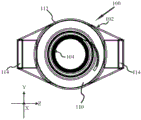
Turning now to fig. 1, a removable syringe micropump 100, hereinafter referred to as RSMP100, is shown in exploded form with a volute spring. As shown, RSMP100 is primarily comprised of a pump housing 102 and a volute spring 104. As will be more fully appreciated from the description below, since RSMP100 is removable, it may be provided separately to the patient or to the party desiring to use the syringe micropump, and may be reused by the same party or a different party and with the same syringe or a different syringe.
To facilitate the description of the systems and methods for this RSMP100, the orientation of the RSMP100 as presented in the figures refers to a coordinate system in which the three axes are orthogonal to each other as shown in fig. 1. The axes intersect each other at the origin of the coordinate system, which is selected to be the center of RSMP100, however, for clarity and ease of illustration, the axes are shown in all figures as being offset from their actual positions.
The pump housing 102 provides a first end 106, which first end 106 may be at least partially established by an enhancement base 108. Opposite the first end 106 is an attachment end 110, and there is at least one sidewall 112 between the first end and the attachment end. For at least one embodiment, the attachment end 110 has a set of flanges 114.
As shown, for at least one embodiment, the pump housing 102 is cylindrical. Of course, for other embodiments, it may be desirable to provide the pump housing 102 in a configuration having a square, hexagonal, or other geometric cross-section in addition to circular.
Within pump housing 102 and adjacent first end 106 is constructed and arranged to receive and engage scroll spring 104 to a base 116 of pump housing 102. For at least one embodiment, the base 116 has a receiving recess 118 constructed and arranged to receive the tip of the volute spring 104. Further, in various embodiments, the base 116 may be a specific structure or surface to which the volute spring 104 is attached, or a generalized region of the pump housing configured to receive the end of the volute spring 104. In other words, the base 116 is the portion of the pump housing 102 to which the tip of the volute spring 104 is attached and away from which the volute spring extends when tension is released.
As shown in fig. 1, the volute spring 104 is in its extended/relaxed position. Since the volute spring 104 is a type of compression spring, it is to be understood and appreciated that the coils 120 of the volute spring 104 are concentrically positioned when compressed such that the height of the volute spring 104 compressed under tension is effectively the same height as any given coil 120. Further, the height of the compressed volute spring 104 when under tension is substantially less than the height of the volute spring 104 when extended.
Further, because the coils 120 of the volute spring 104 are concentrically disposed when compressed, the relative change in size from the compressed state to the extended state is much greater than that typically achieved with conventional coil springs, where the coils are positioned one above the other when compressed. While the present illustration and description refers to a single volute spring 104, it is to be understood and appreciated that for at least one alternative embodiment, a plurality of nested volute springs 104 may be employed.
For at least one embodiment, the first or proximal end 122 of the volute spring 104 is disposed in the receiving recess 118 of the base 116 as mentioned above. Thus, the distal end 124 of the volute spring 104 moves away from the base 116 and pump housing 102 as a whole when the tension in the volute spring 104 is released as the volute spring 104 transitions from the compressed first position to the relaxed/extended second position.
Adjacent RSMP100 in fig. 1 is a syringe 126, the syringe 126 having a barrel 128 defining a chamber 130 between a nozzle 132 and a set of finger grips 134 adjacent an open end 136 of the syringe 126. The plunger seal 138 is understood and appreciated as a movable element within the barrel 128, the plunger seal 138 being slidable along the interior of the barrel 128 while maintaining a seal.
In some constructions (such as that shown), the plunger seal 138 may be comprised of a piston element 140, the piston element 140 being coupled to a sealing element 142, generally comprised of rubber, silicone, or other semi-elastomeric material that may be used to provide a movable seal. For purposes of this discussion, the plunger seal 138, whether formed of one or more components, is understood to be such an element.
Also shown in fig. 1 is the plunger 144 removed from the syringe 126 and disconnected from the plunger seal 138. When attached, the plunger 144 may be used by an operator engaging his or her fingers around the finger grip 134 to depress the plunger seal 138 toward the nozzle 132 from a position within the chamber 130 over the nozzle 132. The reverse is true. The plunger 144 may be used by an operator to pull the plunger seal 138 away from the nozzle 132.
As can be appreciated in fig. 1, the plunger 144 has an alignment specific attachment element 152, such as a rectangular flange. Likewise, the plunger seal 138 has a corresponding mating attachment element 154, such as a rectangular receptacle. Thus, for at least one embodiment, when the plunger attachment element 152 is disposed within the plunger seal mating attachment element 154, the plunger 144 engages and disengages the plunger seal 138 by twisting. For yet another embodiment, not shown, the plunger 144 has a push or pull mechanism that releases an attachment element coupled to the plunger seal 138.
When the plunger 144 is attached to the plunger seal 138, the operator may pull the plunger seal 138 away from the nozzle 132e by the plunger 144 toward the finger grip 134. This action creates a vacuum within barrel 128 and allows syringe 126 to draw in fluid solution or gas through nozzle 132 and thus substantially fill barrel 128 between nozzle 132 and plunger seal 138.
With respect to fig. 1, it will be appreciated that the plunger 144 is substantially longer in length than the barrel 128 of the syringe 126, as shown. However, because the plunger 144 is removable, when the plunger seal 138 has been disposed adjacent the finger grip 134, or whatever other desired location within the barrel 128 is deemed appropriate, and the plunger 144 is removed, the effective length of the syringe 126 is approximately that of the barrel 128 and nozzle 132.
Returning to the RSMP100, and more particularly the attachment end 110 of the pump housing 102, it will be appreciated that the flange 114 is constructed and arranged to engage the finger grip 134 of the syringe 126. Further, when the pump housing 102 is disposed over the open end 136 of the syringe 126 adjacent the finger grips 134, the operator rotates the components relative to one another such that the finger grips 134 are engaged by the flange 114. In the same manner, finger grips 134 provide a lever action point for the fingers of a human operator; finger grip 134 provides a feed bar point of action for RSMP 100.
For at least one embodiment, the flange 114 may be provided with a substantially sized and shaped inset recess of the finger grip 134 such that when rotated into position, the finger grip 134 is received by the recess and thereby locks the RSMP100 in place. One or more additional springs (not shown) may provide a separation force, as between the pump housing 102 and the syringe 126, to further engage the finger grip 134 with the flange recess and prevent accidental separation of the RSMP100 from the syringe 126.
It will also be appreciated that the distal end 124 of the volute spring 104 is constructed and arranged to engage the plunger seal 138 of the engaged syringe 126. In alternative embodiments, the distal end 122 may further include a flange, washer, or other structure to aid in uniform transfer of force from the volute spring 104 to the plunger seal 138.
When the compressed scroll spring 104 is released, the release of tension expands the scroll spring 104 outwardly from the pump housing 102 and against the plunger seal 138. When the pump housing 102 is locked in place by the flange 114 against the finger grip 134, expansion of the volute spring 104 from its compressed first position to a relaxed/extended second position, the distal end 122 drives the plunger seal 138 toward the nozzle 128.
Further, it is to be understood and appreciated that the volute spring 104 is advantageously operating in place of the conventional plunger 144.
As further shown in fig. 1, the pump housing 102 has a dimension HD 146 along the sidewall 112. This dimension HD 146 is slightly larger than the width dimension W148 of the coil 102 of the volute spring 104. Accordingly, the pump housing 102 of the RSMP100 may be substantially more compact than conventional pumps that have been constructed to receive and actuate the conventional plunger 144 and syringe 126.
More specifically, it is to be understood and appreciated that the sidewall 112 is sized to be smaller than the length of the syringe 126. For at least one embodiment, the sidewall 112 of the pump housing 102 is sized less than half the length of the syringe 126. For at least one embodiment, the sidewall 112 of the pump housing 102 is sized to be less than one-third the length of the syringe 126. For yet at least one embodiment, the sidewall 112 of the pump housing 102 is sized less than one-quarter of the length of the syringe 126. Furthermore, it is to be understood and appreciated that the RSMP100 is compact and, when attached, does not significantly increase the overall length of the syringe 126.
Further, when the plunger 144 is removed, the RSMP100 coupled to the syringe 126 may be disposed in a person's pocket, purse, backpack, or other space and in substantially any orientation during an infusion therapy session. Because the movement of the volute spring 104 is entirely within the pump housing 102 and barrel 128 of the syringe 126, it does not catch on or by foreign objects.
Although the RSMP100 may advantageously operate without the use of the plunger 144, for at least one embodiment, the RSMP100, and more particularly the pump housing 102, provides an intermediate aperture 150 such that the plunger 144 may pass directly through the RSMP100 and engage the plunger seal 138. Accordingly, the plunger 144 may be used to reset the RSMP100 by using the plunger seal 138 to draw the volute spring 104 back to its compressed first position, ready to be used again to drive the plunger seal 138 forward.
Further, in at least one example, a removable plunger 144 may be used to prime and prepare the syringe 126 prior to attachment of the RSMP 100. In another example, the RSMP removable plunger 144 may be removed, the RSMP100 attached to the syringe 126, and the removable plunger 144 inserted through the aperture 150 to engage the plunger seal 138 and prime the syringe 126 for its initial use or subsequent reuse. And for another example, a plunger may be disposed through the aperture 150 of the RSMP100 for storage.
For at least one embodiment, the RSMP100 may further comprise a volute spring 104 limiter 156, the limiter 156 being constructed and arranged to limit the volute spring 104 when the volute spring 104 has been returned to the first position. For the exemplary embodiment shown in fig. 1, the exemplary limiter 156 is shown as a push button that operatively couples an inner lever of the slide pin to engage an edge of the volute spring 104 adjacent the distal end 122. The sliding pin may optionally engage a groove or slot in the side of the volute spring 104. Alternatively, the limiter 156 may be an adjustable friction ring that tightens around the volute spring 104. It is of course to be understood and appreciated that various mechanical elements may be employed as the limiter 156 of the volute spring 104 within the teachings of the present disclosure.
Fig. 2A, 2B, and 2C provide further illustration to aid in understanding and appreciate the advantageous properties of the volute spring 104 as used in the RSMP 100. More specifically, in fig. 2A, the volute spring 104 is shown in its relaxed/extended second position 200.
By applying a compressive force 202, the volute spring 104 is compressed such that the coils 120 are concentrically placed one above the other, as shown in FIG. 2B. This is the compressed first position 204 of the volute spring 104. In this state, the volute spring 104 is under tension, as indicated by arrow 206. More specifically, the tension established is an expanding force 206 that drives the volute spring 104 back to its relaxed/extended second position 200 once the volute spring 104 is released from the compressed first position 204.
As shown in fig. 2C, the nature of the coil 120 of the volute spring is such that the volute spring 104 has an open center 208. Thus, the open center 208 allows the volute spring 104 to allow the plunger 144 to pass through the volute spring 104 and engage the plunger seal 138 when the plunger is disposed through the aperture 150 of the pump housing 102.
Further, for at least one embodiment, the volute spring 104 is selected to have a tension associated with dispensing solution from the syringe 126 over a predetermined period of time. In other words, a first volute spring 104 having a first tension may be used to dispense solution at a first rate, while a second volute spring 104 having a second tension less than the first tension may be used to dispense the same solution at a second rate that is lower than the first rate.
For at least one embodiment, the volute spring 104 is selected to have a relaxed/extended second position 200 equal to or slightly beyond the length of the barrel 128 in order to ensure that all of the solution within the barrel 128 of the syringe 126 is dispensed. It is also to be understood and appreciated that the volute spring 104 need not always be compressed back to the first position 204 as shown.
In practice, the volute spring 104 may be compressed so as to substantially return a substantial portion of the volute spring 104 to the pump housing 102, with the distal end 122 extending from the pump housing 102. Further, the compressed first position 204 is understood and appreciated as the initial position of the volute spring 104 relative to the pump housing 102 of the RSMP100 before the RSMP100 is activated to drive the plunger seal 138 toward the nozzle 132.
Further, the volute spring 104 limiter 156 allows the RSMP100 to be attached to the syringe 126, but it is desirable that activation of the volute spring 104 be delayed until such time as infusion of the solution within the barrel 128 of the syringe 126.
Fig. 3A, 3B, 3C, and 3D provide front, side, bottom, and perspective views, respectively, of RSMP 100. For each illustration as shown, the volute spring 104 has been shown in a compressed first position within the pump housing 102. In fig. 3A, the width W148 of the volute spring 104 relative to the height HD 146 of the pump housing 102 may also be more fully appreciated. Indeed, with respect to fig. 3A, 3B, 3C, and 3D, the removable nature of RSMP100 may be further appreciated that elements of RSMP100 may be realized as comprising distinct RSMP100 in the absence of a syringe.
In summary, for at least one embodiment, provided is an RSMP100 comprising: a pump housing 102, said pump housing 102 having a first end 106 and an attachment end 110 opposite thereto and at least one sidewall 112 therebetween, said housing having a base 116 adjacent to the first end 106, and said attachment end 110 having an attachment 114 constructed and arranged to temporarily engage a syringe 126; a volute spring 104, the volute spring 104 nested within the housing and attached adjacent to the base 116, the volute spring 104 having a compressed first position 204, wherein the coils 120 of the volute spring 104 are concentrically arranged such that the initial height of the volute spring 104 is equal to the width of the coils 120 under tension, the volute spring 104 has an extended second position 200, wherein the release of the tension generally extends the volute spring 104 away from the pump housing 102, the volute spring 104 having a diameter preselected to pass within the barrel 128 of the engaged syringe 126, the volute spring 104 further having a distal end 12 constructed and arranged to engage the plunger seal 138 of the engaged syringe 126, wherein release of the tension between the first position 204 and the second position 200 allows the distal end 124 of the volute spring 104 to move the plunger seal 138 toward the nozzle 132 of the syringe 126.
Further, another embodiment may be summarized as RSMP100, comprising: a cylindrical pump housing 102, said cylindrical pump housing 102 having a first end 106 with a base 116 and an attachment end 110 opposite thereto, the attachment end providing at least one flange constructed and arranged to temporarily engage a set of finger grips 134 provided by a syringe 126 to which the cylindrical pump housing 102 may be temporarily attached, said cylindrical pump having a central longitudinal axis; a volute spring 104, said volute spring 104 disposed within the pump housing 102 adjacent the base 116 and about the longitudinal axis, the volute spring 104 being axially compressible to fit within the cylindrical pump when the distal end 124 of the volute spring 104 is compressed to provide a compressed first position 204, the volute spring 104 having a height approximately the same as the length of the cylindrical pump housing 102, the volute spring 104 further selected to have a diameter sufficient to slide within the barrel 128 of the syringe 126, the distal end 124 of the volute spring 104 being constructed and arranged to engage the plunger seal 138 of the engaged syringe 126 when the volute spring 104 transitions to an extended second position 200.
Fig. 4A and 4B provide an assembled perspective view and corresponding cross-sectional view of RSMP100 engaged to injector 126 in accordance with at least one embodiment. Further, in fig. 4A, the RSMP100 has been disposed on the syringe 126 such that the flange 114 of the pump housing 102 has engaged the finger grip 134 of the syringe 126. With respect to fig. 4A, it should also be appreciated that the overall length of the injector 126 with the RSMP100 attached is only slightly longer than the length of the injector 126 itself.
Moreover, with respect to fig. 4A, which is an external view, it should also be appreciated that the state of the volute spring 104 within the assembly of the RSMP100 and the syringe 126 is not necessarily apparent — particularly if the barrel 128 of the syringe 126 is opaque.
In fig. 4B, a cross-sectional view is presented along longitudinal axis 400, it can be seen that the volute spring 104 has expanded from its compressed first position within the pump housing 102 to a relaxed second position, and the application of the force released during this change of position has driven the plunger seal 138 down the length of barrel 128 such that the plunger seal 138 is now adjacent nozzle 132.
Fig. 5A and 5B provide similar assembled perspective views and corresponding cross-sectional views of RSMP100 engaged to syringe 126, and now further illustrate plunger 144 as disposed through aperture 150 of pump housing 102, in accordance with at least one embodiment. As mentioned above, it is to be understood and appreciated that during typical use of the RSMP100, the plunger will be removed in order to minimize the total space required for operation, as well as to eliminate the opportunity for the plunger to be restricted or otherwise impeded by some foreign object, which in turn will impede operation of the RSMP 100.
As shown in fig. 5A and 5B, a plunger 144 may be disposed through RSMP100 to engage plunger seal 138 and draw it back from nozzle 132 toward finger grip 134. Accordingly, the plunger 144 may be used to reset the RSMP100 by returning the volute spring to its compressed first position. Further, as with conventional syringes, drawing plunger 144 rearward creates a vacuum within the chamber of syringe 126 so that fluid can be drawn into syringe 126 from some reservoir. Additionally, plunger 144 may be used to prime (prime) syringe 126 and reset RSMP 100.
Fig. 6A, 6B, 6C, and 6D provide side cross-sectional views illustrating RSMP100 in use. More specifically, fig. 6A corresponds to an initial state of the RSMP100 when attached to the syringe 126, wherein the plunger seal 138 is disposed proximate the finger grip 134. In actual use, a fluid or medicament, such as for infusion therapy, represented by dots 600, will be present in chamber 130 between plunger seal 138 and nozzle 132.
In fig. 6B, RSMP100 has been activated such that scroll spring 104 has been released from its compressed/tensioned first position and has engaged plunger seal 138 to move it approximately one third of the way along barrel 128 toward nozzle 132, thereby dispensing fluid 600. In actual use, the syringe 126, and more particularly the nozzle 132, will be coupled to tubing or other delivery conduit that is not shown to simplify the illustration.
In fig. 6C, the RSMP100 has continued operation such that the volute spring 104 has now driven approximately two-thirds of the way along the barrel 128 toward the nozzle 132, thereby further dispensing the fluid 600.
And in fig. 6D, the RSMP100 has ceased operation because the volute spring 104 has now substantially driven the plunger seal 138 to the end of the barrel 128 such that substantially all of the fluid has now been dispensed from the syringe 126.
6A-6D, expansion of the volute spring 104, and therefore advancement of the plunger seal 138, will continue until the volute spring 104 has reached its extended/relaxed second position, the plunger seal 138 has encountered the end of the barrel 128, or a restraining mechanism (not shown) is engaged to prevent further expansion of the volute spring 104. For at least one embodiment, the volute spring 104 is selected to have a fully extended state that is equal to or slightly beyond the length of the barrel 128 in order to ensure that all of the solution within the barrel 128 of the syringe 126 is dispensed.
Further, as is particularly apparent in fig. 6A-6D, the movement of the volute spring 104 occurs entirely within the RSMP100 and the barrel 128 of the syringe 126. Furthermore, there is no external change in the size of the coupled RSMP100 and syringe 126 during operation, e.g., the plunger 144 is not jammed or disturbed. It should also be noted that while exemplary fig. 6A and 6D have illustrated RSMP100 being used to drive plunger seal 138 from a starting point adjacent finger grip 134 to the end of barrel 128 adjacent nozzle 132 (e.g., a full syringe), it is to be understood and appreciated that RSMP100 is equally applicable and suitable for use with syringes having an initial starting volume less than a full syringe.
This small compact nature of the RSMP100 and syringe 126 may facilitate instillation when the combined structure is disposed within a pocket. Further, since the operation of the volute spring 104 is a mechanical release of tension, it is understood and appreciated that the operation of the RSMP100 is independent of orientation.
For shipping and transport, the RSMP100 may be attached to the syringe 126 barrel 128, and the plunger 144 inserted through the aperture 150 of the pump housing 102 and seated with the plunger seal 138, which plunger seal 138 in turn is disposed against the bottom of the syringe 126 adjacent the nozzle 132. Injector 126 and RSMP100 are therefore compact systems. When use of RSMP100 is desired, plunger 144 may be withdrawn to pull plunger seal 138 rearward and fill barrel 128 with the desired ease for subsequent infusion in the process.
When the plunger seal 128 is properly positioned at a point sufficient to provide the desired amount of solution, the plunger 144 may be separated from the plunger seal 138 and discarded. Once again, RSMP100 and syringe 126 are an advantageously compact system, with plunger 144 now removed. As before, the operation of the volute spring 104 is entirely internal, so that there is no external dimensional change.
With respect to the above description of RSMP100, the removable nature of RSMP100 mentioned above may now be fully appreciated. In fact, RSMP100 is not only removable, but also reusable. RSMP100 can thus be reset and attached to a new syringe that has been filled and delivered without a syringe pump, thereby allowing savings in a range of categories including, but not limited to, education of shipping, storage, materials and use. Once the patient or party completes the RSMP100, the RSMP100 may also be recycled back to the new party. In addition, RSMP100 may be shared by multiple parties, apparently using RSMP100 at different times.
Having described embodiments for RSMP100, further embodiments involving at least one method 700 of using RSMP100 will now be discussed with respect to the above illustration and in particular fig. 7. It should be appreciated that the described method 700 need not be performed in the order described herein, but rather this is merely an example of one method of using RSMP 100.
Generally, at block 702, the method 700 is used to begin with providing a syringe 126 having a barrel 128 extending between a nozzle 132 and a set of finger grips 134. For simplicity, it will be assumed that the plunger seal 138 is disposed within the barrel 128 and adjacent the finger grip 134 with the solution disposed between the plunger seal 138 and the nozzle 132. Further, this is the syringe 126 in a ready state for use in providing a solution for infusion into a patient.
Block 704, the RSMP100 is then provided, the RSMP100 having a set of flanges 114 constructed and arranged to engage the finger grip 134. Furthermore, an RSMP100 as described above is provided, said RSMP100 being mainly constituted by a pump housing 102 and a volute spring 104. At block 706, method 700 continues with coupling RSMP100 to syringe 126 by disposing flange 114 around finger grip 134.
The volute spring 104 is then released to engage the plunger seal 138 of the syringe 126 and drive the plunger seal 138 toward the nozzle 132, thus dispensing the solution from the syringe 126, block 708.
Changes may be made in the above methods, systems and structures without departing from the scope thereof. It is therefore to be noted that the subject matter contained in the above description and/or shown in the accompanying drawings is to be interpreted as illustrative and not in a limiting sense. Indeed, many other embodiments are possible and possible as will be apparent to those skilled in the art. The appended claims are not to be limited by or to the embodiments discussed herein, but are to be limited only by the terminology and equivalents thereof.