CN108263208B - Locking device, power assembly, power transmission system and vehicle - Google Patents
Locking device, power assembly, power transmission system and vehicle Download PDFInfo
- Publication number
- CN108263208B CN108263208B CN201611265803.5A CN201611265803A CN108263208B CN 108263208 B CN108263208 B CN 108263208B CN 201611265803 A CN201611265803 A CN 201611265803A CN 108263208 B CN108263208 B CN 108263208B
- Authority
- CN
- China
- Prior art keywords
- flange
- shaft
- power assembly
- locking device
- powertrain
- Prior art date
- Legal status (The legal status is an assumption and is not a legal conclusion. Google has not performed a legal analysis and makes no representation as to the accuracy of the status listed.)
- Active
Links
Images


Classifications
-
- F—MECHANICAL ENGINEERING; LIGHTING; HEATING; WEAPONS; BLASTING
- F16—ENGINEERING ELEMENTS AND UNITS; GENERAL MEASURES FOR PRODUCING AND MAINTAINING EFFECTIVE FUNCTIONING OF MACHINES OR INSTALLATIONS; THERMAL INSULATION IN GENERAL
- F16H—GEARING
- F16H1/00—Toothed gearings for conveying rotary motion
- F16H1/02—Toothed gearings for conveying rotary motion without gears having orbital motion
- F16H1/20—Toothed gearings for conveying rotary motion without gears having orbital motion involving more than two intermeshing members
- F16H1/22—Toothed gearings for conveying rotary motion without gears having orbital motion involving more than two intermeshing members with a plurality of driving or driven shafts; with arrangements for dividing torque between two or more intermediate shafts
-
- B—PERFORMING OPERATIONS; TRANSPORTING
- B60—VEHICLES IN GENERAL
- B60K—ARRANGEMENT OR MOUNTING OF PROPULSION UNITS OR OF TRANSMISSIONS IN VEHICLES; ARRANGEMENT OR MOUNTING OF PLURAL DIVERSE PRIME-MOVERS IN VEHICLES; AUXILIARY DRIVES FOR VEHICLES; INSTRUMENTATION OR DASHBOARDS FOR VEHICLES; ARRANGEMENTS IN CONNECTION WITH COOLING, AIR INTAKE, GAS EXHAUST OR FUEL SUPPLY OF PROPULSION UNITS IN VEHICLES
- B60K17/00—Arrangement or mounting of transmissions in vehicles
- B60K17/04—Arrangement or mounting of transmissions in vehicles characterised by arrangement, location or kind of gearing
- B60K17/06—Arrangement or mounting of transmissions in vehicles characterised by arrangement, location or kind of gearing of change-speed gearing
- B60K17/08—Arrangement or mounting of transmissions in vehicles characterised by arrangement, location or kind of gearing of change-speed gearing of mechanical type
-
- B—PERFORMING OPERATIONS; TRANSPORTING
- B60—VEHICLES IN GENERAL
- B60K—ARRANGEMENT OR MOUNTING OF PROPULSION UNITS OR OF TRANSMISSIONS IN VEHICLES; ARRANGEMENT OR MOUNTING OF PLURAL DIVERSE PRIME-MOVERS IN VEHICLES; AUXILIARY DRIVES FOR VEHICLES; INSTRUMENTATION OR DASHBOARDS FOR VEHICLES; ARRANGEMENTS IN CONNECTION WITH COOLING, AIR INTAKE, GAS EXHAUST OR FUEL SUPPLY OF PROPULSION UNITS IN VEHICLES
- B60K1/00—Arrangement or mounting of electrical propulsion units
- B60K1/02—Arrangement or mounting of electrical propulsion units comprising more than one electric motor
-
- B—PERFORMING OPERATIONS; TRANSPORTING
- B60—VEHICLES IN GENERAL
- B60K—ARRANGEMENT OR MOUNTING OF PROPULSION UNITS OR OF TRANSMISSIONS IN VEHICLES; ARRANGEMENT OR MOUNTING OF PLURAL DIVERSE PRIME-MOVERS IN VEHICLES; AUXILIARY DRIVES FOR VEHICLES; INSTRUMENTATION OR DASHBOARDS FOR VEHICLES; ARRANGEMENTS IN CONNECTION WITH COOLING, AIR INTAKE, GAS EXHAUST OR FUEL SUPPLY OF PROPULSION UNITS IN VEHICLES
- B60K17/00—Arrangement or mounting of transmissions in vehicles
- B60K17/02—Arrangement or mounting of transmissions in vehicles characterised by arrangement, location, or kind of clutch
-
- B—PERFORMING OPERATIONS; TRANSPORTING
- B60—VEHICLES IN GENERAL
- B60K—ARRANGEMENT OR MOUNTING OF PROPULSION UNITS OR OF TRANSMISSIONS IN VEHICLES; ARRANGEMENT OR MOUNTING OF PLURAL DIVERSE PRIME-MOVERS IN VEHICLES; AUXILIARY DRIVES FOR VEHICLES; INSTRUMENTATION OR DASHBOARDS FOR VEHICLES; ARRANGEMENTS IN CONNECTION WITH COOLING, AIR INTAKE, GAS EXHAUST OR FUEL SUPPLY OF PROPULSION UNITS IN VEHICLES
- B60K17/00—Arrangement or mounting of transmissions in vehicles
- B60K17/04—Arrangement or mounting of transmissions in vehicles characterised by arrangement, location or kind of gearing
- B60K17/043—Transmission unit disposed in on near the vehicle wheel, or between the differential gear unit and the wheel
-
- B—PERFORMING OPERATIONS; TRANSPORTING
- B60—VEHICLES IN GENERAL
- B60K—ARRANGEMENT OR MOUNTING OF PROPULSION UNITS OR OF TRANSMISSIONS IN VEHICLES; ARRANGEMENT OR MOUNTING OF PLURAL DIVERSE PRIME-MOVERS IN VEHICLES; AUXILIARY DRIVES FOR VEHICLES; INSTRUMENTATION OR DASHBOARDS FOR VEHICLES; ARRANGEMENTS IN CONNECTION WITH COOLING, AIR INTAKE, GAS EXHAUST OR FUEL SUPPLY OF PROPULSION UNITS IN VEHICLES
- B60K17/00—Arrangement or mounting of transmissions in vehicles
- B60K17/34—Arrangement or mounting of transmissions in vehicles for driving both front and rear wheels, e.g. four wheel drive vehicles
-
- B—PERFORMING OPERATIONS; TRANSPORTING
- B60—VEHICLES IN GENERAL
- B60K—ARRANGEMENT OR MOUNTING OF PROPULSION UNITS OR OF TRANSMISSIONS IN VEHICLES; ARRANGEMENT OR MOUNTING OF PLURAL DIVERSE PRIME-MOVERS IN VEHICLES; AUXILIARY DRIVES FOR VEHICLES; INSTRUMENTATION OR DASHBOARDS FOR VEHICLES; ARRANGEMENTS IN CONNECTION WITH COOLING, AIR INTAKE, GAS EXHAUST OR FUEL SUPPLY OF PROPULSION UNITS IN VEHICLES
- B60K7/00—Disposition of motor in, or adjacent to, traction wheel
- B60K7/0007—Disposition of motor in, or adjacent to, traction wheel the motor being electric
-
- F—MECHANICAL ENGINEERING; LIGHTING; HEATING; WEAPONS; BLASTING
- F16—ENGINEERING ELEMENTS AND UNITS; GENERAL MEASURES FOR PRODUCING AND MAINTAINING EFFECTIVE FUNCTIONING OF MACHINES OR INSTALLATIONS; THERMAL INSULATION IN GENERAL
- F16D—COUPLINGS FOR TRANSMITTING ROTATION; CLUTCHES; BRAKES
- F16D23/00—Details of mechanically-actuated clutches not specific for one distinct type
- F16D23/02—Arrangements for synchronisation, also for power-operated clutches
-
- F—MECHANICAL ENGINEERING; LIGHTING; HEATING; WEAPONS; BLASTING
- F16—ENGINEERING ELEMENTS AND UNITS; GENERAL MEASURES FOR PRODUCING AND MAINTAINING EFFECTIVE FUNCTIONING OF MACHINES OR INSTALLATIONS; THERMAL INSULATION IN GENERAL
- F16D—COUPLINGS FOR TRANSMITTING ROTATION; CLUTCHES; BRAKES
- F16D27/00—Magnetically- or electrically- actuated clutches; Control or electric circuits therefor
- F16D27/10—Magnetically- or electrically- actuated clutches; Control or electric circuits therefor with an electromagnet not rotating with a clutching member, i.e. without collecting rings
- F16D27/118—Magnetically- or electrically- actuated clutches; Control or electric circuits therefor with an electromagnet not rotating with a clutching member, i.e. without collecting rings with interengaging jaws or gear teeth
-
- F—MECHANICAL ENGINEERING; LIGHTING; HEATING; WEAPONS; BLASTING
- F16—ENGINEERING ELEMENTS AND UNITS; GENERAL MEASURES FOR PRODUCING AND MAINTAINING EFFECTIVE FUNCTIONING OF MACHINES OR INSTALLATIONS; THERMAL INSULATION IN GENERAL
- F16D—COUPLINGS FOR TRANSMITTING ROTATION; CLUTCHES; BRAKES
- F16D27/00—Magnetically- or electrically- actuated clutches; Control or electric circuits therefor
- F16D27/12—Clutch systems with a plurality of electro-magnetically-actuated clutches
-
- B—PERFORMING OPERATIONS; TRANSPORTING
- B60—VEHICLES IN GENERAL
- B60K—ARRANGEMENT OR MOUNTING OF PROPULSION UNITS OR OF TRANSMISSIONS IN VEHICLES; ARRANGEMENT OR MOUNTING OF PLURAL DIVERSE PRIME-MOVERS IN VEHICLES; AUXILIARY DRIVES FOR VEHICLES; INSTRUMENTATION OR DASHBOARDS FOR VEHICLES; ARRANGEMENTS IN CONNECTION WITH COOLING, AIR INTAKE, GAS EXHAUST OR FUEL SUPPLY OF PROPULSION UNITS IN VEHICLES
- B60K17/00—Arrangement or mounting of transmissions in vehicles
- B60K17/34—Arrangement or mounting of transmissions in vehicles for driving both front and rear wheels, e.g. four wheel drive vehicles
- B60K17/354—Arrangement or mounting of transmissions in vehicles for driving both front and rear wheels, e.g. four wheel drive vehicles having separate mechanical assemblies for transmitting drive to the front or to the rear wheels or set of wheels
-
- B—PERFORMING OPERATIONS; TRANSPORTING
- B60—VEHICLES IN GENERAL
- B60K—ARRANGEMENT OR MOUNTING OF PROPULSION UNITS OR OF TRANSMISSIONS IN VEHICLES; ARRANGEMENT OR MOUNTING OF PLURAL DIVERSE PRIME-MOVERS IN VEHICLES; AUXILIARY DRIVES FOR VEHICLES; INSTRUMENTATION OR DASHBOARDS FOR VEHICLES; ARRANGEMENTS IN CONNECTION WITH COOLING, AIR INTAKE, GAS EXHAUST OR FUEL SUPPLY OF PROPULSION UNITS IN VEHICLES
- B60K17/00—Arrangement or mounting of transmissions in vehicles
- B60K17/34—Arrangement or mounting of transmissions in vehicles for driving both front and rear wheels, e.g. four wheel drive vehicles
- B60K17/356—Arrangement or mounting of transmissions in vehicles for driving both front and rear wheels, e.g. four wheel drive vehicles having fluid or electric motor, for driving one or more wheels
-
- B—PERFORMING OPERATIONS; TRANSPORTING
- B60—VEHICLES IN GENERAL
- B60Y—INDEXING SCHEME RELATING TO ASPECTS CROSS-CUTTING VEHICLE TECHNOLOGY
- B60Y2400/00—Special features of vehicle units
- B60Y2400/42—Clutches or brakes
- B60Y2400/422—Synchromesh type clutches or brakes
-
- B—PERFORMING OPERATIONS; TRANSPORTING
- B60—VEHICLES IN GENERAL
- B60Y—INDEXING SCHEME RELATING TO ASPECTS CROSS-CUTTING VEHICLE TECHNOLOGY
- B60Y2410/00—Constructional features of vehicle sub-units
- B60Y2410/10—Housings
-
- F—MECHANICAL ENGINEERING; LIGHTING; HEATING; WEAPONS; BLASTING
- F16—ENGINEERING ELEMENTS AND UNITS; GENERAL MEASURES FOR PRODUCING AND MAINTAINING EFFECTIVE FUNCTIONING OF MACHINES OR INSTALLATIONS; THERMAL INSULATION IN GENERAL
- F16D—COUPLINGS FOR TRANSMITTING ROTATION; CLUTCHES; BRAKES
- F16D27/00—Magnetically- or electrically- actuated clutches; Control or electric circuits therefor
- F16D27/10—Magnetically- or electrically- actuated clutches; Control or electric circuits therefor with an electromagnet not rotating with a clutching member, i.e. without collecting rings
- F16D27/108—Magnetically- or electrically- actuated clutches; Control or electric circuits therefor with an electromagnet not rotating with a clutching member, i.e. without collecting rings with axially movable clutching members
-
- F—MECHANICAL ENGINEERING; LIGHTING; HEATING; WEAPONS; BLASTING
- F16—ENGINEERING ELEMENTS AND UNITS; GENERAL MEASURES FOR PRODUCING AND MAINTAINING EFFECTIVE FUNCTIONING OF MACHINES OR INSTALLATIONS; THERMAL INSULATION IN GENERAL
- F16H—GEARING
- F16H57/00—General details of gearing
- F16H57/02—Gearboxes; Mounting gearing therein
- F16H2057/02008—Gearboxes; Mounting gearing therein characterised by specific dividing lines or planes of the gear case
-
- F—MECHANICAL ENGINEERING; LIGHTING; HEATING; WEAPONS; BLASTING
- F16—ENGINEERING ELEMENTS AND UNITS; GENERAL MEASURES FOR PRODUCING AND MAINTAINING EFFECTIVE FUNCTIONING OF MACHINES OR INSTALLATIONS; THERMAL INSULATION IN GENERAL
- F16H—GEARING
- F16H57/00—General details of gearing
- F16H57/02—Gearboxes; Mounting gearing therein
- F16H2057/02034—Gearboxes combined or connected with electric machines
Landscapes
- Engineering & Computer Science (AREA)
- Mechanical Engineering (AREA)
- General Engineering & Computer Science (AREA)
- Chemical & Material Sciences (AREA)
- Combustion & Propulsion (AREA)
- Transportation (AREA)
- Physics & Mathematics (AREA)
- Electromagnetism (AREA)
- Retarders (AREA)
Abstract
本发明公开了一种锁止装置、动力总成、动力传动系统及车辆,锁止装置包括:第一法兰和第二法兰;第一和第二法兰锁止结构,第一和第二法兰锁止结构均用于可选择性锁止第一法兰与第二法兰,以适于使第二法兰随第一法兰同步转动,或以适于使第一法兰随第二法兰同步转动;第一和第二法兰锁止结构均包括:同步环,同步环与对应的法兰常相连以适于随该对应的法兰同步转动,且同步环可相对该对应的法兰滑动;驱动组件,驱动组件可选择性推动同步环沿对应的法兰的轴向从解锁位置滑动至锁止位置,同步环位于锁止位置时,两个同步环相连以适于使另一法兰随与该同步环对应的法兰同步转动。根据本发明实施例的锁止装置,可以实现双向锁止功能,结构简单。
The invention discloses a locking device, a power assembly, a power transmission system and a vehicle. The locking device comprises: a first flange and a second flange; first and second flange locking structures; Both flange locking structures are used to selectively lock the first flange and the second flange, so that the second flange rotates synchronously with the first flange, or the first flange rotates synchronously with the first flange. The second flange rotates synchronously; the first and second flange locking structures both include: a synchronizing ring, the synchronizing ring is often connected with the corresponding flange so as to be suitable for synchronous rotation with the corresponding flange, and the synchronizing ring can be relative to the corresponding flange. The corresponding flange slides; the drive assembly, the drive assembly can selectively push the synchronization ring to slide from the unlocked position to the locked position along the axial direction of the corresponding flange, when the synchronization ring is in the locked position, the two synchronization rings are connected to be suitable for The other flange is rotated synchronously with the flange corresponding to the synchronizing ring. According to the locking device of the embodiment of the present invention, the bidirectional locking function can be realized, and the structure is simple.
Description
技术领域technical field
本发明涉及车辆技术领域,具体而言,涉及一种锁止装置、具有该锁止装置的动力总成,具有该动力总成的动力传动系统和具有该动力传动系统的车辆。The present invention relates to the technical field of vehicles, and in particular, to a locking device, a powertrain having the locking device, a powertrain having the powertrain, and a vehicle having the powertrain.
背景技术Background technique
相关技术中,动力传动系统采用轮边驱动形式时,动力总成占用空间大,整车布置不合理,且安装和拆卸步骤复杂,同时驱动两个车轮的动力组件之间相互独立,当一侧车轮打滑或一侧的轮边电机损坏时,车辆无法工作或者无法脱困,存在改进空间。In the related art, when the power transmission system adopts the wheel-side drive form, the powertrain occupies a large space, the layout of the whole vehicle is unreasonable, and the installation and disassembly steps are complicated. When the wheel slips or the wheel motor on one side is damaged, the vehicle cannot work or can not get out of trouble, and there is room for improvement.
发明内容SUMMARY OF THE INVENTION
本发明旨在至少在一定程度上解决相关技术中的技术问题之一。为此,本发明提出一种结构简单的锁止装置。The present invention aims to solve one of the technical problems in the related art at least to a certain extent. Therefore, the present invention proposes a locking device with a simple structure.
本发明还提出一种具有上述锁止装置的动力总成。The present invention also provides a powertrain with the above-mentioned locking device.
本发明还提出一种具有上述动力总成的动力传动系统。The present invention also provides a power transmission system having the above-mentioned power assembly.
本发明还提出一种具有上述动力传动系统的车辆。The present invention also proposes a vehicle having the above-mentioned power transmission system.
根据本发明的锁止装置包括:第一法兰,所述第一法兰适于固定在第一轴上;第二法兰,所述第二法兰适于固定在第二轴上;第一法兰锁止结构,所述第一法兰锁止结构用于可选择性锁止所述第一法兰与所述第二法兰,以适于使所述第二法兰随所述第一法兰同步转动;第二法兰锁止结构,所述第二法兰锁止结构用于可选择性锁止所述第二法兰与所述第一法兰,以适于使所述第一法兰随所述第二法兰同步转动;所述第一法兰锁止结构和所述第二法兰锁止结构均包括:同步环,所述同步环与对应的法兰常相连以适于随该对应的法兰同步转动,且所述同步环可相对该对应的法兰滑动;驱动组件,所述驱动组件可选择性推动所述同步环沿对应的法兰的轴向从解锁位置滑动至锁止位置,所述同步环位于所述锁止位置时,两个同步环相连以适于使另一法兰随与该同步环对应的法兰同步转动,所述同步环位于所述解锁位置时,两个同步环分离。The locking device according to the present invention comprises: a first flange suitable for being fixed on the first shaft; a second flange suitable for being fixed on the second shaft; a flange locking structure, the first flange locking structure is used for selectively locking the first flange and the second flange, so as to be suitable for the second flange to follow the The first flange rotates synchronously; the second flange locking structure is used to selectively lock the second flange and the first flange, so as to be suitable for all The first flange rotates synchronously with the second flange; the first flange locking structure and the second flange locking structure both include: a synchronizing ring, the synchronizing ring and the corresponding flange are always connected so as to be adapted to rotate synchronously with the corresponding flange, and the synchronizing ring can slide relative to the corresponding flange; a driving component, the driving component can selectively push the synchronizing ring along the axial direction of the corresponding flange Slide from the unlocking position to the locking position, when the synchronizing ring is in the locking position, the two synchronizing rings are connected to make the other flange rotate synchronously with the flange corresponding to the synchronizing ring, the synchronizing ring In the unlocked position, the two synchronizing rings are separated.
根据本发明实施例的锁止装置,可以实现双向锁止功能,结构简单。According to the locking device of the embodiment of the present invention, the bidirectional locking function can be realized, and the structure is simple.
根据本发明实施例的动力总成包括第一动力组件和第二动力组件,所述第一动力组件用于驱动左侧的车轮,所述第二动力组件用于驱动右侧的车轮,所述第一动力组件和所述第二动力组件均包括电机和变速器,所述变速器适于连接在所述电机与对应侧的车轮之间;第一方面实施例所述的锁止装置,所述第一动力组件包括第一轴,所述第二动力组件包括第二轴,所述第一法兰固定在所述第一轴上,所述第二法兰固定在所述第二轴上,所述锁止装置用于可选择性同步所述第一轴与所述第二轴。The powertrain according to the embodiment of the present invention includes a first power assembly and a second power assembly, the first power assembly is used for driving the left wheel, the second power assembly is used for driving the right wheel, the Both the first power assembly and the second power assembly include a motor and a transmission, and the transmission is adapted to be connected between the motor and the wheel on the corresponding side; the locking device according to the embodiment of the first aspect, the first A power assembly includes a first shaft, the second power assembly includes a second shaft, the first flange is fixed on the first shaft, the second flange is fixed on the second shaft, so The locking device is used for selectively synchronizing the first shaft and the second shaft.
根据本发明实施例的动力总成,通过设置锁止装置同步第一动力组件和第二动力组件,使一侧车轮打滑或者一侧电机损坏或故障时,车辆仍能运行,且脱困能力强。According to the powertrain of the embodiment of the present invention, by setting the locking device to synchronize the first power assembly and the second power assembly, when one wheel slips or one motor is damaged or faulty, the vehicle can still run and has a strong ability to escape.
根据本发明实施例的动力传动系统包括至少一个上述实施例所述的动力总成,从而使一侧车轮打滑或者一侧电机损坏或故障时,车辆仍能运行,且脱困能力强。The power transmission system according to the embodiment of the present invention includes at least one power assembly described in the above embodiments, so that when one wheel slips or one motor is damaged or malfunctions, the vehicle can still run and has a strong ability to escape.
根据本发明实施例的车辆包括上述动力传动系统,从而整车脱困能力强,适应多种工况。The vehicle according to the embodiment of the present invention includes the above-mentioned power transmission system, so that the whole vehicle has a strong ability to get out of trouble and is adaptable to various working conditions.
附图说明Description of drawings
图1是根据本发明实施例的动力传动系统的结构框图;1 is a structural block diagram of a power transmission system according to an embodiment of the present invention;
图2是根据本发明实施例的动力传动系统的结构示意图;2 is a schematic structural diagram of a power transmission system according to an embodiment of the present invention;
图3是根据本发明实施例的三级减速器的剖视图;3 is a cross-sectional view of a three-stage reducer according to an embodiment of the present invention;
图4是根据本发明实施例的动力总成的结构示意图;4 is a schematic structural diagram of a powertrain according to an embodiment of the present invention;
图5是根据本发明实施例的动力总成的壳体的分解结构示意图;5 is a schematic diagram of an exploded structure of a casing of a powertrain according to an embodiment of the present invention;
图6是根据本发明实施例的动力总成的立体结构示意图;6 is a schematic three-dimensional structural diagram of a powertrain according to an embodiment of the present invention;
图7是根据本发明实施例的第一壳体的剖视图;7 is a cross-sectional view of a first housing according to an embodiment of the present invention;
图8是根据本发明的一个实施例的中间壳体的侧视图;Figure 8 is a side view of an intermediate housing according to one embodiment of the present invention;
图9是图8中的中间壳体的剖视图;Figure 9 is a cross-sectional view of the intermediate housing in Figure 8;
图10是与图8中的中间壳体配合的第二中间轴的结构示意图;Figure 10 is a schematic structural diagram of a second intermediate shaft cooperating with the intermediate housing in Figure 8;
图11是图8中的中间壳体与图10中的第二中间轴配合处的剖视图;FIG. 11 is a cross-sectional view of the place where the intermediate housing in FIG. 8 is fitted with the second intermediate shaft in FIG. 10 ;
图12是根据本发明的一个实施例的中间壳体的侧视图;Figure 12 is a side view of an intermediate housing according to one embodiment of the present invention;
图13是图12中的中间壳体的剖视图;Figure 13 is a cross-sectional view of the intermediate housing in Figure 12;
图14是与图12中的中间壳体配合的第二中间轴的结构示意图;FIG. 14 is a schematic structural diagram of a second intermediate shaft cooperating with the intermediate housing in FIG. 12;
图15是图12中的中间壳体与图14中的第二中间轴配合处的剖视图;FIG. 15 is a cross-sectional view of the place where the intermediate housing in FIG. 12 is fitted with the second intermediate shaft in FIG. 14 ;
图16是单向锁止装置的第一视角的爆炸图;Figure 16 is an exploded view of the one-way locking device from a first perspective;
图17是单向锁止装置的第二视角的爆炸图;17 is an exploded view of the one-way locking device from a second perspective;
图18是单向锁止装置解锁时的剖视图;Figure 18 is a cross-sectional view of the one-way locking device when it is unlocked;
图19是单向锁止装置锁止时的剖视图;Figure 19 is a sectional view of the one-way locking device when it is locked;
图20是第一法兰的结构示意图;Fig. 20 is the structural representation of the first flange;
图21是第一法兰的剖视图;Figure 21 is a cross-sectional view of the first flange;
图22是第一法兰与同步环配合处的结构示意图;Figure 22 is a schematic structural diagram of the place where the first flange and the synchronizing ring cooperate;
图23是锁止装置解锁时第一法兰与同步环配合处的剖视图;Figure 23 is a cross-sectional view of the joint of the first flange and the synchronizing ring when the locking device is unlocked;
图24是锁止装置锁止时第一法兰与同步环配合处的剖视图;Figure 24 is a cross-sectional view of the first flange and the synchronizing ring when the locking device is locked;
图25是双向锁止装置的第一视角的爆炸图;Figure 25 is an exploded view of a first view of the two-way locking device;
图26是双向锁止装置的第二视角的爆炸图;Figure 26 is an exploded view of a second perspective view of the two-way locking device;
图27是双向锁止装置解锁时的剖视图;Figure 27 is a cross-sectional view of the two-way locking device when unlocked;
图28是双向锁止装置单向锁止时的剖视图;Figure 28 is a sectional view of the two-way locking device when one-way locking;
图29是双向锁止装置单向锁止时的剖视图;Figure 29 is a sectional view of the two-way locking device when one-way locking;
附图标记:Reference number:
动力传动系统10000、动力总成1000、第一动力组件100a、电机101、变速器102、输入轴Ⅰ、第一中间轴Ⅱ、第二中间轴Ⅲ、锁止装置连接部C、输出轴Ⅳ、一级主动齿轮1a、一级从动齿轮1b、二级主动齿轮2a、二级从动齿轮2b、三级主动齿轮3a、三级从动齿轮3b、壳体103、第一壳体1031、电机壳体10311、第一子变速器壳体10312、输入轴安装孔P1、第一中间轴安装孔P2、第二中间轴安装孔P3、输出轴安装孔P4、第二壳体1032、中间壳体104、面W1、容纳腔1041、卡接结构1042、电机控制器105、第一安装孔R1、第二安装孔R2、第三安装孔R3、第四安装孔R4、轴承B1、第二动力组件100b、锁止装置200、
第一锁止装置C1、第二锁止装置C2、单向锁止装置200a、第一法兰201a、第一固定套筒2011a、第一安装套筒2012a、第一导向套筒2013a、第一导向槽20131a、内齿槽20132a、第二法兰201b、第二固定套筒2011b、第二安装套筒2012b、第二导向套筒2013b、外齿槽20132b、通孔D、同步环202、外齿圈部2021、内齿圈部2022、中间连接部2023、驱动组件203、电磁铁2031、顶针2032、驱动件2033、驱动型面S、衬套204、弹性复位件205、双向锁止装置200b、第一法兰201a、第一固定套筒2011a、第一安装套筒2012a、第一导向套筒2013a、第一导向槽20131a、内齿槽20132a、第二法兰201b、第二固定套筒2011b、第二安装套筒2012b、第二导向套筒2013b、外齿槽20132b、第一通孔D1、凹入部J、贴合端面M、第一法兰锁止结构Q1、第一同步环202a、第一外齿圈部2021a、第一内齿圈部2022a、第一中间连接部2023a、第一驱动组件203a、第一电磁铁2031a、第一顶针2032a、第一驱动件2033a、第一驱动型面S1、第一衬套204a、第一弹性复位件205a、第一止挡片206a、第二法兰锁止结构Q2、第二同步环202b、第二外齿圈部2021b、第二内齿圈部2022b、第二中间连接部2023b、第二驱动组件203b、第二电磁铁2031b、第二顶针2032b、第二驱动件2033b、第二驱动型面S1、第二衬套204b、第二弹性复位件205b、第二止挡片206b、第二通孔D2、第一螺纹连接件207a、第二螺纹连接件207b、法兰组件 300、左前轮H1、右前轮H2、左后轮H3、右后轮H4、第一轴X1、第二轴X2。First locking device C1, second locking device C2, one-
具体实施方式Detailed ways
下面详细描述本发明的实施例,所述实施例的示例在附图中示出。下面通过参考附图描述的实施例是示例性的,旨在用于解释本发明,而不能理解为对本发明的限制。The following describes in detail the embodiments of the present invention, examples of which are illustrated in the accompanying drawings. The embodiments described below with reference to the accompanying drawings are exemplary, and are intended to explain the present invention and should not be construed as limiting the present invention.
下面参照图1-图3描述根据本发明实施例的动力传动系统10000。如图1-图3所示,根据本发明 实施例的动力传动系统10000包括至少一个动力总成1000。A
例如,在一些实施例中,动力传动系统10000包括一个动力总成1000,该动力总成1000用于驱动车辆的前轮,可以理解的是,车辆的前轮包括左前轮H1和右前轮H2,该车辆为前驱车辆。For example, in some embodiments, the
在另一些实施例中,动力传动系统10000包括一个动力总成1000,该动力总成1000用于驱动车辆的前轮,可以理解的是,车辆的后轮包括左后轮H3和右后轮H4,该车辆为后驱车辆。In other embodiments, the
如图1所示的一些实施例中,动力传动系统10000包括两个动力总成1000,其中一个动力总成1000 用于驱动车辆的前轮,另一个动力总成1000用于驱动车辆的后轮,即该车辆为四驱车辆。In some embodiments as shown in FIG. 1, the
可选地,在四驱车辆中,两个动力总成1000可以平行设置,且两个动力总成1000在前后方向上间隔开,这样的布置方式,装配方便,结构简单。Optionally, in a four-wheel drive vehicle, the two
进一步地,两个动力总成1000可以对称设置,且两个动力总成1000在前后方向上间隔开,对称轴垂直于前后方向,这样的布置方式,装配方便、车辆的载荷分布均匀。Further, the two
可选地,在四驱车辆中,两个动力总成1000设置成一个动力总成1000为另一个动力总成1000绕垂直于前后方向的轴线旋转180°后形成,这样的布置方式,车辆的载荷分布均匀,结构对称性好,便于整车布置。Optionally, in a four-wheel-drive vehicle, two
如图1-图3所示,动力总成1000包括第一动力组件100a和第二动力组件100b。以该动力总成1000 驱动车辆的前轮为例,第一动力组件100a用于驱动左前轮H1,第二动力组件100b用于驱动右前轮H2,第一动力组件100a和第二动力组件100b均包括电机101和变速器102,变速器102适于连接在电机101 与对应侧的车轮之间。这样每个车轮均可以单独驱动,即每个车轮对应一个电机101和与该电机101相连的一个变速器102。As shown in FIGS. 1-3 , the
如图2和图3所示,变速器102为三级减速器,采用三级减速器降低电机101的速度,增加扭矩,且速度下降分成三级梯度,三级减速器中的齿轮受到的强度负荷明显降低,保证齿轮寿命,且整个三级减速器的耐久性增强。进一步,随着速比的降低,相互啮合的齿轮间的滑动摩擦降低,从而滑动摩擦产生的热量减少,进一步提升齿轮的寿命。As shown in FIG. 2 and FIG. 3 , the
如图2和图3所示,三级减速器可以包括输入轴Ⅰ、第一中间轴Ⅱ、第二中间轴Ⅲ和输出轴Ⅳ。输入轴Ⅰ上设有一级主动齿轮1a,输入轴Ⅰ与电机101相连,第一中间轴Ⅱ上设有一级从动齿轮1b和二级主动齿轮2a,第二中间轴Ⅲ上设有二级从动齿轮2b和三级主动齿轮3a,输出轴Ⅳ与对应侧的车轮相连,输出轴Ⅳ上设有三级从动齿轮3b。一级从动齿轮1b与一级主动齿轮1a啮合,二级从动齿轮2b与二级主动齿轮2a啮合,三级从动齿轮3b与三级主动齿轮3a啮合,从而将电机101输出的动力依次从输入轴Ⅰ、第一中间轴Ⅱ、第二中间轴Ⅲ和输出轴Ⅳ传递给车轮,实现驱动车轮转动。As shown in FIGS. 2 and 3 , the three-stage reducer may include an input shaft I, a first intermediate shaft II, a second intermediate shaft III and an output shaft IV. The input shaft I is provided with a primary drive gear 1a, the input shaft I is connected to the
优选地,一级主动齿轮1a与输入轴Ⅰ一体成型,二级主动齿轮2a与第一中间轴Ⅱ一体成型,三级主动齿轮3a与第二中间轴Ⅲ一体成型,由此三级减速器的结构简单、成本低,结构强度高。Preferably, the primary driving gear 1a is integrally formed with the input shaft I, the
优选地,如图2所示,二级主动齿轮2a和二级从动齿轮2b位于靠近电机101的一侧,一级主动齿轮1a、一级从动齿轮1b、三级主动齿轮3a和三级从动齿轮3b位于远离电机101的一侧,这样的布置方式,节省车辆的左右方向的空间且节省前后方向的空间。同时这样的布置方式,在两个变速器102之间设置锁止装置200的实施例中,使锁止装置200的安装方便,占用空间小,整车布局合理。Preferably, as shown in FIG. 2, the
在一些可选的实施例中,三级减速器的输入轴Ⅰ和输出轴Ⅳ的速比为16-18,通过将速比设置在上述范围内,使电机101与三级减速器更好地匹配,充分利用电机101输出的动力。In some optional embodiments, the speed ratio of the input shaft I and the output shaft IV of the three-stage reducer is 16-18. By setting the speed ratio within the above range, the
优选地,每个动力总成1000的第一动力组件100a和第二动力组件100b在左右方向上对称设置,由此结构对称性好,整车的载荷分布均匀,有利于提升整车的稳定性。Preferably, the
简言之,在上述实施例的动力传动系统10000中,通过将变速器102设置为三级减速器,可以降低整个动力传动系统10000的设计难度,且采用三级减速器,使电机101降速过程更平稳,有利于提升车辆的稳定性,且三级减速器结构简单、使用寿命长,节省维修和更换费用。In short, in the
下面简单描述一下根据本发明实施例的车辆,该车辆包括上述动力传动系统10000,从而具有结构简单、实用寿命长,空间布局合理。A vehicle according to an embodiment of the present invention will be briefly described below. The vehicle includes the above-mentioned
下面参照图1-图15描述根据本发明实施例的一个动力传动系统10000。如图1-图15所示,动力传动系统10000包括至少一个动力总成1000,动力总成1000包括第一动力组件100a和第二动力组件 100b。该动力传动系统10000可以用于驱动车辆的前轮和/或车辆的后轮。A
第一动力组件100a与第二动力组件100b在左右方向上对称设置,由此结构对称性好,布置容易,且节省布置空间。The
第一动力组件100a用于驱动左侧的车轮,第二动力组件100b用于驱动右侧的车轮,第一动力组件 100a和第二动力组件100b均包括壳体103和设在壳体103内的电机101和变速器102,变速器102适于连接在电机101与对应侧的车轮之间。The
如图4和图6所示,两个壳体103相连设置,从而构成动力总成1000的外壳。通过两个壳体103 的相连设置,使第一动力组件100a和第二动力组件100b连接在一起,即第一动力组件100a和第二动力组件100b之间的间隙为零,这样动力总成1000可以作为一个整体安装或拆卸,且动力总成1000占用的空间减小。As shown in FIG. 4 and FIG. 6 , the two
在具有两个动力总成1000的实施例中,两个外壳可以是平行设置的,两个外壳也可以是在前后对称设置的,两个外壳还可以是呈180°的关系,即两个外壳设置成一个外壳为另一个外壳绕垂直于前后方向的轴线旋转180°后形成。In the embodiment with two
简言之,根据本发明一些实施例的动力传动系统10000,通过将同一动力总成1000的两个动力组件的两个壳体103相连设置,使动力总成1000的结构紧凑,占用空间小,安装和拆卸都很方便。In short, according to the
下面简单描述几种动力总成1000的外壳的具体实施例。Several specific embodiments of the casing of the
在一些实施例中,每个均可以壳体103包括第一壳体1031和第二壳体1032,第一壳体1031的一端敞开,第二壳体1032设在第一壳体1031的敞开端,从而限定出电机101与变速器102的安装空间。可选地,第一壳体1031与第二壳体1032可以通过螺纹连接件可拆卸地相连,由此便于电机101和变速器 102的安装。动力总成1000的两个第二壳体1032相连,实现两个壳体103的相连设置。In some embodiments, each of the
在一些可选的实施例中,如图5所示,两个第二壳体1032一体成型为中间壳体104,这样外壳就为三部分组成,结构简单,节省开发成本,且更加节省空间。In some optional embodiments, as shown in FIG. 5 , the two
在另一些实施例中,两个第二壳体1032的朝向彼此的端面互相接触,这样每个第二壳体1032的结构简单、加工容易,且每个动力组件的安装和拆卸不影响另一个动力组件,同时这样的布置方式,也可以节省空间。In other embodiments, the end faces of the two
在如图5所示的一个具体的实施例中,同一动力组件的第一壳体1031和第二壳体1032中的一个包括电机壳体10311和第一子变速器壳体10312,电机壳体10311和第一子变速器壳体10312一体成型,电机101设在电机壳体10311内,同一动力组件的第一壳体1031和第二壳体1032中的另一个为第二子变速器102壳体103,第一子变速器壳体10312与第二子变速器102壳体103相连且共同限定出容纳空间,变速器102设在容纳空间内。In a specific embodiment as shown in FIG. 5 , one of the
进一步地,如图5所示,电机壳体10311设在第一子变速器壳体10312的远离第二子变速器102壳体103的端面上。更进一步地,电机壳体10311与第一子变速器壳体10312一体成型为“L”型,这种结构使第一壳体1031或第二壳体1032的结构更加紧凑。Further, as shown in FIG. 5 , the
如图4和图5所示,两个壳体103相连以形成为“T”型结构,结构紧凑、占用空间小。具体地,电机壳体10311位于对应的第一子变速器壳体10312的外侧,第二子变速器102壳体103位于对应的第一子变速器壳体10312的内侧,即在车辆的左右方向上,两个电机101的中间设置两个变速器102,且电机壳体10311位于第一子变速器102的前部或后部.As shown in FIG. 4 and FIG. 5 , the two
这样的“T”型结构设置,使外壳的占用空间小,且外壳的外观规整,便于在整车上布置,不会浪费空间。Such a "T"-shaped structure arrangement makes the occupied space of the shell small, and the appearance of the shell is regular, which is convenient to be arranged on the whole vehicle, and no space is wasted.
如图6所示,电机壳体10311上可以设有电机控制器105。As shown in FIG. 6 , a motor controller 105 may be provided on the
具体地,以第一壳体1031包括电机壳体10311和第一子变速器壳体10312,第二壳体1032为第二子变速器102壳体103,两个第二壳体1032一体形成为中间壳体104,变速器102为三级减速器为例详细描述三级减速器的壳体103。Specifically, the
如图7所示,第一子变速器壳体10312上设有输入轴安装孔P1、第一中间轴安装孔P2、第二中间轴安装孔P3、输出轴安装孔P4,如图8、图9、图12和图13所示,中间壳体104的一侧设有两个第一安装孔R1、两个第二安装孔R2、两个第三安装孔R3和两个第四安装孔R4。As shown in FIG. 7 , the first
输入轴Ⅰ的一端安装在输入轴安装孔P1内,输入轴Ⅰ的另一端安装在第一安装孔R1内,第一中间轴Ⅱ的一端安装在第一中间轴安装孔P2内,第一中间轴Ⅱ的另一端安装在第二安装孔R2内,第二中间轴Ⅲ的一端安装在第二中间轴安装孔P3内,第二中间轴Ⅲ的另一端安装在第三安装孔R3内,输出轴Ⅳ的一端安装在输出轴安装孔P4内,输出轴Ⅳ的另一端安装在第四安装孔R4内。One end of the input shaft I is installed in the input shaft installation hole P1, the other end of the input shaft I is installed in the first installation hole R1, and one end of the first intermediate shaft II is installed in the first intermediate shaft installation hole P2. The other end of the shaft II is installed in the second installation hole R2, one end of the second intermediate shaft III is installed in the second intermediate shaft installation hole P3, the other end of the second intermediate shaft III is installed in the third installation hole R3, and the output One end of the shaft IV is installed in the output shaft installation hole P4, and the other end of the output shaft IV is installed in the fourth installation hole R4.
在本发明的一个动力传动系统10000的具体实施例中,同一动力总成1000的第一动力组件100a 和第二动力组件100b之间没有设置锁止装置200,即在该实施例中,第一动力组件100a和第二动力组件100b可以独立工作,互不影响。In a specific embodiment of the
对于不设置锁止装置200的动力总成1000,其壳体103及变速器102的结构如图7-图10所示,其中如图9所示,两个第三安装孔R3连通,该第三安装孔R3的内壁面W1不需要机加工处理。如图10所示,与第三安装孔R3对应的第二中间轴Ⅲ的另一端通过轴承B1支承在第三安装孔R3内,第二中间轴Ⅲ的另一端的端面基本与轴承的端面平齐。For the
在本发明的一个动力传动系统10000的具体实施例中,同一动力总成1000的第一动力组件100a 和第二动力组件100b之间设置锁止装置200,锁止装置200同一动力总成1000的第一动力组件100a 和第二动力组件100b通过锁止装置200相连以可选择性同步,即第一动力组件100a与第二动力组件100b锁止时,可以使第一动力组件100a驱动的车轮与第二动力组件100b驱动的车轮同步转动。In a specific embodiment of a
在该实施例中,第一动力组件100a和第二动力组件100b可以独立工作,互不影响,第一动力组件 100a和第二动力组件100b也可以同步工作,使左右两侧的齿轮同步转动,以便在其中一侧车轮打滑时,脱困。In this embodiment, the
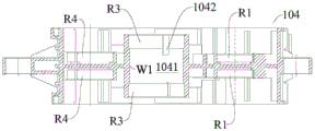
对于设置锁止装置200的动力总成1000,其壳体103及变速器102的结构如图7-图10所示,其中如图13所示,且中间壳体104限定出容纳腔1041,锁止装置200设置在该容纳腔1041内,两个第三安装孔R3连通,且共同限定出该容纳腔1041,该第三安装孔R3的内壁面W1需要机加工处理。如图14 所示,与第三安装孔R3对应的第二中间轴Ⅲ的另一端通过轴承B1支承在第三安装孔R3内,第二中间轴Ⅲ的另一端穿过轴承B1并超出轴承B1,且超出的部分设有锁止装置连接部C,锁止装置连接部C用于与锁止装置200相连。在一个具体的实施例中,锁止装置连接部C用于与锁止装置200通过花键结构相连。For the
下面简单描述根据本发明的动力传动系统10000的一些实施例,在这些实施例中,动力传动系统10000包括锁止装置200和至少一个动力总成1000。Some embodiments of a
动力总成1000包括第一动力组件100a和第二动力组件100b,第一动力组件100a与第二动力组件 100b在左右方向上对称设置,第一动力组件100a用于驱动左侧的车轮,第二动力组件100b用于驱动右侧的车轮,第一动力组件100a和第二动力组件100b均包括壳体103和设在壳体103内的电机101和变速器102,变速器102适于连接在电机101与对应侧的车轮之间。The
如图12-图15所示,两个壳体103相连设置且两个壳体103的连接部分限定出容纳腔1041,锁止装置200设在容纳腔1041内,其中第一动力组件100a和第二动力组件100b通过锁止装置200相连以可选择性同步。As shown in FIGS. 12-15 , the two
由此动力总成1000具有两种工作状态,即解锁状态和锁止状态,动力总成1000处于锁止状态时,第一动力组件100a与第二动力组件100b通过锁止装置200同步,从而使第一动力组件100a驱动的车轮与第二动力组件100b驱动的车轮同步转动;动力总成1000处于解锁状态时,第一动力组件100a与第二动力组件100b相互独立。Therefore, the
当一侧车轮打滑时,锁止装置200同步第一动力组件100a和第二动力组件100b,从而将未打滑的车轮的对应的动力组件的动力通过锁止装置200输出给打滑侧的车轮,实现动力驱动,有助于车辆脱困。When the wheel on one side slips, the
当一侧的动力组件损坏或故障时,锁止装置200同步第一动力组件100a和第二动力组件100b,从而将正常工作的动力组件的动力通过锁止装置200输出给另一侧的动力组件以驱动该侧的车轮,实现动力驱动,使用更加方便。When the power assembly on one side is damaged or faulty, the
根据本发明实施例的动力传动系统10000,通过设置锁止装置200,可以发挥动力传动系统10000 的最大动力传输优势,整车动力性增强,有助于打滑时脱困,且在其中一侧的动力组件损坏时,仍能正常驱动车辆。According to the
动力传动系统10000具有两个动力总成1000,且两个动力总成1000分别驱动车辆的前轮和车辆的后轮。The
在一些实施例中,锁止装置200可以为一个,这样两个动力总成1000中的一个的第一动力组件100a 和第二动力组件100b通过锁止装置200相连以可选择性同步。这样,前驱动力总成1000和后驱动力总成1000中,设置了锁止装置200的动力总成1000,动力性能好,脱困能力强。In some embodiments, the
在另一些实施例中,锁止装置200可以为两个,每个动力总成1000的第一动力组件100a和第二动力组件100b均通过一个锁止装置200相连以可选择性同步。这样前驱动力总成1000和后驱动力总成 1000均动力性能好,脱困能力强。In other embodiments, there may be two locking
在该实施例中,锁止装置200设置在两个变速器102之间,从而两个变速器102通过锁止装置200 相连以可选择性同步。In this embodiment, the lock-up
在变速器102为三级减速器的实施例中,两个第二中间轴Ⅲ通过锁止装置200相连以可选择性同步,将锁止装置200布置在两个第二中间轴Ⅲ之间,锁止装置200需要同步的两个轴的转速适中,且锁止装置200与三级减速器的齿轮不干涉,同时占用空间小,动力总成1000的内部的布局会更合理。In the embodiment in which the
如图13和图15所示,第一动力组件100a的第二子变速器102壳体103与第二动力组件100b的第二子变速器102壳体103相连且共同限定出容纳腔1041,锁止装置200设置在容纳腔1041内,更加具体地,两个第二子变速器102壳体103一体形成中间壳体104,中间壳体104上设有两个与三级减速器的第二中间轴Ⅲ一一对应的两个第三安装孔R3,两个第三安装孔R3相互连通且共同限定出容纳腔1041。As shown in FIG. 13 and FIG. 15 , the
下面参照图16-图19描述根据本发明的锁止装置200。如图16-图19所示的锁止装置200为单向锁止装置200a。如图16-图19所示,锁止装置200包括第一法兰201a、第二法兰201b、同步环202 和驱动组件203。The
第一法兰201a适于固定在第一轴X1上,第二法兰201b适于固定在第二轴X2上,同步环202与第一法兰201a常相连以适于随第一法兰201a同步转动,即同步环202与第一法兰201a一直处于连接状态,且第一法兰201a转动时,同步环202随第一法兰201a转动,同步环202可相对第一法兰201a滑动,同步环202相对第一法兰201a沿第一法兰201a的轴向可滑动。The
驱动组件203可选择性推动同步环202沿第一法兰201a的轴向从解锁位置滑动至锁止位置,同步环202位于锁止位置时,同步环202与第二法兰201b相连以适于使第二法兰201b随第一法兰201a同步转动,同步环202位于解锁位置时,同步环202与第二法兰201b分离。The
也就是说,同步环202在驱动组件203的推动下相对第一法兰201a沿第一法兰201a的轴向移动,当同步环202位于锁止位置时,同步环202与第一法兰201a相连,且同步环202还与第二法兰201b相连,从而第一法兰201a通过同步环202带动第二法兰201b同步转动,实现动力的传递;同步环202位于解锁位置时,同步环202与第一法兰201a相连,且同步环202与第二法兰201b分离,从而第一法兰 201a和第二法兰201b均独立转动。That is to say, the synchronizing
根据本发明实施例的锁止装置200,可以实现单向锁止,从而结构简单,占用空间少,好布置,同时故障率低,锁止后,能发挥传动系统的最大动力传输优势,整车动力性增强,车轮打滑时,利于脱困。According to the
在本发明的一个实施例中,驱动组件203包括电磁铁2031、顶针2032和驱动件2033。电磁铁2031适于固定在壳体103上,如图13所示,壳体103上设有卡接结构1042,电磁铁2031通过卡接结构1042与壳体103相连,具体地,电磁铁2031卡接在中间壳体104上。In one embodiment of the present invention, the driving
顶针2032的一端与第一法兰201a可滑动地相连,第一法兰201a上设有通孔D,顶针2032可滑动地设在通孔D内。One end of the
驱动件2033上设有驱动型面S,顶针2032的另一端与驱动型面S配合,具体地,顶针2032的另一端的端面一直止抵驱动型面S。The driving
电磁铁2031可选择性通电,电磁铁2031通电时,驱动件2033被固定,由于第一法兰201a的转动,驱动件2033通过驱动型面S驱动顶针2032沿第一法兰201a的轴向移动,并推动同步环202从解锁位置滑动至锁止位置。The
可选地,顶针2032与驱动型面S均为多个且一一对应,且多个顶针2032沿第一法兰201a的周向间隔设置。在本发明的一些具体的实例中,顶针2032和驱动型面S均为三个。Optionally, both the ejector pins 2032 and the driving profile S are in a plurality and one-to-one correspondence, and the plurality of
可选地,驱动型面S为V型型面,造型简单,制造容易。如图16所示,在第一法兰201a的轴向上, V型型面的开口从远离第二法兰201b的一端向靠近第二法兰201b的一端增大。Optionally, the driving profile S is a V profile, which is simple in shape and easy to manufacture. As shown in FIG. 16, in the axial direction of the
进一步地,在第一法兰201a的轴向上,V型型面的侧壁从远离第二法兰201b的一端向靠近第二法兰201b的一端沿直线或弧线延伸。Further, in the axial direction of the
锁止装置200还可以包括衬套204,衬套204套设固定在第一法兰201a上,且在第一法兰201a的轴向上,电磁铁2031夹设在衬套204与壳体103之间,由此电磁铁2031的固定更牢固,锁止装置200 的可靠性更高。The
锁止装置200还可以包括弹性复位件205,弹性复位件205与第二法兰201b相连,且在第一法兰 201a的轴向上位于同步环202与第二法兰201b之间,同步环202从解锁位置向锁止位置移动过程中,弹性复位件205被压缩。电磁铁2031断电时,弹性复位件205推动同步环202从锁止位置滑动至解锁位置。The
优选地,弹性复位件205为波形弹簧,由此弹性复位件205与第二法兰201b的接触面积大,且弹性复位件205与同步环202的接触面积大,对同步环202的受力更均匀。Preferably, the
第一法兰201a包括固定套筒、安装套筒和导向套筒,固定套筒套设固定在第一轴X1上,电磁铁2031 和驱动件2033均套设在固定套筒外,安装套筒上设有沿第一法兰201a的轴向贯穿安装套筒的通孔D,顶针2032可滑动地设在通孔D内,导向套筒设有导向槽,顶针2032可滑动地设在导向槽内,导向槽以及通孔D均可以使确保了顶针2032的运动轨迹。The
在第一法兰201a的轴向上,固定套筒、安装套筒和导向套筒依次相连且与第二法兰201b的距离递减。In the axial direction of the
如图16-图19所示的实施例中,在第一法兰201a的径向上,固定套筒、安装套筒和导向套筒从内向外依次设置,即在第一法兰201a的径向上,固定套筒、安装套筒和导向套筒与第一轴X1的距离依次减小。In the embodiment shown in FIGS. 16-19 , in the radial direction of the
如图16和图17所示,同步环202的外周面设有外齿圈部2021,导向套筒的内周面上设有与外齿圈部2021的齿配合的内齿槽20132a,通过内齿槽20132a与外齿圈部2021的配合,使同步环202与第一法兰201a常相连。同步环202的内周面设有内齿圈部2022,第二法兰201b的外周面上设有适于与内齿圈部2022的齿配合的外齿槽20132b,当同步环202位于锁止位置时,外齿槽20132b与内齿圈部2022 配合,从而同步环202带动第二法兰201b同步转动。As shown in FIG. 16 and FIG. 17 , the outer peripheral surface of the synchronizing
当然,单向锁止装置200a的实现形式并不限于此,下面简单描述单向锁止装置200a的另一个实施例,该单向锁止装置200a包括第一法兰201a、第二法兰201b、同步环202和驱动组件203。该实施例中的第一法兰201a以及驱动组件203可以参照图25-图29中的第二法兰201b以及第二驱动组件203b。同步环202的内周面设有内齿圈部2022,导向套筒的外周面上设有与内齿圈部2022的齿配合的外齿槽 20132b,同步环202的外周面设有外齿圈部2021,第一法兰201a的内周面上设有适于与外齿圈部2021 的齿配合的内齿槽20132a。也就是说,本实施例的单向锁止装置200a中,同步环202与第一法兰201a 是内啮合,图16-图19所示的单向锁止装置200a的实施例中,同步环202与第一法兰201a是外啮合。Of course, the implementation form of the one-
下面参照图16-图19并结合图2描述根据本发明实施例的单向锁止装置200a的工作过程:The working process of the one-
1)电磁铁2031不通电时1) When the
当左右车轮没打滑或两边电机101都能正常工作时,电磁铁2031不通电。第一法兰201a、顶针2032、驱动件2033、同步环202随第一轴X1转动,第二法兰201b随第二轴X2同步转动,弹性复位件205将同步环202与第二法兰201b顶开。When the left and right wheels do not slip or the
2)电磁铁2031通电时2) When the
当检测到有一侧车轮打滑或者一侧电机出现故障的信号,手动或者自动控制电磁铁2031通电。电磁铁2031产生电磁吸力将驱动件2033固定住,而第一法兰201a和顶针2032仍然随第一轴X1转动,促使被固定的驱动件2033通过驱动型面S将顶针2032沿驱动型面S顶向第二法兰201b,从而同步环 202被顶针2032的轴向力推动,与第二法兰201b结合,最终第一轴X1与第二轴X2锁止并同步转动。When it is detected that one side of the wheel is slipping or one side of the motor is faulty, the
3)同步环202从锁止位置向解锁位置移动时,只需将电磁铁2031断电,同步环202在弹性复位件 205的弹力作用下被推回初始位置。3) When the synchronizing
由此,单向锁止装置200a通过电磁力驱动,控制简单,占用空间小且承载能力大。Therefore, the one-
下面描述具有上述单向锁止装置200a的动力总成1000,动力总成1000包括上述锁止装置200、第一动力组件100a和第二动力组件100b,第一动力组件100a用于驱动左侧的车轮,第二动力组件100b 用于驱动右侧的车轮,第一动力组件100a和第二动力组件100b均包括电机101和变速器102,变速器 102适于连接在电机101与对应侧的车轮之间,第一动力组件100a包括第一轴X1,第二动力组件100b 包括第二轴X2,第一法兰201a固定在第一轴X1上,第二法兰201b固定在第二轴X2上,锁止装置200 用于可选择性同步第一轴X1与第二轴X2。The following describes the
可选地,变速器102为三级减速器,如图2和图3所示,三级减速器包括输入轴Ⅰ、第一中间轴Ⅱ、第二中间轴Ⅲ和输出轴Ⅳ,其中第一动力组件100a的输入轴Ⅰ、第一中间轴Ⅱ、第二中间轴Ⅲ和输出轴Ⅳ中的一个为第一轴X1,第二动力组件100b的输入轴Ⅰ、第一中间轴Ⅱ、第二中间轴Ⅲ和输出轴Ⅳ中的一个为第二轴X2。Optionally, the
可以理解的是,为了使第一动力组件100a与第二动力组件100b同步,第一轴X1和第二轴X2同为输入轴Ⅰ、输出轴Ⅳ、第一中间轴Ⅱ或第二中间轴Ⅲ。It can be understood that, in order to synchronize the
优选地,锁止装置200连接在两个第二中间轴Ⅲ之间以可选择性同步两个第二中间轴Ⅲ。Preferably, the
下面参照图25-图29描述根据本发明的锁止装置200。如图25-图29所示的锁止装置200为双向锁止装置200b。The
如图25-图29所示,锁止装置200包括第一法兰201a、第二法兰201b、第一法兰锁止结构Q1和第二法兰锁止结构Q2。As shown in FIGS. 25-29 , the
第一法兰201a适于固定在第一轴X1上,第二法兰201b适于固定在第二轴X2上。The
第一法兰锁止结构Q1用于可选择性锁止第一法兰201a与第二法兰201b,以适The first flange locking structure Q1 is used to selectively lock the
于使第二法兰201b随第一法兰201a同步转动。In order to make the
第二法兰锁止结构Q2用于可选择性锁止第二法兰201b与第一法兰201a,以适于使第一法兰201a 随第二法兰201b同步转动。The second flange locking structure Q2 is used to selectively lock the
如图25-图29所示,第一法兰锁止结构Q1包括第一同步环202a和第一驱动组件203a,第二法兰锁止结构Q2包括第二同步环202b和第二驱动组件203b。As shown in FIGS. 25-29 , the first flange locking structure Q1 includes a
第一同步环202a与第一法兰201a常相连以适于随第一法兰201a同步转动,且第一同步环202a可相对第一法兰201a滑动,第一驱动组件203a可选择性推动第一同步环202a沿第一法兰201a的轴向从第一解锁位置滑动至第一锁止位置,第一同步环202a位于第一锁止位置时,第一同步环202a与第二同步环202b相连以适于使第二法兰201b随第一法兰201a同步转动,第一同步环202a位于解锁位置时,第一同步环202a与第二同步环202b分离。The
第二同步环202b与第二法兰201b常相连以适于随第二法兰201b同步转动,且第二同步环202b可相对第二法兰201b滑动,第二驱动组件203b可选择性推动第二同步环202b沿第二法兰201b的轴向从第二解锁位置滑动至第二锁止位置,第二同步环202b位于第二锁止位置时,第二同步环202b与第一同步环202a相连以适于使第一法兰201a随第二法兰201b同步转动,第二同步环202b位于解锁位置时,第一同步环202a与第二同步环202b分离。The
也就是说,第一同步环202a在第一驱动组件203a的推动下相对第一法兰201a沿第一法兰201a的轴向移动,当第一同步环202a位于第一锁止位置时,第一同步环202a与第一法兰201a相连,且第一同步环202a还与第二同步环202b相连,从而第一法兰201a通过第一同步环202a和第二同步环202b 的配合带动第二法兰201b同步转动,实现动力的传递;第一同步环202a位于解锁位置时,第一同步环 202a与第一法兰201a相连,且第一同步环202a与第二同步环202b分离,从而第一法兰201a和第二法兰201b均独立转动。That is to say, the
第二同步环202b在第二驱动组件203b的推动下相对第二法兰201b沿第二法兰201b的轴向移动,当第二同步环202b位于第二锁止位置时,第二同步环202b与第二法兰201b相连,且第二同步环202b 还与第一同步环202a相连,从而第二法兰201b通过第一同步环202a和第二同步环202b的配合带动第一法兰201a同步转动,实现动力的传递;第二同步环202b位于解锁位置时,第二同步环202b与第二法兰201b相连,且第二同步环202b与第一同步环202a分离,从而第一法兰201a和第二法兰201b均独立转动。The
根据本发明实施例的锁止装置200,可以实现双向锁止,从而实现动力从第一法兰201a传递至第二法兰201b,或者动力从第二法兰201b传递至第一法兰201a,控制简单,占用空间小,好布置,且承载能力大,锁止后,能发挥传动系统的最大动力传输优势,整车动力性增强,车轮打滑时,利于脱困。According to the
如图25-图29所示,第一驱动组件203a包括第一电磁铁2031a、第一顶针2032a、第一驱动件2033a。第一电磁铁2031a适于固定在壳体103上,第一顶针2032a的一端与第一法兰201a可滑动地相连,第一驱动件2033a上设有第一驱动型面S1,第一顶针2032a的另一端与第一驱动型面S1配合,第一电磁铁2031a可选择性通电,第一电磁铁2031a通电时,第一驱动件2033a被固定,第一法兰201a转动,从而第一驱动件2033a通过第一驱动型面S1驱动第一顶针2032a沿第一法兰201a的轴向移动,并且第一顶针2032a推动第一同步环202a从第一同步环202a与第二同步环202b分离的位置移动至第一同步环202a与第二同步环202b相连的位置。As shown in FIGS. 25-29 , the first driving assembly 203a includes a
如图25-图29所示,第二驱动组件203b包括第二电磁铁2031b、第二顶针2032b、第二驱动件2033b。第二电磁铁2031b适于固定在壳体103上,第二顶针2032b的一端与第二法兰201b可滑动地相连,第二驱动件2033b上设有第二驱动型面S1,第二顶针2032b的另一端与第二驱动型面S1配合,第二电磁铁2031b可选择性通电,第二电磁铁2031b通电时,第二驱动件2033b被固定,第二法兰201b转动,从而第二驱动件2033b通过第二驱动型面S1驱动第二顶针2032b沿第二法兰201b的轴向移动,并且第二顶针2032b推动第二同步环202b从第一同步环202a与第二同步环202b分离的位置移动至第一同步环202a与第二同步环202b相连的位置。As shown in FIGS. 25-29 , the second driving assembly 203b includes a
如图25-图29所示,第一顶针2032a与第一驱动型面S1均为多个且一一对应,第一顶针2032a沿第一法兰201a的周向间隔设置,第二顶针2032b与第二驱动型面S1均为多个且一一对应,第二顶针 2032b沿第二法兰201b的周向间隔设置。As shown in FIGS. 25-29 , the
第一驱动型面S1为V型型面,在第一法兰201a的轴向上,第一驱动件2033a的V型型面的开口从远离第二法兰201b的一端向靠近第二法兰201b的一端增大。在第一法兰201a的轴向上,第一驱动件2033a的V型型面的侧壁从远离第二法兰201b的一端向靠近第二法兰201b的一端沿直线或弧线延伸。The first driving surface S1 is a V-shaped surface. In the axial direction of the
第二驱动型面S1为V型型面,在第二法兰201b的轴向上,第二驱动件2033b的V型型面的开口从远离第一法兰201a的一端向靠近第一法兰201a的一端增大。在第二法兰201b的轴向上,第二驱动件 2033b的V型型面的侧壁从远离第一法兰201a的一端向靠近第一法兰201a的一端沿直线或弧线延伸。The second driving profile S1 is a V profile. In the axial direction of the
进一步地,第一法兰锁止结构Q1还包括第一衬套204a,第一衬套204a套设固定在第一法兰201a 上,且在第一法兰201a的轴向上,第一电磁铁2031a夹设在第一衬套204a与对应的壳体103之间。Further, the first flange locking structure Q1 further includes a
第二法兰锁止结构Q2还包括第二衬套204b,第二衬套204b套设固定在第二法兰201b上,且在第二法兰201b的轴向上,第二电磁铁2031b夹设在第二衬套204b与对应的壳体103之间。The second flange locking structure Q2 further includes a second bushing 204b, the second bushing 204b is sleeved and fixed on the
第一法兰锁止结构Q1还包括第一止挡片206a和第一弹性复位件205a,第一弹性复位件205a与第一止挡片206a相连,第一止挡片206a与第一法兰201a相连,在第一法兰201a的轴向上,第一弹性复位件205a位于第一同步环202a与第一止挡片206a之间,第一同步环202a从第一解锁位置向第一锁止位置移动过程中,第一弹性件复位件被压缩。The first flange locking structure Q1 further includes a
可选地,第一止挡片206a与第一法兰201a通过第一螺纹连接件207a连接。Optionally, the
第二法兰锁止结构Q2还包括第二止挡片206b和第二弹性复位件205b,第二弹性复位件205b与第二止挡片206b相连,第二止挡片206b与第二法兰201b相连,在第二法兰201b的轴向上,第二弹性复位件205b位于第二同步环202b与第二止挡片206b之间,第二同步环202b从第二解锁位置向第二锁止位置移动过程中,第二弹性件复位件被压缩。The second flange locking structure Q2 further includes a second stop piece 206b and a second
可选地,第二止挡片206b与第二法兰201b通过第二螺纹连接件207b连接。Optionally, the second blocking piece 206b is connected with the
可选地,第一弹性复位件205a和第二弹性复位件205b可以均为波形弹簧。Optionally, both the first elastic restoring
在本发明的一些实施例中,如图25-图29所示,第一法兰201a包括第一固定套筒2011a、第一安装套筒2012a和第一导向套筒2013a,第一固定套筒2011a套设固定第一轴X1上,第一电磁铁2031a 和第一驱动件2033a均套设在第一固定套筒2011a外,第一安装套筒2012a上设有沿第一法兰201a的轴向贯穿第一安装套筒2012a的第一通孔DD1,第一顶针2032a可滑动地设在第一通孔DD1内,第一导向套筒2013a上设有第一导向槽20131a,第一顶针2032a可滑动地设在第一导向槽20131a内。In some embodiments of the present invention, as shown in FIGS. 25-29 , the
在第一法兰201a的轴向上,第一固定套筒2011a、第一安装套筒2012a和第一导向套筒2013a依次相连且与第二法兰201b的距离递减。In the axial direction of the
在本发明的一些实施例中,如图25-图29所示,第二法兰201b包括第二固定套筒2011b、第二安装套筒2012b和第二导向套筒2013b,第二固定套筒2011b套设固定第二轴X2上,第二电磁铁2031b 和第二驱动件2033b均套设在第二固定套筒2011b外,第二安装套筒2012b上设有沿第二法兰201b的轴向贯穿第二安装套筒2012b的第二通孔D2,第二顶针2032b可滑动地设在第二通孔D2内,第二导向套筒2013b上设有第二导向槽,第二顶针2032b可滑动地设在第二导向槽内。In some embodiments of the present invention, as shown in FIGS. 25-29 , the
在第二法兰201b的轴向上,第二固定套筒2011b、第二安装套筒2012b和第二导向套筒2013b依次相连且与第一法兰201a的距离递减。In the axial direction of the
在如图25-图29所示的具体的实施例中,第一法兰201a的第一导向槽20131a设在第一导向套筒 2013a的内周面上,第二法兰201b的第二导向槽设在第二导向套筒2013b的外周面上。In the specific embodiment shown in FIGS. 25-29 , the
进一步地,第一同步环202a的外周面设有第一外齿圈部2021a,第一导向套筒2013a的内周面上设有与所述第一外齿圈部2021a的齿配合的内齿槽20132a,第二同步环202b的内周面设有第二内齿圈部 2022b,第二导向套筒2013b的外周面上设有与第二内齿圈部2022b的齿配合的外齿槽20132b。第一同步环202a的内周面设有第一内齿圈部2022a,第二同步环202b的外周面上设有适于与第一内齿圈部 2022a的齿配合的齿槽。第一中间连接部2023a连接在第一外齿圈部2021a与第一内齿圈部2022a之间。第二中间连接部2023b连接在第二外齿圈部2021b与第二内齿圈部2022b之间,第二外齿圈部2021b适于与第一内齿圈部2022a配合。Further, the outer peripheral surface of the
如图25-图29所示,在径向上,第一导向套筒2013a、第一同步环202a、第二同步环202b和第二导向套筒2013b从外向内依次设置。As shown in FIGS. 25-29 , in the radial direction, the
通过上述描述可知,如图25-图29所示,锁止装置200包括第一法兰201a、第二法兰201b、第一法兰锁止结构Q1和第二法兰锁止结构Q2。第一法兰锁止结构Q1用于可选择性锁止第一法兰201a与第二法兰201b,以适于使第二法兰201b随第一法兰201a同步转动;第二法兰锁止结构Q2用于可选择性锁止第二法兰201b与第一法兰201a,以适于使第一法兰201a随第二法兰201b同步转动。From the above description, as shown in FIGS. 25-29 , the
第一法兰锁止结构Q1和第二法兰锁止结构Q2均包括同步环202和驱动组件203。同步环202与对应的法兰常相连以适于随该对应的法兰同步转动,且同步环202可相对该对应的法兰滑动,驱动组件203 可选择性推动同步环202沿对应的法兰的轴向从解锁位置滑动至锁止位置,同步环202位于锁止位置时,两个同步环202相连以适于使另一法兰随与该同步环202对应的法兰同步转动,同步环202位于解锁位置时,两个同步环202分离。Both the first flange locking structure Q1 and the second flange locking structure Q2 include a synchronizing
每个驱动组件203均包括电磁铁2031、顶针2032和驱动件2033,电磁铁2031适于固定在壳体103 上,顶针2032的一端与对应的法兰可滑动地相连,驱动件2033上设有驱动型面S,顶针2032的另一端与驱动型面S配合,电磁铁2031可选择性通电,电磁铁2031通电时,驱动件2033被固定以通过驱动型面S驱动顶针2032沿对应的法兰的轴向移动,并推动对应的同步环202从两个同步环202分离的位置移动至两个同步环202相连的位置。Each driving
可选地,顶针2032与驱动型面S均为多个且一一对应,顶针2032沿对应的法兰的周向间隔设置。Optionally, both the ejector pins 2032 and the driving profile S are in multiple and one-to-one correspondence, and the ejector pins 2032 are arranged at intervals along the circumferential direction of the corresponding flange.
可选地,驱动型面S为V型型面,在对应的法兰的轴向上,V型型面的开口从远离另一法兰的一端向靠近另一法兰的一端增大。Optionally, the driving profile S is a V-profile, and in the axial direction of the corresponding flange, the opening of the V-profile increases from an end away from the other flange to an end close to the other flange.
可选地,在对应的法兰的轴向上,V型型面的侧壁从远离另一法兰的一端向靠近另一法兰的一端沿直线或弧线延伸。Optionally, in the axial direction of the corresponding flange, the side wall of the V-shaped surface extends along a straight line or an arc from an end away from the other flange to an end close to the other flange.
可选地,第一法兰锁止结构Q1和第二法兰锁止结构Q2均还包括衬套204,衬套204套设固定在对应的法兰上,且在对应的法兰的轴向上,电磁铁2031夹设在衬套204与对应的壳体103之间。Optionally, both the first flange locking structure Q1 and the second flange locking structure Q2 further include
可选地,第一法兰锁止结构Q1和第二法兰锁止结构Q2均还包括:止挡片和弹性复位件205,弹性复位件205与止挡片相连,止挡片与对应的法兰相连,在对应的法兰的轴向上,弹性复位件205位于对应的同步环202与所止挡片之间,对应的同步环202从解锁位置向锁止位置移动过程中,弹性件复位件被压缩。Optionally, both the first flange locking structure Q1 and the second flange locking structure Q2 further include: a stop piece and an
可选地,弹性复位件205为波形弹簧。Optionally, the elastic restoring
可选地,第一法兰201a和第二法兰201b均可以包括固定套筒、安装套筒和导向套筒。固定套筒套设固定在对应的轴上,电磁铁2031和驱动件2033均套设在固定套筒外,安装套筒上设有沿对应的法兰的轴向贯穿安装套筒的通孔D,顶针2032可滑动地设在通孔D内,导向套筒上设有导向槽,顶针2032 可滑动地设在导向槽内。Optionally, both the
其中,在对应的法兰的轴向上,固定套筒、安装套筒和导向套筒依次相连且与另一法兰的距离递减。第一法兰201a的导向槽设在导向套筒的内周面上,第二法兰201b的导向槽设在导向套筒的外周面上。Wherein, in the axial direction of the corresponding flange, the fixed sleeve, the installation sleeve and the guide sleeve are connected in sequence and the distance from the other flange decreases. The guide groove of the
第一法兰锁止结构Q1的同步环202的外周面设有外齿圈部2021,第一法兰锁止结构Q1的导向套筒的内周面上设有与外齿圈部2021的齿配合的内齿槽20132a;第二法兰锁止结构Q2的同步环202的内周面设有内齿圈部2022,第二法兰锁止结构Q2的导向套筒的外周面上设有与内齿圈部2022的齿配合的外齿槽20132b。The outer peripheral surface of the synchronizing
下面参照图25-图29并结合图2描述根据本发明实施例的双向锁止装置200b的工作过程:The working process of the
1)第一电磁铁2031a和第二电磁铁2031b均不通电时1) When neither the
当左右车轮没打滑或两边电机101都能正常工作时,第一电磁铁2031a和第二电磁铁2031b均不通电。第一法兰201a、第一顶针2032a、第一驱动件2033a、第一同步环202a随第一轴X1转动,第二法兰201b、第二顶针2032b、第二驱动件2033b、第二同步环202b随第二轴X2同步转动,第一弹性复位件205a将第一同步环202a与第二同步环202b顶开,第二弹性复位件205b将第一同步环202a与第二同步环202b顶开。When the left and right wheels do not slip or the
2)第一电磁铁2031a通电时2) When the
当检测到有右侧车轮打滑的信号,或者右侧的电机出现故障时,手动或者自动控制第一电磁铁2031a 通电。第一电磁铁2031a产生电磁吸力将第一驱动件2033a固定住,而第一法兰201a和第一顶针2032a 仍然随第一轴X1转动,促使被固定的第一驱动件2033a通过第一驱动型面S1将第一顶针2032a沿第一驱动型面S1顶向第二同步环202b,从而第一同步环202a被第一顶针2032a的轴向力推动,与第二同步环202b结合,最终第一轴X1与第二轴X2锁止并同步转动。When it is detected that there is a signal that the wheel on the right side is slipping, or the motor on the right side is faulty, the
4)第一同步环202a从第一锁止位置向第一解锁位置移动时,只需将第一电磁铁2031a断电,第一同步环202a在第一弹性复位件205a的弹力作用下被推回初始位置。4) When the
5)当检测到有左侧车轮打滑的信号或者左侧电机出现故障时,手动或者自动控制第二电磁铁2031b 通电。第二电磁铁2031b产生电磁吸力将第二驱动件2033b固定住,而第二法兰201b和第二顶针2032b 仍然随第二轴X2转动,促使被固定的第二驱动件2033b通过第二驱动型面S1将第二顶针2032b沿第二驱动型面S1顶向第一同步环202a,从而第二同步环202b被第二顶针2032b的轴向力推动,与第一同步环202a结合,最终第一轴X1与第二轴X2锁止并同步转动。5) When it is detected that the left wheel slips or the left motor fails, manually or automatically control the
6)第二同步环202b从第二锁止位置向第二解锁位置移动时,只需将第二电磁铁2031b断电,第二同步环202b在第二弹性复位件205b的弹力作用下被推回初始位置。6) When the
由此,双向锁止装置200b通过电磁力驱动,控制简单,占用空间小且承载能力大。Therefore, the two-
下面描述具有上述双向锁止装置200b的动力总成1000,动力总成1000包括上述锁止装置200、第一动力组件100a和第二动力组件100b,第一动力组件100a用于驱动左侧的车轮,第二动力组件100b 用于驱动右侧的车轮,第一动力组件100a和第二动力组件100b均包括电机101和变速器102,变速器 102适于连接在电机101与对应侧的车轮之间,第一动力组件100a包括第一轴X1,第二动力组件100b 包括第二轴X2,第一法兰201a固定在第一轴X1上,第二法兰201b固定在第二轴X2上,锁止装置200 用于可选择性同步第一轴X1与第二轴X2。The following describes a
可选地,变速器102为三级减速器,如图2和图3所示,三级减速器包括输入轴Ⅰ、第一中间轴Ⅱ、第二中间轴Ⅲ和输出轴Ⅳ,其中第一动力组件100a的输入轴Ⅰ、第一中间轴Ⅱ、第二中间轴Ⅲ和输出轴Ⅳ中的一个为第一轴X1,第二动力组件100b的输入轴Ⅰ、第一中间轴Ⅱ、第二中间轴Ⅲ和输出轴Ⅳ中的一个为第二轴X2。Optionally, the
可以理解的是,为了使第一动力组件100a与第二动力组件100b同步,第一轴X1和第二轴X2同为输入轴Ⅰ、输出轴Ⅳ、第一中间轴Ⅱ或第二中间轴Ⅲ。It can be understood that, in order to synchronize the
优选地,锁止装置200连接在两个第二中间轴Ⅲ之间以可选择性同步两个第二中间轴Ⅲ。Preferably, the
下面参照图20-图24,并结合图16-图19以及图25-图29,详细描述根据本发明的法兰组件 300。20-24, in conjunction with FIGS. 16-19 and 25-29, the
根据本发明实施例的法兰组件300包括法兰、同步环202和驱动组件203,同步环202与法兰常相连以适于随法兰同步转动,且同步环202可相对法兰滑动,驱动组件203可选择性驱动同步环202 沿法兰的轴向从解锁位置脱离。The
同步环202位于解锁位置时,同步环202与法兰的贴合端面M贴合,贴合端面M上设有向远离所述同步环202凹入的凹入部J。由此法兰的贴合端面M与同步环202的接触面积小,从而同步环202从解锁位置脱离时,阻力小,脱离更容易。When the synchronizing
具体而言,法兰组件300设置在箱体内,且法兰组件300浸在润滑油中,因此同步环202位于解锁位置时,同步环202与法兰的贴合端面M贴合,不易分离。而本发明通过,在贴合端面M上设置凹入部J,减少接触面积,从而使同步环202与法兰更容易脱开。Specifically, the
可选地,凹入部J包括设在贴合端面M上的环形凹槽,环形凹槽沿法兰的周向延伸一整圈。Optionally, the concave portion J includes an annular groove provided on the abutting end face M, and the annular groove extends for a full circle along the circumferential direction of the flange.
可选地,凹入部J可以包括设在贴合端面M上的多个凹坑,多个凹坑沿法兰的周向间隔设置。Optionally, the concave portion J may include a plurality of dimples provided on the fitting end surface M, and the plurality of dimples are arranged at intervals along the circumferential direction of the flange.
可选地,凹入部J可以包括设在贴合端面M上且沿法兰的轴向贯穿第一法兰201a的多个过孔,多个过孔沿法兰的周向间隔设置,过孔的设置不仅使同步环202更容易脱离法兰,还可以减轻法兰的重量。Optionally, the concave portion J may include a plurality of via holes provided on the fitting end face M and penetrating the
可以理解的是,这里的法兰可以是第一法兰201a,也可以是第二法兰201b。It can be understood that the flange here may be the
进一步地,在法兰套设在同步环202外的实施例中,同步环202包括在同步环202的径向上从外向内依次相连的外齿圈部2021、中间连接部2023和内齿圈部2022,法兰上设有与外齿圈部2021的齿配合的内齿槽20132a,在法兰的轴向上,凹入部J与至少部分内齿圈部2022相对设置,顶针2032与中间连接部2023相对设置,由此顶针2032的推力更容易传递到同步环202上。Further, in the embodiment in which the flange is sleeved outside the synchronizing
进一步地,在同步环202套设在法兰外的实施例中,同步环202包括在同步环202的径向上从外向内依次相连的外齿圈部2021、中间连接部2023和内齿圈部2022,法兰上设有与内齿圈部2022的齿配合的外齿槽20132b,在法兰的轴向上,凹入部J与至少部分外齿圈部2021相对设置。Further, in the embodiment in which the
下面简单描述包括根据本发明实施例的又一个锁止装置200。该锁止装置200为单向锁止装置 200a,包括上述实施例中的法兰组件300和第二法兰201b,法兰为第一法兰201a,第一法兰201a适于固定在第一轴X1上,第二法兰201b适于固定在第二轴X2上,驱动组件203可选择性推动同步环202 沿第一法兰201a的轴向从解锁位置滑动至锁止位置,同步环202位于锁止位置时,同步环202与第二法兰201b相连以适于使第二法兰201b随第一法兰201a同步转动,同步环202位于解锁位置时,同步环202与第二法兰201b分离。The following brief description includes yet another
该实施例与图16-图19所示的实施例的区别在于,设置顶针2032的法兰的结构不同,即在该实施例中设置顶针2032的法兰(第一法兰201a)与同步环202的贴合端面M上设有向远离同步环202的方向上凹入的凹入部J,由此同步环202与法兰的脱离更容易。具体地,电磁铁2031断电时,同步环202 与第一法兰201a更容易分离。The difference between this embodiment and the embodiment shown in FIGS. 16-19 is that the structure of the flange on which the
也就是说,上述法兰组件300可以用于单向锁止装置200a中。That is, the
下面简单描述包括根据本发明实施例的一个锁止装置200,该锁止装置200包括两组法兰组件 300。其中一组法兰组件300包括第一法兰201a、第一同步环202a和第一驱动组件203a;另一组法兰组件300包括第二法兰201b、第二同步环202b和第二驱动组件203b。The following brief description includes a
第一法兰201a适于固定在第一轴X1上,第二法兰201b适于固定在第二轴X2上,第一同步环202a 与第一法兰201a常相连以适于随第一法兰201a同步转动,且第一同步环202a可相对第一法兰201a滑动,第一驱动组件203a可选择性推动第一同步环202a沿第一法兰201a的轴向从第一解锁位置滑动至第一锁止位置,第一同步环202a位于第一锁止位置时,第一同步环202a与第二同步环202b相连以适于使第二法兰201b随第一法兰201a同步转动,第一同步环202a位于解锁位置时,第一同步环202a与第二同步环202b分离;The
第二同步环202b与第二法兰201b常相连以适于随第二法兰201b同步转动,且第二同步环202b可相对第二法兰201b滑动,第二驱动组件203b可选择性推动第二同步环202b沿第二法兰201b的轴向从第二解锁位置滑动至第二锁止位置,第二同步环202b位于第二锁止位置时,第二同步环202b与第一同步环202a相连以适于使第一法兰201a随第二法兰201b同步转动,第二同步环202b位于解锁位置时,第一同步环202a与第二同步环202b分离。The
也就是说,法兰组件300可以应用于双向锁止装置200b,从而第一法兰201a和第二法兰201b上均可以设置凹入部J,从而第一同步环202a与第一法兰201a更容易分离,第二法兰201b与第二同步环 202b更容易分离。具体地,第一电磁铁2031a断电时,第一同步环202a与第一法兰201a更容易分离;或者第二电磁铁2031b断电时,第二同步环202b与第二法兰201b更容易分离。That is, the
下面描述根据本发明实施例的动力传动系统10000,动力传动系统10000包括至少一个动力总成1000和锁止装置200。The following describes a
动力总成1000包括第一动力组件100a和第二动力组件100b,第一动力组件100a用于驱动左侧的车轮,第二动力组件100b用于驱动右侧的车轮,第一动力组件100a和第二动力组件100b均包括电机 101和变速器102,变速器102适于连接在电机101与对应侧的车轮之间;The
,其中第一动力组件100a和第二动力组件100b通过锁止装置200相连以可选择性同步,右侧的车轮和左侧的车轮中的一个打滑时或者两个电机101中的一个损坏或故障时,锁止装置200同步第一动力组件100a和第二动力组件100b。, wherein the
也就是说,锁止装置200用于在其中两侧车轮中的一侧车轮打滑或两个电机101中的一个损坏或者发生故障时,锁止第一动力组件100a和第二动力组件100b,使第一动力组件100a和第二动力组件100b 同步,从而使两侧的车轮同步转动,整车脱困能力强,一个电机101出现故障时,仍可以实现车辆的驱动。That is to say, the
该实施例的动力传动系统10000中,第一动力组件100a、第二动力组件100b以及壳体103均可以采用上述实施例中描述的第一动力组件100a、第二动力组件100b以及壳体103。当然,壳体103对应的是设置锁止装置200的壳体103。In the
锁止装置200可以是图16-图19所示的单向锁止装置200a,锁止装置200也可以是图25-图29所示的双向锁止装置200b,同时锁止装置200还可以是图20-图24所示的具有凹入部J的锁止装置200。The
具体而言,第一动力组件100a和第二动力组件100b均包括壳体103、电机101和变速器102均设在壳体103内,两个壳体103相连设置且两个壳体103的连接部分限定出容纳腔1041,锁止装置200 设在容纳腔1041内。两个变速器102通过锁止装置200相连以可选择性同步。变速器102为三级减速器。两个第二中间轴Ⅲ通过锁止装置200相连。当两个电机101中的一个损坏或出现故障,或者两侧车轮中的一侧车轮打滑时,两个第二中间轴Ⅲ同步转动。Specifically, the
锁止装置200包括两个法兰,两个法兰与两个轴一一对应地固定,用于可选择性锁止两个法兰,以适于使两个法兰同步转动的至少一个法兰锁止结构。The
法兰锁止结构包括同步环202和驱动组件203,同步环202与对应的法兰常相连以适于随该对应的法兰同步转动,且同步环202可相对该对应的法兰滑动;驱动组件203可选择性推动同步环202沿对应的法兰的轴向从解锁位置滑动至锁止位置,同步环202位于锁止位置时,两个法兰同步转动,同步环202 位于解锁位置时,两个法兰相互独立。The flange locking structure includes a synchronizing
进一步地,同步环202与对应的法兰的贴合端面M贴合,贴合端面M上设有向远离同步环202凹入的凹入部J。Further, the synchronizing
法兰包括固定套筒、安装套筒和导向套筒,固定套筒适于套设固定在轴上,电磁铁2031和驱动件 2033均套设在固定套筒外,安装套筒上设有沿法兰的轴向贯穿安装套筒的通孔D,顶针2032可滑动地设在通孔D内,导向套筒上设有导向槽,顶针2032可滑动地设在导向槽内,凹入部J设在安装套筒的端面上。The flange includes a fixed sleeve, an installation sleeve and a guide sleeve. The fixed sleeve is suitable for being sleeved and fixed on the shaft. The
可选地,法兰锁止结构为一个,法兰锁止结构用于可选择性锁止两个法兰,以适于使两个法兰中的一个随两个法兰中的另一个同步转动。这样锁止装置200为单向锁止装置200a。Optionally, the flange locking structure is one, and the flange locking structure is used to selectively lock the two flanges, so as to be suitable for synchronizing one of the two flanges with the other of the two flanges turn. In this way, the
可选地,法兰锁止结构为两个,法兰锁止结构用于可选择性锁止两个法兰;其中一个法兰锁止结构用于可选择性锁止两个法兰,以适于使两个法兰中的一个随两个法兰中的另一个同步转动;另一个法兰锁止结构用于可选择性锁止两个法兰,以适于使两个法兰中的另一个随两个法兰中的一个同步转动。由此锁止装置200为双向锁止装置200b。Optionally, there are two flange locking structures, and the flange locking structure is used to selectively lock the two flanges; one of the flange locking structures is used to selectively lock the two flanges, so as to It is suitable for making one of the two flanges rotate synchronously with the other of the two flanges; the other flange locking structure is used to selectively lock the two flanges, so as to be suitable for making the two flanges The other rotates synchronously with one of the two flanges. Thus, the
下面参照图1描述根据本发明实施例的一个动力传动系统10000。如图1所示,该动力传动系统10000包括第一动力总成1000、第二动力总成1000、第一锁止装置C1和第二锁止装置C2。A
第一动力总成1000用于驱动车辆的前车轮,第二动力总成1000用于驱动车辆的后车轮,第一动力总成1000和第二动力总成1000均包括第一动力组件100a和第二动力组件100b,第一动力组件100a 用于驱动左侧的车轮,第二动力组件100b用于驱动右侧的车轮,第一动力组件100a和第二动力组件100b 均包括电机101和变速器102,变速器102适于连接在电机101与对应侧的车轮之间。The
第一动力总成1000的第一动力组件100a和第二动力组件100b通过第一锁止结构相连以可选择性同步。The
第二动力总成1000的第一动力组件100a和第二动力组件100b通过第二锁止结构相连以可选择性同步。The
第一锁止装置C1和第二锁止装置C2均为双向锁止装置200b,双向锁止装置200b用于可选择性同步第一动力组件100a和第二动力组件100b,以使第一动力组件100a随第二动力组件100b同步运动或者使第二动力组件100b随第一动力组件100a同步运动。The first locking device C1 and the second locking device C2 are both two-
双向锁止装置200b包括第一法兰201a、第二法兰201b、第一法兰锁止结构Q1、第二法兰锁止结构 Q2。The
第一法兰201a固定在第一轴X1上,第一轴X1为第一动力组件100a的变速器102的传动轴,第二法兰201b固定在第二轴X2上,第二轴X2为第二动力组件100b的变速器102的传动轴。The
第一法兰锁止结构Q1用于可选择性锁止第一法兰201a与第二法兰201b,以适于使第二法兰201b 随第一法兰201a同步转动。The first flange locking structure Q1 is used to selectively lock the
第二法兰锁止结构Q2用于可选择性锁止第二法兰201b与第一法兰201a,以适于使第一法兰201a 随第二法兰201b同步转动。The second flange locking structure Q2 is used to selectively lock the
第一法兰锁止结构Q1和第二法兰锁止结构Q2均包括同步环202和驱动组件203。Both the first flange locking structure Q1 and the second flange locking structure Q2 include a synchronizing
同步环202与对应的法兰常相连以适于随该对应的法兰同步转动,且同步环202可相对该对应的法兰滑动,驱动组件203可选择性推动同步环202沿对应的法兰的轴向从解锁位置滑动至锁止位置。The synchronizing
同步环202位于锁止位置时,两个同步环202相连以适于使另一法兰随与该同步环202对应的法兰同步转动,同步环202位于解锁位置时,两个同步环202分离。When the synchronizing
驱动组件203包括:电磁铁2031、顶针2032和驱动件2033,电磁铁2031适于固定在壳体103上,顶针2032的一端与对应的法兰可滑动地相连,驱动件2033上设有驱动型面S,顶针2032的另一端与驱动型面S配合。The driving
电磁铁2031可选择性通电,对应侧的车轮打滑时,电磁铁2031通电,驱动件2033被固定以通过驱动型面S驱动顶针2032沿对应的法兰的轴向移动,并推动对应的同步环202从两个同步环202分离的位置移动至两个同步环202相连的位置。The
第一法兰锁止结构Q1和第二法兰锁止结构Q2均还包括止挡片和弹性复位件205,弹性复位件205 与止挡片相连,止挡片与对应的法兰相连,在对应的法兰的轴向上,弹性复位件205位于对应的同步环 202与所止挡片之间,对应的同步环202从解锁位置向锁止位置移动过程中,弹性件复位件被压缩。Both the first flange locking structure Q1 and the second flange locking structure Q2 also include a stopper piece and an
弹性复位件205为波形弹簧。The elastic restoring
动力传动系统10000具有单电机前驱模式,动力传动系统10000处于单电机前驱模式时,仅第一动力总成1000的一个电机101工作,第一锁止装置C1同步对应的第一动力组件100a和第二动力组件100b。The
动力传动系统10000具有单电机后驱模式,动力传动系统10000处于单电机后驱模式时,仅第二动力总成1000的一个电机101工作,第二锁止装置C2同步对应的第一动力组件100a和第二动力组件100b。The
动力传动系统10000具有第一双电机前驱模式,动力传动系统10000处于第一双电机前驱模式时,仅第一动力总成1000的两个电机101工作。The
动力传动系统10000具有第二双电机前驱模式,动力传动系统10000处于第二双电机前驱模式时,仅第一动力总成1000的两个电机101工作,且前车轮单侧打滑时,第一锁止装置C1同步对应的第一动力组件100a和第二动力组件100b。The
动力传动系统10000具有第一双电机后驱模式,动力传动系统10000处于第一双电机后驱模式时,仅第二动力总成1000的两个电机101工作。The
动力传动系统10000具有第二双电机后驱模式,动力传动系统10000处于第二双电机后驱模式时,仅第二动力总成1000的两个电机101工作,且后车轮单侧打滑时,第二锁止装置C2同步对应的第一动力组件100a和第二动力组件100b。The
动力传动系统10000具有双电机四驱模式,动力传动系统10000处于双电机四驱模式时,第一动力总成1000的两个电机101中仅一个工作,且第二动力总成1000的两个电机101中仅一个工作,第一锁止装置C1同步对应的第一动力组件100a和第二动力组件100b,且第二锁止装置C2同步对应的第一动力组件100a和第二动力组件100b。The
动力传动系统10000具有第一三电机四驱模式,动力传动系统10000处于第一三电机四驱模式时,第一动力总成1000的两个电机101中仅一个工作,且第二动力总成1000的两个电机101均工作,第一锁止装置C1同步对应的第一动力组件100a和第二动力组件100b。The
动力传动系统10000具有第二三电机四驱模式,动力传动系统10000处于第二三电机四驱模式时,第二动力总成1000的两个电机101中仅一个工作,且第一动力总成1000的两个电机101均工作,第二锁止装置C2同步对应的第一动力组件100a和第二动力组件100b。The
动力传动系统10000具有第一四电机四驱模式,动力传动系统10000处于第一四电机四驱模式时,第一动力总成1000的两个电机101工作,且第二动力总成1000的两个电机101工作。The
动力传动系统10000具有第二四电机四驱模式,动力传动系统10000处于第二四电机四驱模式时,第一动力总成1000的两个电机101工作,且第二动力总成1000的两个电机101工作,且前车轮单侧打滑时,第一锁止装置C1同步对应的第一动力组件100a和第二动力组件100b。The
动力传动系统10000具有第三四电机四驱模式,动力传动系统10000处于第三四电机四驱模式时,第一动力总成1000的两个电机101工作,且第二动力总成1000的两个电机101工作,且后车轮单侧打滑时,第二锁止装置C2同步对应的第一动力组件100a和第二动力组件100b。The
动力传动系统10000具有第四四电机四驱模式,动力传动系统10000处于第四四电机四驱模式时,第一动力总成1000的两个电机101工作,且第二动力总成1000的两个电机101工作,且前车轮单侧打滑且后车轮单侧打滑时,第一锁止装置C1同步对应的第一动力组件100a和第二动力组件100b,且第二锁止装置C2同步对应的第一动力组件100a和第二动力组件100b。The
根据本发明实施例的动力传动系统10000,前后动力总成1000均采用电驱动,且前后动力总成1000均采用双向锁止装置200b,该动力传动系统10000具有多种模式,更加适应车辆实际行驶过程中出现的各种工况,动力性好,且适应性好。According to the
本发明一些实施例的车辆,包括上述实施例的动力总成1000。Vehicles according to some embodiments of the present invention include the
本发明一些实施例的车辆,包括上述实施例的动力传动系统10000。Vehicles of some embodiments of the present invention include the
本发明一些实施例的车辆,包括上述实施例的锁止装置200。Vehicles according to some embodiments of the present invention include the
可以理解的是,本发明中上述动力总成1000、动力传动系统10000以及锁止装置200的多个实施例可以相互借鉴,例如,图25-图29中的双向锁止装置200b中的第二法兰201b,可以应用于单向锁止装置200a中。例如图20-图24中的法兰可以应用到双向锁止装置200b中,也可以应用到单向锁止装置200a中。例如,有些单向锁止装置200a中,采用了图25-图29中的双向锁止装置200b中的第二法兰201b,则与第二法兰201b可选择性同步的第一法兰201a的结构可以借鉴图16-图19中的第一法兰 201a的结构,但是在这个实施例中,第一法兰201a不会设置顶针2032。It can be understood that the above-mentioned embodiments of the
另外,在本发明中,法兰可以是第一法兰201a,法兰也可以是第二法兰201b,两个法兰可以包括第一法兰201a和第二法兰201b。In addition, in the present invention, the flange may be the
在本发明 的描述中,需要理解的是,术语“中心”、“纵向”、“横向”、“长度”、“宽度”、“厚度”、“上”、“下”、“前”、“后”、“左”、“右”、“竖直”、“水平”、“顶”、“底”“内”、“外”、“顺时针”、“逆时针”、“轴向”、“径向”、“周向”等指示的方位或位置关系为基于附图所示的方位或位置关系,仅是为了便于描述本发明和简化描述,而不是指示或暗示所指的装置或元件必须具有特定的方位、以特定的方位构造和操作,因此不能理解为对本发明的限制。In the description of the present invention, it should be understood that the terms "center", "longitudinal", "lateral", "length", "width", "thickness", "upper", "lower", "front", " Rear, Left, Right, Vertical, Horizontal, Top, Bottom, Inner, Outer, Clockwise, Counterclockwise, Axial, The orientation or positional relationship indicated by "radial direction", "circumferential direction", etc. is based on the orientation or positional relationship shown in the drawings, and is only for the convenience of describing the present invention and simplifying the description, rather than indicating or implying the indicated device or element It must have a specific orientation, be constructed and operate in a specific orientation, and therefore should not be construed as a limitation of the present invention.
此外,术语“第一”、“第二”仅用于描述目的,而不能理解为指示或暗示相对重要性或者隐含指明所指示的技术特征的数量。由此,限定有“第一”、“第二”的特征可以明示或者隐含地包括至少一个该特征。在本发明的描述中,“多个”的含义是至少两个,例如两个,三个等,除非另有明确具体的限定。In addition, the terms "first" and "second" are only used for descriptive purposes, and should not be construed as indicating or implying relative importance or implying the number of indicated technical features. Thus, a feature delimited with "first", "second" may expressly or implicitly include at least one of that feature. In the description of the present invention, "plurality" means at least two, such as two, three, etc., unless otherwise expressly and specifically defined.
在本发明中,除非另有明确的规定和限定,术语“安装”、“相连”、“连接”、“固定”等术语应做广义理解,例如,可以是固定连接,也可以是可拆卸连接,或成一体;可以是机械连接,也可以是电连接或彼此可通讯;可以是直接相连,也可以通过中间媒介间接相连,可以是两个元件内部的连通或两个元件的相互作用关系,除非另有明确的限定。对于本领域的普通技术人员而言,可以根据具体情况理解上述术语在本发明中的具体含义。In the present invention, unless otherwise expressly specified and limited, terms such as "installation", "connection", "connection", "fixation" and other terms should be understood in a broad sense, for example, it may be a fixed connection or a detachable connection , or integrated; it can be a mechanical connection or an electrical connection or can communicate with each other; it can be directly connected or indirectly connected through an intermediate medium, it can be the internal connection of two components or the interaction relationship between the two components, unless otherwise expressly qualified. For those of ordinary skill in the art, the specific meanings of the above terms in the present invention can be understood according to specific situations.
在本发明中,除非另有明确的规定和限定,第一特征在第二特征“上”或“下”可以是第一和第二特征直接接触,或第一和第二特征通过中间媒介间接接触。而且,第一特征在第二特征“之上”、“上方”和“上面”可是第一特征在第二特征正上方或斜上方,或仅仅表示第一特征水平高度高于第二特征。第一特征在第二特征“之下”、“下方”和“下面”可以是第一特征在第二特征正下方或斜下方,或仅仅表示第一特征水平高度小于第二特征。In the present invention, unless otherwise expressly specified and limited, a first feature "on" or "under" a second feature may be in direct contact between the first and second features, or the first and second features indirectly through an intermediary touch. Also, the first feature being "above", "over" and "above" the second feature may mean that the first feature is directly above or obliquely above the second feature, or simply means that the first feature is level higher than the second feature. The first feature being "below", "below" and "below" the second feature may mean that the first feature is directly below or obliquely below the second feature, or simply means that the first feature has a lower level than the second feature.
在本说明书的描述中,参考术语“一个实施例”、“一些实施例”、“示例”、“具体示例”、或“一些示例”等的描述意指结合该实施例或示例描述的具体特征、结构、材料或者特点包含于本发明的至少一个实施例或示例中。在本说明书中,对上述术语的示意性表述不必须针对的是相同的实施例或示例。而且,描述的具体特征、结构、材料或者特点可以在任一个或多个实施例或示例中以合适的方式结合。此外,在不相互矛盾的情况下,本领域的技术人员可以将本说明书中描述的不同实施例或示例以及不同实施例或示例的特征进行结合和组合。In the description of this specification, description with reference to the terms "one embodiment," "some embodiments," "example," "specific example," or "some examples", etc., mean specific features described in connection with the embodiment or example , structure, material or feature is included in at least one embodiment or example of the present invention. In this specification, schematic representations of the above terms are not necessarily directed to the same embodiment or example. Furthermore, the particular features, structures, materials or characteristics described may be combined in any suitable manner in any one or more embodiments or examples. Furthermore, those skilled in the art may combine and combine the different embodiments or examples described in this specification, as well as the features of the different embodiments or examples, without conflicting each other.
尽管上面已经示出和描述了本发明的实施例,可以理解的是,上述实施例是示例性的,不能理解为对本发明的限制,本领域的普通技术人员在本发明的范围内可以对上述实施例进行变化、修改、替换和变型。Although the embodiments of the present invention have been shown and described above, it should be understood that the above embodiments are exemplary and should not be construed as limiting the present invention. Embodiments are subject to variations, modifications, substitutions and variations.
Claims (26)
Priority Applications (4)
| Application Number | Priority Date | Filing Date | Title |
|---|---|---|---|
| CN201611265803.5A CN108263208B (en) | 2016-12-30 | 2016-12-30 | Locking device, power assembly, power transmission system and vehicle |
| EP17889344.2A EP3564546B1 (en) | 2016-12-30 | 2017-12-21 | Locking apparatus, powertrain, power transmission system, and vehicle |
| PCT/CN2017/117820 WO2018121419A1 (en) | 2016-12-30 | 2017-12-21 | Locking apparatus, powertrain, power transmission system, and vehicle |
| US16/475,005 US11359697B2 (en) | 2016-12-30 | 2017-12-21 | Locking device, power assembly, power transmission system, and vehicle |
Applications Claiming Priority (1)
| Application Number | Priority Date | Filing Date | Title |
|---|---|---|---|
| CN201611265803.5A CN108263208B (en) | 2016-12-30 | 2016-12-30 | Locking device, power assembly, power transmission system and vehicle |
Publications (2)
| Publication Number | Publication Date |
|---|---|
| CN108263208A CN108263208A (en) | 2018-07-10 |
| CN108263208B true CN108263208B (en) | 2020-01-03 |
Family
ID=62707890
Family Applications (1)
| Application Number | Title | Priority Date | Filing Date |
|---|---|---|---|
| CN201611265803.5A Active CN108263208B (en) | 2016-12-30 | 2016-12-30 | Locking device, power assembly, power transmission system and vehicle |
Country Status (4)
| Country | Link |
|---|---|
| US (1) | US11359697B2 (en) |
| EP (1) | EP3564546B1 (en) |
| CN (1) | CN108263208B (en) |
| WO (1) | WO2018121419A1 (en) |
Families Citing this family (7)
| Publication number | Priority date | Publication date | Assignee | Title |
|---|---|---|---|---|
| US11654761B2 (en) * | 2019-09-10 | 2023-05-23 | Dana Heavy Vehicle Systems Group, Llc | Electric propulsion system |
| CN111692314A (en) * | 2020-02-26 | 2020-09-22 | 吴有智 | One-way transmission shaft and one-way speed change mechanism |
| CN111623018A (en) * | 2020-04-29 | 2020-09-04 | 深圳亚太航空技术有限公司 | Two-way telescopic locking device |
| WO2022188159A1 (en) * | 2021-03-12 | 2022-09-15 | 浙江吉利控股集团有限公司 | Speed reducer structure with disengagement mechanism, and vehicle |
| CN115139772B (en) * | 2021-06-30 | 2023-05-05 | 比亚迪股份有限公司 | Electric drive assembly, four-wheel drive system and automobile |
| CN116141985A (en) * | 2023-02-27 | 2023-05-23 | 蜂巢传动系统(江苏)有限公司 | A driving system, method and vehicle |
| CN118928016A (en) * | 2024-08-26 | 2024-11-12 | 东风汽车集团股份有限公司 | Transmission components and distributed electric drive systems |
Citations (5)
| Publication number | Priority date | Publication date | Assignee | Title |
|---|---|---|---|---|
| CN103375506A (en) * | 2012-04-24 | 2013-10-30 | 福特全球技术公司 | Electromagnetically actuated clutch |
| CN103758889A (en) * | 2013-12-27 | 2014-04-30 | 精进电动科技(北京)有限公司 | Electromagnetic toothed clutch and double-motor hybrid system |
| CN103775602A (en) * | 2012-10-23 | 2014-05-07 | 福特全球技术公司 | Clutch mechanism |
| CN105090270A (en) * | 2014-05-14 | 2015-11-25 | 贺尔碧格传动技术控股有限公司 | Synchronous assembly |
| CN105317871A (en) * | 2014-06-05 | 2016-02-10 | 贺尔碧格传动技术控股有限公司 | Synchronizer ring for a synchronization unit of a manual transmission and method for manufacturing such synchronizer ring |
Family Cites Families (34)
| Publication number | Priority date | Publication date | Assignee | Title |
|---|---|---|---|---|
| US5078244A (en) | 1990-12-24 | 1992-01-07 | Eaton Corporation | Self-energizing synchronizer |
| US5497867A (en) | 1993-12-27 | 1996-03-12 | Eaton Corporation | Synchronizer with cone cup locater pins |
| JP2002206567A (en) * | 2001-01-12 | 2002-07-26 | Honda Motor Co Ltd | Electromagnetic clutch structure in driving force distribution device |
| US6948576B2 (en) | 2002-01-10 | 2005-09-27 | Jorge Angeles | Driving and transmission unit for use in rolling vehicles |
| JP2004112178A (en) | 2002-09-17 | 2004-04-08 | Fujitsu Quantum Devices Ltd | Transmission line and device having the same |
| US7513349B2 (en) * | 2005-11-30 | 2009-04-07 | Tm4 Inc. | Multi-position clutch |
| FR2902477B1 (en) | 2006-06-19 | 2008-08-01 | Renault Sas | ANTI-BLOCKING ROCKER SWITCH FOR LEVER SYNCHRONIZER |
| DE102006048737B3 (en) | 2006-10-12 | 2008-04-30 | Rheinmetall Landsysteme Gmbh | Drive for a tracked vehicle |
| CN201165197Y (en) | 2008-02-04 | 2008-12-17 | 重庆渝安创新科技(集团)有限公司 | Miniature car drive system |
| JP5117960B2 (en) * | 2008-08-22 | 2013-01-16 | アイシン・エィ・ダブリュ株式会社 | Vehicle drive device |
| CN201291750Y (en) | 2008-09-24 | 2009-08-19 | 比亚迪股份有限公司 | Pure-electric system |
| US7988584B2 (en) * | 2009-06-04 | 2011-08-02 | American Axle & Manufacturing, Inc. | Locking power transmitting device |
| US8265842B2 (en) * | 2009-07-23 | 2012-09-11 | Ford Global Technologies, Llc | Electronic locking differential |
| IT1400690B1 (en) * | 2010-04-15 | 2013-06-28 | Baruffaldi Spa | REVERSIBLE ELECTROMAGNETIC DEVICE, DOUBLE ACTION, FOR MOTORCYCLE TRANSMISSION TO / FROM A DUCT / CONDUCTOR ELEMENT |
| US8454471B2 (en) * | 2010-07-21 | 2013-06-04 | Ford Global Technologies, Llc | Electronic locking differential |
| DE102011080068A1 (en) | 2011-07-29 | 2013-01-31 | Zf Friedrichshafen Ag | Automated range-change transmission for drive train of motor vehicle, comprises countershaft-type main transmission, which has main shaft and countershaft, where rear-mounted group is drivingly connected downstream of main transmission |
| CN102673373A (en) | 2012-05-16 | 2012-09-19 | 同济大学 | Distributed electric automobile power system with mixed rim power |
| KR101416377B1 (en) | 2012-11-28 | 2014-07-08 | 현대자동차 주식회사 | Power transmission apparatus for vehicle |
| US9097299B2 (en) * | 2013-04-02 | 2015-08-04 | Warner Electric Technology Llc | Electromagnetic actuator for a bi-directional clutch |
| KR20150004112A (en) * | 2013-07-02 | 2015-01-12 | 현대다이모스(주) | Manual transmission for vehicle |
| CN103587403B (en) | 2013-11-19 | 2016-01-27 | 北京理工大学 | Multiaxis wheeled car hybrid electric drive system system |
| CN103591178B (en) | 2013-11-29 | 2016-10-19 | 长城汽车股份有限公司 | For the synchronizer assembly of variator and the variator with it |
| CN104276025B (en) | 2014-01-30 | 2015-09-02 | 比亚迪股份有限公司 | For vehicle power drive system and there is its vehicle |
| JP2015190549A (en) | 2014-03-28 | 2015-11-02 | トヨタ自動車株式会社 | Manual transmission synchronizer |
| CN104827884B (en) | 2014-04-04 | 2017-07-11 | 北汽福田汽车股份有限公司 | Power output system and the vehicle with it |
| CN103899671A (en) | 2014-04-08 | 2014-07-02 | 天津天海同步科技股份有限公司 | Low-resistance synchronous ring and synchronizer |
| CN104847807B (en) | 2014-07-08 | 2017-09-12 | 北汽福田汽车股份有限公司 | Arrangement of clutch |
| DE102015100906B4 (en) | 2015-01-22 | 2017-04-27 | Gkn Driveline International Gmbh | Synchronizer, clutch assembly and drive assembly |
| DE102015102141B4 (en) | 2015-02-13 | 2017-04-27 | Hoerbiger Antriebstechnik Holding Gmbh | Transmitter for a manual transmission for a motor vehicle, assembly with transmitter, gear shaft and gear wheel and transmission |
| CN104972888A (en) | 2015-07-09 | 2015-10-14 | 重庆隆旺机电有限责任公司 | Dual-power coupling apparatus |
| CN105459781A (en) | 2015-12-31 | 2016-04-06 | 温岭市海风差速器有限公司 | Multi-motor driving system of electric automobile |
| DE102017117508A1 (en) * | 2016-08-04 | 2018-02-08 | Jtekt Corporation | Breaker and differential |
| CN108263205B (en) * | 2016-12-30 | 2020-02-07 | 比亚迪股份有限公司 | Locking device, power assembly, power transmission system and vehicle |
| CN206426827U (en) | 2016-12-30 | 2017-08-22 | 比亚迪股份有限公司 | Power drive system and the vehicle with it |
-
2016
- 2016-12-30 CN CN201611265803.5A patent/CN108263208B/en active Active
-
2017
- 2017-12-21 EP EP17889344.2A patent/EP3564546B1/en active Active
- 2017-12-21 WO PCT/CN2017/117820 patent/WO2018121419A1/en not_active Ceased
- 2017-12-21 US US16/475,005 patent/US11359697B2/en active Active
Patent Citations (5)
| Publication number | Priority date | Publication date | Assignee | Title |
|---|---|---|---|---|
| CN103375506A (en) * | 2012-04-24 | 2013-10-30 | 福特全球技术公司 | Electromagnetically actuated clutch |
| CN103775602A (en) * | 2012-10-23 | 2014-05-07 | 福特全球技术公司 | Clutch mechanism |
| CN103758889A (en) * | 2013-12-27 | 2014-04-30 | 精进电动科技(北京)有限公司 | Electromagnetic toothed clutch and double-motor hybrid system |
| CN105090270A (en) * | 2014-05-14 | 2015-11-25 | 贺尔碧格传动技术控股有限公司 | Synchronous assembly |
| CN105317871A (en) * | 2014-06-05 | 2016-02-10 | 贺尔碧格传动技术控股有限公司 | Synchronizer ring for a synchronization unit of a manual transmission and method for manufacturing such synchronizer ring |
Also Published As
| Publication number | Publication date |
|---|---|
| EP3564546A1 (en) | 2019-11-06 |
| US11359697B2 (en) | 2022-06-14 |
| EP3564546B1 (en) | 2021-04-28 |
| EP3564546A4 (en) | 2019-11-20 |
| CN108263208A (en) | 2018-07-10 |
| WO2018121419A1 (en) | 2018-07-05 |
| US20190338834A1 (en) | 2019-11-07 |
Similar Documents
| Publication | Publication Date | Title |
|---|---|---|
| CN108263205B (en) | Locking device, power assembly, power transmission system and vehicle | |
| CN108263208B (en) | Locking device, power assembly, power transmission system and vehicle | |
| CN206426827U (en) | Power drive system and the vehicle with it | |
| CN108263206B (en) | Power transmission system and vehicle with same | |
| CN109866613B (en) | Reducer, drive system of electric vehicle and control method thereof, electric vehicle | |
| CN210003771U (en) | Differential mechanism assembly and vehicle | |
| US9744851B2 (en) | Transfer for four-wheel drive vehicle | |
| CN108263191A (en) | Power drive system and with its vehicle | |
| CN205395771U (en) | Two 4 wheel driven system and vehicles | |
| WO2024255094A1 (en) | Differential, powertrain, and vehicle | |
| CN108001183B (en) | Powertrain and vehicle having the same | |
| CN108263204B (en) | Power transmission system and vehicle with same | |
| CN103935238A (en) | Electric vehicles and electric drive systems for electric vehicles | |
| CN108263187B (en) | Power transmission system and vehicle with same | |
| CN108263188B (en) | Flange assembly, locking device with same, power assembly, power transmission system and vehicle | |
| US20170182886A1 (en) | Control system for vehicle, and control method for vehicle | |
| CN111075852B (en) | Composite assembly of clutch for vehicle | |
| CN212177707U (en) | Automobile-used clutch composite assembly | |
| CN115949707A (en) | Double-speed-ratio speed reducer with power separation function and control method | |
| CN110962590A (en) | Electric drive axle and vehicle | |
| CN113700807B (en) | Staggered gear transmission and vehicle | |
| CN220615465U (en) | Mixed driving force device and automobile | |
| CN218702714U (en) | Electric four-wheel drive disconnection and connection device and automobile | |
| CN221097375U (en) | Power system and vehicle | |
| CN116480750A (en) | A differential lock, power transmission structure and vehicle |
Legal Events
| Date | Code | Title | Description |
|---|---|---|---|
| PB01 | Publication | ||
| PB01 | Publication | ||
| SE01 | Entry into force of request for substantive examination | ||
| SE01 | Entry into force of request for substantive examination | ||
| GR01 | Patent grant | ||
| GR01 | Patent grant |