CN108204706B - Door body and refrigerator having the same - Google Patents
Door body and refrigerator having the same Download PDFInfo
- Publication number
- CN108204706B CN108204706B CN201810063309.3A CN201810063309A CN108204706B CN 108204706 B CN108204706 B CN 108204706B CN 201810063309 A CN201810063309 A CN 201810063309A CN 108204706 B CN108204706 B CN 108204706B
- Authority
- CN
- China
- Prior art keywords
- door body
- cam
- rotating shaft
- main rotating
- shaft
- Prior art date
- Legal status (The legal status is an assumption and is not a legal conclusion. Google has not performed a legal analysis and makes no representation as to the accuracy of the status listed.)
- Active
Links
Images


Classifications
-
- F—MECHANICAL ENGINEERING; LIGHTING; HEATING; WEAPONS; BLASTING
- F25—REFRIGERATION OR COOLING; COMBINED HEATING AND REFRIGERATION SYSTEMS; HEAT PUMP SYSTEMS; MANUFACTURE OR STORAGE OF ICE; LIQUEFACTION SOLIDIFICATION OF GASES
- F25D—REFRIGERATORS; COLD ROOMS; ICE-BOXES; COOLING OR FREEZING APPARATUS NOT OTHERWISE PROVIDED FOR
- F25D23/00—General constructional features
- F25D23/02—Doors; Covers
- F25D23/028—Details
-
- F—MECHANICAL ENGINEERING; LIGHTING; HEATING; WEAPONS; BLASTING
- F25—REFRIGERATION OR COOLING; COMBINED HEATING AND REFRIGERATION SYSTEMS; HEAT PUMP SYSTEMS; MANUFACTURE OR STORAGE OF ICE; LIQUEFACTION SOLIDIFICATION OF GASES
- F25D—REFRIGERATORS; COLD ROOMS; ICE-BOXES; COOLING OR FREEZING APPARATUS NOT OTHERWISE PROVIDED FOR
- F25D2323/00—General constructional features not provided for in other groups of this subclass
- F25D2323/02—Details of doors or covers not otherwise covered
- F25D2323/023—Door in door constructions
Landscapes
- Engineering & Computer Science (AREA)
- Chemical & Material Sciences (AREA)
- Combustion & Propulsion (AREA)
- Physics & Mathematics (AREA)
- Mechanical Engineering (AREA)
- Thermal Sciences (AREA)
- General Engineering & Computer Science (AREA)
- Refrigerator Housings (AREA)
Abstract
Description
技术领域technical field
本发明涉及家电领域,尤其涉及一种具有可旋转打开的小门的门体组件及冰箱。The invention relates to the field of household appliances, in particular to a door body assembly and a refrigerator with a small door that can be rotated to open.
背景技术Background technique
现有市场上的高端冰箱中,多数机型带门中门结构,门中门结构不仅可以提升冰箱外观设计效果,同时可以更方便的存取冰箱内的食品。现有门中门的开闭通常以一侧为轴,在另一侧施加拉力或推力来进行门体开闭;在存取食品的过程中,由于门体会以或大或小的角度打开,导致漏冷严重。而漏冷问题会造成压机频繁工作,用电量加大。Among the high-end refrigerators on the existing market, most models have a door-in-door structure. The door-in-door structure can not only improve the appearance design effect of the refrigerator, but also make it easier to access the food in the refrigerator. The opening and closing of the door in the existing door usually takes one side as the axis, and applies a pulling force or a pushing force on the other side to open and close the door; lead to serious cold leakage. The problem of cold leakage will cause the press to work frequently and increase the power consumption.
有鉴于此,有必要对现有的具有小门的门体组件及冰箱予以改进,以解决上述问题。In view of this, it is necessary to improve the existing door assembly with small door and refrigerator to solve the above problems.
发明内容SUMMARY OF THE INVENTION
本发明的目的在于提供一种具有可旋转打开的小门的门体组件及冰箱。An object of the present invention is to provide a door assembly and a refrigerator having a small door that can be rotated to open.
为实现上述发明目的,本发明提供了一种门体,包括具有取物口的第一门体、与所述第一门体转动连接以打开或遮蔽所述取物口的第二门体及驱动组件,所述第二门体具有位于同一直线上的主转轴和从转轴,所述主转轴和所述从转轴中的一个位于所述第二门体上端的中间部位、另一个位于所述第二门体下端的中间部位;所述驱动组件包括设于所述第一门体上驱动所述主转轴沿其轴向转动的同时使所述主转轴向外凸伸出所述第一门体的驱动机构、设于所述第一门体上以限定所述从转轴移动轨迹的导轨、连接所述第一门体与所述第二门体的弹性件,所述导轨的一端与所述第一门体转动连接,另一端为自由端。In order to achieve the above-mentioned purpose of the invention, the present invention provides a door body, comprising a first door body with an object extraction port, a second door body rotatably connected with the first door body to open or cover the object extraction port, and The drive assembly, the second door body has a main rotating shaft and a slave rotating shaft located on the same straight line, one of the main rotating shaft and the slave rotating shaft is located in the middle part of the upper end of the second door body, and the other is located in the The middle part of the lower end of the second door body; the driving assembly includes a drive assembly disposed on the first door body to drive the main shaft to rotate along its axial direction, and at the same time to make the main shaft protrude out of the first door The driving mechanism of the door body, the guide rail set on the first door body to define the moving track of the slave shaft, and the elastic piece connecting the first door body and the second door body, one end of the guide rail is connected to the The first door body is rotatably connected, and the other end is a free end.
作为本发明的进一步改进,所述驱动机构包括设于所述第一门体或第二门体外侧的开关、与所述开关通信连接的电机、与所述电机传动连接的主动轮、与所述主动轮通过固定杆连接的凸轮、与所述主动轮啮合的从动轮、连接所述从动轮与所述主转轴的联轴器,所述凸轮上外边缘的不同位置处与所述固定杆中心轴的距离不同,所述驱动机构驱动所述主转轴沿其轴向转动的同时使所述主转轴向外凸伸出所述第一门体时,所述弹性件致力于所述第二门体从而使得所述联轴器与所述凸轮始终相抵触。As a further improvement of the present invention, the driving mechanism includes a switch arranged on the outside of the first door body or the second door body, a motor communicatively connected to the switch, a driving wheel connected to the motor in a driving manner, The driving wheel is connected by a cam through a fixed rod, a driven wheel meshing with the driving wheel, and a coupling connecting the driven wheel with the main shaft, and the fixed rod is connected to the fixed rod at different positions on the upper outer edge of the cam. The distance between the central axis is different, when the driving mechanism drives the main rotating shaft to rotate along its axial direction and at the same time causes the main rotating shaft to protrude out of the first door body, the elastic member is dedicated to the first door body. The two door bodies make the coupling and the cam always in conflict.
作为本发明的进一步改进,所述联轴器包括与所述从动轮固定连接的第一支架、与所述主转轴固定连接的第二支架、与所述第一支架和所述第二支架均沿上下方向转动连接的连杆,所述连杆与所述凸轮的外边缘始终相抵触。As a further improvement of the present invention, the coupling includes a first bracket fixedly connected to the driven wheel, a second bracket fixedly connected to the main shaft, and both the first bracket and the second bracket The connecting rod is rotated in the up-down direction, and the connecting rod is always in conflict with the outer edge of the cam.
作为本发明的进一步改进,所述第二门体的底部具有收容腔,所述主转轴位于所述收容腔内;所述第二支架远离所述连杆的一端具有固定块,所述固定块内具有收容所述主转轴的通孔、沿所述主转轴的圆周方向定位所述主转轴与所述通孔的定位结构;所述驱动机构还包括连接于所述固定块与所述主转轴或所述收容腔之间的弹性支撑件。As a further improvement of the present invention, the bottom of the second door body has an accommodating cavity, and the main rotating shaft is located in the accommodating cavity; the end of the second bracket away from the connecting rod has a fixing block, and the fixing block There is a through hole for accommodating the main rotating shaft, and a positioning structure for positioning the main rotating shaft and the through hole along the circumferential direction of the main rotating shaft; the driving mechanism also includes a connection to the fixing block and the main rotating shaft. or elastic supports between the accommodating cavities.
作为本发明的进一步改进,所述凸轮具有分设于所述固定杆两侧的第一凸轮块、第二凸轮块,所述第一凸轮块的外边缘至所述固定杆中心轴的距离相同,沿所述第一凸轮块朝向所述第二凸轮块的方向,所述第二凸轮块的外边缘至所述固定杆中心轴的距离逐渐变大;所述凸轮沿所述第二凸轮块的外边缘的中间位置与所述固定杆中心轴的连线对称设置,所述第二门体遮蔽所述取物口时,所述联轴器与所述第二凸轮块的外边缘的中间位置处相抵触。As a further improvement of the present invention, the cam has a first cam block and a second cam block respectively disposed on both sides of the fixing rod, and the distance from the outer edge of the first cam block to the central axis of the fixing rod is the same, Along the direction of the first cam block toward the second cam block, the distance from the outer edge of the second cam block to the central axis of the fixing rod gradually increases; the cam is along the direction of the second cam block. The middle position of the outer edge and the connecting line of the central axis of the fixing rod are symmetrically arranged, and when the second door body covers the extraction port, the middle position of the coupling and the outer edge of the second cam block contradict each other.
作为本发明的进一步改进,所述弹性件连接于所述第一门体与所述上转动轴之间。As a further improvement of the present invention, the elastic member is connected between the first door body and the upper rotating shaft.
作为本发明的进一步改进,所述弹性件位于所述导轨内。As a further improvement of the present invention, the elastic member is located in the guide rail.
作为本发明的进一步改进,所述第二门体的周缘具有与所述第一门体取物口相配合的密封结构。As a further improvement of the present invention, the peripheral edge of the second door body has a sealing structure matched with the extraction opening of the first door body.
作为本发明的进一步改进,所述第二门体上具若干瓶座。As a further improvement of the present invention, the second door body is provided with several bottle seats.
为实现上述发明目的,本发明还提供了一种冰箱,包括箱体和所述的门体。To achieve the above purpose of the invention, the present invention also provides a refrigerator, which includes a box body and the door body.
本发明的有益效果是:本发明的门体,通过将所述从转轴和所述主转轴设于所述第二门体的中间部位,从而所述第二门体转动以打开所述取物口时,还能够遮蔽部分所述取物口,开启的角度较小,能够减少漏冷;并通过所述驱动组件使得所述第二门体在旋转打开的过程中同时使所述第二门体向外凸伸出所述第一门体,从而所述第二门体上朝向箱体内转动的一边凸伸入箱体内的距离很小,不会与箱体内现有的搁物架之间形成干涉,也无需在现有的搁物架与所述第二门体之间预留间隙,箱体内的空间利用率较高;并且任意宽度的第二门体均能够旋转打开而不会与箱体内的搁物架相互干涉。The beneficial effects of the present invention are: in the door body of the present invention, by arranging the slave rotating shaft and the main rotating shaft at the middle part of the second door body, the second door body rotates to open the retrieval When the opening is opened, it can also cover part of the extraction opening, and the opening angle is small, which can reduce cold leakage; The body protrudes outward from the first door body, so that the side of the second door body that rotates toward the box body protrudes into the box body at a small distance, and will not be separated from the existing racks in the box. It is not necessary to reserve a gap between the existing rack and the second door body, and the space utilization rate in the box is high; and the second door body of any width can be rotated to open without interfering with The shelves inside the box interfere with each other.
附图说明Description of drawings
图1是本发明的冰箱的结构示意图;Fig. 1 is the structural representation of the refrigerator of the present invention;
图2是图1中的门体在小门处于关闭状态的结构示意图;Fig. 2 is the structural representation that the door body in Fig. 1 is in the closed state of the small door;
图3是图1中小门处于打开状态的结构示意图;Fig. 3 is the structural representation that the small door in Fig. 1 is in the open state;
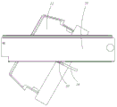
图4是本发明的冰箱在小门打开90°时的部分剖视图;4 is a partial cross-sectional view of the refrigerator of the present invention when the small door is opened by 90°;
图5是图4主动轮与从动轮的配合图;Fig. 5 is the matching diagram of the driving wheel and the driven wheel of Fig. 4;
图6是图4中凸轮的结构示意图;Fig. 6 is the structural representation of the cam in Fig. 4;
图7是图4中小门移除瓶座及其固定结构后沿A-A方向的剖视图。FIG. 7 is a cross-sectional view along the A-A direction of the small door in FIG. 4 after removing the bottle holder and its fixing structure.
具体实施方式Detailed ways
为了使本发明的目的、技术方案和优点更加清楚,下面结合附图和具体实施例对本发明进行详细描述。In order to make the objectives, technical solutions and advantages of the present invention clearer, the present invention will be described in detail below with reference to the accompanying drawings and specific embodiments.
请参阅图1~图4所示,本发明的冰箱100具有箱体1、门体2、由箱体1和门体2围设形成的储藏室,所述储藏室内设有用于存放物品的搁物架11,所述门体2上具有用于存放物品的瓶座20。Referring to FIGS. 1 to 4 , the
请详细参阅图1~图7所示,所述门体2包括具有取物口的第一门体21、与所述第一门体21转动连接以打开或遮蔽所述取物口的第二门体22,所述瓶座20设置于所述第二门体22上,从而仅需要在瓶座20中取放物体时,可以转动打开所述第二门体22,减少漏冷。本实施例中,所述第二门体22具有位于同一直线上的主转轴221和从转轴222,所述主转轴221和所述从转轴222中的一个位于所述第二门体22上端的中间部位、另一个位于所述第二门体22下端的中间部位。本发明通过将所述从转轴222和所述主转轴221设于所述第二门体22的中间部位,从而所述第二门体22转动以打开所述取物口时,还能够遮蔽部分所述取物口,开启的角度较小,能够减少漏冷。Please refer to FIG. 1 to FIG. 7 in detail, the door body 2 includes a
所述门体2还包括驱动组件,所述驱动组件包括设于所述第一门体21上驱动所述主转轴221沿其轴向转动的同时使所述主转轴221向外凸伸出所述第一门体21的驱动机构23、设于所述第一门体21上以限定所述从转轴222移动轨迹的导轨24、连接所述第一门体21与所述第二门体22的弹性件25,所述导轨24的一端与所述第一门体21转动连接,另一端为自由端。在所述第二门体22转动打开所述取物口的过程中,所述从转轴222随着第二门体22在移动的过程中会带动所述导轨24相对所述第一门体21转动,但所述从转轴222不会脱离所述导轨24,该过程中所述弹性件25发生弹性变形对所述第二门体22产生将其拉回遮蔽所述取物口状态的回拉力,在所述驱动机构23、导轨24和所述弹性件25的配合下,所述第二门体22平稳地转动。The door body 2 also includes a drive assembly, which includes a drive assembly provided on the
在需要转动所述第二门体22打开所述取物口时,所述驱动机构23驱动所述主转轴221带动所述第二门体22在转动打开的过程中同时使所述第二门体22向外凸伸出所述第一门体21,从而所述第二门体22上朝向箱体1内转动的一边凸伸入箱体1内的距离很小,不会与箱体1内现有的搁物架11之间形成干涉,也无需在现有的搁物架11与所述第二门体22之间预留间隙,箱体1内的空间利用率较高;并且任意宽度的第二门体22均能够旋转打开而不会与箱体1内的搁物架11相互干涉。该过程中,所述从转轴222随着第二门体22在移动的过程中会带动所述导轨24相对所述第一门体21转动,但所述从转轴222不会脱离所述导轨24,所述弹性件25发生弹性形变产生回拉力,所述驱动机构23、所述导轨24与所述弹性件25的配合使得所述第二门体22平稳地转动。当然,所述弹性件25施力于所述第二门体22的回拉力,还能够在所述第二门体22关闭所述取物口时使其收容于所述取物口内;当然也可以通过所述第二驱动组件驱动所述第二门体22旋转并关闭所述取物口。When the
具体地,请参阅图3和图4所示,所述弹性件25连接于所述第一门体21与所述从转轴222之间,优选地所述弹性件25位于所述导轨24内,不会在第二门体22打开时影响用户自所述取物口取放物品。Specifically, please refer to FIG. 3 and FIG. 4 , the
具体地,请参阅图3~图6所示,所述驱动机构23包括设于所述第一门体21或第二门体22外侧的开关(未图示)、与所述开关通信连接的电机231、与所述电机231传动连接的主动轮232、与所述主动轮232通过固定杆236连接的凸轮233、与所述主动轮232啮合的从动轮234、连接所述从动轮234与所述主转轴221的联轴器235,所述凸轮233上外边缘的不同位置处与所述固定杆236中心轴的距离不同;所述驱动机构23驱动所述主转轴221沿其轴向转动时,所述弹性件25致力于所述第二门体22从而使得所述联轴器235与所述凸轮233始终相抵触。凸轮233上外边缘的不同位置处与所述联轴器235抵触时,所述联轴器235远离所述从动轮234的一端距离所述第一门体21所在平面的距离不同,因此所述凸轮233转动时抵压所述联轴器235使其带动所述主转轴221向外凸伸出所述第一门体21,从而第二门体22在转动的同时向外移动。Specifically, please refer to FIG. 3 to FIG. 6 , the
所述电机231为步进电机231,接收到开关发送的信号后,所述步进电机231通过主动轮232、从动轮234分别驱动凸轮233和所述联轴器235旋转,所述凸轮233抵压所述联轴器235使其向外移动,从而带动所述第二门体22在转动打开的过程中向外移动。The
所述联轴器235包括与所述从动轮234固定连接的第一支架2351、与所述主转轴221固定连接的第二支架2353、与所述第一支架2351和所述第二支架2353均沿上下方向转动连接的连杆2352,所述连杆2352与所述凸轮233的外边缘始终相抵触。所述第一支架2351和所述第二支架2353均包括Y型的固定架、位于所述固定架上的支撑架,所述连杆2352与所述支撑架的中间位置处转动连接,且所述连杆2352可相对所述支撑架上下转动。当所述连杆2352在所述凸轮233的抵压下向外移动时,所述连杆2352靠近所述第二支架2353的一端同时向下移动;反之当所述连杆2352向内移动时,所述连杆2352靠近所述第二支架2353的一端同时向上移动。The
进一步地,所述第二门体22的底部具有收容腔223,所述主转轴221位于所述收容腔223内;所述第二支架2353远离所述连杆2352的一端具有固定块2354,所述固定块2354内具有收容所述主转轴221的通孔(未图示)、沿所述主转轴221的圆周方向定位所述主转轴221与所述通孔的定位结构(未图示);所述凸轮233转动时施力于所述连杆2352,所述连杆2352带动所述第二支架2353转动,所述固定块2354相对所述主转轴221上下移动同时在所述定位结构的作用下带动所述主转轴221转动,所述主转轴221带动所述第二门体22转动;所述驱动机构23还包括连接于所述固定块2354与所述主转轴221或所述收容腔223之间的弹性支撑件224,所述弹性支撑件224在所述第二支架2353上下移动时起到弹性支撑作用,保证所述第二门体22不会下移。Further, the bottom of the
请参阅图4和图6所示,所述凸轮233具有分设于所述固定杆236两侧的第一凸轮块2331、第二凸轮块2332,所述第一凸轮块2331的外边缘至所述固定杆236的距离相同,而沿所述第一凸轮块2331朝向所述第二凸轮块2332的方向,所述第二凸轮块2332的外边缘至所述固定杆236的距离逐渐变大。所述凸轮233沿所述第二凸轮块2332的外边缘的中间位置与所述固定杆236的连线对称设置,且所述第二门体22遮蔽所述取物口时,所述联轴器235与所述第二凸轮块2332的外边缘的中间位置处相抵触,所述第二门体22可以沿两个方向打开或关闭所述取物口。Referring to FIGS. 4 and 6 , the
在需要转动所述第二门体22打开取物口时,所述第一凸轮块2331首先抵压所述连杆2352,该过程中所述第二门体22仅绕所述从转轴222和所述主转轴221转动而未向外移动,便于所述第二门体22的外缘与所述取物口快速分离;当所述第二凸轮块2332抵压所述连杆2352时,所述第二门体22转动的同时向外移动,整个过程的阻力较小。When the
另外,如图7所示,所述第二门体22的周缘具有与所述第一门体21取物口相配合的密封结构26,所述密封结构26为嵌入所述第二门体22周缘的切面为圆弧形的PVC胶垫,在与所述取物口形成面接触的同时,所述第二门体22两个方向转动均能够正常开闭,实现冰箱100的有效保温。In addition, as shown in FIG. 7 , the peripheral edge of the
综上所述,本发明的门体2,通过将所述从转轴222和所述主转轴221设于所述第二门体22的中间部位,从而所述第二门体22转动以打开所述取物口时,还能够遮蔽部分所述取物口,开启的角度较小,能够减少漏冷;并通过所述驱动组件使得所述第二门体22在旋转打开的过程中同时使所述第二门体22向外凸伸出所述第一门体21,从而所述第二门体22上朝向箱体1内转动的一边凸伸入箱体1内的距离很小,不会与箱体1内现有的搁物架11之间形成干涉,也无需在现有的搁物架11与所述第二门体22之间预留间隙,箱体1内的空间利用率较高;并且任意宽度的第二门体22均能够旋转打开而不会与箱体1内的搁物架11相互干涉。To sum up, in the door body 2 of the present invention, by arranging the
以上实施例仅用以说明本发明的技术方案而非限制,尽管参照较佳实施例对本发明进行了详细说明,本领域的普通技术人员应当理解,可以对本发明的技术方案进行修改或者等同替换,而不脱离本发明技术方案的精神和范围。The above embodiments are only used to illustrate the technical solutions of the present invention and not to limit them. Although the present invention has been described in detail with reference to the preferred embodiments, those of ordinary skill in the art should understand that the technical solutions of the present invention can be modified or equivalently replaced. Without departing from the spirit and scope of the technical solutions of the present invention.
Claims (9)
Priority Applications (1)
| Application Number | Priority Date | Filing Date | Title |
|---|---|---|---|
| CN201810063309.3A CN108204706B (en) | 2018-01-23 | 2018-01-23 | Door body and refrigerator having the same |
Applications Claiming Priority (1)
| Application Number | Priority Date | Filing Date | Title |
|---|---|---|---|
| CN201810063309.3A CN108204706B (en) | 2018-01-23 | 2018-01-23 | Door body and refrigerator having the same |
Publications (2)
| Publication Number | Publication Date |
|---|---|
| CN108204706A CN108204706A (en) | 2018-06-26 |
| CN108204706B true CN108204706B (en) | 2020-11-20 |
Family
ID=62606374
Family Applications (1)
| Application Number | Title | Priority Date | Filing Date |
|---|---|---|---|
| CN201810063309.3A Active CN108204706B (en) | 2018-01-23 | 2018-01-23 | Door body and refrigerator having the same |
Country Status (1)
| Country | Link |
|---|---|
| CN (1) | CN108204706B (en) |
Family Cites Families (5)
| Publication number | Priority date | Publication date | Assignee | Title |
|---|---|---|---|---|
| KR20040049676A (en) * | 2002-12-06 | 2004-06-12 | 엘지전자 주식회사 | Mounting structure of home bar in refrigerator |
| CN100523681C (en) * | 2004-07-22 | 2009-08-05 | 阿塞里克股份有限公司 | Cooling device |
| CN101086409B (en) * | 2006-06-06 | 2011-02-02 | 海尔集团公司 | Rotary type refrigerator small door |
| KR20080027648A (en) * | 2006-09-25 | 2008-03-28 | 주식회사 대우일렉트로닉스 | Rotating Home Bar in Refrigerator |
| KR20140019911A (en) * | 2012-08-06 | 2014-02-18 | 동부대우전자 주식회사 | Refrigerator having home bar |
-
2018
- 2018-01-23 CN CN201810063309.3A patent/CN108204706B/en active Active
Also Published As
| Publication number | Publication date |
|---|---|
| CN108204706A (en) | 2018-06-26 |
Similar Documents
| Publication | Publication Date | Title |
|---|---|---|
| CN112878840B (en) | A hinge assembly and an appliance equipped with the hinge assembly | |
| US8025349B2 (en) | Refrigerator with door opening device | |
| WO2019042347A1 (en) | Hinge assembly and refrigerator comprising hinge assembly | |
| KR101508373B1 (en) | Refrigerator | |
| CN106595212B (en) | Drawer appliance and the refrigerator with the drawer appliance | |
| CN108661470A (en) | A hinge assembly and an appliance equipped with the hinge assembly | |
| CN204909136U (en) | A six-bar linkage mechanism | |
| JP2009186141A (en) | refrigerator | |
| CN106679264A (en) | Refrigerator capable of preventing too high energy consumption | |
| CN108204706B (en) | Door body and refrigerator having the same | |
| CN106766636B (en) | Drawer appliance and the refrigerator with the drawer appliance | |
| CN106642964B (en) | Drawer appliance and the refrigerator with the drawer appliance | |
| CN111425099B (en) | Door opening systems and door opening appliances | |
| CN211823374U (en) | Refrigerator and Freezer | |
| CN201653046U (en) | A resettable refrigerator handle | |
| CN206681545U (en) | A kind of hinge component and the utensil for being provided with the hinge component | |
| KR20090080346A (en) | Refrigerator door automatic opening device | |
| CN210383839U (en) | Cleaning machine capable of automatically opening and closing door body | |
| EP4082931B1 (en) | Cover assembly and packaging box | |
| CN205192079U (en) | Bottle seat component and refrigerator | |
| CN203100331U (en) | Rotary distributor | |
| CN105466105A (en) | Refrigerator | |
| CN208905613U (en) | Shoe washing machine | |
| CN105563499A (en) | Meal placing device of intelligent meal sending robot | |
| CN108679914A (en) | A manual automatic door opening and closing structure for refrigerators |
Legal Events
| Date | Code | Title | Description |
|---|---|---|---|
| PB01 | Publication | ||
| PB01 | Publication | ||
| SE01 | Entry into force of request for substantive examination | ||
| SE01 | Entry into force of request for substantive examination | ||
| CB02 | Change of applicant information |
Address after: 266101 No. 1 Haier Road, Laoshan District, Shandong, Qingdao Applicant after: Haier Smart Home Co., Ltd. Address before: 266101 Haier Industrial Park, Haier Road, Laoshan District, Shandong, Qingdao, China Applicant before: Qingdao Haier Joint Stock Co.,Ltd. |
|
| CB02 | Change of applicant information | ||
| GR01 | Patent grant | ||
| GR01 | Patent grant |