CN108071907B - Supporting mechanism and mobile terminal - Google Patents
Supporting mechanism and mobile terminal Download PDFInfo
- Publication number
- CN108071907B CN108071907B CN201611027773.4A CN201611027773A CN108071907B CN 108071907 B CN108071907 B CN 108071907B CN 201611027773 A CN201611027773 A CN 201611027773A CN 108071907 B CN108071907 B CN 108071907B
- Authority
- CN
- China
- Prior art keywords
- transmission gear
- gear rod
- rod
- supporting plate
- supporting
- Prior art date
- Legal status (The legal status is an assumption and is not a legal conclusion. Google has not performed a legal analysis and makes no representation as to the accuracy of the status listed.)
- Active
Links
Images


Classifications
-
- G—PHYSICS
- G06—COMPUTING OR CALCULATING; COUNTING
- G06F—ELECTRIC DIGITAL DATA PROCESSING
- G06F1/00—Details not covered by groups G06F3/00 - G06F13/00 and G06F21/00
- G06F1/16—Constructional details or arrangements
- G06F1/1613—Constructional details or arrangements for portable computers
- G06F1/1633—Constructional details or arrangements of portable computers not specific to the type of enclosures covered by groups G06F1/1615 - G06F1/1626
- G06F1/1675—Miscellaneous details related to the relative movement between the different enclosures or enclosure parts
- G06F1/1681—Details related solely to hinges
-
- F—MECHANICAL ENGINEERING; LIGHTING; HEATING; WEAPONS; BLASTING
- F16—ENGINEERING ELEMENTS AND UNITS; GENERAL MEASURES FOR PRODUCING AND MAINTAINING EFFECTIVE FUNCTIONING OF MACHINES OR INSTALLATIONS; THERMAL INSULATION IN GENERAL
- F16M—FRAMES, CASINGS OR BEDS OF ENGINES, MACHINES OR APPARATUS, NOT SPECIFIC TO ENGINES, MACHINES OR APPARATUS PROVIDED FOR ELSEWHERE; STANDS; SUPPORTS
- F16M11/00—Stands or trestles as supports for apparatus or articles placed thereon ; Stands for scientific apparatus such as gravitational force meters
- F16M11/02—Heads
- F16M11/04—Means for attachment of apparatus; Means allowing adjustment of the apparatus relatively to the stand
- F16M11/043—Allowing translations
-
- E—FIXED CONSTRUCTIONS
- E05—LOCKS; KEYS; WINDOW OR DOOR FITTINGS; SAFES
- E05D—HINGES OR SUSPENSION DEVICES FOR DOORS, WINDOWS OR WINGS
- E05D3/00—Hinges with pins
- E05D3/06—Hinges with pins with two or more pins
- E05D3/18—Hinges with pins with two or more pins with sliding pins or guides
-
- E—FIXED CONSTRUCTIONS
- E05—LOCKS; KEYS; WINDOW OR DOOR FITTINGS; SAFES
- E05F—DEVICES FOR MOVING WINGS INTO OPEN OR CLOSED POSITION; CHECKS FOR WINGS; WING FITTINGS NOT OTHERWISE PROVIDED FOR, CONCERNED WITH THE FUNCTIONING OF THE WING
- E05F1/00—Closers or openers for wings, not otherwise provided for in this subclass
- E05F1/08—Closers or openers for wings, not otherwise provided for in this subclass spring-actuated, e.g. for horizontally sliding wings
- E05F1/10—Closers or openers for wings, not otherwise provided for in this subclass spring-actuated, e.g. for horizontally sliding wings for swinging wings, e.g. counterbalance
- E05F1/12—Mechanisms in the shape of hinges or pivots, operated by springs
-
- F—MECHANICAL ENGINEERING; LIGHTING; HEATING; WEAPONS; BLASTING
- F16—ENGINEERING ELEMENTS AND UNITS; GENERAL MEASURES FOR PRODUCING AND MAINTAINING EFFECTIVE FUNCTIONING OF MACHINES OR INSTALLATIONS; THERMAL INSULATION IN GENERAL
- F16H—GEARING
- F16H1/00—Toothed gearings for conveying rotary motion
- F16H1/02—Toothed gearings for conveying rotary motion without gears having orbital motion
- F16H1/04—Toothed gearings for conveying rotary motion without gears having orbital motion involving only two intermeshing members
- F16H1/06—Toothed gearings for conveying rotary motion without gears having orbital motion involving only two intermeshing members with parallel axes
-
- F—MECHANICAL ENGINEERING; LIGHTING; HEATING; WEAPONS; BLASTING
- F16—ENGINEERING ELEMENTS AND UNITS; GENERAL MEASURES FOR PRODUCING AND MAINTAINING EFFECTIVE FUNCTIONING OF MACHINES OR INSTALLATIONS; THERMAL INSULATION IN GENERAL
- F16H—GEARING
- F16H21/00—Gearings comprising primarily only links or levers, with or without slides
- F16H21/10—Gearings comprising primarily only links or levers, with or without slides all movement being in, or parallel to, a single plane
- F16H21/44—Gearings comprising primarily only links or levers, with or without slides all movement being in, or parallel to, a single plane for conveying or interconverting oscillating or reciprocating motions
-
- F—MECHANICAL ENGINEERING; LIGHTING; HEATING; WEAPONS; BLASTING
- F16—ENGINEERING ELEMENTS AND UNITS; GENERAL MEASURES FOR PRODUCING AND MAINTAINING EFFECTIVE FUNCTIONING OF MACHINES OR INSTALLATIONS; THERMAL INSULATION IN GENERAL
- F16M—FRAMES, CASINGS OR BEDS OF ENGINES, MACHINES OR APPARATUS, NOT SPECIFIC TO ENGINES, MACHINES OR APPARATUS PROVIDED FOR ELSEWHERE; STANDS; SUPPORTS
- F16M11/00—Stands or trestles as supports for apparatus or articles placed thereon ; Stands for scientific apparatus such as gravitational force meters
- F16M11/02—Heads
- F16M11/04—Means for attachment of apparatus; Means allowing adjustment of the apparatus relatively to the stand
-
- G—PHYSICS
- G06—COMPUTING OR CALCULATING; COUNTING
- G06F—ELECTRIC DIGITAL DATA PROCESSING
- G06F1/00—Details not covered by groups G06F3/00 - G06F13/00 and G06F21/00
- G06F1/16—Constructional details or arrangements
- G06F1/1613—Constructional details or arrangements for portable computers
- G06F1/1615—Constructional details or arrangements for portable computers with several enclosures having relative motions, each enclosure supporting at least one I/O or computing function
- G06F1/1616—Constructional details or arrangements for portable computers with several enclosures having relative motions, each enclosure supporting at least one I/O or computing function with folding flat displays, e.g. laptop computers or notebooks having a clamshell configuration, with body parts pivoting to an open position around an axis parallel to the plane they define in closed position
-
- G—PHYSICS
- G06—COMPUTING OR CALCULATING; COUNTING
- G06F—ELECTRIC DIGITAL DATA PROCESSING
- G06F1/00—Details not covered by groups G06F3/00 - G06F13/00 and G06F21/00
- G06F1/16—Constructional details or arrangements
- G06F1/1613—Constructional details or arrangements for portable computers
- G06F1/1633—Constructional details or arrangements of portable computers not specific to the type of enclosures covered by groups G06F1/1615 - G06F1/1626
- G06F1/1675—Miscellaneous details related to the relative movement between the different enclosures or enclosure parts
- G06F1/1679—Miscellaneous details related to the relative movement between the different enclosures or enclosure parts for locking or maintaining the movable parts of the enclosure in a fixed position, e.g. latching mechanism at the edge of the display in a laptop or for the screen protective cover of a PDA
-
- G—PHYSICS
- G06—COMPUTING OR CALCULATING; COUNTING
- G06F—ELECTRIC DIGITAL DATA PROCESSING
- G06F1/00—Details not covered by groups G06F3/00 - G06F13/00 and G06F21/00
- G06F1/16—Constructional details or arrangements
- G06F1/1613—Constructional details or arrangements for portable computers
- G06F1/1633—Constructional details or arrangements of portable computers not specific to the type of enclosures covered by groups G06F1/1615 - G06F1/1626
- G06F1/1675—Miscellaneous details related to the relative movement between the different enclosures or enclosure parts
- G06F1/1683—Miscellaneous details related to the relative movement between the different enclosures or enclosure parts for the transmission of signal or power between the different housings, e.g. details of wired or wireless communication, passage of cabling
-
- H—ELECTRICITY
- H04—ELECTRIC COMMUNICATION TECHNIQUE
- H04M—TELEPHONIC COMMUNICATION
- H04M1/00—Substation equipment, e.g. for use by subscribers
- H04M1/02—Constructional features of telephone sets
-
- H—ELECTRICITY
- H04—ELECTRIC COMMUNICATION TECHNIQUE
- H04M—TELEPHONIC COMMUNICATION
- H04M1/00—Substation equipment, e.g. for use by subscribers
- H04M1/02—Constructional features of telephone sets
- H04M1/0202—Portable telephone sets, e.g. cordless phones, mobile phones or bar type handsets
- H04M1/026—Details of the structure or mounting of specific components
- H04M1/0266—Details of the structure or mounting of specific components for a display module assembly
- H04M1/0268—Details of the structure or mounting of specific components for a display module assembly including a flexible display panel
-
- H—ELECTRICITY
- H05—ELECTRIC TECHNIQUES NOT OTHERWISE PROVIDED FOR
- H05K—PRINTED CIRCUITS; CASINGS OR CONSTRUCTIONAL DETAILS OF ELECTRIC APPARATUS; MANUFACTURE OF ASSEMBLAGES OF ELECTRICAL COMPONENTS
- H05K5/00—Casings, cabinets or drawers for electric apparatus
- H05K5/0086—Casings, cabinets or drawers for electric apparatus portable, e.g. battery operated apparatus
-
- H—ELECTRICITY
- H05—ELECTRIC TECHNIQUES NOT OTHERWISE PROVIDED FOR
- H05K—PRINTED CIRCUITS; CASINGS OR CONSTRUCTIONAL DETAILS OF ELECTRIC APPARATUS; MANUFACTURE OF ASSEMBLAGES OF ELECTRICAL COMPONENTS
- H05K5/00—Casings, cabinets or drawers for electric apparatus
- H05K5/02—Details
- H05K5/0217—Mechanical details of casings
- H05K5/0226—Hinges
-
- E—FIXED CONSTRUCTIONS
- E05—LOCKS; KEYS; WINDOW OR DOOR FITTINGS; SAFES
- E05Y—INDEXING SCHEME ASSOCIATED WITH SUBCLASSES E05D AND E05F, RELATING TO CONSTRUCTION ELEMENTS, ELECTRIC CONTROL, POWER SUPPLY, POWER SIGNAL OR TRANSMISSION, USER INTERFACES, MOUNTING OR COUPLING, DETAILS, ACCESSORIES, AUXILIARY OPERATIONS NOT OTHERWISE PROVIDED FOR, APPLICATION THEREOF
- E05Y2999/00—Subject-matter not otherwise provided for in this subclass
Landscapes
- Engineering & Computer Science (AREA)
- General Engineering & Computer Science (AREA)
- Computer Hardware Design (AREA)
- Theoretical Computer Science (AREA)
- Mechanical Engineering (AREA)
- Physics & Mathematics (AREA)
- General Physics & Mathematics (AREA)
- Human Computer Interaction (AREA)
- Microelectronics & Electronic Packaging (AREA)
- Signal Processing (AREA)
- Mathematical Physics (AREA)
- Computer Networks & Wireless Communication (AREA)
- Telephone Set Structure (AREA)
Abstract
本发明实施例公开了一种支撑机构,包括:第一托板、第二托板、以及连接所述第一托板和所述第二托板的传动机构;当所述支撑机构处于支撑状态时,所述第一托板与所述第二托板处于第一相对位置,形成一个支撑面。本发明实施例同时公开了一种移动终端。

An embodiment of the present invention discloses a supporting mechanism, comprising: a first supporting plate, a second supporting plate, and a transmission mechanism connecting the first supporting plate and the second supporting plate; when the supporting mechanism is in a supporting state When the first support plate and the second support plate are in a first relative position, a support surface is formed. The embodiment of the present invention also discloses a mobile terminal.
Description
Technical Field
The invention relates to the field of electronic equipment, in particular to a supporting mechanism and a mobile terminal.
Background
With the development of the internet and informatization, electronic products have become a necessity in daily life of people. The existing electronic product modeling gradually tends to be uniform, and the appearance of the electronic product modeling is basically the appearance of a straight plate machine. Meanwhile, under different use scenes, when people want to obtain good use experience, the size of the display screen of the electronic product and the size of the volume of the electronic product can conflict, for example, the electronic product with a small volume is convenient to carry, but the inevitable size of the display screen can be small, the viewing experience is affected, and the user experience is reduced invisibly.
At present, a flexible screen with a flexible characteristic has been successfully produced in mass, and can be used as a display screen of an electronic product to solve the contradiction between the size of the display screen of the electronic product and the size of the mobile terminal. Therefore, what is needed to be solved is how to utilize the deformable characteristic of a flexible display screen in an electronic product to realize a display screen with a larger size under the same volume, so as to provide better service for users.
Disclosure of Invention
In view of this, embodiments of the present invention desirably provide a supporting mechanism and a mobile terminal, so as to support a flexible screen of the mobile terminal in an unfolded state, and further set a large-size display screen without changing a volume of the mobile terminal, so as to consider portability and large-size display of the mobile terminal, and improve user experience.
In order to achieve the purpose, the technical scheme of the invention is realized as follows:
in a first aspect, an embodiment of the present invention provides a support mechanism, which at least includes: the device comprises a first supporting plate, a second supporting plate and a transmission mechanism for connecting the first supporting plate and the second supporting plate; when the supporting mechanism is in a supporting state, the first supporting plate and the second supporting plate are in a first relative position to form a supporting surface.
In a second aspect, an embodiment of the present invention provides a mobile terminal, where the mobile terminal includes: the display device comprises a first body, a second body connected with the first body, the supporting mechanism and the display screen, wherein the supporting mechanism and the display screen are arranged on the first body; wherein, the display screen at least includes: a fixed portion fixed to the first body and/or the second body, and a deformable deformation portion; the supporting mechanism is arranged on the second body; in the process that the first body rotates towards the first direction, the first body drives the supporting mechanism to move relative to the second body; when the mobile terminal is in an unfolded state, the fixed part and the deformation part are in the same plane, and the support mechanism supports the deformation part.
The embodiment of the invention provides a supporting mechanism and a mobile terminal, wherein the supporting mechanism comprises: the first supporting plate, the second supporting plate, the first transmission gear rod, the second transmission gear rod and the pushing rod are arranged on the first supporting plate; when the pushing rod is subjected to external force, the pushing rod drives the first transmission gear rod to slide relative to the first supporting plate and simultaneously drives the first transmission gear rod to rotate towards the second direction; in the process that the first transmission gear rod rotates towards the second direction, the first gear is meshed with the second gear, the first transmission gear rod drives the second transmission gear rod to slide relative to the second supporting plate, and meanwhile, the second transmission gear rod is driven to rotate towards the first direction opposite to the second direction, so that the first supporting plate rotates towards the first direction, the second supporting plate rotates towards the second direction until the first supporting plate and the second supporting plate are parallel and level, and a plane is formed. Then, if the supporting mechanism according to the embodiment of the present invention is applied to a mobile terminal, a plane formed by the first supporting plate and the second supporting plate can be used for supporting a flexible screen in the mobile terminal, and when the mobile terminal is in an unfolded state, the supporting mechanism is used for supporting the flexible screen of the mobile terminal, so that a large-size display screen is set without changing the volume of the mobile terminal, the portability and the large-size display of the mobile terminal are both considered, and the user experience is improved.
Drawings
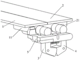
FIG. 1 is a schematic structural diagram of a supporting mechanism according to a first embodiment of the present invention;
fig. 2 is a schematic diagram illustrating a relative position relationship between a first transmission gear rod and a second transmission gear rod according to a first embodiment of the present invention;
fig. 3A to 3B are schematic views illustrating a state of a supporting mechanism according to a first embodiment of the invention;
fig. 4 is a schematic structural diagram of a fixing base according to a first embodiment of the invention;
fig. 5 is a schematic structural diagram of a mobile terminal according to a second embodiment of the present invention;
fig. 6 is a schematic structural diagram of a display screen in a second embodiment of the present invention;
FIG. 7 is a schematic structural diagram of a rotating shaft according to a second embodiment of the present invention;
FIG. 8 is a schematic view showing the relative relationship between the shaft and the pushing rod according to the second embodiment of the present invention;
fig. 9A to 9B are schematic views of states of a mobile terminal according to a second embodiment of the present invention.
Detailed Description
The technical solution in the embodiments of the present invention will be clearly and completely described below with reference to the accompanying drawings in the embodiments of the present invention.
Example one
An embodiment of the present invention provides a supporting mechanism, which at least includes: the device comprises a first supporting plate, a second supporting plate and a transmission mechanism for connecting the first supporting plate and the second supporting plate; when the supporting mechanism is in a supporting state, the first supporting plate and the second supporting plate are in a first relative position to form a supporting surface.
Further, when the transmission mechanism is acted by external force, the transmission mechanism drives the first supporting plate to rotate towards the first direction and drives the second supporting plate to rotate towards the second direction until the first supporting plate and the second supporting plate are parallel and level to form a supporting surface, and the first direction is opposite to the second direction.
In a specific process, referring to fig. 1, the supporting mechanism may include: the device comprises a first supporting plate 1, a second supporting plate 2, a first transmission gear rod 3, a second transmission gear rod 4 and a push rod 5; wherein, the first end swing joint of first transmission gear pole 3 is provided with first gear on the terminal surface of the second end of first transmission gear pole 3 in the lower surface of first layer board 1, and first transmission gear pole 3 is connected with catch bar 5, and the third end swing joint of second transmission gear pole 4 is provided with the second gear on the terminal surface of the fourth end of second transmission gear pole 4 in the lower surface of second layer board 2.
When the pushing rod is subjected to external force, the pushing rod drives the first transmission gear rod to slide relative to the first supporting plate and simultaneously drives the first transmission gear rod to rotate towards the second direction; in the process that the first transmission gear rod rotates towards the second direction, the first transmission gear rod is meshed with the second gear through the first gear, the first transmission gear rod drives the second transmission gear rod to slide relative to the second supporting plate, and meanwhile, the second transmission gear rod is driven to rotate towards the first direction, so that the first supporting plate rotates towards the first direction, and the second supporting plate rotates towards the second direction until the first supporting plate and the second supporting plate are parallel and level to form a plane.
Here, the first direction is opposite to the second direction. In the embodiment of the present invention, the first direction may be counterclockwise, and the second direction may be clockwise.
The support mechanism will be described in detail below.
First, referring to fig. 2, a first sliding chute 11 is formed in the lower surface of the first supporting plate 1, a first end of the first transmission gear rod 3 is disposed in the first sliding chute 11, and a first gear is disposed on an end surface 3021 of the second end 302 of the first transmission gear rod 3; a second sliding chute 21 is formed in the lower surface of the second supporting plate 2, a third end of the second transmission gear rod 4 is arranged in the second sliding chute 21, and a second gear is arranged on an end surface 4021 of a fourth end 402 of the second transmission gear rod 4;
in a specific implementation process, the first transmission gear rod 3 has a first end 301 and a second end 302, wherein the first end 301 is provided with a solid shaft, i.e. a first shaft, a fixed end of the shaft is fixed on the first end, and a free end of the shaft extends into the first sliding groove, so that the first shaft slides in the first sliding groove to drive the first transmission gear rod to slide in the first sliding groove; a first gear is arranged on the end face 3021 of the second end 302;
correspondingly, the second transmission gear rod 4 has a third end 401 and a fourth end 402, wherein the third end 402 is provided with a solid shaft, i.e. a second shaft, the fixed end of the shaft is fixed on the third end, and the free end extends into the second sliding slot, so that the second shaft slides in the second sliding slot to drive the second transmission gear rod to slide in the second sliding slot; a second gear is provided on the end surface 4021 of the fourth end 402.
It should be noted that the end surface of the second end and the end surface of the fourth end may be curved surfaces with the same radius and the same curvature, and at this time, the number of teeth of the first gear is the same as that of the second gear; of course, the end surface of the second end and the end surface of the fourth end may also be curved surfaces with different radii and the same curvature, the radius of the end surface of the second end is smaller than the radius of the end surface of the fourth end, or the radius of the end surface of the second end is larger than the radius of the end surface of the fourth end, and at this time, the number of teeth of the first gear is different from that of the second gear. Of course, there may be other cases, and the present invention is not particularly limited.
Further, still referring to fig. 2, the first transmission gear rod 3 further includes a third end 303, a through hole is formed in the third end 303, a through hole is also formed in the push rod, and a solid shaft passes through the through hole in the third end and the through hole in the push rod to fix the push rod and the first transmission gear rod together. In addition, the push rod and the first transmission gear rod are fixed through the shaft, so that the push rod and the first transmission gear rod can rotate mutually.
In practical application, in order to protect the first shaft and the second shaft and prevent the first shaft and the second shaft from being worn in the working process of the supporting mechanism, the first protection piece can be sleeved on the first shaft, and the second protection piece can be sleeved on the second shaft. Here, each of the first protector and the second protector is made of a material having a first value of friction coefficient, such as nylon, rubber, or the like. Of course, it should be understood by those skilled in the art that the first protection member and the second protection member may be made of other materials, and the embodiment of the present invention is not particularly limited thereto.
Therefore, when the push rod is subjected to external force to drive the first transmission gear rod to slide relative to the first supporting plate, the push rod simultaneously drives the first transmission gear rod to rotate towards the second direction, then, in the process that the first transmission gear rod rotates towards the second direction, the first gear is meshed with the second gear, at the moment, the first transmission gear rod drives the second transmission gear rod to slide relative to the second supporting plate, and simultaneously drives the second transmission gear rod to rotate towards the first direction, so that the first supporting plate 1 rotates towards the first direction, the second supporting plate rotates towards the second direction until the first supporting plate 1 and the second supporting plate 2 are parallel and level as shown in fig. 3A, a plane is formed, and at the moment, the supporting mechanism is in a supporting state.
In another embodiment of the present invention, referring to fig. 2, the first transmission gear rod 3 may further be provided with a first positioning column; a second positioning column 41 can be further arranged on the second transmission gear rod 4;
accordingly, with reference to fig. 1 and 2, the supporting mechanism may further include: one end of the spring 6 is sleeved on the first positioning column, and the other end of the spring is sleeved on the second positioning column 41; then, in the process that the first transmission gear rod 3 drives the second transmission gear rod 4 to rotate towards the first direction, the spring 6 is compressed; then, after the external force applied to the pushing rod 5 is removed, the spring generates a restoring force to act on the first transmission gear rod 3 and the second transmission gear rod 4, respectively, so that the first gear is disengaged from the second gear, the first supporting plate 1 rotates in the second direction, and the second supporting plate 2 rotates in the first direction, that is, the first supporting plate and the second supporting plate are separated.
In practical applications, referring to fig. 4, the supporting mechanism further includes: a fixed seat 7, wherein a limit groove 71 is formed on the fixed seat 7, and the first transmission gear rod and the second transmission gear rod pass through the limit groove 71; here, the opening of the stopper groove is larger than the sum of the widths of the first and second transmission gear bars so that the first and second transmission gear bars still have a sliding space after passing through the stopper groove. Then, referring to fig. 3B and 4, after the first gear is disengaged from the second gear, the first transmission gear lever 3 slides in the first sliding groove 11 and rotates toward the first direction by the restoring force; the second transmission gear rod 4 slides in the second sliding groove 21 under the action of restoring force and rotates towards the second direction until the first transmission gear rod 3 and the second transmission gear rod 4 are clamped with the opening of the limiting groove 71, at the moment, the first gear and the second gear are in point contact, and the supporting mechanism restores the contraction state.
In practical applications, the opening of the limiting groove may be rectangular, oval, elliptical, or the like, and the embodiment of the present invention is not limited specifically.
Further, still referring to fig. 4, the above-mentioned limiting groove 71 has a first sidewall 711 and a second sidewall 712 parallel to each other, and a third sidewall 713 and a fourth sidewall 714 connecting the first sidewall 711 and the second sidewall 712, the third sidewall 713 and the fourth sidewall 714 are opposite, the third sidewall 713 is inclined at a first angle, the fourth sidewall 714 is inclined at a second angle, and the first angle and the second angle are complementary angles; when the first transmission gear rod and the second transmission gear rod are clamped with the opening of the limiting groove, the third side wall supports the first transmission gear rod, and the fourth side wall supports the second transmission gear rod.
In a specific implementation process, the third sidewall and the fourth sidewall may not be inclined and perpendicular to the first sidewall and the second sidewall, and the embodiment of the present invention is not particularly limited.
Further, as shown in fig. 1, the upper surface of the fixing seat 7 is further provided with a translation gasket 72; when the first transmission gear rod and the second transmission gear rod are clamped with the openings of the limiting grooves, the translation gasket provides friction force for the first transmission gear rod and the second transmission gear rod.
Further, as shown in fig. 1, the top of the push rod 5 is also provided with a gasket 51; when the first transmission gear rod and the second transmission gear rod penetrate through the limiting grooves and the push rod moves under the action of external force, the gasket is used for increasing the friction force between the push rod and the fixing seat.
Furthermore, at least one rotating shaft can be arranged at one end of the first supporting plate far away from the second supporting plate, and the at least one rotating shaft is used for being connected with the shell of the mobile terminal when the supporting mechanism is fixed on the mobile terminal.
The operation of the above-described support mechanism will be described below.
When the supporting mechanism is in a contracted state as shown in fig. 3B, the pushing rod 5 is under the action of an external force to drive the first transmission gear rod 3 to slide relative to the first supporting plate 1 in a direction close to the second transmission gear rod 4, and simultaneously drive the first transmission gear rod 3 to rotate in a second direction; in the process that the first transmission gear rod 3 rotates towards the second direction, the first gear is meshed with the second gear, the first transmission gear rod 3 drives the second transmission gear rod 4 to slide towards the direction close to the first transmission gear rod 3 relative to the second supporting plate 2, and simultaneously drives the second transmission gear rod 4 to rotate towards the first direction, so that the spring 6 is compressed, the first supporting plate 1 rotates towards the first direction, the second supporting plate 2 rotates towards the second direction until the first supporting plate and the second supporting plate are parallel and level to form a plane, and at the moment, the supporting mechanism is in a supporting state as shown in fig. 3A.
Next, the external force applied to the pushing rod 5 is removed, at this time, the spring 6 generates a restoring force, which acts on the first transmission gear rod 3 and the second transmission gear rod 4, respectively, so that the first transmission gear rod 3 slides relative to the first supporting plate 1 in a direction away from the second transmission gear rod 4, and simultaneously rotates in the first direction, and the second transmission gear rod 4 slides relative to the second supporting plate 2 in a direction away from the first transmission gear rod 3, and simultaneously rotates in the second direction, until the first transmission gear rod 3 and the second transmission gear rod 4 are engaged with the opening of the limiting groove 71, at this time, the first gear and the second gear present a point contact, and the supporting mechanism returns to the retracted state shown in fig. 3B.
Therefore, if the support mechanism provided by the embodiment of the invention is applied to the mobile terminal, the plane formed by the first supporting plate and the second supporting plate can be used for supporting the flexible screen in the mobile terminal, and when the mobile terminal is not used, the flexible screen can be accommodated in the mobile terminal, and when the mobile terminal is used, the flexible screen can be unfolded and supported by the support mechanism, so that the large-size display screen can be arranged on the mobile terminal under the condition of not changing the size of the mobile terminal, the portability and the large-size display of the mobile terminal can be considered, and the user experience can be improved.
Example two
Based on the same inventive concept, the embodiment of the present invention further provides a mobile terminal, as shown in fig. 5 (the blank on one side of the curve is the other components of the terminal), where the mobile terminal includes: a first body 501, a second body 502 rotatably connected with the first body 501, a supporting mechanism 503 in one or more embodiments, and a display 504;
here, referring to fig. 6, the display 504 includes at least: a fixing portion 5041 fixed to the first body and/or the second body, and a deformable deformation portion 5042; the supporting mechanism 503 is disposed on the second body 502.
Further, still referring to fig. 5, the second body 502 is provided with a receiving groove 5021, and when the terminal is in the fastened state, the deformed portion is received in the receiving groove 5021. The supporting mechanism 503 is accommodated in the accommodating groove 5021 and fixed on the inner wall of the accommodating groove 5021 through the fixing seat.
Further, still referring to fig. 1, at least one rotating shaft 12 may be further disposed on an end of the first supporting plate 1 away from the second supporting plate 2, and the at least one rotating shaft is connected to an inner wall of the accommodating groove.
Further, the mobile terminal further includes: the second body is rotatably connected with the first body through the at least one rotating shaft.
Specifically, referring to fig. 7, a first free end of the rotating shaft 505 defines at least one first assembly hole 5051, and a second free end of the rotating shaft 505 defines at least one second assembly hole 5052; correspondingly, the first body 501 is provided with at least one riveting column, the riveting column can be connected with the first assembly hole 5051 in a riveting mode, the second body 501 is provided with at least one mounting seat, and the mounting seat can be connected with the second assembly hole 5052 in a riveting mode.
Preferably, as shown in fig. 8, a bayonet 5053 is disposed on the shaft sleeve of the rotating shaft 505 for engaging with the push rod 5 in the supporting mechanism, so that when the rotating shaft 505 rotates, the bayonet 5053 applies an external force to the push rod 5 to enable the push rod 5 to drive the first transmission gear rod to move and further drive the second transmission gear rod to move, and finally, the supporting mechanism is in a supporting state, and a plane formed by the first supporting plate and the second supporting plate is used for supporting a deformation portion of the display screen.
Further, the first body further includes: the at least one first magnetic piece is accommodated in a first groove formed in the first body; the second body further includes: and the at least one second magnetic piece is accommodated in a second groove formed in the inner wall of the accommodating groove. When the mobile terminal is in a buckling state, the at least one first magnetic piece and the at least one second magnetic piece are adsorbed to fix the first body and the second body.
Here, the at least one second magnetic member corresponds to the at least one first magnetic member in one-to-one correspondence, and the accommodating groove of the second body is opened at one end connected to the first body, so that the first groove formed in the first body is located at one end connected to the second body.
In practical application, the first magnetic member on the first body may be a magnet, and correspondingly, the second magnetic member on the second body may be an iron block or a magnet with opposite magnetism to the first magnetic member on the first body; the second magnetic member on the second body is a magnet, and correspondingly, the first magnetic member on the first body may be an iron block or a magnet having a magnetic property opposite to that of the second magnetic member on the second body, and of course, the first magnetic member on the first body and the second magnetic member on the second body may also be other magnetic members, and the invention is not particularly limited.
Further, the first body further includes: the first structure component and the first shell, wherein a third groove is formed in the outer side of the first structure component, and an adhesive is contained in the third groove; the first structural member is fixed to the first housing by an adhesive. The second body further includes: the second structure piece and the second shell, wherein a fourth groove is formed in the outer side of the second structure piece, and an adhesive is contained in the fourth groove; the second structural member is fixed with the second shell through an adhesive; accordingly, the fixing portion of the display screen is fixed to the first structural member and/or the second structural member, and electronic devices such as a circuit board, a data line, a speaker, a power supply, various interfaces, and the like may be further disposed in the accommodating space formed by the first structural member and the first housing, and electronic devices such as a circuit board, a data line, a speaker, a power supply, various interfaces, and the like may also be disposed in the accommodating space formed by the second structural member and the second housing.
Next, the movement process of each component when the mobile terminal is from the snap-fit state to the unfolded state is described.
When the mobile terminal is in a locked state as shown in fig. 9A (the blank on one side of the curve is the other part of the terminal), the first body 501 and the second body 502 are parallel and opposite, accordingly, the fixed portion of the display screen fixed on the first body is parallel and opposite to the fixed portion of the display screen fixed on the second body, the deformable portion of the display screen is accommodated in the accommodating groove formed on the second body, the supporting mechanism is in a contracted state, the first supporting plate and the second supporting plate are obliquely opposite, the deformable portion 5042 is located between the first supporting plate and the second supporting plate, and the push rod is not in contact with the shaft sleeve of the rotating shaft.
When a user wants to use the mobile terminal, the mobile terminal is changed from the buckling state to the unfolding state, and at the moment, the user applies external force to the first body by hand, so that the first body rotates anticlockwise relative to the second body. At this time, the shaft sleeve of the rotating shaft rotates relative to the shaft, the shaft sleeve of the rotating shaft gradually approaches the push rod until contacting with the push rod, at this time, the supporting mechanism 503 is still in a contracted state, the mobile terminal is in an intermediate state, and the first body and the second body are 90 degrees.
As the first body continues to rotate anticlockwise relative to the second body, the shaft sleeve applies external force to the push rod to drive the first transmission gear rod to slide relative to the first supporting plate in a direction close to the second transmission gear rod, and simultaneously drive the first transmission gear rod to rotate clockwise; in the process of clockwise rotation of the first transmission gear rod, the first gear is meshed with the second gear, the first transmission gear rod drives the second transmission gear rod to slide towards the direction close to the first transmission gear rod relative to the second supporting plate, and simultaneously drives the second transmission gear rod to rotate anticlockwise so as to compress the spring, the first supporting plate rotates anticlockwise, the second supporting plate rotates clockwise until the first supporting plate is flush with the second supporting plate to form a plane so as to support the deformation part, at the moment, the supporting mechanism is in a supporting state, the mobile terminal is in an unfolding state as shown in fig. 9B (the blank on one side of the curve is other parts at the terminal), and the first body 501 and the second body 502 are 180 degrees.
When the user uses the mobile terminal, the mobile terminal is buckled, at the moment, the shaft sleeve of the rotating shaft rotates fast relative to the shaft, so that the external force applied on the push rod is removed, at the moment, the spring generates restoring force to act on the first transmission gear rod and the second transmission gear rod respectively, so that the first transmission gear rod slides relative to the first supporting plate in the direction away from the second transmission gear rod, meanwhile, the second transmission gear rod rotates anticlockwise, the second transmission gear rod slides relative to the second supporting plate in the direction far away from the first transmission gear rod, simultaneously clockwise rotates until the first transmission gear rod and the second transmission gear rod are clamped with the opening of the limiting groove, at the moment, the first gear and the second gear are in point contact, the supporting mechanism returns to the retracted state, the mobile terminal is in the locked state as shown in fig. 9A (the blank on one side of the curve is the other part of the terminal), and the first body 501 and the second body 502 are at 0 °.
While preferred embodiments of the present invention have been described, additional variations and modifications in those embodiments may occur to those skilled in the art once they learn of the basic inventive concepts. Therefore, it is intended that the appended claims be interpreted as including preferred embodiments and all such alterations and modifications as fall within the scope of the invention.
It will be apparent to those skilled in the art that various changes and modifications may be made in the present invention without departing from the spirit and scope of the invention. Thus, if such modifications and variations of the present invention fall within the scope of the claims of the present invention and their equivalents, the present invention is also intended to include such modifications and variations.
Claims (8)
Priority Applications (3)
| Application Number | Priority Date | Filing Date | Title |
|---|---|---|---|
| CN201611027773.4A CN108071907B (en) | 2016-11-17 | 2016-11-17 | Supporting mechanism and mobile terminal |
| PCT/CN2017/088217 WO2018090608A1 (en) | 2016-11-17 | 2017-06-14 | Support mechanism and mobile terminal |
| US16/413,717 US10716228B2 (en) | 2016-11-17 | 2019-05-16 | Support mechanism and mobile terminal |
Applications Claiming Priority (1)
| Application Number | Priority Date | Filing Date | Title |
|---|---|---|---|
| CN201611027773.4A CN108071907B (en) | 2016-11-17 | 2016-11-17 | Supporting mechanism and mobile terminal |
Publications (2)
| Publication Number | Publication Date |
|---|---|
| CN108071907A CN108071907A (en) | 2018-05-25 |
| CN108071907B true CN108071907B (en) | 2021-02-09 |
Family
ID=62145828
Family Applications (1)
| Application Number | Title | Priority Date | Filing Date |
|---|---|---|---|
| CN201611027773.4A Active CN108071907B (en) | 2016-11-17 | 2016-11-17 | Supporting mechanism and mobile terminal |
Country Status (3)
| Country | Link |
|---|---|
| US (1) | US10716228B2 (en) |
| CN (1) | CN108071907B (en) |
| WO (1) | WO2018090608A1 (en) |
Families Citing this family (26)
| Publication number | Priority date | Publication date | Assignee | Title |
|---|---|---|---|---|
| JP6776460B2 (en) * | 2017-05-17 | 2020-10-28 | オッポ広東移動通信有限公司Guangdong Oppo Mobile Telecommunications Corp., Ltd. | Foldable mobile terminal |
| WO2018210194A1 (en) * | 2017-05-17 | 2018-11-22 | Oppo广东移动通信有限公司 | Foldable mobile terminal |
| WO2018210196A1 (en) | 2017-05-17 | 2018-11-22 | Oppo广东移动通信有限公司 | Foldable mobile terminal |
| EP3627802B1 (en) | 2017-05-17 | 2021-08-04 | Guangdong Oppo Mobile Telecommunications Corp., Ltd. | Foldable mobile terminal |
| WO2018210187A1 (en) | 2017-05-17 | 2018-11-22 | Oppo广东移动通信有限公司 | Folding mechanism, folding mechanism assembly, and foldable mobile terminal |
| EP3624430B1 (en) | 2017-05-17 | 2022-05-11 | Guangdong Oppo Mobile Telecommunications Corp., Ltd. | Foldable mobile terminal |
| KR102421304B1 (en) * | 2017-09-18 | 2022-07-18 | 삼성디스플레이 주식회사 | Supporting member and display apparatus including the same |
| WO2019070293A1 (en) * | 2017-10-06 | 2019-04-11 | Hewlett-Packard Development Company, L.P. | Hinge assemblies |
| USD904368S1 (en) | 2018-08-01 | 2020-12-08 | Samsung Electronics Co., Ltd. | Mobile phone |
| USD902900S1 (en) | 2018-08-01 | 2020-11-24 | Samsung Electronics Co., Ltd. | Mobile phone |
| USD904367S1 (en) * | 2018-08-01 | 2020-12-08 | Samsung Electronics Co., Ltd. | Mobile phone |
| USD905029S1 (en) * | 2018-08-01 | 2020-12-15 | Samsung Electronics Co., Ltd. | Mobile phone |
| US10895894B2 (en) * | 2018-12-25 | 2021-01-19 | Compal Electronics, Inc. | Electronic device |
| US11023009B2 (en) * | 2019-02-12 | 2021-06-01 | Samsung Display Co., Ltd. | Folding member and display device including the same |
| CN111696432B (en) * | 2019-03-11 | 2022-05-27 | 深圳市长盈精密技术股份有限公司 | Rotating mechanism, folding mechanism and folding display device |
| WO2021007750A1 (en) * | 2019-07-15 | 2021-01-21 | 深圳市柔宇科技有限公司 | Folding device and electronic apparatus |
| CN110459131A (en) * | 2019-07-30 | 2019-11-15 | 武汉华星光电半导体显示技术有限公司 | foldable display device |
| KR20210072857A (en) * | 2019-12-09 | 2021-06-18 | 삼성디스플레이 주식회사 | Display device |
| CN113141422B (en) * | 2020-01-19 | 2022-09-16 | 华为技术有限公司 | Foldable mobile terminal |
| US11044825B1 (en) * | 2019-12-18 | 2021-06-22 | Wuhan China Star Optoelectronics Semiconductor Display Technology Co., Ltd. | Foldable display device |
| CN111246697B (en) * | 2020-03-06 | 2021-01-22 | 昆山工研院新型平板显示技术中心有限公司 | Rotating shaft assembly, display module and display equipment |
| US11181942B1 (en) * | 2020-07-22 | 2021-11-23 | Wuhan China Star Optoelectronics Semiconductor Display Technology Co., Ltd. | Foldable display device |
| KR20220099182A (en) * | 2021-01-05 | 2022-07-13 | 삼성디스플레이 주식회사 | Display apparatus |
| CN112887465B (en) * | 2021-01-28 | 2023-04-25 | 维沃移动通信有限公司 | Electronic equipment |
| CN112995793B (en) * | 2021-03-01 | 2022-09-09 | 北京广厦网络技术股份公司 | Movable 5G communication base station |
| CN114285923B (en) * | 2021-12-31 | 2024-12-20 | 南京市开门柜通讯设备有限公司 | A mobile communication device |
Family Cites Families (9)
| Publication number | Priority date | Publication date | Assignee | Title |
|---|---|---|---|---|
| TWI347160B (en) * | 2008-09-22 | 2011-08-11 | Htc Corp | Handheld electronic device |
| US8698737B2 (en) * | 2010-07-08 | 2014-04-15 | Nokia Corporation | Flexible apparatus |
| KR101148397B1 (en) * | 2010-08-17 | 2012-05-23 | 주식회사 팬택 | Mobile Device |
| US20140211108A1 (en) * | 2013-01-28 | 2014-07-31 | Kabushiki Kaisha Toshiba | Electronic Device and Stand for Electronic Device |
| KR102322377B1 (en) * | 2014-12-31 | 2021-11-05 | 엘지디스플레이 주식회사 | Foldable display apparatus |
| CN205510132U (en) * | 2016-02-03 | 2016-08-24 | 杭州安费诺飞凤通信部品有限公司 | Flexible screen supporting mechanism and mobile terminal |
| CN205596165U (en) * | 2016-03-29 | 2016-09-21 | 杭州安费诺飞凤通信部品有限公司 | Flexible screen mobile terminal's hinge and flexible screen mobile terminal |
| CN206323416U (en) * | 2016-11-17 | 2017-07-11 | 中兴通讯股份有限公司 | A kind of supporting mechanism and mobile terminal |
| CN206350038U (en) * | 2016-11-17 | 2017-07-21 | 中兴通讯股份有限公司 | A kind of supporting mechanism and mobile terminal |
-
2016
- 2016-11-17 CN CN201611027773.4A patent/CN108071907B/en active Active
-
2017
- 2017-06-14 WO PCT/CN2017/088217 patent/WO2018090608A1/en not_active Ceased
-
2019
- 2019-05-16 US US16/413,717 patent/US10716228B2/en active Active
Also Published As
| Publication number | Publication date |
|---|---|
| US10716228B2 (en) | 2020-07-14 |
| CN108071907A (en) | 2018-05-25 |
| WO2018090608A1 (en) | 2018-05-24 |
| US20190274228A1 (en) | 2019-09-05 |
Similar Documents
| Publication | Publication Date | Title |
|---|---|---|
| CN108071907B (en) | Supporting mechanism and mobile terminal | |
| CN105812509B (en) | Folding mechanism and mobile terminal | |
| CN103206453B (en) | Connecting mechanism and related electronic device | |
| CN107165927B (en) | Hinge element | |
| TWI608328B (en) | Electronic device | |
| WO2021036677A1 (en) | Rotating shaft mechanism and electronic device | |
| WO2011138502A1 (en) | Vibration mechanism | |
| US8634196B2 (en) | Locking mechanism and electronic device | |
| CN104679132B (en) | Electronic device with supporting mechanism | |
| CN206350038U (en) | A kind of supporting mechanism and mobile terminal | |
| CN209327901U (en) | Bending structure and flexible screen display equipment | |
| CN206584255U (en) | A kind of mobile terminal | |
| TWI662877B (en) | Functional element rotation reset device and electronic apparatus | |
| CN206323416U (en) | A kind of supporting mechanism and mobile terminal | |
| US10426239B2 (en) | Receiving device | |
| CN108076170B (en) | Supporting mechanism and mobile terminal | |
| CN108076172B (en) | Mobile terminal | |
| US8411464B2 (en) | Portable electronic device with rotatable cover | |
| CN207148686U (en) | A kind of mobile terminal | |
| WO2019237894A1 (en) | Mobile terminal | |
| CN107327674A (en) | The remote control of support and the application support | |
| CN101107786A (en) | Portable equipment having two mutually rotating or sliding parts and their connecting devices | |
| CN110769089A (en) | Foldable mobile terminal | |
| CN211344498U (en) | Electronic device | |
| CN103153011B (en) | Sliding mechanism and device with the same |
Legal Events
| Date | Code | Title | Description |
|---|---|---|---|
| PB01 | Publication | ||
| PB01 | Publication | ||
| SE01 | Entry into force of request for substantive examination | ||
| SE01 | Entry into force of request for substantive examination | ||
| GR01 | Patent grant | ||
| GR01 | Patent grant |