CN107923602B - Illumination system and illumination method - Google Patents
Illumination system and illumination method Download PDFInfo
- Publication number
- CN107923602B CN107923602B CN201680050796.9A CN201680050796A CN107923602B CN 107923602 B CN107923602 B CN 107923602B CN 201680050796 A CN201680050796 A CN 201680050796A CN 107923602 B CN107923602 B CN 107923602B
- Authority
- CN
- China
- Prior art keywords
- phosphor
- output
- light
- phosphor screen
- pattern
- Prior art date
- Legal status (The legal status is an assumption and is not a legal conclusion. Google has not performed a legal analysis and makes no representation as to the accuracy of the status listed.)
- Active
Links
Images


Classifications
-
- F—MECHANICAL ENGINEERING; LIGHTING; HEATING; WEAPONS; BLASTING
- F21—LIGHTING
- F21S—NON-PORTABLE LIGHTING DEVICES; SYSTEMS THEREOF; VEHICLE LIGHTING DEVICES SPECIALLY ADAPTED FOR VEHICLE EXTERIORS
- F21S41/00—Illuminating devices specially adapted for vehicle exteriors, e.g. headlamps
- F21S41/10—Illuminating devices specially adapted for vehicle exteriors, e.g. headlamps characterised by the light source
- F21S41/14—Illuminating devices specially adapted for vehicle exteriors, e.g. headlamps characterised by the light source characterised by the type of light source
- F21S41/16—Laser light sources
-
- F—MECHANICAL ENGINEERING; LIGHTING; HEATING; WEAPONS; BLASTING
- F21—LIGHTING
- F21S—NON-PORTABLE LIGHTING DEVICES; SYSTEMS THEREOF; VEHICLE LIGHTING DEVICES SPECIALLY ADAPTED FOR VEHICLE EXTERIORS
- F21S41/00—Illuminating devices specially adapted for vehicle exteriors, e.g. headlamps
- F21S41/10—Illuminating devices specially adapted for vehicle exteriors, e.g. headlamps characterised by the light source
- F21S41/14—Illuminating devices specially adapted for vehicle exteriors, e.g. headlamps characterised by the light source characterised by the type of light source
- F21S41/176—Light sources where the light is generated by photoluminescent material spaced from a primary light generating element
-
- F—MECHANICAL ENGINEERING; LIGHTING; HEATING; WEAPONS; BLASTING
- F21—LIGHTING
- F21S—NON-PORTABLE LIGHTING DEVICES; SYSTEMS THEREOF; VEHICLE LIGHTING DEVICES SPECIALLY ADAPTED FOR VEHICLE EXTERIORS
- F21S41/00—Illuminating devices specially adapted for vehicle exteriors, e.g. headlamps
- F21S41/20—Illuminating devices specially adapted for vehicle exteriors, e.g. headlamps characterised by refractors, transparent cover plates, light guides or filters
- F21S41/24—Light guides
-
- F—MECHANICAL ENGINEERING; LIGHTING; HEATING; WEAPONS; BLASTING
- F21—LIGHTING
- F21S—NON-PORTABLE LIGHTING DEVICES; SYSTEMS THEREOF; VEHICLE LIGHTING DEVICES SPECIALLY ADAPTED FOR VEHICLE EXTERIORS
- F21S41/00—Illuminating devices specially adapted for vehicle exteriors, e.g. headlamps
- F21S41/20—Illuminating devices specially adapted for vehicle exteriors, e.g. headlamps characterised by refractors, transparent cover plates, light guides or filters
- F21S41/25—Projection lenses
-
- F—MECHANICAL ENGINEERING; LIGHTING; HEATING; WEAPONS; BLASTING
- F21—LIGHTING
- F21S—NON-PORTABLE LIGHTING DEVICES; SYSTEMS THEREOF; VEHICLE LIGHTING DEVICES SPECIALLY ADAPTED FOR VEHICLE EXTERIORS
- F21S41/00—Illuminating devices specially adapted for vehicle exteriors, e.g. headlamps
- F21S41/30—Illuminating devices specially adapted for vehicle exteriors, e.g. headlamps characterised by reflectors
- F21S41/32—Optical layout thereof
- F21S41/322—Optical layout thereof the reflector using total internal reflection
-
- F—MECHANICAL ENGINEERING; LIGHTING; HEATING; WEAPONS; BLASTING
- F21—LIGHTING
- F21S—NON-PORTABLE LIGHTING DEVICES; SYSTEMS THEREOF; VEHICLE LIGHTING DEVICES SPECIALLY ADAPTED FOR VEHICLE EXTERIORS
- F21S41/00—Illuminating devices specially adapted for vehicle exteriors, e.g. headlamps
- F21S41/60—Illuminating devices specially adapted for vehicle exteriors, e.g. headlamps characterised by a variable light distribution
- F21S41/63—Illuminating devices specially adapted for vehicle exteriors, e.g. headlamps characterised by a variable light distribution by acting on refractors, filters or transparent cover plates
- F21S41/64—Illuminating devices specially adapted for vehicle exteriors, e.g. headlamps characterised by a variable light distribution by acting on refractors, filters or transparent cover plates by changing their light transmissivity, e.g. by liquid crystal or electrochromic devices
- F21S41/645—Illuminating devices specially adapted for vehicle exteriors, e.g. headlamps characterised by a variable light distribution by acting on refractors, filters or transparent cover plates by changing their light transmissivity, e.g. by liquid crystal or electrochromic devices by electro-optic means, e.g. liquid crystal or electrochromic devices
-
- F—MECHANICAL ENGINEERING; LIGHTING; HEATING; WEAPONS; BLASTING
- F21—LIGHTING
- F21S—NON-PORTABLE LIGHTING DEVICES; SYSTEMS THEREOF; VEHICLE LIGHTING DEVICES SPECIALLY ADAPTED FOR VEHICLE EXTERIORS
- F21S41/00—Illuminating devices specially adapted for vehicle exteriors, e.g. headlamps
- F21S41/60—Illuminating devices specially adapted for vehicle exteriors, e.g. headlamps characterised by a variable light distribution
- F21S41/67—Illuminating devices specially adapted for vehicle exteriors, e.g. headlamps characterised by a variable light distribution by acting on reflectors
- F21S41/675—Illuminating devices specially adapted for vehicle exteriors, e.g. headlamps characterised by a variable light distribution by acting on reflectors by moving reflectors
-
- G—PHYSICS
- G03—PHOTOGRAPHY; CINEMATOGRAPHY; ANALOGOUS TECHNIQUES USING WAVES OTHER THAN OPTICAL WAVES; ELECTROGRAPHY; HOLOGRAPHY
- G03B—APPARATUS OR ARRANGEMENTS FOR TAKING PHOTOGRAPHS OR FOR PROJECTING OR VIEWING THEM; APPARATUS OR ARRANGEMENTS EMPLOYING ANALOGOUS TECHNIQUES USING WAVES OTHER THAN OPTICAL WAVES; ACCESSORIES THEREFOR
- G03B21/00—Projectors or projection-type viewers; Accessories therefor
- G03B21/14—Details
- G03B21/20—Lamp housings
- G03B21/2006—Lamp housings characterised by the light source
- G03B21/2013—Plural light sources
-
- G—PHYSICS
- G03—PHOTOGRAPHY; CINEMATOGRAPHY; ANALOGOUS TECHNIQUES USING WAVES OTHER THAN OPTICAL WAVES; ELECTROGRAPHY; HOLOGRAPHY
- G03B—APPARATUS OR ARRANGEMENTS FOR TAKING PHOTOGRAPHS OR FOR PROJECTING OR VIEWING THEM; APPARATUS OR ARRANGEMENTS EMPLOYING ANALOGOUS TECHNIQUES USING WAVES OTHER THAN OPTICAL WAVES; ACCESSORIES THEREFOR
- G03B21/00—Projectors or projection-type viewers; Accessories therefor
- G03B21/14—Details
- G03B21/20—Lamp housings
- G03B21/2006—Lamp housings characterised by the light source
- G03B21/2033—LED or laser light sources
- G03B21/204—LED or laser light sources using secondary light emission, e.g. luminescence or fluorescence
-
- G—PHYSICS
- G03—PHOTOGRAPHY; CINEMATOGRAPHY; ANALOGOUS TECHNIQUES USING WAVES OTHER THAN OPTICAL WAVES; ELECTROGRAPHY; HOLOGRAPHY
- G03B—APPARATUS OR ARRANGEMENTS FOR TAKING PHOTOGRAPHS OR FOR PROJECTING OR VIEWING THEM; APPARATUS OR ARRANGEMENTS EMPLOYING ANALOGOUS TECHNIQUES USING WAVES OTHER THAN OPTICAL WAVES; ACCESSORIES THEREFOR
- G03B21/00—Projectors or projection-type viewers; Accessories therefor
- G03B21/14—Details
- G03B21/20—Lamp housings
- G03B21/2053—Intensity control of illuminating light
-
- G—PHYSICS
- G03—PHOTOGRAPHY; CINEMATOGRAPHY; ANALOGOUS TECHNIQUES USING WAVES OTHER THAN OPTICAL WAVES; ELECTROGRAPHY; HOLOGRAPHY
- G03B—APPARATUS OR ARRANGEMENTS FOR TAKING PHOTOGRAPHS OR FOR PROJECTING OR VIEWING THEM; APPARATUS OR ARRANGEMENTS EMPLOYING ANALOGOUS TECHNIQUES USING WAVES OTHER THAN OPTICAL WAVES; ACCESSORIES THEREFOR
- G03B21/00—Projectors or projection-type viewers; Accessories therefor
- G03B21/14—Details
- G03B21/20—Lamp housings
- G03B21/208—Homogenising, shaping of the illumination light
-
- H—ELECTRICITY
- H04—ELECTRIC COMMUNICATION TECHNIQUE
- H04N—PICTORIAL COMMUNICATION, e.g. TELEVISION
- H04N9/00—Details of colour television systems
- H04N9/12—Picture reproducers
- H04N9/31—Projection devices for colour picture display, e.g. using electronic spatial light modulators [ESLM]
- H04N9/3141—Constructional details thereof
- H04N9/315—Modulator illumination systems
- H04N9/3158—Modulator illumination systems for controlling the spectrum
-
- H—ELECTRICITY
- H04—ELECTRIC COMMUNICATION TECHNIQUE
- H04N—PICTORIAL COMMUNICATION, e.g. TELEVISION
- H04N9/00—Details of colour television systems
- H04N9/12—Picture reproducers
- H04N9/31—Projection devices for colour picture display, e.g. using electronic spatial light modulators [ESLM]
- H04N9/3141—Constructional details thereof
- H04N9/315—Modulator illumination systems
- H04N9/3161—Modulator illumination systems using laser light sources
-
- H—ELECTRICITY
- H04—ELECTRIC COMMUNICATION TECHNIQUE
- H04N—PICTORIAL COMMUNICATION, e.g. TELEVISION
- H04N9/00—Details of colour television systems
- H04N9/12—Picture reproducers
- H04N9/31—Projection devices for colour picture display, e.g. using electronic spatial light modulators [ESLM]
- H04N9/3141—Constructional details thereof
- H04N9/315—Modulator illumination systems
- H04N9/3164—Modulator illumination systems using multiple light sources
-
- F—MECHANICAL ENGINEERING; LIGHTING; HEATING; WEAPONS; BLASTING
- F21—LIGHTING
- F21S—NON-PORTABLE LIGHTING DEVICES; SYSTEMS THEREOF; VEHICLE LIGHTING DEVICES SPECIALLY ADAPTED FOR VEHICLE EXTERIORS
- F21S41/00—Illuminating devices specially adapted for vehicle exteriors, e.g. headlamps
Landscapes
- Engineering & Computer Science (AREA)
- Physics & Mathematics (AREA)
- General Engineering & Computer Science (AREA)
- Multimedia (AREA)
- Signal Processing (AREA)
- General Physics & Mathematics (AREA)
- Optics & Photonics (AREA)
- Chemical & Material Sciences (AREA)
- Crystallography & Structural Chemistry (AREA)
- Non-Portable Lighting Devices Or Systems Thereof (AREA)
- Transforming Electric Information Into Light Information (AREA)
- Lighting Device Outwards From Vehicle And Optical Signal (AREA)
- Spectroscopy & Molecular Physics (AREA)
- Control Of Indicators Other Than Cathode Ray Tubes (AREA)
Abstract
Description
技术领域technical field
本发明涉及照明系统和照明方法,特别地涉及利用激光二极管和激光二极管输出的磷光体转换。The present invention relates to illumination systems and illumination methods, and in particular to phosphor conversion utilizing laser diodes and laser diode outputs.
背景技术Background technique
激光二极管基照明的使用正在增加。The use of laser diode based lighting is increasing.
例如,在现代汽车前灯照明中,存在朝向这样的自适应照明系统的趋势:其中光分布可以动态地改变。二极管和激光二极管的可控性提供用于动态和智能照明的许多机会。For example, in modern automotive headlight lighting, there is a trend towards adaptive lighting systems in which the light distribution can be changed dynamically. The controllability of diodes and laser diodes offers many opportunities for dynamic and smart lighting.
例如,用于汽车前灯照明的一个期望特征是具有高强度束,但是具有良好定义的和移动的暗分段以降低对迎面而来的车辆的光输出以避免眩光。可替换地,会期望照明以照射给定道路标记或者已经被交通工具的车载摄像机探测到的障碍物。For example, one desirable feature for automotive headlight lighting is to have a high intensity beam, but with well-defined and moving dark segments to reduce light output to oncoming vehicles to avoid glare. Alternatively, illumination may be desired to illuminate a given road marking or obstacle that has been detected by the vehicle's onboard camera.
在技术上,这种动态系统可以用具有不同水平的性能对抗复杂度的多种途径实现。示例是可切换机械孔、LED或者激光二极管矩阵照明、微显示器或者激光扫描器。例如,对于矩阵照明相关的途径,见US20140362600A1,其公开可控光束照射由光学系统成像至远场的光致发光材料,并且对于微显示器基途径,见US20150191115A1。Technically, such dynamic systems can be implemented in multiple ways with varying levels of performance against complexity. Examples are switchable mechanical apertures, LED or laser diode matrix lighting, microdisplays or laser scanners. For example, for a matrix illumination related approach, see US20140362600A1, which discloses controllable beam illumination of a photoluminescent material imaged by an optical system into the far field, and for a microdisplay based approach, see US20150191115A1.
本发明特别关注微显示器基途径。The present invention is particularly concerned with microdisplay-based approaches.
图1以示意形式示出已知微显示器基照明系统。Figure 1 shows in schematic form a known microdisplay based illumination system.
每个具有大约2-4W光学功率的多个(例如6个)蓝色激光束12导向磷光体屏幕18上的共同目标区块16,由此在目标区块生成高照度白色光斑。因为光斑可以被制作为小的,它可以用于以与视频投影机(尽管这种投影机典型地进一步包含磷光体轮以按照时间顺序生成不同颜色的光而不是稳定的白光)相似的方式照射微显示器24(例如,数字镜显示器、数字镜设备或者反射LCD)。所生成白光经由准直元件19(在这个情况中是全内反射锥)和显示器光学器件20从磷光体转移到微显示器24的表面上,该微显示器包含多个可控反射像素26,其允许光仅仅从期望的点反射。以这个方式,具有期望输出图案和强度分布的输出束28可以从微显示器的表面生成并且经由投射透镜30投射朝向照射目标(例如道路)。Multiple (eg, 6)
通过对像素26的适当控制,可以从微显示器创造各种各样的束图案、形状或者图像,从而考虑到高通用的自适应照明系统。With proper control of the
然而伴随这个途径的问题是低的光学效率。光源必须在这样的强度处操作:其足以照射从微显示器24表面反射离开时的输出束图案28的最亮部分。通过控制合适的像素26以吸收一些或者全部入射在它们的光而创造输出束图案的较暗点或者区域。然而,这浪费大量所生成光。因为显示器的全部区域由单个共同光斑照射,大量高强度光被生成并且导向在其不需要高强度光的像素。在照射微显示器中因此必须生成多余的光,从而增加(激光源的)总功耗并且导致关于热生成的困难。The problem with this approach, however, is the low optical efficiency. The light source must operate at an intensity sufficient to illuminate the brightest portion of the
一个提议解决方案是在磷光体板处经由成形光学器件对光源预成形,以便生成然后传播至微显示器的光的非均匀固定图案或者分布。例如,激光束12可以布置或者适配成在磷光体形成具有非均匀输出强度的光斑。例如,如果期望输出束图案在它的最中心区域是最亮的,光斑可以以这种方式成形或者适配以便将更多光导向显示器的中心。可替换地,布置在磷光体和微显示器之间的光学元件可以适配成对光分布重新成形。One proposed solution is to pre-shape the light source via shaping optics at the phosphor plate in order to generate a non-uniform fixed pattern or distribution of light that is then propagated to the microdisplay. For example, the
然而,这种解决方案就效率而言仍然是有问题的,特别是在自适应照明应用的情况中,在该应用中所生成束28的输出图案期望在宽范围的不同具体形状和强度分布之间是可改变的。在这些情况中,大量光仍然被浪费,因为光斑的形状必须适合用于生成全部期望输出束图案,这会一定要求过量光被导向某些输出图案的较暗区域。例如,如果系统设计成产生远光图案和近光图案两者,在切换至近光生成时,足以生成远光的源光然而将必须在磷光体被产生,并且然后被扔弃。另外,仅仅调暗整个光源用于近光生成将不是可行的,因为然后近光的亮区域将太微弱。However, this solution is still problematic in terms of efficiency, especially in the case of adaptive lighting applications where the output pattern of the generated
由此存在对一种微显示器基照明系统的需求,该微显示器基照明系统考虑到改善的光学效率并且因此降低的总功耗和热生成。There thus exists a need for a microdisplay based illumination system that allows for improved optical efficiency and thus reduced overall power consumption and heat generation.
发明内容SUMMARY OF THE INVENTION
本发明由权利要求定义。The invention is defined by the claims.
根据本发明的一方面,提供一种照明系统,其包含:According to an aspect of the present invention, there is provided a lighting system comprising:
多个激光源布置,其用于生成多个激光输出束,其中每个激光源布置是单独地可寻址的;a plurality of laser source arrangements for generating a plurality of laser output beams, wherein each laser source arrangement is individually addressable;
磷光体屏幕布置,激光输出束被导向其以用于生成组合的磷光体转换输出束图案,其中磷光体屏幕布置包含多个表面区域,每个表面区域布置成从多个激光源布置的其中一个接收光;和a phosphor screen arrangement on which the laser output beam is directed for generating a combined phosphor converted output beam pattern, wherein the phosphor screen arrangement comprises a plurality of surface areas, each surface area arranged from one of a plurality of laser source arrangements receive light; and
控制器,其用于选择性地寻址多个激光源布置,以便从磷光体屏幕布置生成具有预定输出图案的磷光体转换输出束图案,磷光体转换输出束图案由多个协同操作分量束部分形成,每个协同操作分量束部分从磷光体屏幕布置的该多个表面区域的各自一个生成,a controller for selectively addressing a plurality of laser source arrangements to generate a phosphor-converted output beam pattern having a predetermined output pattern from the phosphor screen arrangement, the phosphor-converted output beam pattern consisting of a plurality of cooperating component beam sections forming, each cooperating component beam portion is generated from a respective one of the plurality of surface areas of the phosphor screen arrangement,
其中磷光体转换输出束图案经由一个或者多个光学元件从磷光体屏幕布置投射到像素化显示器单元上,光学元件布置在磷光体屏幕布置和像素化显示器单元之间并且适配成将输出束图案以这种方式投射到显示器上,使得每个分量束部分被成像到显示器的各自接收部分上。wherein the phosphor converted output beam pattern is projected from the phosphor screen arrangement onto the pixelated display unit via one or more optical elements arranged between the phosphor screen arrangement and the pixelated display unit and adapted to convert the output beam pattern Projecting onto the display in such a way that each component beam portion is imaged onto a respective receiving portion of the display.
每个激光源布置可以包含一个或者多个激光二极管,每个激光二极管适配成生成单个激光输出束。单个激光源布置可以因此生成多于一个激光输出束。单个激光源布置的多个激光二极管相对于彼此可以是单独地可控的或者不是单独地可控的。Each laser source arrangement may contain one or more laser diodes, each laser diode being adapted to generate a single laser output beam. A single laser source arrangement may thus generate more than one laser output beam. The multiple laser diodes of a single laser source arrangement may or may not be individually controllable relative to each other.
磷光体屏幕布置包含多个表面区域或者表面元件,每个表面区域或表面元件布置成从单独地可控的激光源布置接收光。特别地,在示例中,每个可以布置成从分开的、专用的单独地可控的激光源布置接收光。以这个方式,指向至每个表面区域的光的量可以被独立地控制。从磷光体屏幕布置生成的光的总输出图案或者分布依赖于跨过表面区域的集合的光输出的布置。因为在每个表面区域产生的光是单独地可调整的,这允许从磷光体生成一输出束图案(用于投射到显示器单元上),该输出束图案具有借助于调整多个激光源布置的输出而可调整的图案、形状或者强度分布。The phosphor screen arrangement comprises a plurality of surface areas or surface elements, each arranged to receive light from an individually controllable arrangement of laser light sources. In particular, in an example, each may be arranged to receive light from a separate, dedicated, individually controllable laser source arrangement. In this way, the amount of light directed to each surface area can be controlled independently. The overall output pattern or distribution of light generated from the phosphor screen arrangement depends on the arrangement of the aggregated light output across the surface area. Because the light generated at each surface area is individually adjustable, this allows the generation of an output beam pattern from the phosphor (for projection onto the display unit) having an arrangement by adjusting the plurality of laser sources Output and adjustable pattern, shape or intensity distribution.
注意,在本上下文中“投射”在完全一般意义上解释为指的是仅仅导向或者传播,并且不被解释为例如限制于任何形式的光学操纵或者成形。Note that "projecting" in this context is to be construed in a completely general sense to refer to merely directing or propagating, and is not to be construed as limited to any form of optical manipulation or shaping, for example.
通过控制激光源布置从磷光体生成具有定义输出图案(其与显示器单元的像素的反射性图案关联)的输出束,光学效率可以因此被改善。以这种方式,光仅仅导向显示器单元的需求光的区域,并且将不牺牲于从显示器的表面生成次级输出束。By controlling the laser source arrangement to generate an output beam from the phosphor having a defined output pattern associated with the reflective pattern of the pixels of the display unit, the optical efficiency can thus be improved. In this way, the light is directed only to the areas of the display unit that require light, and will not be sacrificed to generate a secondary output beam from the surface of the display.
注意,在可替换示例中,两个或者更多个磷光体区域可以布置成从相同的单个、单独地可控的激光源布置接收光。另外,在示例中,一个或者多个该磷光体区域可以适配成从两个或者更多个该激光源布置接收光。Note that in alternative examples, two or more phosphor regions may be arranged to receive light from the same single, individually controllable laser source arrangement. Additionally, in an example, one or more of the phosphor regions may be adapted to receive light from two or more of the laser source arrangement.
在一些示例中,磷光体屏幕布置可以包含单个、整体的磷光体屏幕元件,该磷光体屏幕元件被有效地划分成一系列概念性表面区域或者节段,每个表面区域或者节段布置成从独立地可控激光源布置的分开一个接收光。在这些情况中,表面区域可以不一定以任何物理有形方式被彼此分开或者以其它方式区分。在许多情况中,该区域从下述意义上说可以仅仅是概念性区域:该区域仅仅凭借它们入射照射的源而被定义和区分。In some examples, the phosphor screen arrangement may comprise a single, monolithic phosphor screen element effectively divided into a series of conceptual surface areas or segments, each surface area or segment arranged from an independent A separate one of the ground controllable laser source arrangement receives light. In these cases, the surface regions may not necessarily be separated from each other or otherwise distinguished in any physically tangible way. In many cases, the area may be merely a conceptual area in the sense that the area is defined and differentiated only by virtue of the source of their incident illumination.
然而,根据其他示例,磷光体屏幕布置可以包含多个在空间上分开的磷光体屏幕元件,每个磷光体屏幕元件提供各自一个或多个的该多个表面区域。在这个情况中,某些光学元件可以被提供以便收集多个在空间上分开的元件的输出并且生成具有定义输出图案的集体输出束图案。However, according to other examples, the phosphor screen arrangement may comprise a plurality of spatially separated phosphor screen elements, each phosphor screen element providing a respective one or more of the plurality of surface areas. In this case, certain optical elements may be provided in order to collect the outputs of multiple spatially separated elements and generate a collective output beam pattern with a defined output pattern.
输出束图案经由一个或者多个光学元件从磷光体投射到像素化显示器单元上,该一个或者多个光学元件布置在两者之间。光学元件例如可以包括准直元件,诸如TIR准直器或者准直透镜(诸如菲涅尔透镜)或者其他聚焦或者投射透镜。光学元件被提供以防止从不同表面部分生成的束部分在前往显示器的途中混合,确保了它们产生的束图案被保持并且直接地成像在显示器单元的表面上。The output beam pattern is projected from the phosphor onto the pixelated display unit via one or more optical elements arranged in between. The optical elements may for example comprise collimating elements such as TIR collimators or collimating lenses (such as Fresnel lenses) or other focusing or projection lenses. Optical elements are provided to prevent the beam parts generated from different surface parts from mixing on the way to the display, ensuring that the beam patterns they generate are maintained and imaged directly on the surface of the display unit.
在示例中,输出束图案可以包含具有具体轮廓或者形状的单个组合束。轮廓或者形状例如可以由形成该轮廓或者形状的多个协同操作分量束部分定义。在其他示例中,输出束图案可以不包含单个组合束,而是可以反而包含其中分量束部分是在空间上分开的或者不同的光分布。In an example, the output beam pattern may contain a single combined beam with a specific profile or shape. A contour or shape may, for example, be defined by a plurality of cooperating component bundle parts that form the contour or shape. In other examples, the output beam pattern may not contain a single combined beam, but may instead contain light distributions in which the component beam portions are spatially separated or distinct.
像素化显示器单元可以适配成接收磷光体转换输出束图案作为输入,并且生成具有第二预定输出图案的次级输出束作为输出。The pixelated display unit may be adapted to receive as input the phosphor converted output beam pattern and generate as output a secondary output beam having a second predetermined output pattern.
像素化显示器单元可以包含像素阵列,每个像素在高光输出模式状态和低光输出模式状态之间是单独地可切换的,并且其中第二预定输出图案依赖于像素的输出模式状态。在高输出模式状态中,像素可以适配成反射(或者透射)入射在它上的大部分或者全部光。在低输出模式状态中,像素可以适配成吸收或者牺牲入射在它上的大部分或者全部光。The pixelated display unit may comprise an array of pixels, each pixel being individually switchable between a high light output mode state and a low light output mode state, and wherein the second predetermined output pattern is dependent on the output mode state of the pixel. In the high output mode state, the pixel may be adapted to reflect (or transmit) most or all of the light incident on it. In the low output mode state, the pixel may be adapted to absorb or sacrifice most or all of the light incident on it.
磷光体转换输出束图案的预定输出图案可以由控制器依赖于像素阵列的输出模式状态而确定。特别地,磷光体转换输出束图案的预定输出图案可以由控制器确定,以便最小化在处于低输出模式状态的阵列的像素接收的光的量。The predetermined output pattern of the phosphor converted output beam pattern may be determined by the controller depending on the output mode state of the pixel array. In particular, the predetermined output pattern of the phosphor converted output beam pattern may be determined by the controller in order to minimize the amount of light received by the pixels of the array in the low output mode state.
在示例中,像素可以跨过一系列输出模式状态而每个是单独地可调整的。例如,被牺牲(与被反射(或者透射)相反)的入射光的比例可以跨过一系列值是可调整的。一系列输出模式状态可以包含输出状态的连续谱图,每个输出状态例如对应于吸收—发射的不同比例。可替换地,一系列输出模式状态可以包含输出模式状态的离散集合。In an example, a pixel may be individually adjustable across a range of output mode states. For example, the proportion of incident light that is sacrificed (as opposed to being reflected (or transmitted)) may be adjustable across a range of values. A series of output mode states may contain a continuum of output states, each output state, for example, corresponding to a different absorption-emission ratio. Alternatively, a series of output mode states may contain discrete sets of output mode states.
每个激光源布置可以具有单独地可控光输出强度。Each laser source arrangement may have an individually controllable light output intensity.
两个或者更多个的该激光输出束可以被布置以在磷光体屏幕布置的一个或者多个区块处重叠。换言之,表面区域之间的边界不需要是锐利的,而是可以一定程度上是模糊的。在磷光体转换输出束图案中的高对比度是不必须的,因为束形状或者分布的任何细微调谐可以由显示器单元随后进行。这可以考虑到在激光源和磷光体目标的某些设计方面中的简化,因为它们光束的所需要公差可以被部分地放宽。Two or more of the laser output beams may be arranged to overlap at one or more blocks of the phosphor screen arrangement. In other words, the boundaries between surface areas need not be sharp, but may be blurred to some extent. High contrast in the phosphor-converted output beam pattern is not necessary, as any fine tuning of beam shape or distribution can be made subsequently by the display unit. This can allow for simplifications in certain design aspects of the laser source and phosphor target, as the required tolerances of their beams can be partially relaxed.
每个激光源布置可以包含一个或者多个激光二极管。Each laser source arrangement may contain one or more laser diodes.
在示例中,像素化显示器单元可以是数字镜显示器、数字镜设备或者反射或透射LCD(液晶显示器)。In an example, the pixelated display unit may be a digital mirror display, a digital mirror device, or a reflective or transmissive LCD (liquid crystal display).
像素化显示器单元可以特别地是像素化微显示器。使用激光作为光源考虑到从磷光体屏幕布置生成非常小的点光源,这转而考虑到微显示器单元的多个不同区段或者区域的独立照射,该微显示器单元具有例如远小于仅仅单个LED元件的典型输出束宽度的总尺寸。例如,在示例中,系统的实施例可以含有小于1英寸x1英寸并且甚至例如小于1cmx1cm的微显示器单元。A pixelated display unit may in particular be a pixelated microdisplay. The use of a laser as a light source allows for the generation of very small point light sources from the phosphor screen arrangement, which in turn allows for the independent illumination of multiple different segments or regions of a microdisplay unit with eg far less than just a single LED element The total dimensions of the typical output beam width. For example, in an example, an embodiment of the system may contain a microdisplay unit smaller than 1 inch x 1 inch and even, for example, smaller than 1 cm x 1 cm.
照明系统可以在交通工具前灯中使用。The lighting system can be used in vehicle headlights.
根据本发明的另一方面的示例提供一种生成光束的方法,其包含:An example according to another aspect of the present invention provides a method of generating a light beam, comprising:
控制多个激光源布置以生成呈预定图案的多个激光输出束;controlling a plurality of laser source arrangements to generate a plurality of laser output beams in a predetermined pattern;
将多个激光输出束导向接收磷光体屏幕布置的多个表面区域,以由此从磷光体屏幕布置生成具有预定输出图案的磷光体转换输出束图案,该磷光体转换输出束图案由多个协同操作分量束部分组成,每个协同操作分量束部分从磷光体屏幕布置的该多个表面区域的各自一个生成;和A plurality of laser output beams are directed to receive a plurality of surface areas of the phosphor screen arrangement to thereby generate a phosphor converted output beam pattern having a predetermined output pattern from the phosphor screen arrangement, the phosphor converted output beam pattern being coordinated by a plurality of consisting of operational component beam portions, each cooperating operational component beam portion being generated from a respective one of the plurality of surface areas of the phosphor screen arrangement; and
将磷光体转换输出束图案经由一个或者多个光学元件投射到像素化显示器单元上,光学元件布置在磷光体屏幕布置和像素化显示器单元之间并且适配成以这种方式将输出束图案投射到显示器上,使得每个分量束部分成像在显示器的各自接收部分上。Projecting the phosphor converted output beam pattern onto the pixelated display unit via one or more optical elements arranged between the phosphor screen arrangement and the pixelated display unit and adapted to project the output beam pattern in this way onto the display so that each component beam portion is imaged on a respective receiving portion of the display.
方法的示例可以另外包含调整像素化显示器单元的像素的光输出模式状态以便从显示器单元生成具有第二预定输出图案的次级输出束。Examples of the method may additionally include adjusting light output mode states of pixels of the pixelated display unit to generate a secondary output beam having a second predetermined output pattern from the display unit.
多个激光源布置可以另外被控制以便从磷光体屏幕布置生成具有一输出图案的磷光体转换输出束图案,该输出图案依赖于显示器单元的像素的输出模式状态。A plurality of laser source arrangements may additionally be controlled to generate, from the phosphor screen arrangement, a phosphor converted output beam pattern having an output pattern that is dependent on the output mode state of the pixels of the display unit.
特别地,多个激光源布置可以被控制以便从磷光体屏幕布置生成具有一输出图案的输出束图案,该输出图案最小化在显示器单元的处于低输出模式状态的像素处接收的光的量。In particular, a plurality of laser source arrangements can be controlled to generate an output beam pattern from the phosphor screen arrangement having an output pattern that minimizes the amount of light received at pixels of the display unit that are in a low output mode state.
附图说明Description of drawings
本发明的示例现在将参照附图详细描述,在附图中:Examples of the present invention will now be described in detail with reference to the accompanying drawings, in which:
图1示出已知微显示器基激光源照明系统;Figure 1 shows a known microdisplay based laser source illumination system;
图2示出用于已知微显示器基激光源照明系统的磷光体屏幕布置;Figure 2 shows a phosphor screen arrangement for a known microdisplay based laser source illumination system;
图3示出用于微显示器基激光源照明系统的经改善磷光体屏幕布置;Figure 3 shows an improved phosphor screen arrangement for a microdisplay based laser source illumination system;
图4示出经改善磷光体屏幕布置的第二视图;Figure 4 shows a second view of an improved phosphor screen arrangement;
图5图示包含经改善磷光体屏幕布置的第一示例微显示器基激光源照明系统;5 illustrates a first example microdisplay-based laser source illumination system including an improved phosphor screen arrangement;
图6图示包含经改善磷光体屏幕布置的第二示例微显示器基激光源照明系统;6 illustrates a second example microdisplay-based laser source illumination system including an improved phosphor screen arrangement;
图7图示包含由多个在空间上分开的磷光体屏幕元件形成的磷光体屏幕布置的第一示例微显示器基激光源照明系统;7 illustrates a first example microdisplay-based laser source illumination system including a phosphor screen arrangement formed from a plurality of spatially separated phosphor screen elements;
图8图示包含由多个在空间上分开的磷光体屏幕元件形成的磷光体屏幕布置的第二示例微显示器基激光源照明系统;8 illustrates a second example microdisplay-based laser source illumination system including a phosphor screen arrangement formed from a plurality of spatially separated phosphor screen elements;
图9图示用于生成待导向磷光体屏幕的激光束的第一示例激光二极管布置;9 illustrates a first example laser diode arrangement for generating a laser beam to be directed to a phosphor screen;
图10图示用于照射磷光体屏幕的第一示例辐照图案;10 illustrates a first example irradiation pattern for illuminating a phosphor screen;
图11图示用于照射磷光体屏幕的第二示例辐照图案;11 illustrates a second example irradiation pattern for illuminating a phosphor screen;
图12图示用于生成待导向磷光体屏幕的激光束的第二示例激光二极管布置;12 illustrates a second example laser diode arrangement for generating a laser beam to be directed to a phosphor screen;
图13图示用于生成待导向磷光体屏幕的激光束的第三示例激光二极管布置;13 illustrates a third example laser diode arrangement for generating a laser beam to be directed to a phosphor screen;
图14图示用于交替产生近光和远光前灯输出的第一示例微显示器配置;14 illustrates a first example microdisplay configuration for alternately producing low beam and high beam headlight output;
图15图示用于产生远光前灯输出的第二示例微显示器布置15 illustrates a second example microdisplay arrangement for producing high beam headlight output
图16图示用于产生水平地可调的远光前灯输出的第三示例微显示器配置;并且16 illustrates a third example microdisplay configuration for producing a horizontally adjustable high beam headlight output; and
图17图示用于产生水平地可调的远光前灯输出的第四示例微显示器配置。17 illustrates a fourth example microdisplay configuration for producing a horizontally adjustable high beam headlight output.
具体实施方式Detailed ways
本发明提供一种照明系统,其用于生成图案化磷光体转换输出束以投射到像素化显示器单元上。磷光体屏幕布置包含多个分开的光接收表面区域,每个区域由单独地可寻址的激光源布置照射。通过控制导向每个表面区域的光的相对强度,可以从磷光体屏幕布置创造宽范围的不同输出束图案。所生成束图案可以被控制以便对应于显示器单元的像素配置,使得光仅仅被导向激活的而非未激活的像素。这实现光学效率的显著改善,因为光不需要通过传播至仅仅配置成丢弃该光的像素的传播而被浪费。The present invention provides an illumination system for generating a patterned phosphor-converted output beam for projection onto a pixelated display unit. The phosphor screen arrangement contains a plurality of separate light receiving surface areas, each area being illuminated by an individually addressable laser source arrangement. By controlling the relative intensities of light directed to each surface area, a wide range of different output beam patterns can be created from the phosphor screen arrangement. The generated beam pattern can be controlled to correspond to the pixel configuration of the display unit, so that light is directed only towards activated and not inactivated pixels. This achieves a significant improvement in optical efficiency, as light does not need to be wasted through propagation to pixels that are only configured to discard the light.
本发明的原理由图2和3图示,其中图2示出传统磷光体屏幕布置18,在该磷光体屏幕布置中多个蓝色激光束12被导向磷光体屏幕18上的共同目标区块16。多个激光束在目标区块组合以生成高强度白色光斑,该白色光斑然后经由TIR准直器19被导向成像光学器件(在这个情况中,成像透镜)20以传播至微显示器单元(未示出)。示出经由准直器19从磷光体屏幕18到成像光学器件20的示例光线21的路径。The principles of the present invention are illustrated by Figures 2 and 3, where Figure 2 shows a conventional
由本发明各方面具体化的经改善磷光体屏幕布置18示意性地图示在图3中。磷光体18的表面划分成不同表面分段或者区域34的阵列,在示出的该示例中每个区域由激光束12的阵列的分开一个照射。如从上文讨论中将清楚,可以存在与每个磷光体区域关联的激光源“布置”的多个激光束。为了便于解释,单独激光束在下述示例中被考虑。每个激光束可以独立地接通或者切断,并且因此导向表面分段34的每个阵列的光可以被单独地控制。An improved
当经由准直器丛31和成像光学器件20投射到接收微显示器上时,磷光体屏幕的每个区域照射显示器上的不同对应区域。通过选择地控制跨过不同磷光体区域34的照射,跨过微显示器24的光的分布可以被改变以生成宽范围的不同期望图案。When projected onto the receiving microdisplay via the
准直器丛31被提供以防止磷光体屏幕18的每个各自表面区域34的单独光输出在它们前往微显示器的行程上扩展和混杂—在该情况中由磷光体18生成的输出图案将变得模糊或者丢失,并且因此将不被合适地映射到微显示器的接收区域上。准直器丛31由单独准直器单元32的集合形成,每个准直器单元光学地彼此隔离,并且一起被布置使得它们的各自光输入窗口和光输出窗口协同操作以形成准直器丛31的共同光输入和光输出区块33。
磷光体的每个表面区域34与各自一个的准直器单元32的光输入窗口对齐。在从共同光出射区块33发射前,由每个表面区域发射的光与其它表面区域的光输出隔离地被准直,该光从共同光出射区块33传播至成像光学器件20并且进一步传播至微显示器(未示出)。光输出的单独准直确保由磷光体屏幕布置18生成的集体光输出图案总体上忠实地成像在微显示器24的表面上。Each
应当注意,尽管在图3中图示的具体示例系统包含反射微显示器单元,本发明不限于这种实施例,并且可替换示例可以反而利用透射类型显示器,诸如透射LCD显示器。It should be noted that although the specific example system illustrated in Figure 3 includes a reflective microdisplay unit, the invention is not limited to such an embodiment, and alternative examples may instead utilize a transmissive type display, such as a transmissive LCD display.
根据上述原理的示例照明系统的操作示意性图示于图4和5。图4描绘图3的磷光体屏幕18的近视图,示出的表面区域34的阵列由单独激光束12照射。在图5中,示例磷光体屏幕被示出为包含在示例照明系统布置中,其中由磷光体18生成的白光经由准直器丛31和显示器光学器件20传播到像素化微显示器单元24的表面上。The operation of an example lighting system according to the above principles is schematically illustrated in FIGS. 4 and 5 . FIG. 4 depicts a close-up view of the
磷光体18的样本表面区域34被指示于图4中。如在图5中示出,在由激光源激励区域34a时,受照射区域34a的对应的(倒立)像36a经由准直器丛31的各自准直器单元并且经由成像光学器件20投射到微显示器24的表面上。区域34a在显示器上的投射图像36a突出示出于图5中。将理解,磷光体区域34的每个阵列(在由激光源照射时)将映射到微显示器的它本身的对应区域上。因此通过调整传递至每个磷光体区域的光,可以跨过微显示器24的表面创造一系列不同光图案。The
微显示器24包含单独地可寻址像素26的阵列,每个像素是可控制的从而或者反射入射在它们上的光,或者吸收或以其它方式丢弃该入射光。通过调整跨过像素阵列的反射性模式,微显示器可以被控制以便从它的表面生成可变形状和图案的输出束。输出图案的亮区域由处于高反射性模式的像素创造。输出图案的暗区域由处于低反射性模式的像素创造。
注意,低反射性模式指的是其中像素配置成丢弃或者偏转一些或全部入射在该像素上的光的模式,并且不被解释为指的是像素本身的固有反射性被改变。Note that a low reflectivity mode refers to a mode in which a pixel is configured to discard or deflect some or all of the light incident on the pixel, and is not to be interpreted to mean that the inherent reflectivity of the pixel itself is altered.
导向被切换至低反射性模式的像素上的光例如通过吸收而丢弃。这种光因此被浪费。如果光仅仅被生成和导向处于高反射性模式的像素上,照明系统的效率因此显著改善。本发明的实施例的分节段磷光体屏幕考虑到这种功能,因为通过激励磷光体屏幕的不同区域34,不同区域可以对应地被照射到微显示器的表面上。通过仅仅激励磷光体18的这种区域,该区域成像在其中像素26切换至高反射性模式的微显示器的区域上,则大量光可以被节约。这转而导致系统的功耗的降低,并且也减少由激光的总热生成,从而减轻随之发生的冷却问题。Light directed onto pixels switched to a low reflectivity mode is discarded, eg, by absorption. This light is thus wasted. The efficiency of the lighting system is thus significantly improved if light is only generated and directed onto pixels that are in a highly reflective mode. The segmented phosphor screen of embodiments of the present invention allows for this functionality, since by energizing
注意,尽管在示出的示例中,准直器丛用于(经由光学器件20)将磷光体屏幕18的光输出图案成像在微显示器24上,在可替换示例中,其他成像手段可以可替换地被使用。例如,渐缩光学纤维丛可以以与准直器丛相似方式被使用,以提供表面区域的每个输出的光学隔离的准直。可替换地,例如菲涅尔透镜的准直透镜可以反而被采用,其适配成沿着共同平行输出轴投射输入光线。Note that although in the example shown, a collimator cluster is used to image (via optics 20 ) the light output pattern of
效率显著改善所需求的独特表面区域的数目不大。反而,少至两个节段可以实现显著益处。例如在照明系统在前灯模组内使用以生成远光和近光光输出模式的情况下,情况会是这样。在大多数情况中,八个不同表面节段34会是足够的。The number of unique surface areas required for a significant improvement in efficiency is not large. Instead, significant benefits can be achieved with as few as two segments. This would be the case, for example, where lighting systems are used within headlight modules to generate high and low beam output patterns. In most cases, eight
显示器单元可以典型地包含比由磷光体屏幕18包含的表面区域的数目多得多的像素26(例如100000或者更多)。显示器单元24考虑到生成高分辨率输出束,其具有锐利地定义的特征以及在亮和暗区域之间的锐利光截止。可以因此提供高密度的像素。A display unit may typically contain a much larger number of pixels 26 (eg, 100,000 or more) than the surface area contained by
磷光体屏幕表面区域的密度可以显著低于微显示器像素的密度,因为初始磷光体屏幕输出束不必须被图案化至高分辨率。甚至在单个磷光体表面部分映射到(含有可观数量的单独像素的)微显示器表面的相对大区域的情况下,效率的显著改善可以被实现。The density of the phosphor screen surface area can be significantly lower than that of the microdisplay pixels because the initial phosphor screen output beam does not have to be patterned to high resolution. Even where a single phosphor surface is partially mapped onto a relatively large area of the microdisplay surface (containing an appreciable number of individual pixels), significant improvements in efficiency can be achieved.
图6示出包含磷光体屏幕的示例系统,该磷光体屏幕例如仅仅具有三个不同表面区域。在此,如在图3的示例中那样,提供TIR准直器丛,每个该三个表面区域对于一个不同准直器。FIG. 6 shows an example system including a phosphor screen, for example, having only three different surface areas. Here, as in the example of Figure 3, a cluster of TIR collimators is provided, each of the three surface areas for a different collimator.
在示例中,显示器单元的像素在一系列不同反射性模式之间是可调整的,以便生成跨过一系列强度的反射像素输出。例如通过控制像素以执行低和高反射性模式的适当工作周期,这可以被实现,强度借助于控制这种周期的频率而是可调整的。这将允许从显示器生成更加细微和复杂的输出束图案。在这个情况中会期望的是,导向显示器的不同接收区域的光的强度在一系列值之间是可调整的。In an example, the pixels of the display unit are adjustable between a range of different reflectivity modes in order to generate a reflective pixel output across a range of intensities. This can be achieved eg by controlling the pixels to perform appropriate duty cycles for low and high reflectivity modes, the intensity being adjustable by controlling the frequency of such cycles. This will allow more subtle and complex output beam patterns to be generated from the display. In this case it would be desirable that the intensity of the light directed to the different receiving areas of the display be adjustable between a range of values.
在这些或者其他示例中,跨过一系列输出强度可操作的激光源可以被提供。以这种方式,磷光体18的单独表面区域不仅仅在二进制接通和切断状态之间是可控的,而且还可以跨过一系列亮度被调光。这转而允许微显示器24的对应接收区域可以被供给不同强度的光。In these or other examples, laser sources operable across a range of output intensities may be provided. In this way, individual surface areas of
例如,表面部分不需要以任何物理地有形的方式彼此分开或者以其它方式区分。在许多情况中,区域从下述意义上说可以仅仅是概念性区域:该区域仅仅凭借它们的入射照射的源而被定义和区分。For example, the surface portions need not be separated from each other or otherwise distinguished in any physically tangible way. In many cases, regions may be merely conceptual regions in the sense that they are defined and distinguished only by the source of their incident illumination.
如在图4的示例中那样,多个表面区域34可以包含区域的连续阵列。然而,在其它示例中,表面区域可以一起包含不那么有序的布置,例如跨过磷光体表面的区域的随机分布。表面区域可以另外相对于彼此或者是连续的,或者是非连续的。As in the example of Figure 4, the plurality of
表面区域的一个或者多个可以在一些情况中彼此重叠,其中激光束12布置成在磷光体的表面在一定程度上重合。One or more of the surface areas may in some cases overlap each other, with the
如在图4的示例中那样,表面区域可以形成网格图案,但是在可替换示例中可以形成不同的常规或者非常规形状的布置,其包括但不限于圆形图案、三角形图案或者六角形图案。As in the example of Figure 4, the surface area may form a grid pattern, but in alternative examples may form an arrangement of different conventional or unconventional shapes including, but not limited to, circular, triangular, or hexagonal patterns .
如在图4中那样,表面区域在形状上可以是长方形,或者可以可替换地包含任何其他期望形状,例如三角形、圆形、椭圆形或者六角形。As in Figure 4, the surface area may be rectangular in shape, or may alternatively comprise any other desired shape, such as triangular, circular, oval or hexagonal.
表面区域可以全部是均匀的尺寸和/或形状,或者可以包含不同的形状和/或尺寸。The surface areas may all be of uniform size and/or shape, or may contain different shapes and/or sizes.
磷光体表面区域34之间的边界无需是锐利的;磷光体无需生成高对比度光源。磷光体转换输出束中的高对比度是不必要的,因为束形状或者分布的任何细微调谐可以随后由显示器单元进行。这可以考虑到在激光源和磷光体目标的某些设计方面的简化,因为对于光束的所需要公差可以部分地放宽。The boundaries between
在上述示例中,磷光体区域包含单个、整体的磷光体屏幕元件的分段或者节段。然而,这不是至关重要的。根据示例的可替换集合,磷光体区域可以反而是例如在空间上彼此分开的多个不同磷光体元件的区域或者表面。In the above examples, the phosphor regions comprise segments or segments of a single, monolithic phosphor screen element. However, this is not critical. According to an alternative set of examples, the phosphor regions may instead be, for example, regions or surfaces of a plurality of different phosphor elements that are spatially separated from each other.
图7示出包含这种磷光体屏幕布置的系统的第一示例。系统包含四个不同磷光体屏幕元件35,每个磷光体屏幕元件提供单个磷光体屏幕表面部分34,并且每个磷光体屏幕元件由分开的、单独地可控激光束12照射。磷光体屏幕元件35在空间上彼此分开,并且跨过共同平面布置成阵列样式。每个磷光体屏幕元件与各自准直器单元32的光学输入窗口对齐,准直器一起形成准直器丛31,其具有由每个单独准直器32的光输出窗口的连续布置形成的光输出区块33。Figure 7 shows a first example of a system incorporating such a phosphor screen arrangement. The system contains four different
第二示例示出于图8中。这个示例的系统包含与上述图7的示例相同的磷光体元件35集合,但是其中两个该磷光体元件已经被位移离开含有其余元件的共同平面,并且被放置在位于任意一侧上的各自点处。两个被位移的磷光体元件的表面不面向在微显示器24的方向上,而是被提供有弯曲的准直器元件32,该准直器元件将它们的各自光输出输送和重新导向回到与其余磷光体屏幕元件相同的光出射平面。A second example is shown in FIG. 8 . The system of this example contains the same set of
这种实施例提供在系统的配置和布置中的更大灵活度。例如,它允许激光源可以跨过更大区块布置,从而改善热消散。Such an embodiment provides greater flexibility in the configuration and arrangement of the system. For example, it allows laser sources to be placed across larger blocks, thereby improving heat dissipation.
还注意,系统的示例能够提供具有改善光学效率的高分辨率输出,但是不需要移动部件。在一些可替换系统中,例如,光学效率可以通过使用激光扫描途径而被作为目标,该激光扫描途径允许跨过微显示器的不同区域的光输出被改变。然而,这种激光扫描途径需要实施易碎的微机械扫描镜,这增加在设计和操作两者中的复杂度,并且降低系统在长期上的可靠性。本系统的实施例能够实现相同的效率改善,但是利用根本上固态设计。Note also that an example of the system can provide high resolution output with improved optical efficiency, but does not require moving parts. In some alternative systems, for example, optical efficiency can be targeted by using a laser scanning approach that allows the light output to be varied across different regions of the microdisplay. However, this laser scanning approach requires the implementation of fragile micromachined scanning mirrors, which adds complexity in both design and operation, and reduces the reliability of the system in the long term. Embodiments of the present system are able to achieve the same efficiency improvement, but utilize a fundamentally solid state design.
根据示例,微显示器单元可以是数字镜显示器、数字镜设备或者反射或透射LCD。According to an example, the microdisplay unit may be a digital mirror display, a digital mirror device or a reflective or transmissive LCD.
存在用于多个单独地可寻址的激光源12的生成和布置的各种选项。Various options exist for the generation and arrangement of multiple individually addressable laser sources 12 .
第一示例布置示出在图9中。蓝色激光二极管40的经组装阵列生成多个蓝色激光束12,其经由聚焦光学器件44的对应地布置阵列导向磷光体屏幕18的各自表面区域34上。二极管的阵列被布置,该二极管具有比接收表面区域大的间隔或者间距,即,聚焦光学器件在磷光体提供阵列的缩小像。A first example arrangement is shown in FIG. 9 . The assembled array of
如在图10中图示,各种激光源对磷光体18表面的辐照可以是均匀的,其中激光束12的阵列导向磷光体表面上均匀分布的各自点。然而在可替换示例中,激光束可以被布置以便创造非均匀辐照图案。这种布置的一示例示出于图11中。非均匀辐照图案具有下列优势:跨过微显示器的辐照图案可以在一定程度上被预成形,以便尽可能最好地匹配(来自微显示器的)期望输出束图案。As illustrated in Figure 10, the irradiation of the
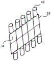
如在图12中示出,磷光体目标可以被像素化,每个像素布置成从在空间上位移的激光二极管40的阵列的其中一个接收光。然而,在可替换示例(如在图13中图示)中,磷光体可以不借助于在空间上分开的激光二极管被照射,而是可以反而由磷光体节段34的阵列组成,每个磷光体节段由集成的激光二极管48靠近泵浦。As shown in FIG. 12 , the phosphor target may be pixelated, with each pixel arranged to receive light from one of an array of spatially displaced
应当理解,尽管在上述示例中,操作于“透射模式”的磷光体目标(即,磷光体屏幕布置的表面区域)被提供或者示出,其中磷光体转换光从磷光体目标的与由激光源照射侧相对的那侧发射,本发明的实施例不限于这种配置。在可替换示例中,操作于“反射”模式的磷光体屏幕布置可以反而配置或者提供,其中磷光体转换光从磷光体目标的与由激光源照射侧相同的那侧发射。It will be appreciated that although in the above examples, a phosphor target operating in "transmissive mode" (ie, the surface area of the phosphor screen arrangement) is provided or shown, wherein the phosphor converts light from the phosphor target to and from the phosphor target and is generated by the laser source The side opposite the illumination side emits, and embodiments of the present invention are not limited to this configuration. In an alternative example, a phosphor screen arrangement operating in a "reflective" mode may be configured or provided instead, where the phosphor converted light is emitted from the same side of the phosphor target that is illuminated by the laser source.
本发明对于汽车前灯应用是特别令人感兴趣的。图14-17图示用于产生一系列不同输出前灯配置的系统实施例的示例应用。每个图示意性地描绘用于生成一反射输出分布的微显示器单元的像素配置,该反射输出分布适合用于产生具有具体束轮廓的前灯束。The present invention is of particular interest for automotive headlight applications. 14-17 illustrate example applications of system embodiments for producing a range of different output headlight configurations. Each figure schematically depicts the pixel configuration of a microdisplay unit used to generate a reflective output distribution suitable for use in generating a headlight beam with a specific beam profile.
图14示出第一示例微显示器配置,其用于交替产生近光前灯(其具有成角度的上截止)或者远光前灯。微显示器24是数字镜显示器(DMD),其包含反射器像素的阵列,每个反射器像素在高反射性(“接通”)模式和低反射性(“切断”)模式之间可切换。显示器的灰色经检查区域指示正在由磷光体布置的输出束图案照射但是其中像素切换至低反射性“切断”模式的区域。白色区域指示正在被照射并且其中像素切换至高反射性“接通”模式的区域。黑色经检查区域指示不正由磷光体屏幕布置照射的区域。14 shows a first example microdisplay configuration for alternately producing low beam headlights (with an angled upper cutoff) or high beam headlights.
在这个简单示例中,仅仅存在两个已建立区域,用于生成近光的第一52和用于生成远光的第二54。实线指示当束将从包含该系统的前灯单元被向前投射时,该束的形状。In this simple example, there are only two established regions, a first 52 for generating low beams and a second 54 for generating high beams. The solid line indicates the shape of the beam as it will be projected forward from the headlight unit containing the system.
当仅仅第一节段52接通时,则仅仅近光被产生。第一节段52的像素被配置以便产生近光前灯轮廓的特性成角度“扭结”—这个扭结设计成在一侧使束向下成角度,以便避免导致对在道路另一侧的迎面而来的交通工具的眩光。When only the
当仅仅近光将被生成时,系统被配置使得仅仅映射到微显示器的第一节段52上的磷光体屏幕布置(未示出)的表面区域由它的各自激光源照射,并且其余激光源被切断。以这种方式,通过不提供跨过第二节段的照射而节约显著能量,该第二节段在这个束模式中被配置以丢弃全部入射光。When only low beams are to be generated, the system is configured such that only the surface area of the phosphor screen arrangement (not shown) mapped onto the
系统另外允许近光的特定形状经由显示器而被动态地修改(见图14中的箭头)。例如,上截止线可以被向上/向下或者向左/向右移动,或者甚至重新成形,使得截止的角度变得例如更锐或者不那么锐。这些改变可以实时响应于某些驱动场景完成—例如响应于诸如急加速或者在隆起物上驾驶而提供上截止线的超快速调平。依赖于由分节段磷光体屏幕布置可实现的分辨率,这些调整也可以被伴有对磷光体屏幕布置的输出图案的调整。The system additionally allows the specific shape of the low beam to be dynamically modified via the display (see arrows in Figure 14). For example, the upper cutoff line may be moved up/down or left/right, or even reshaped so that the angle of the cutoff becomes, for example, sharper or less sharp. These changes can be done in real-time in response to certain driving scenarios—for example, in response to things such as hard acceleration or driving over bumps to provide ultra-fast leveling of the upper cutoff. Depending on the resolution achievable by the segmented phosphor screen arrangement, these adjustments may also be accompanied by adjustments to the output pattern of the phosphor screen arrangement.
注意,由此显示器24生成的近光输出可以不形成完整近光分布,而是例如可以仅仅形成完整近光分布的最中心部分。完整近光图案由于其大尺寸会难以仅仅由微显示器独自(以任何切实可行方式)创造,使得在切实可行的应用中,微显示器系统可以由一个或者多个LED照射单元补充,该LED照射单元配置成提供近光轮廓的外部延伸“翼”。Note that the low beam output generated by this
当远光将被生成时,微显示器的第一节段52和第二节段54两者被接通。在这种情况中,系统被配置使得映射到第一52和第二54节段上的磷光体屏幕布置的表面区域由它们各自激光源照射。When high beams are to be generated, both the
图15示意性地示出当配置用于这种远光模式的DMD。在这种示例中,通过将占据远光的上角落的像素切换至低反射性模式,DMD已经被用于剪掉所述角落(使图案为半梯形)。另外,靠近束中心的动态地可移动的暗区域56已经被创造(以允许防止对迎面而来的交通的眩光),并且更靠近束的侧边的相似暗区域58也被创造(以防止对迎面而来的道路标记的完整照射,这否则将导致对驾驶员本身的眩光)。Figure 15 schematically shows a DMD when configured for this high beam mode. In this example, DMD has been used to clip off the corners (making the pattern semi-trapezoid) by switching the pixels occupying the upper corners of the high beam to a low reflectivity mode. Additionally, a dynamically movable
在图16中图示第二示例微显示器配置,在这个情况中其用于仅仅产生远光,该远光具有动态地可调整的总宽度和/或横斜形状。示出的微显示器划分成四个不同照射节段60、62、64、66。显示器的经检查区域指示其中像素切换至低反射性“切断”模式的区域,而白色或者灰色区域指示其中像素切换至高反射性“接通”模式的区域。A second example microdisplay configuration is illustrated in FIG. 16, which in this case is used to generate only the high beam with a dynamically adjustable overall width and/or cross-beam shape. The microdisplay shown is divided into four
另外,白色区域特别地指示正在由磷光体屏幕布置用完整强度光照射的区域,而灰色区域指示正由磷光体屏幕布置用半强度光照射的区域。此实施例需要照射磷光体屏幕布置的表面区域的激光源被配置成产生可变强度的光,使得依赖于跨过微显示器的期望强度分布,提供至磷光体表面区域的光的强度可以被修改。In addition, white areas specifically indicate areas that are being illuminated with full intensity light by the phosphor screen arrangement, while grey areas indicate areas that are being illuminated with half intensity light by the phosphor screen arrangement. This embodiment requires that the laser source illuminating the surface area of the phosphor screen arrangement be configured to generate light of variable intensity, so that the intensity of the light provided to the phosphor surface area can be modified depending on the desired intensity distribution across the microdisplay .
在图16中示出其中全部四个节段接通的配置。第二62和第三64节段正在用完整强度光照射(以为束图案提供亮中心),而第一60和第四66节段正在用仅仅半强度光照射以为束图案提供渐缩外部边缘。另外,左上角落经由DMD已经被修圆。另外,如在前文示例中那样,DMD配置成产生两个可移动暗区域56、58。A configuration in which all four segments are turned on is shown in FIG. 16 . The second 62 and third 64 segments are being illuminated with full intensity light (to provide a bright center for the beam pattern), while the first 60 and fourth 66 segments are illuminated with only half intensity light to provide tapered outer edges for the beam pattern. Also, the top left drop has been rounded via DMD. Additionally, as in the previous example, the DMD is configured to generate two movable
图17示出图16的配置,但是其中照明图案已经响应于改变的道路条件(例如,道路向左急弯)被重新配置。束的左边需要更多强度,并且因此第一节段60被切换至完整强度,而节段三64切换至半强度。节段四66甚至进一步被调光。结果是,整个远光图案向左偏移。FIG. 17 shows the configuration of FIG. 16 , but in which the lighting pattern has been reconfigured in response to changing road conditions (eg, the road turns sharply to the left). The left side of the beam requires more intensity, and so the
注意,在可替换示例中,不是通过改变提供至各自磷光体表面区域的光的强度,而是反而通过提供具有能够在一系列不同反射性模式之间切换的像素的DMD,可以创造跨过显示器24的不同节段的照射的不同强度。在这个情况中,均匀水平的光可以被提供至将至少反射一些光的显示器的每个节段,并且不同输出强度可以通过选择性地控制对应像素的反射性水平而生成。Note that, in an alternative example, rather than varying the intensity of the light provided to the respective phosphor surface areas, but rather by providing a DMD with pixels capable of switching between a series of different reflectivity modes, it is possible to create a bridge across the
在这个情况中,照射分段的不同强度水平将不创造输出图案中的突然台阶,因为DMD的强度调谐可以用于“平滑”相邻节段之间的强度改变。In this case, different intensity levels of the illuminated segments will not create abrupt steps in the output pattern, as the intensity tuning of the DMD can be used to "smooth" intensity changes between adjacent segments.
另外注意,微显示器的照射分段在示例中可以重叠。然而这种重叠可以通过对DMD的适当控制补偿:由任何这种重叠导致的多余亮度可以通过仅仅调整对应显示器像素的反射性强度而被“修复”或者移除。Also note that the illumination segments of the microdisplay may overlap in the example. However, this overlap can be compensated for by appropriate control of the DMD: the excess brightness caused by any such overlap can be "fixed" or removed by simply adjusting the reflective intensity of the corresponding display pixel.
尽管本发明的实施例的应用已经特别地关于汽车前灯被描述,应当理解,本发明对将激光器光(例如,蓝色)与磷光体波长转换组合的任何其他微显示器投射应用具有更通常的应用性。Although the application of embodiments of the present invention has been described in particular with respect to automotive headlights, it should be understood that the present invention has more general application to any other microdisplay projection application that combines laser light (eg, blue) with phosphor wavelength conversion applicability.
通过研究附图、公开文本和所附权利要求,本领域技术人员在实践所要求保护的发明时可以理解和达成所公开实施例的其他变型。在权利要求中,词语“包含”不排除其他元件或者步骤,并且不定冠词“一(a或者an)”不排除多个。某些措施被叙述于相互不同从属权利要求中的纯粹事实不表明这些措施的组合不能被有利地使用。权利要求中的任何附图标记不应当被解释为限制范围。Other modifications to the disclosed embodiments can be understood and effected by those skilled in the art in practicing the claimed invention, from a study of the drawings, the disclosure, and the appended claims. In the claims, the word "comprising" does not exclude other elements or steps, and the indefinite article "a (a or an)" does not exclude a plurality. The mere fact that certain measures are recited in mutually different dependent claims does not indicate that a combination of these measures cannot be used to advantage. Any reference signs in the claims should not be construed as limiting the scope.
Claims (15)
Applications Claiming Priority (3)
| Application Number | Priority Date | Filing Date | Title |
|---|---|---|---|
| EP15183291 | 2015-09-01 | ||
| EP15183291.2 | 2015-09-01 | ||
| PCT/EP2016/069930 WO2017036871A1 (en) | 2015-09-01 | 2016-08-24 | A lighting system and a lighting method |
Publications (2)
| Publication Number | Publication Date |
|---|---|
| CN107923602A CN107923602A (en) | 2018-04-17 |
| CN107923602B true CN107923602B (en) | 2020-02-07 |
Family
ID=54072675
Family Applications (1)
| Application Number | Title | Priority Date | Filing Date |
|---|---|---|---|
| CN201680050796.9A Active CN107923602B (en) | 2015-09-01 | 2016-08-24 | Illumination system and illumination method |
Country Status (5)
| Country | Link |
|---|---|
| US (1) | US20180259156A1 (en) |
| EP (1) | EP3344919B1 (en) |
| JP (1) | JP6745335B2 (en) |
| CN (1) | CN107923602B (en) |
| WO (1) | WO2017036871A1 (en) |
Families Citing this family (13)
| Publication number | Priority date | Publication date | Assignee | Title |
|---|---|---|---|---|
| US10180224B2 (en) | 2016-07-26 | 2019-01-15 | Texas Instruments Incorporated | Quasi-sparse optical illumination |
| FR3056680B1 (en) * | 2016-09-29 | 2018-11-09 | Valeo Vision | LIGHTING SYSTEM FOR MOTOR VEHICLE |
| US10596952B2 (en) * | 2017-09-13 | 2020-03-24 | Shanghai Koito Automotive Lamp Co., Ltd. | Intelligent lighting system for automobile lamp, automobile lamp assembly and automobile |
| DE102017217164B4 (en) * | 2017-09-27 | 2020-10-15 | Continental Automotive Gmbh | Projection device for generating a pixel-based lighting pattern |
| CN108826215A (en) * | 2018-07-26 | 2018-11-16 | 华域视觉科技(上海)有限公司 | Special-shaped illuminator and special-shaped luminescence unit |
| WO2020020690A1 (en) * | 2018-07-27 | 2020-01-30 | Lumileds Holding B.V. | Illumination device for a vehicle headlamp |
| WO2020051276A1 (en) | 2018-09-05 | 2020-03-12 | Flex-N-Gate Advanced Product Development, Llc | Programmable glare-free high beam |
| DE102019106674A1 (en) | 2019-03-15 | 2020-09-17 | OSRAM Opto Semiconductors Gesellschaft mit beschränkter Haftung | Device and method for projecting a plurality of focal points onto a surface |
| US11703747B2 (en) * | 2020-12-01 | 2023-07-18 | Texas Instruments Incorporated | Solid state illumination for optical projector using static phosphors |
| WO2023039590A1 (en) | 2021-09-13 | 2023-03-16 | Blue Vigil Llc | Systems and methods for tethered drones |
| CN114839831B (en) * | 2022-03-17 | 2024-07-05 | 上海晶合光电科技有限公司 | LED matrix floor projection module |
| US12449106B2 (en) | 2022-09-23 | 2025-10-21 | Autosystems, A Division Of Magna Exteriors Inc. | Vehicle headlight assembly and system with hybrid matrix low beam |
| DE102022130786B4 (en) * | 2022-11-22 | 2024-07-25 | Marelli Automotive Lighting Reutlingen (Germany) GmbH | Lighting device for a motor vehicle |
Citations (6)
| Publication number | Priority date | Publication date | Assignee | Title |
|---|---|---|---|---|
| CN100387461C (en) * | 2001-12-10 | 2008-05-14 | 金泰克斯公司 | Anti-glare headlight control |
| CN101516676B (en) * | 2006-09-21 | 2012-11-28 | 皇家飞利浦电子股份有限公司 | A car light, a method of adjusting a car light, and a car with a car light |
| CN103574473A (en) * | 2012-07-27 | 2014-02-12 | 法雷奥照明公司 | Adaptive lighting system for an automobile |
| CN104100909A (en) * | 2014-08-04 | 2014-10-15 | 安徽师范大学 | Design method of self-adaptive headlamp based on fly's-eye lens |
| CN104728734A (en) * | 2013-12-19 | 2015-06-24 | 欧司朗股份有限公司 | Generating Light Emission Pattern In Far Field |
| CN104848134A (en) * | 2010-05-12 | 2015-08-19 | 欧司朗有限公司 | Headlight module |
Family Cites Families (10)
| Publication number | Priority date | Publication date | Assignee | Title |
|---|---|---|---|---|
| US6781691B2 (en) * | 2001-02-02 | 2004-08-24 | Tidal Photonics, Inc. | Apparatus and methods relating to wavelength conditioning of illumination |
| US6497503B1 (en) * | 2001-06-21 | 2002-12-24 | Ford Global Technologies, Inc. | Headlamp system with selectable beam pattern |
| EP1485904B1 (en) * | 2002-03-13 | 2012-08-29 | Dolby Laboratories Licensing Corporation | High dynamic range display devices |
| US20070115440A1 (en) * | 2005-11-21 | 2007-05-24 | Microvision, Inc. | Projection display with screen compensation |
| GB2497949A (en) * | 2011-12-22 | 2013-07-03 | Sharp Kk | Headlight system with adaptive beam function |
| GB2497950A (en) * | 2011-12-22 | 2013-07-03 | Sharp Kk | Laser and Phosphor Based Light Source for Improved Safety |
| US9534756B2 (en) * | 2012-04-03 | 2017-01-03 | Sharp Kabushiki Kaisha | Light-emitting device, floodlight, and vehicle headlight |
| CN104412035B (en) * | 2012-06-29 | 2016-10-19 | 株式会社小糸制作所 | Lamps apparatus for vehicle and control method thereof |
| JP6361333B2 (en) * | 2013-07-31 | 2018-07-25 | 日亜化学工業株式会社 | Light source device and optical engine |
| US9412336B2 (en) * | 2013-10-07 | 2016-08-09 | Google Inc. | Dynamic backlight control for spatially independent display regions |
-
2016
- 2016-08-24 CN CN201680050796.9A patent/CN107923602B/en active Active
- 2016-08-24 JP JP2018510706A patent/JP6745335B2/en active Active
- 2016-08-24 WO PCT/EP2016/069930 patent/WO2017036871A1/en not_active Ceased
- 2016-08-24 EP EP16760007.1A patent/EP3344919B1/en active Active
- 2016-08-24 US US15/756,459 patent/US20180259156A1/en not_active Abandoned
Patent Citations (6)
| Publication number | Priority date | Publication date | Assignee | Title |
|---|---|---|---|---|
| CN100387461C (en) * | 2001-12-10 | 2008-05-14 | 金泰克斯公司 | Anti-glare headlight control |
| CN101516676B (en) * | 2006-09-21 | 2012-11-28 | 皇家飞利浦电子股份有限公司 | A car light, a method of adjusting a car light, and a car with a car light |
| CN104848134A (en) * | 2010-05-12 | 2015-08-19 | 欧司朗有限公司 | Headlight module |
| CN103574473A (en) * | 2012-07-27 | 2014-02-12 | 法雷奥照明公司 | Adaptive lighting system for an automobile |
| CN104728734A (en) * | 2013-12-19 | 2015-06-24 | 欧司朗股份有限公司 | Generating Light Emission Pattern In Far Field |
| CN104100909A (en) * | 2014-08-04 | 2014-10-15 | 安徽师范大学 | Design method of self-adaptive headlamp based on fly's-eye lens |
Also Published As
| Publication number | Publication date |
|---|---|
| EP3344919B1 (en) | 2019-10-09 |
| WO2017036871A1 (en) | 2017-03-09 |
| JP2018528582A (en) | 2018-09-27 |
| JP6745335B2 (en) | 2020-08-26 |
| US20180259156A1 (en) | 2018-09-13 |
| CN107923602A (en) | 2018-04-17 |
| EP3344919A1 (en) | 2018-07-11 |
Similar Documents
| Publication | Publication Date | Title |
|---|---|---|
| CN107923602B (en) | Illumination system and illumination method | |
| US10753566B2 (en) | Methods and apparatus for illumination with laser modulated adaptive beam shaping | |
| US11391428B2 (en) | Pixelated projection for automotive headlamp | |
| US9777901B2 (en) | Headlight for a motor vehicle and method for distributing light | |
| JP6212218B2 (en) | Lighting device | |
| CN114974010B (en) | Headlight device | |
| JP6530514B2 (en) | Headlights for vehicles | |
| CN111356876A (en) | Light modules for motor vehicle headlights | |
| CN107076388A (en) | Searchlighting lamp module with beam steering apparatus and luminescent substance | |
| CN108291704B (en) | Beam projection devices including digital screens and headlamps equipped with such devices | |
| JP6499313B2 (en) | Automotive lighting system | |
| JP6936646B2 (en) | Vehicle lighting | |
| CN110573796A (en) | Device and method for producing output light emission and headlamp | |
| KR20190111798A (en) | Illumination device for a motor vehicle headlight | |
| CN103867985A (en) | Motor vehicle headlamp with a dazzle-free main beam | |
| CN111505749B (en) | Lens array and illumination optical device | |
| JP2019102380A (en) | Vehicular lighting fixture system | |
| CN112097214A (en) | Lamp unit and vehicle headlamp | |
| JP7042655B2 (en) | Vehicle lighting | |
| CN109539170B (en) | Lighting devices, automobile headlights and lighting systems | |
| KR20210081560A (en) | Head lamp for vehicle | |
| JP2020126215A (en) | Lens array and illumination optical device |
Legal Events
| Date | Code | Title | Description |
|---|---|---|---|
| PB01 | Publication | ||
| PB01 | Publication | ||
| SE01 | Entry into force of request for substantive examination | ||
| SE01 | Entry into force of request for substantive examination | ||
| GR01 | Patent grant | ||
| GR01 | Patent grant |