CN107852449B - Vibrating device and camera - Google Patents
Vibrating device and camera Download PDFInfo
- Publication number
- CN107852449B CN107852449B CN201680040944.9A CN201680040944A CN107852449B CN 107852449 B CN107852449 B CN 107852449B CN 201680040944 A CN201680040944 A CN 201680040944A CN 107852449 B CN107852449 B CN 107852449B
- Authority
- CN
- China
- Prior art keywords
- cylindrical
- vibration
- mode
- body portion
- mode conversion
- Prior art date
- Legal status (The legal status is an assumption and is not a legal conclusion. Google has not performed a legal analysis and makes no representation as to the accuracy of the status listed.)
- Active
Links
Images





Classifications
-
- G—PHYSICS
- G02—OPTICS
- G02B—OPTICAL ELEMENTS, SYSTEMS OR APPARATUS
- G02B27/00—Optical systems or apparatus not provided for by any of the groups G02B1/00 - G02B26/00, G02B30/00
- G02B27/0006—Optical systems or apparatus not provided for by any of the groups G02B1/00 - G02B26/00, G02B30/00 with means to keep optical surfaces clean, e.g. by preventing or removing dirt, stains, contamination, condensation
-
- B—PERFORMING OPERATIONS; TRANSPORTING
- B06—GENERATING OR TRANSMITTING MECHANICAL VIBRATIONS IN GENERAL
- B06B—METHODS OR APPARATUS FOR GENERATING OR TRANSMITTING MECHANICAL VIBRATIONS OF INFRASONIC, SONIC, OR ULTRASONIC FREQUENCY, e.g. FOR PERFORMING MECHANICAL WORK IN GENERAL
- B06B3/00—Methods or apparatus specially adapted for transmitting mechanical vibrations of infrasonic, sonic, or ultrasonic frequency
-
- B—PERFORMING OPERATIONS; TRANSPORTING
- B06—GENERATING OR TRANSMITTING MECHANICAL VIBRATIONS IN GENERAL
- B06B—METHODS OR APPARATUS FOR GENERATING OR TRANSMITTING MECHANICAL VIBRATIONS OF INFRASONIC, SONIC, OR ULTRASONIC FREQUENCY, e.g. FOR PERFORMING MECHANICAL WORK IN GENERAL
- B06B3/00—Methods or apparatus specially adapted for transmitting mechanical vibrations of infrasonic, sonic, or ultrasonic frequency
- B06B3/02—Methods or apparatus specially adapted for transmitting mechanical vibrations of infrasonic, sonic, or ultrasonic frequency involving a change of amplitude
-
- G—PHYSICS
- G03—PHOTOGRAPHY; CINEMATOGRAPHY; ANALOGOUS TECHNIQUES USING WAVES OTHER THAN OPTICAL WAVES; ELECTROGRAPHY; HOLOGRAPHY
- G03B—APPARATUS OR ARRANGEMENTS FOR TAKING PHOTOGRAPHS OR FOR PROJECTING OR VIEWING THEM; APPARATUS OR ARRANGEMENTS EMPLOYING ANALOGOUS TECHNIQUES USING WAVES OTHER THAN OPTICAL WAVES; ACCESSORIES THEREFOR
- G03B17/00—Details of cameras or camera bodies; Accessories therefor
- G03B17/02—Bodies
-
- G—PHYSICS
- G03—PHOTOGRAPHY; CINEMATOGRAPHY; ANALOGOUS TECHNIQUES USING WAVES OTHER THAN OPTICAL WAVES; ELECTROGRAPHY; HOLOGRAPHY
- G03B—APPARATUS OR ARRANGEMENTS FOR TAKING PHOTOGRAPHS OR FOR PROJECTING OR VIEWING THEM; APPARATUS OR ARRANGEMENTS EMPLOYING ANALOGOUS TECHNIQUES USING WAVES OTHER THAN OPTICAL WAVES; ACCESSORIES THEREFOR
- G03B17/00—Details of cameras or camera bodies; Accessories therefor
- G03B17/56—Accessories
-
- B—PERFORMING OPERATIONS; TRANSPORTING
- B06—GENERATING OR TRANSMITTING MECHANICAL VIBRATIONS IN GENERAL
- B06B—METHODS OR APPARATUS FOR GENERATING OR TRANSMITTING MECHANICAL VIBRATIONS OF INFRASONIC, SONIC, OR ULTRASONIC FREQUENCY, e.g. FOR PERFORMING MECHANICAL WORK IN GENERAL
- B06B1/00—Methods or apparatus for generating mechanical vibrations of infrasonic, sonic, or ultrasonic frequency
- B06B1/02—Methods or apparatus for generating mechanical vibrations of infrasonic, sonic, or ultrasonic frequency making use of electrical energy
- B06B1/06—Methods or apparatus for generating mechanical vibrations of infrasonic, sonic, or ultrasonic frequency making use of electrical energy operating with piezoelectric effect or with electrostriction
-
- G—PHYSICS
- G03—PHOTOGRAPHY; CINEMATOGRAPHY; ANALOGOUS TECHNIQUES USING WAVES OTHER THAN OPTICAL WAVES; ELECTROGRAPHY; HOLOGRAPHY
- G03B—APPARATUS OR ARRANGEMENTS FOR TAKING PHOTOGRAPHS OR FOR PROJECTING OR VIEWING THEM; APPARATUS OR ARRANGEMENTS EMPLOYING ANALOGOUS TECHNIQUES USING WAVES OTHER THAN OPTICAL WAVES; ACCESSORIES THEREFOR
- G03B17/00—Details of cameras or camera bodies; Accessories therefor
- G03B17/02—Bodies
- G03B17/08—Waterproof bodies or housings
-
- H—ELECTRICITY
- H04—ELECTRIC COMMUNICATION TECHNIQUE
- H04N—PICTORIAL COMMUNICATION, e.g. TELEVISION
- H04N23/00—Cameras or camera modules comprising electronic image sensors; Control thereof
- H04N23/50—Constructional details
- H04N23/51—Housings
Landscapes
- Physics & Mathematics (AREA)
- General Physics & Mathematics (AREA)
- Engineering & Computer Science (AREA)
- Mechanical Engineering (AREA)
- Optics & Photonics (AREA)
- Accessories Of Cameras (AREA)
- Studio Devices (AREA)
- General Electrical Machinery Utilizing Piezoelectricity, Electrostriction Or Magnetostriction (AREA)
- Lens Barrels (AREA)
- Camera Bodies And Camera Details Or Accessories (AREA)
- Piezo-Electric Transducers For Audible Bands (AREA)
Abstract
Description
技术领域technical field
本发明涉及具有透镜的摄像头主体中所使用的振动装置、以及摄像头。The present invention relates to a vibration device used in a camera body having a lens, and a camera.
背景技术Background technique
车辆搭载用摄像头、设置于屋外的摄像头暴露在雨中。因此,在镜头前方设有由玻璃、透明塑料构成的外罩。然而,若在该外罩附着水滴,摄像头的视野则变得不清晰。并且无法正确地拍摄图像。Vehicle-mounted cameras and cameras installed outdoors were exposed to rain. Therefore, a cover made of glass or transparent plastic is provided in front of the lens. However, when water droplets adhere to the cover, the field of view of the camera becomes unclear. and the image cannot be taken properly.
下述专利文献1中,公开了用于这种用途的圆顶型外罩。该圆顶型外罩与圆筒部连结,在圆筒部安装压电陶瓷振子。通过使压电陶瓷振子振动,使圆筒部以及圆顶型外罩振动。由此去除附着在圆顶型外罩的表面的水滴。The following
另一方面,在下述专利文献2中,公开了在摄像头主体的前方配置超声换能器、粘接材料层以及外部镜头的结构。通过驱动超声换能器,来使外部镜头振动。由此去除水滴。On the other hand, the following
现有技术文献prior art literature
专利文献Patent Literature
专利文献1:日本专利特开2012-138768号公报Patent Document 1: Japanese Patent Laid-Open No. 2012-138768
专利文献2:日本专利特开2007-82062号公报Patent Document 2: Japanese Patent Laid-Open No. 2007-82062
发明内容SUMMARY OF THE INVENTION
发明所要解决的技术问题The technical problem to be solved by the invention
专利文献1、专利文献2中,去除水滴需要使圆顶型外罩、外部镜头较大地振动。即,专利文献1、专利文献2的结构中,在压电陶瓷振子、超声换能器中需要产生较大的振动。因此,对压电陶瓷振子、超声换能器施加较大的应力,从而在使用过程中,可能在压电陶瓷振子、超声换能器中产生裂纹,引起功能不全。此外除了水滴,还要求去除乙醇等水以外的溶液、溶解了盐、防冻液(氯化钠)等的水溶液、泥水等在水中含有未溶解的杂质的液滴、或咖啡等胶体(colloid)溶液等。In
本发明的目的在于提供一种振动装置以及具有该振动装置的摄像头,该振动装置能不对压电振子施加较大负荷,有利地去除附着在外罩、镜头上的水滴等。The object of the present invention is to provide a vibrating device and a camera having the vibrating device, which can advantageously remove water droplets and the like adhering to the housing and the lens without applying a large load to the piezoelectric vibrator.
解决技术问题的技术方案technical solutions to technical problems
由本发明的某一广泛方面所提供的振动装置被用于具有透镜的摄像头主体,该振动装置包括:筒状振动体部,该筒状振动体部具有筒状构件、以及固定于所述筒状构件的压电振子;模式转换结合部,该筒状的模式转换结合部与所述筒状振动体部的一端连结;以及透光体部,该透光体部与所述模式转换结合部的、连结所述筒状振动体部的一侧的相反侧接合,具有配置于所述透镜的前方的透光性部分,所述模式转换结合部具有与所述筒状振动体部相比、厚度较薄的薄壁部。A vibrating device provided by a broad aspect of the present invention is used for a camera body having a lens, the vibrating device including: a cylindrical vibrating body portion having a cylindrical member, and a cylindrical vibrating body portion fixed to the cylindrical body The piezoelectric vibrator of the component; a mode conversion joint part, the cylindrical mode conversion joint part is connected to one end of the cylindrical vibrating body part; , the joint opposite to the side connecting the cylindrical vibrating body part has a light-transmitting part arranged in front of the lens, and the mode conversion coupling part has a thickness greater than that of the cylindrical vibrating body part Thinner thin-walled portion.
由本发明的另一广泛方面所提供的振动装置被用于具有透镜的摄像头主体,该振动装置包括:筒状振动体部,该筒状振动体部具有筒状构件、以及固定于所述筒状构件的压电振子;筒状的模式转换结合部,该模式转换结合部与所述筒状振动体部的一端连结,在与该筒状振动体部的一端连结的一侧的相反侧与摄像头的所述透镜接合,所述模式转换结合部具有与所述筒状振动体部相比、厚度较薄的薄壁部。A vibrating device provided by another broad aspect of the present invention is used for a camera body having a lens, the vibrating device comprising: a cylindrical vibrating body portion having a cylindrical member, and a cylindrical vibrating body portion fixed to the cylindrical body A piezoelectric vibrator of a component; a cylindrical mode conversion coupling portion connected to one end of the cylindrical vibrating body portion, and a camera head on the opposite side of the side connected to the one end of the cylindrical vibrating body portion The lens-bonded part has a thin-walled part thinner than that of the cylindrical vibrating body part.
本发明涉及的振动装置的某一特定方面中,所述模式转换结合部构成为将所述筒状振动体部中的振动模式转换为所述透光体部的振动模式,并且使振动增大。In a specific aspect of the vibration device according to the present invention, the mode conversion coupling portion is configured to convert a vibration mode in the cylindrical vibrating body portion into a vibration mode of the light-transmitting body portion and increase vibration .
本发明涉及的振动装置的某一特定方面中,所述模式转换结合部的体积比所述筒状振动体部的体积小。该情况下,能使筒状振动体部的振动在模式转换结合部中进一步扩大。In a specific aspect of the vibrating device according to the present invention, the volume of the mode conversion coupling portion is smaller than the volume of the cylindrical vibrating body portion. In this case, the vibration of the cylindrical vibrating body portion can be further expanded in the mode conversion joint portion.
本发明涉及的振动装置的另一特定的方面中,所述压电振子为筒状。In another specific aspect of the vibration device according to the present invention, the piezoelectric vibrator has a cylindrical shape.
本发明涉及的振动装置的另一特定的方面中,所述透光体部中所述振动模式的谐振频率、和所述筒状振动体部中纵向效应或横向效应的的振动模式的谐振频率大致一致。在该情况下,能更有效的实现振动模式的转换和振动的扩大。In another specific aspect of the vibration device according to the present invention, the resonance frequency of the vibration mode in the light-transmitting body portion and the resonance frequency of the vibration mode of the longitudinal effect or the lateral effect in the cylindrical vibration body portion roughly the same. In this case, the conversion of the vibration mode and the expansion of the vibration can be realized more effectively.
本发明涉及的振动装置的另一特定的方面中,所述透镜中所述振动模式的谐振频率、和所述筒状振动体部中纵向效应或横向效应的振动模式的谐振频率大致一致。In another specific aspect of the vibrating device according to the present invention, the resonance frequency of the vibration mode in the lens is substantially the same as the resonance frequency of the vibration mode of the longitudinal effect or the lateral effect in the cylindrical vibrating body portion.
本发明涉及的振动装置的另一特定的方面中,在所述筒状振动体部的所述模式转换结合部侧的端部设有向外侧延伸的凸缘部。优选地,所述筒状振动体部的振动的节点存在于所述凸缘部。在该情况下,由于能减少振动向外部的泄漏,因此在模式转换结合部中,能更有效地扩大振动。In another specific aspect of the vibrating device according to the present invention, a flange portion extending outward is provided at an end portion of the cylindrical vibrating body portion on the mode conversion coupling portion side. Preferably, a node of vibration of the cylindrical vibrating body portion is present in the flange portion. In this case, since the leakage of the vibration to the outside can be reduced, the vibration can be amplified more effectively in the mode conversion joint portion.
本发明所涉及的振动装置的又一特定的方面中,所述筒状振动体部为圆筒状。但是在本发明中,筒状振动体部也可以是方筒状。In yet another specific aspect of the vibrating device according to the present invention, the cylindrical vibrating body portion has a cylindrical shape. However, in the present invention, the cylindrical vibrating body portion may have a rectangular cylindrical shape.
本发明所涉及的振动装置的另一特定的方面中,所述模式转换结合部为圆筒状。在该情况下,能有利地将模式转换结合部与圆顶状、圆盘状的透光体部连结。In another specific aspect of the vibration device according to the present invention, the mode conversion coupling portion is cylindrical. In this case, the mode conversion joint portion can be advantageously connected to the dome-shaped or disk-shaped light-transmitting body portion.
本发明涉及的振动装置的另一特定的方面中,所述透光体部是具有配置于所述透镜的前方的曲面状透光性部分的圆顶状。在该情况下,能容易地将设有摄像头主体的透镜的部分收纳在圆顶状的形状内并且能实现广角视野。In another specific aspect of the vibrating device according to the present invention, the light-transmitting body portion has a dome shape having a curved light-transmitting portion disposed in front of the lens. In this case, the portion where the lens of the camera body is provided can be easily accommodated in the dome-like shape, and a wide-angle field of view can be realized.
本发明涉及的振动装置的另一特定的方面中,所述圆顶状的所述透光体部中的振动模式为呼吸振动模式。In another specific aspect of the vibration device according to the present invention, the vibration mode in the dome-shaped light-transmitting body portion is a breathing vibration mode.
本发明涉及的振动装置的又一特定的方面中,所述圆顶状的所述透光体部中的振动模式为弯曲振动模式。In yet another specific aspect of the vibration device according to the present invention, the vibration mode in the dome-shaped light-transmitting body portion is a bending vibration mode.
本发明涉及的振动装置的另一特定的方面中,所述透镜的振动模式为呼吸振动模式。In another specific aspect of the vibration device according to the present invention, the vibration mode of the lens is a breathing vibration mode.
本发明涉及的振动装置的另一特定的方面中,所述透镜的振动模式为弯曲振动模式。In another specific aspect of the vibration device according to the present invention, the vibration mode of the lens is a bending vibration mode.
本发明涉及的振动装置的又一特定的方面中,所述模式转换结合部由具有与所述筒状振动体部的外径相同的外径的筒状体构成。In yet another specific aspect of the vibrating device according to the present invention, the mode conversion coupling portion is constituted by a cylindrical body having the same outer diameter as the outer diameter of the cylindrical vibrating body portion.
本发明涉及的振动装置的又一特定的方面中,所述模式转换结合部由比所述筒状振动体部细的筒状体构成。In still another specific aspect of the vibrating device according to the present invention, the mode conversion coupling portion is formed of a cylindrical body thinner than the cylindrical vibrating body portion.
本发明涉及的振动装置的另一特定的方面中,所述模式转换结合部的外径或内径中的至少一方随着从所述筒状振动体部侧的端部向所述透光体部侧而连续地变化。In another specific aspect of the vibrating device according to the present invention, at least one of an outer diameter or an inner diameter of the mode conversion coupling portion is directed from the end portion on the side of the cylindrical vibrating body portion to the translucent body portion. change continuously.
本发明涉及的振动装置的又一特定的方面中,在所述模式转换结合部的所述透光体部侧的端部,设有朝向筒状体的中心侧或筒状体的外侧的凸缘部。In still another specific aspect of the vibrating device according to the present invention, a protrusion facing a center side of the cylindrical body or an outer side of the cylindrical body is provided at an end portion of the mode conversion coupling portion on the light-transmitting body portion side. edge.
本发明涉及的摄像头包括:依照本发明而构成的振动装置;以及在所述振动装置内至少收纳了一部分的摄像头主体。The camera according to the present invention includes: a vibration device constructed according to the present invention; and a camera body that accommodates at least a part of the vibration device.
发明效果Invention effect
根据本发明涉及的振动装置,能不对压电振子施加较大负荷,而通过模式转换结合部进行的振动模式的转换以及振动的扩大作用,使透光体部、透镜较大地振动。从而,能有利地去除附着在透光体部、透镜上的水滴。According to the vibrating device according to the present invention, the light-transmitting body and the lens can be greatly vibrated by the conversion of the vibration mode by the mode conversion coupling portion and the amplification of the vibration without applying a large load to the piezoelectric vibrator. Therefore, the water droplets adhering to the light-transmitting body and the lens can be favorably removed.
附图说明Description of drawings
图1是本发明的第一实施方式涉及的摄像头的简图的正面剖视图。FIG. 1 is a schematic front cross-sectional view of a camera according to a first embodiment of the present invention.
图2是本发明的第一实施方式中所使用的振动装置的立体图。FIG. 2 is a perspective view of the vibration device used in the first embodiment of the present invention.
图3是本发明的第一实施方式中所使用的压电振子的正面剖视图。3 is a front cross-sectional view of the piezoelectric vibrator used in the first embodiment of the present invention.
图4是表示本发明的第一实施方式中谐振特性与透光体部的顶点的位移量的关系的图。4 is a diagram showing the relationship between the resonance characteristics and the displacement amount of the vertex of the light-transmitting body portion in the first embodiment of the present invention.
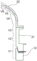
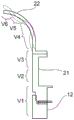
图5是用于说明由图4的箭头A所示的位移量的情况下振动装置的位移状态的示意图。FIG. 5 is a schematic diagram for explaining the displacement state of the vibration device in the case of the displacement amount indicated by the arrow A in FIG. 4 .
图6是用于说明由图4的箭头B所示的位移量的情况下振动装置的位移状态的示意图。FIG. 6 is a schematic diagram for explaining the displacement state of the vibration device in the case of the displacement amount indicated by the arrow B in FIG. 4 .
图7是用于说明由图4的箭头C所示的位移量的情况下振动装置的位移状态的示意图。FIG. 7 is a schematic diagram for explaining the displacement state of the vibration device in the case of the displacement amount indicated by the arrow C in FIG. 4 .
图8是用于说明由图4的箭头D所示的位移量的情况下振动装置的位移状态的示意图。FIG. 8 is a schematic diagram for explaining the displacement state of the vibration device in the case of the displacement amount indicated by the arrow D in FIG. 4 .
图9是用于说明由图4的箭头E所示的位移量的情况下振动装置的位移状态的示意图。FIG. 9 is a schematic diagram for explaining the displacement state of the vibration device in the case of the displacement amount indicated by the arrow E in FIG. 4 .
图10是用于说明由图4的箭头F所示的位移量的情况下振动装置的位移状态的示意图。FIG. 10 is a schematic diagram for explaining the displacement state of the vibrating device in the case of the displacement amount indicated by the arrow F in FIG. 4 .
图11是用于说明筒状振动体部的变形例的立体图。FIG. 11 is a perspective view for explaining a modification of the cylindrical vibrating body portion.
图12是用于说明筒状振动体部的另一变形例的立体图。12 is a perspective view for explaining another modification of the cylindrical vibrating body portion.
图13是用于说明本发明的第二实施方式涉及的振动装置中、筒状振动体部和模式转换结合部的立体图。13 is a perspective view for explaining a cylindrical vibrating body portion and a mode conversion coupling portion in the vibrating device according to the second embodiment of the present invention.
图14(a)和图14(b)是表示针对本发明中筒状振动体部和模式转换结合部的组合的第一以及第二变形例的简图的正面剖视图。FIGS. 14( a ) and 14 ( b ) are front cross-sectional views showing schematic diagrams of first and second modified examples of the combination of the cylindrical vibrating body portion and the mode conversion coupling portion in the present invention.
图15(a)和图15(b)是表示针对本发明中筒状振动体部和模式转换结合部的组合的第三以及第四变形例的简图的正面剖视图。FIGS. 15( a ) and 15 ( b ) are front cross-sectional views showing schematic diagrams of third and fourth modified examples of the combination of the cylindrical vibrating body portion and the mode conversion coupling portion in the present invention.
图16(a)和图16(b)是表示针对本发明中筒状振动体部和模式转换结合部的组合的第五以及第六变形例的简图的正面剖视图。FIGS. 16( a ) and 16 ( b ) are front cross-sectional views showing schematic diagrams of fifth and sixth modified examples of the combination of the cylindrical vibrating body portion and the mode conversion coupling portion in the present invention.
图17(a)和图17(b)是表示针对本发明中筒状振动体部和模式转换结合部的组合的第七以及第八变形例的简图的正面剖视图。FIGS. 17( a ) and 17 ( b ) are front cross-sectional views showing schematic diagrams of seventh and eighth modified examples of the combination of the cylindrical vibrating body portion and the mode conversion coupling portion in the present invention.
图18是第三实施方式涉及的摄像头的正面剖视图。18 is a front cross-sectional view of a camera according to a third embodiment.
图19是第三实施方式的变形例涉及的摄像头的正面剖视图。19 is a front cross-sectional view of a camera according to a modification of the third embodiment.
图20是本发明的第四实施方式涉及的摄像头的正面剖视图。20 is a front cross-sectional view of a camera according to a fourth embodiment of the present invention.
具体实施方式Detailed ways
下面,参照附图,对本发明的具体的实施方式进行说明,从而明确本发明。Hereinafter, the present invention will be clarified by describing specific embodiments of the present invention with reference to the accompanying drawings.
此外,本说明书中记载的各实施方式是例示,这里先指出在不同的实施方式间,能进行结构的部分置换或组合。In addition, each embodiment described in this specification is an illustration, and it is pointed out here that a part of a structure can be replaced or combined among different embodiments.
图1是本发明的第一实施方式涉及的摄像头的简图的正面剖视图,图2是本发明的第一实施方式中所使用的振动装置的立体图。1 is a schematic front cross-sectional view of a camera according to a first embodiment of the present invention, and FIG. 2 is a perspective view of a vibration device used in the first embodiment of the present invention.
如图1所示,摄像头1具有兼做摄像头用外罩的振动装置2、以及收纳于振动装置2内的摄像头主体3。As shown in FIG. 1 , the
摄像头主体3具有筒状的主体构件4。主体构件4的下端被固定于底盘4a。在主体构件4的上端固定拍摄部5。在拍摄部5内内置有包含拍摄元件的电路6。固定透镜模块7,使其与拍摄部5相对。透镜模块7由筒状体构成,在内部设有多个透镜9。The
只要可拍摄位于透镜9的前方的被拍摄物,则上述摄像头主体3的结构不作特别限定。The structure of the camera
振动装置2具有筒状的壳体构件11。本实施方式中,筒状的壳体构件11为圆筒状。但是,壳体构件11也可以为方筒状等其它形状。壳体构件11例如由金属、合成树脂构成。The
壳体构件11的下端被固定于底盘4a。在壳体构件11的上端侧设有向径向内侧突出的筒状的突出部11a。在突出部11a的上表面设有圆筒状的凹部11b。The lower end of the
在上述壳体构件11上固定有筒状振动体部12。筒状振动体部12在本实施方式中具有圆筒状的形状。筒状振动体部12具有圆筒状的压电振子15、圆筒状的第一筒构件13、以及圆筒状的第二筒构件14。如图3所示,圆筒状的压电振子15具有圆筒状的压电板16、17。压电板16、17中,图示的箭头方向为分极方向。即,在厚度方向中,压电板16的分极方向和压电板17的分极方向为反方向。在压电板16、17间夹持筒状的端子18。此外,压电板16和第二筒构件14之间夹持筒状的端子19。A cylindrical vibrating
此外,本发明中,对于筒状振动体部、筒状的压电振子,除了圆筒状之外也可以是方筒状。优选地,使用圆筒状即环状的形状。Further, in the present invention, the cylindrical vibrating body portion and the cylindrical piezoelectric vibrator may have a rectangular cylindrical shape in addition to the cylindrical shape. Preferably, a cylindrical, ie annular, shape is used.
压电板16、17由锆钛酸铅类压电陶瓷构成。但是,也可以利用(K,Na)NbO3等其它的压电陶瓷。还可以利用LiTaO3等压电单晶。The
在压电板16、17的双面上形成未图示的电极。该电极具有例如Ag/NiCu/NiCr的层叠结构。配置所述端子18,使其与所述压电板16、17的层叠方向内侧的电极相接。该端子18由合适的导电性材料构成。作为像这样的导电性材料,能采用Cu、Ag、Al或以它们为主体的合金。Electrodes (not shown) are formed on both sides of the
返回图1,在所述压电振子15的下表面固定圆筒状的第一筒构件13。第一筒构件13具有朝向径向外侧开放的圆筒状的载放部13a。在载放部13a上配置压电振子15。在载放部13a的径向内侧端的上方的外周面设有外螺纹部13b。Returning to FIG. 1 , the cylindrical first
第一筒构件13由金属构成。作为金属,能采用硬铝(duralumin)、不锈钢或可伐(kovar)合金。但是,第一筒构件13也可以由具有导电性的Si等半导体构成。The first
另一方面,在所述第一筒构件13上配置第二筒构件14。第二筒构件14具有下端面14a。圆筒状的下端面14a与压电振子15的上表面相接。即,在下端面14a与前文所述的载放部13a之间夹持压电振子15。第一筒构件13以及第二筒构件14均由金属构成,具有导电性。通过在端子18和端子19之间施加交流电场,能使压电振子15纵向振动或横向振动。第二筒构件14的下端面14a附近,在内周面形成内螺纹部。由此,第一筒构件13被拧入第二筒构件14,第一筒构件13被固定于第二筒构件14。通过该拧入,在压电振子15的上表面以及下表面压接前文所述的下端面14a以及载放部13a。On the other hand, the second
从而,利用压电振子15中产生的振动,使筒状振动体部12整体高效地振动。本实施方式中,筒状振动体部12通过纵向效应或横向效应更高效地被起振。Accordingly, the entire cylindrical vibrating
另一方面,与第二筒构件14一体地设有模式转换结合部21。第二筒构件14与模式转换结合部21在本实施方式中由金属构成,连成一体。但是,第二筒构件14与模式转换结合部21也可以由单独的构件来构成。如后文所述,只要在筒状振动体部12的振动被传递的情况下,能转换该振动的模式并扩大该振动,则模式转换结合部21和筒状振动体部12的连结结构不作特别限定。On the other hand, the mode
本实施方式中,所述第二筒构件14的上表面设有向外侧伸出的凸缘部14b。凸缘部14b被载放于所述的壳体构件11的凹部11b上且被固定。In the present embodiment, the upper surface of the second
以设有凸缘部14b的部分成为振动的节点的方式构成前文所述的筒状振动体部12。因此,在凸缘部14b中,即使固定于壳体构件11也难以影响筒状振动体部12的振动。The cylindrical vibrating
模式转换结合部21在本实施方式中具有圆筒状的形状。模式转换结合部21也可以具有方筒等其它形状。此外,如后文所述的各种变形例那样,模式转换结合部21的形状能适当进行变形。The mode
所述模式转换结合部21由金属构成。作为金属不作特别限定,能使用不锈钢、硬铝、可伐合金等合适的金属。或者,也可以使用具有导电性的Si等半导体材料来代替金属。但是,为了提高模式转换结合部中振动模式的转换以及振幅的扩大作用,优选由振动损耗较少的材料构成。The mode conversion joint 21 is made of metal. The metal is not particularly limited, and suitable metals such as stainless steel, duralumin, and Kovar can be used. Alternatively, a semiconductor material such as Si having conductivity may be used instead of the metal. However, in order to improve the conversion of the vibration mode and the amplification of the amplitude in the mode conversion joint portion, it is preferable to be formed of a material with less vibration loss.
如后文所述,所述模式转换结合部21在将由筒状振动体部12产生的振动传递至之后阐述的透光体部时,起到振动模式的转换以及振动的扩大作用。As described later, the mode
在所述模式转换结合部21的两端设有向外侧伸出的凸缘部21a。与该凸缘部21a相连的下方部分为薄壁部21b。薄壁部21b的厚度比筒状振动体部12的厚度薄。因此,筒状的薄壁部21b产生比从筒状振动体部12传递出的振动要大的位移。由于该薄壁部21b的存在,能实现振动、尤其是振幅的扩大。薄壁部21b可以设在凸缘部21a的下方的至少一部分。此外,在未设置凸缘部21a的情况下,也可以在筒状的模式转换结合部21的至少一部分设有薄壁部21b。薄壁部21b优选构成为在筒状的模式转换结合部21中具有筒状的形状。
在凸缘部21a上固定透光体部22。透光体部22具有在下方开放的开口。设有凸缘部22a,使其从在该下方开放的开口向外侧伸出。凸缘部22a与凸缘部21a接合。该接合例如利用粘接剂、焊材来接合。也可以利用热压接、阳极键合等。The light-transmitting
透光体部22具有从凸缘部22a的内侧端向上方延伸的圆顶状的形状。本实施方式中,该圆顶状的形状设为半球状。摄像头主体3具备例如170°的视野角。但是,圆顶状的形状不限于半球状的形状。也可以是半球与圆筒相连的形状、比半球小的曲面形状等。透光体部22的整体具有透光性。透光体部22在本实施方式中由玻璃构成。但是不限于玻璃,也可以由透明的塑料等构成。或者也可以由透光性的陶瓷构成。但是根据用途优选使用强化玻璃。从而能提高强度。进而,在利用玻璃的情况下,为了提高强度,也可以在表面上形成由DLC等构成的覆盖层。The light-transmitting
在所述透光体部22内,配置前文所述的透镜模块7。通过该透光体部22进行外部的被拍摄物的拍摄。In the light-transmitting
所述透光体部22整体具有透光性。但是,也可以仅在透镜模块7的配置透镜9的前方配置透光性部分。优选地,期望如本实施方式那样,透光体部22的整体为透光性部分。The light-transmitting
此外,为了更利于防止水滴的附着,优选在透光体部22的外表面形成疏水性的膜。或者,也可以构成为设有亲水性的膜,从而使水向设有亲水性的膜的部分移动。即,也可以构成为在利用透镜9所拍摄的区域之外,例如构成亲水性部分,使水滴向该亲水性部分侧移动。In addition, in order to further prevent the adhesion of water droplets, it is preferable to form a hydrophobic film on the outer surface of the light-transmitting
接着,对上述振动装置2中,用于去除水滴的动作进行说明。Next, the operation for removing water droplets in the
在摄像头1例如配置于室外的情况下,由雨等形成的水滴有时会附着在透光体部22的表面。为了去除该水滴,驱动压电振子15。即,对压电振子15施加交流电场。作为交流电场不作特别限定,但为了可去除水滴而施加充足的正弦波等电流。结果,压电振子15以纵向振动或横向振动模式进行振动。随之,具有与压电振子15一体化的第一筒构件13以及第二筒构件14的筒状振动体部12以纵向效应或横向效应进行振动。在该横向效应下,筒状振动体部12以呼吸振动模式进行振动。另一方面,在纵向效应下,筒状振动体部12以纵向振动模式进行振动。When the
本实施方式中,期望该筒状振动体部12的纵向效应以及横向效应的振动模式的谐振频率、与透光体部22中振动模式的谐振频率大致一致,更优选为一致。In the present embodiment, it is desirable that the resonance frequencies of the vibration modes of the longitudinal effect and the lateral effect of the cylindrical vibrating
所述筒状振动体12的振动传递至模式转换结合部21。并且,通过模式转换结合部21使振动模式被转换并且将振动扩大。结果,透光体部22较大地振动,水滴被雾化,能使附着在透光体部22的外表面的水滴消失。或者,能使附着的水滴从透光体部22的外表面直接飞散,或流向下方。从而,能有利地去除水滴。The vibration of the cylindrical vibrating
振动装置2的特征在于,通过设置所述模式转换结合部21,从而在透光体部22中产生比筒状振动体部12的振动大的振动。从而,能减轻对压电振子15的负荷。即,即使使压电振子15较大地变形,也能有利地去除水滴。The vibrating
在驱动所述压电振子15的情况下,如上文所述,利用模式转换结合部21转换振动模式,且向透光体部22传递振动。图4示出了使驱动所述压电振子15的频率进行各种变化的情况下的谐振特性与透光体部的顶点的位移量的关系。图4的实线表示谐振特性,虚线表示顶点的位移量。When the
由图4可知,通过使驱动频率变化,而呈现与各种谐振的响应。如图4的虚线所示,还可知与谐振的响应大小无关,顶点的位移量根据振动模式的不同而产生较大不同。As can be seen from FIG. 4 , by changing the drive frequency, responses to various resonances are exhibited. As shown by the dotted line in FIG. 4 , it is also found that the displacement amount of the vertex varies greatly depending on the vibration mode, regardless of the magnitude of the resonance response.
在图4中的箭头A~F的情况下,可知顶点的位移量较大。可知尤其是在箭头A~E的情况下,可获得更大的位移量。图5~图10中以示意图示出了该箭头A~F中振动装置的位移状态。In the case of arrows A to F in FIG. 4 , it can be seen that the displacement amount of the vertex is large. It can be seen that, in particular, in the case of arrows A to E, a larger displacement amount can be obtained. 5 to 10 schematically show the displacement states of the vibrating device in the arrows A to F. FIG.
图5~图10分别用于说明由图4的箭头A~F所示的位移量的情况下振动装置的位移状态。FIGS. 5 to 10 are for explaining the displacement state of the vibrating device in the case of the displacement amount indicated by the arrows A to F in FIG. 4 , respectively.
图5中,筒状振动体部12利用横向效应以呼吸振动模式进行振动,透光体部22以弯曲振动模式进行位移。在该情况下,模式转换结合部21将所述呼吸振动模式转换为完全振动模式。并且,在由图4的箭头A所示那样的透光体部22的顶点获得较大的位移量。即,通过模式转换结合部21,实现振动模式的转换、和振幅的扩大。In FIG. 5 , the cylindrical vibrating
通过模拟求出图5中部分V1~V6的位移量,结果如下所述。The displacement amounts of the parts V1 to V6 in FIG. 5 were obtained by simulation, and the results are as follows.
部分V1:0~2.3μm的范围。部分V2:0~2.3μm的范围。部分V3:0~4.6μm的范围。部分V4:4.6~13.8μm的范围。部分V5:18.4~20.7μm的范围。部分V6:20.7~23.0μm的范围。Part V1: the range of 0 to 2.3 μm. Part V2: the range of 0 to 2.3 μm. Part V3: the range of 0 to 4.6 μm. Part V4: 4.6 to 13.8 μm range. Part V5: the range of 18.4 to 20.7 μm. Part V6: the range of 20.7 to 23.0 μm.
所述位移量是筒状振动体部12、模式转换结合部21以及透光体部22的尺寸在以下情况下的模拟结果。The displacement amount is a simulation result of the dimensions of the cylindrical vibrating
筒状振动体部12的尺寸:内径22.0mm,外径32.0mm,长度11.2mmDimensions of cylindrical vibrating body 12: inner diameter 22.0 mm, outer diameter 32.0 mm, length 11.2 mm
模式转换结合部21的尺寸:内径22.0mm,外径28.0mm,长度11.2mmDimensions of the mode conversion joint 21: inner diameter 22.0mm, outer diameter 28.0mm, length 11.2mm
透光体部22的尺寸:球壳内径22.0mm,厚度1.0mmThe size of the light-transmitting body 22: the inner diameter of the spherical shell is 22.0 mm, and the thickness is 1.0 mm
针对以下图6~图10也同样地,求出部分V1~V6的位移量。6 to 10 below, the displacement amounts of the parts V1 to V6 are obtained in the same manner.
图6所示的状态中,筒状振动体部12通过横向效应以呼吸振动模式进行振动。即,筒状振动体部12进行振动,使其在径向上变小或变大。在该情况下,透光体部22重复以实线和虚线所示的位移。即,以弯曲振动模式的高阶模式进行振动。在该情况下,也如图4的箭头B所示,可获得较大的位移量。In the state shown in FIG. 6 , the cylindrical vibrating
此外,图6的部分V1~V6的位移量如下文所述。In addition, the displacement amounts of the parts V1 to V6 of FIG. 6 are as follows.
部分V1:0~1.5μm的范围。部分V2:0~1.5μm的范围。部分V3:0~1.5μm的范围。部分V4:3.0~9.0μm的范围。部分V5:7.5~12.0μm的范围。部分V6:12.0~15.0μm的范围。Part V1: the range of 0 to 1.5 μm. Part V2: the range of 0 to 1.5 μm. Part V3: the range of 0 to 1.5 μm. Part V4: the range of 3.0 to 9.0 μm. Part V5: the range of 7.5 to 12.0 μm. Part V6: the range of 12.0 to 15.0 μm.
图7所示的位移状态中,筒状振动体部12通过横向效应以呼吸振动模式进行振动。并且,作为圆顶部的透光体部22在实线所示的状态、和虚线所示的状态之间进行振动,并且在弯曲振动模式的高阶模式下进行振动。在该情况下也由图4的箭头C所示那样,在透光体部22的顶点获得较大的位移量。In the displacement state shown in FIG. 7 , the cylindrical vibrating
此外,图7的部分V1~V6的位移量如下所述。In addition, the displacement amount of the parts V1-V6 of FIG. 7 is as follows.
部分V1:0~1.2μm的范围。部分V2:0~1.2μm的范围。部分V3:0~2.4μm的范围。部分V4:2.4~8.4μm的范围。部分V5:7.2~10.8μm的范围。部分V6:9.6~12.0μm的范围。Part V1: the range of 0 to 1.2 μm. Part V2: the range of 0 to 1.2 μm. Part V3: the range of 0 to 2.4 μm. Part V4: the range of 2.4 to 8.4 μm. Part V5: the range of 7.2 to 10.8 μm. Part V6: the range of 9.6 to 12.0 μm.
图8所示的位移状态中,筒状振动体部12通过横向效应以呼吸振动模式进行振动。透光体部22在实线所示的状态和虚线所示的状态之间,即以呼吸振动模式的高阶模式进行振动。在该情况下也如图4中的箭头D所示那样,在透光体部22中获得较大的位移量。In the displacement state shown in FIG. 8 , the cylindrical vibrating
此外,图8的部分V1~V6的位移量如下所述。In addition, the displacement amount of the parts V1-V6 of FIG. 8 is as follows.
部分V1:0~1.1μm的范围。部分V2:0~1.1μm的范围。部分V3:0~1.1μm的范围。部分V4:0~5.5μm的范围。部分V5:5.5~8.8μm的范围。部分V6:7.7~11.0μm的范围。Part V1: the range of 0 to 1.1 μm. Part V2: the range of 0 to 1.1 μm. Part V3: the range of 0 to 1.1 μm. Part V4: the range of 0 to 5.5 μm. Part V5: the range of 5.5 to 8.8 μm. Part V6: the range of 7.7 to 11.0 μm.
图9所示的位移状态中,筒状振动体部12通过横向效应以呼吸振动模式进行振动。在该情况下,透光体部22重复实线所示的状态和虚线所示的状态。即,可知以弯曲振动模式的高阶模式进行振动。可知在该情况下也如箭头E所示,获得较大的位移量。In the displacement state shown in FIG. 9 , the cylindrical vibrating
此外,图9的部分V1~V6的位移量如下所述。In addition, the displacement amounts of the parts V1 to V6 of FIG. 9 are as follows.
部分V1:0~1.8μm的范围。部分V2:0~1.8μm的范围。部分V3:0~1.8μm的范围。部分V4:1.8~10.8μm的范围。部分V5:3.6~14.4μm的范围。部分V6:7.7~11.0μm的范围。Part V1: the range of 0 to 1.8 μm. Part V2: the range of 0 to 1.8 μm. Part V3: the range of 0 to 1.8 μm. Part V4: the range of 1.8 to 10.8 μm. Part V5: the range of 3.6 to 14.4 μm. Part V6: the range of 7.7 to 11.0 μm.
图10所示的位移状态中,筒状振动体部12通过纵向效应以纵向振动模式进行振动。在该情况下,透光体部22以呼吸振动模式进行振动。在该情况下也如图4的箭头F所示那样,透光体部22的顶点的位移量足够大。In the displacement state shown in FIG. 10 , the cylindrical vibrating
此外,图10的部分V1~V6的位移量如下所述。In addition, the displacement amount of the parts V1-V6 of FIG. 10 is as follows.
部分V1:0~0.45μm的范围。部分V2:0~0.45μm的范围。部分V3:0~0.90μm的范围。部分V4:0.45~3.15μm的范围。部分V5:3.15~3.60μm的范围。部分V6:3.60~4.50μm的范围。Part V1: the range of 0 to 0.45 μm. Part V2: the range of 0 to 0.45 μm. Part V3: the range of 0 to 0.90 μm. Part V4: the range of 0.45 to 3.15 μm. Part V5: the range of 3.15 to 3.60 μm. Part V6: the range of 3.60 to 4.50 μm.
此外,本实施方式中,在将筒状振动体部12的压电振子15的最大位移量设为X0的情况下,所述透光体部22的顶点中最大位移量Xa实现Xa/X0=500以上。因此,利用模式转换结合部21充分实现振幅的扩大,如上文所述,能有利地去除水滴、且降低对压电振子15的负荷。In addition, in this embodiment, when the maximum displacement amount of the
此外,附着在摄像头上的是去除乙醇等水以外的溶液、盐、防冻液(氯化钠)等溶解后的水溶液、泥水等在水中含有未溶解的杂质的液滴、或咖啡等胶体溶液等时也能同样地去除。具体而言,通过使透光体部22较大地振动,从而在溶解了内容物的状态下使液滴雾化,能去除附着在透光体部22的外表面的液滴。这时的作用与蒸发不同,能使液滴中的溶解物/杂质物不析出并与整个液滴一起消失。In addition, solutions other than water such as ethanol, dissolved aqueous solutions such as salt, antifreeze (sodium chloride), etc., liquid droplets containing undissolved impurities in water such as muddy water, or colloidal solutions such as coffee, are attached to the camera. can be removed in the same way. Specifically, the droplets adhering to the outer surface of the light-transmitting
以下示出了第一实验结果。第一实验中利用的筒状振动体部12、模式转换结合部21以及透光体部22的尺寸如下文所述。The first experimental results are shown below. The dimensions of the cylindrical vibrating
筒状振动体部12的尺寸:内径8.0mm,外径18.0mm,长度16.0mm。模式转换结合部21的尺寸:内径8.0mm,外径18.0mm,长度5.7mm。透光体部22的尺寸:球壳内径8.0mm,厚度1.0mm。Dimensions of the cylindrical vibrating body portion 12: inner diameter 8.0 mm, outer diameter 18.0 mm, length 16.0 mm. Dimensions of the mode conversion joint 21: inner diameter of 8.0 mm, outer diameter of 18.0 mm, and length of 5.7 mm. The size of the light-transmitting body 22: the inner diameter of the spherical shell is 8.0 mm, and the thickness is 1.0 mm.
例如,将约0.4%的盐水(将14g NaCl溶解至1升水得到的水溶液)少量逐渐地滴在透光体部22,使其连续地进行雾化动作。具体而言,用一小时滴下盐水15ml。在该情况下,也能在使盐水中所含有的NaCl不析出的情况下使水溶液消失。For example, about 0.4% salt water (aqueous solution obtained by dissolving 14 g of NaCl in 1 liter of water) is gradually dropped on the light-transmitting
此外,对于咖啡等胶体溶液、乙醇等水以外的溶液也同样地,能在内容物不在透光体部22析出的情况下使附着在透光体部22的外表面上的溶液消失。In addition, similarly to solutions other than colloidal solutions such as coffee and water such as ethanol, the solution adhering to the outer surface of the light-transmitting
此外,在包含泥等不溶解于水的杂质物的液滴的情况下,也能通过将本装置设置成适当的方向(朝下),从而能使水滴连同不溶解于水的杂质物一起雾化,使附着于透光体22的外表面的水滴消失。在杂质物的量较多、较大的情况下,有时会在透光体部22残留杂质物,但由于自重和在透光体部22产生的振动会使这样的残留物下落,因此不必担心会使透光体部22的视野不清晰。In addition, even in the case of droplets containing impurities such as mud that are not dissolved in water, by setting the device in an appropriate direction (downward), the water droplets can be misted together with the impurities that are not dissolved in water. The water droplets adhering to the outer surface of the light-transmitting
以下示出了第二实验结果。第二实验中利用的筒状振动体部12、模式转换结合部21以及透光体部22的尺寸各自与第一实验中利用的相同。The second experimental results are shown below. The dimensions of the cylindrical vibrating
例如,在将本装置配置在从水平方向向下倾斜45°的方向上,将在90ml的水中分散有10g一般的土的液滴少量逐渐滴至透光体部22,并使其连续地进行雾化动作的情况下(该情况下,在1小时内滴下15ml),粒径较小的杂质物与水一起被雾化,从透光体部22的外表面消失。粒径较大的杂质物残留在透光体部22,但只要经过一定时间,则下落而从透光体部22的外表面被去除。For example, when the device is arranged in a direction inclined downward by 45° from the horizontal direction, a droplet of 10 g of general soil dispersed in 90 ml of water is gradually dripped onto the light-transmitting
上述实施方式中,设第一筒构件13的厚度和第二筒构件14的厚度相等,在筒状振动体部12的厚度方向中央设有压电振子15。但是本发明中,筒状振动体部的结构不限定于此。In the above-described embodiment, the thickness of the first
图11是表示筒状振动体部的变形例的立体图。图11所示的筒状振动体部41中,仅通过筒状的压电体42构成筒状振动体部。即,设第一实施方式中压电振子15的厚度足够大,第一筒构件13和第二筒构件14被省略。像这样,也可以仅通过压电振子来设置筒状振动体部41。11 is a perspective view showing a modification of the cylindrical vibrating body portion. In the cylindrical vibrating
图12是表示筒状振动体部的其它变形例的立体图。筒状振动体部43中,在筒状的压电振子44的单面贴合有由金属等构成的筒构件45。像这样,也可以使用在筒状的压电振子44的单面贴合金属板而成的悬臂型的筒状振动体部。12 is a perspective view showing another modification of the cylindrical vibrating body portion. In the cylindrical vibrating
图13是用于说明本发明的第二实施方式涉及的振动装置中的筒状振动体部和模式转换结合部的立体图。如图13所示,第二实施方式中设有方筒状的筒状振动体部12A。方筒状的筒状振动体部12A在俯视时是正方形的形状,具有正方形的开口部。压电振子15A也是矩形框状。也可以利用像这样的方筒状的筒状振动体部12A。在该情况下,模式转换结合部21A也是方筒状,具有矩形的开口部21c。图13中,在该模式转换结合部21A的上端设有朝向外侧露出的凸缘部21a。该凸缘部21a之外的部分构成薄壁部。因此,使模式转换结合部21A的壁厚比筒状振动体部12A的壁厚薄。即,模式转换结合部21A整体构成薄壁部。在凸缘部21a上固定图1所示的透光体部22。像这样,在本发明中,也可以如筒状振动体部12A以及模式转换结合部21A那样不是圆筒状,而是方筒状。13 is a perspective view for explaining a cylindrical vibrating body portion and a mode conversion coupling portion in the vibrating device according to the second embodiment of the present invention. As shown in FIG. 13 , in the second embodiment, a rectangular cylindrical vibrating
图14(a)和图4(b)~图17(a)和图17(b)分别是表示关于本发明中筒状振动体部和模式转换结合部的组合的第一~第八变形例的简图的正面剖视图。14( a ) and FIGS. 4( b ) to 17 ( a ) and 17 ( b ) respectively show the first to eighth modified examples regarding the combination of the cylindrical vibrating body portion and the mode conversion coupling portion in the present invention Schematic front cutaway view of .
图14(a)所示的第一变形例中,圆筒状的模式转换结合部21B连结到圆筒状的筒状振动体部12。这里,模式转换结合部21B的外径和筒状振动体部12的外径相等。模式转换结合部21B的内径比筒状振动体部12的内径大。In the first modification shown in FIG. 14( a ), the cylindrical mode
图14(b)所示的第二变形例中,筒状振动体部12以及模式转换结合部21C为圆筒状。这里,使模式转换结合部21C的外径比筒状振动体部12的外径小。使筒状振动体部12的内径和模式转换结合部21C的内径相等。本变形例中,模式转换结合部21C的整体构成薄壁部。In the second modification shown in FIG. 14( b ), the cylindrical vibrating
该第一以及第二变形例中,筒状振动体部12也可以不是圆筒状而是方筒状。模式转换结合部21B、21C也可以是方筒状。In the first and second modification examples, the cylindrical vibrating
图15(a)所示的第三变形例中,模式转换结合部21D被赋予锥形,使得离筒状振动体部12越远,外径变得越小。像这样,也可以如模式转换结合部21D那样,对模式转换结合部赋予锥形。这里,模式转换结合部21D的厚度比筒状振动体部12的壁厚要薄的部分相当于薄壁部。图15(b)中,也使模式转换结合部21E中、壁厚比筒状振动体部12要薄的部分构成薄壁部。In the third modification shown in FIG. 15( a ), the mode
图15(b)所示的第四变形例中,模式转换结合部21E的中空部构成为离筒状振动体部12越远,其截面积变得越大。像这样,在模式转换结合部21E中,也可以使壁厚以离筒状振动体部12越远而变得越薄的方式进行变化。In the fourth modification shown in FIG. 15( b ), the hollow portion of the mode
图16(a)所示的第五变形例中,在模式转换结合部21B1的上端设有向内侧伸出的内侧凸缘部21d。从而,使开口部21e的开口面积比模式转换结合部21B1的中空空间小。In the fifth modification shown in FIG. 16( a ), an
图16(a)中,模式转换结合部21B1的内侧凸缘部21d的下方部分构成薄壁部。In Fig. 16(a), the lower portion of the
如图16(b)所示的第六变形例那样,也可以反之在模式转换结合部21F的上端与第一实施方式的情况同样地设有向外侧伸出的凸缘部21a。Conversely, as in the sixth modification shown in FIG. 16( b ), a
图17(a)所示的第七变形例中,模式转换结合部21G具有与图15(a)示出的模式转换结合部21D类似的结构,但是在上端设有向外侧伸出的凸缘部21a。像这样,也可以在被赋予锥形的部分的上端设置凸缘部21a。In the seventh modification shown in FIG. 17( a ), the mode conversion
图17(b)所示的第八变形例的模式转换结合部21H中,在与图15(b)示出的模式转换结合部21E相同的结构的上端侧设有向内侧伸出的内侧凸缘部21d。由此使开口部21e的面积减小。In the mode
图17(a)以及图17(b)中,也在模式转换结合部21G、21H中,使壁厚比筒状振动体部12的壁厚要薄的部分为薄壁部。In FIGS. 17( a ) and 17 ( b ), also in the mode
由上述第一~第八变形例可知,筒状振动体部12以及模式转换结合部的形状能变形为各种形态。As can be seen from the first to eighth modifications described above, the shapes of the cylindrical vibrating
图18是本发明的第三实施方式所涉及的摄像头的正面剖视图。第三实施方式的摄像头51具有振动装置、以及收纳于振动装置内的摄像头主体。摄像头主体具有主体构件51A。主体构件51A被固定于底盘54。摄像头主体具有设于主体构件51A的电路基板52、和设于电路基板52上的摄像头元件53。设置透镜56,使其与拍摄元件53相对。该透镜56的外侧的面呈凸状,内侧的面呈凹状。即,内侧的面向外侧突出。从而,透镜56与第一实施方式的透光体部22同样地,外侧的面为曲面。透镜56的视野角例如为160°。在透镜56的外周缘接合有后文所述的模式转换结合部55的一端。18 is a front cross-sectional view of a camera according to a third embodiment of the present invention. The
振动装置51具有筒状的壳体构件57。本实施方式中,筒状的壳体构件57为圆筒状。但是,壳体构件57也可以为方筒状等其它形状。壳体构件例如由金属、合成树脂构成。The
壳体构件57的下端被固定于底盘54。在壳体构件57的上端侧设有向径向内侧突出的筒状的突出部。在突出部的上表面设有圆筒状的凹部。The lower end of the
在上述壳体构件57上固定筒状振动体部12。筒状振动体部12在本实施方式中具有圆筒状的形状。筒状振动体部12与第一实施方式同样地,具有圆筒状的压电振子15、圆筒状的第一筒构件13、以及圆筒状的第二筒构件14。The cylindrical vibrating
在所述压电振子15的一个主面固定第一筒构件13。在所述第一筒构件13的另一主面配置第二筒构件14。利用压电振子15中产生的振动,使筒状振动体部12整体高效地振动。本实施方式中,筒状振动体部12通过纵向效应或横向效应更高效地被起振。The first
与第二筒构件14一体地设有与第一实施方式同样的模式转换结合部55。第二筒构件14与模式转换结合部55在本实施方式中由金属构成,连成一体。在透镜56的外周缘接合有模式转换结合部55的一端。在模式转换结合部55的另一端结合有筒状振动体部12。The same mode
模式转换结合部55在图18中以简图来表示,具有与所述筒状振动体部12相比厚度较薄的薄壁部。本实施方式中,使模式转换结合部55整体的厚度比筒状振动体部12薄,整体作为薄壁部。模式转换结合部55构成为与第一实施方式中的模式转换结合部21相同。即,构成为可转换筒状振动体12的振动模式,且扩大振动。由此,对透镜56给予较大的振动。The mode
本实施方式中,优选筒状振动体部12中的振动模式的谐振频率、与透镜56中振动的谐振频率大致一致。从而,能更有效地扩大振动。In the present embodiment, it is preferable that the resonance frequency of the vibration mode in the cylindrical vibrating
筒状振动体部12的振动与第一实施方式的情况同样,可以是纵向振动模式,也可以是横向振动模式。进而,对于所述透镜56的振动模式,可以是弯曲振动,也可以的呼吸振动模式,不作特别限定。在本实施方式的摄像头51中,如上文所述,使透镜56较大地振动,能去除附着在透镜56的外侧的面上的水滴,或使其流下。也可以像这样,以具有透镜56本身的方式构成振动装置。The vibration of the cylindrical vibrating
本发明的第三实施方式所涉及的摄像头51包括一个透镜56,但也可以如图19所示,在透镜56和拍摄元件53之间设置用于调整光路的另外的透镜模块61。透镜模块61具有筒状体、和配置于筒状体内的多个透镜62a~62c。透镜模块61被设于底盘54上。也可以将一个以上的透镜配置在透镜56和拍摄元件53之间,来代替透镜模块61。The
此外,也可以如图20所示的第四实施方式的摄像头71那样,使凸透镜72与模式转换结合部55接合。In addition, like the
标号说明Label description
1 摄像头1 camera
2 振动装置2 Vibration device
3 摄像头主体3 camera body
4 主体构件4 main body
4a 底盘4a chassis
5 拍摄部5 shooting department
6 电路6 circuits
7 透镜模块7 Lens Module
9 透镜9 Lenses
11 壳体构件11 Housing components
11a 突出部11a Protrusion
11b 凹部11b recess
12、12A 筒状振动体部12, 12A cylindrical vibrating body
13 第一筒构件13 The first cylinder member
13a 载放部13a Loading part
13b 外螺纹部13b External thread part
14 第二筒构件14 Second cylinder member
14a 下端面14a Lower face
14b 凸缘部14b Flange
15、15A 压电振子15, 15A piezoelectric vibrator
16、17 压电板16, 17 Piezo plate
18、19 端子18, 19 Terminals
21、21A~21H、21B1 模式转换结合部21, 21A~21H, 21B1 Mode conversion joint
21a 凸缘部21a Flange
21b 薄壁部21b Thin-walled part
21c 开口部21c Opening
21d 内侧凸缘部21d Inner flange part
21e 开口部21e Opening
22 透光体部22 Translucent body
22a 凸缘部22a Flange
41 筒状振动体部41 Cylindrical vibrating body
42 压电体42 Piezoelectric
43 筒状振动体部43 Cylindrical vibrating body
44 压电振子44 Piezoelectric vibrator
45 筒构件45 barrel member
51 摄像头51 webcam
51A 主体构件51A main body
52 电路基板52 circuit board
53 拍摄元件53 Shooting elements
54 底盘54 Chassis
54a、54b 振动体54a, 54b Vibrating body
55 模式转换结合部55 Mode conversion joint
56 透镜56 Lenses
57 壳体构件57 Shell components
58、59 端子58, 59 terminals
61 透镜模块61 Lens Module
62a~62c 透镜62a~62c Lens
71 摄像头71 webcam
72 凸透镜72 convex lens
Claims (22)
Applications Claiming Priority (3)
| Application Number | Priority Date | Filing Date | Title |
|---|---|---|---|
| JP2015-154022 | 2015-08-04 | ||
| JP2015154022 | 2015-08-04 | ||
| PCT/JP2016/069399 WO2017022382A1 (en) | 2015-08-04 | 2016-06-30 | Vibrating device and camera |
Publications (2)
| Publication Number | Publication Date |
|---|---|
| CN107852449A CN107852449A (en) | 2018-03-27 |
| CN107852449B true CN107852449B (en) | 2020-08-18 |
Family
ID=57942921
Family Applications (1)
| Application Number | Title | Priority Date | Filing Date |
|---|---|---|---|
| CN201680040944.9A Active CN107852449B (en) | 2015-08-04 | 2016-06-30 | Vibrating device and camera |
Country Status (5)
| Country | Link |
|---|---|
| US (1) | US10156719B2 (en) |
| EP (1) | EP3276940B1 (en) |
| JP (1) | JP6418330B2 (en) |
| CN (1) | CN107852449B (en) |
| WO (1) | WO2017022382A1 (en) |
Families Citing this family (35)
| Publication number | Priority date | Publication date | Assignee | Title |
|---|---|---|---|---|
| CN107852449B (en) * | 2015-08-04 | 2020-08-18 | 株式会社村田制作所 | Vibrating device and camera |
| DE112016004551T5 (en) * | 2015-12-24 | 2018-07-12 | Murata Manufacturing Co., Ltd. | SWINGING DEVICE, METHOD FOR CONTROLLING THE SAME AND CAMERA |
| CN108474998B (en) * | 2016-03-03 | 2020-10-30 | 株式会社村田制作所 | Vibration device and driving method thereof, and camera |
| JP6597897B2 (en) * | 2016-06-24 | 2019-10-30 | 株式会社村田製作所 | Vibration device and imaging device |
| WO2018100796A1 (en) * | 2016-11-30 | 2018-06-07 | 株式会社村田製作所 | Vibration device, water droplet removal device for camera, and camera |
| JP6775247B2 (en) * | 2017-03-07 | 2020-10-28 | オリエントブレイン株式会社 | Dome glass manufacturing method, air cooling device and dome glass |
| JP6617854B2 (en) | 2017-04-24 | 2019-12-11 | 株式会社村田製作所 | Cleaning device and imaging unit including cleaning device |
| JP6677348B2 (en) * | 2017-04-26 | 2020-04-08 | 株式会社村田製作所 | Cleaning device and imaging unit having cleaning device |
| EP3617796B1 (en) * | 2017-04-28 | 2023-10-18 | Murata Manufacturing Co., Ltd. | Vibration device |
| EP3623059B1 (en) | 2017-05-12 | 2024-02-28 | Murata Manufacturing Co., Ltd. | Vibration device |
| CN110831910A (en) * | 2017-07-05 | 2020-02-21 | Agc株式会社 | Sensor module and cover glass |
| DE102017127855A1 (en) * | 2017-11-24 | 2019-05-29 | Echovista Gmbh | Optical monitoring device |
| EP3668079B1 (en) * | 2017-12-27 | 2022-09-28 | Murata Manufacturing Co., Ltd. | Vibratory device and optical detection device |
| CN113775887A (en) * | 2018-02-11 | 2021-12-10 | 深圳市大疆创新科技有限公司 | Cloud deck, control method thereof and unmanned aerial vehicle |
| CN112004614B (en) | 2018-06-28 | 2022-03-15 | 株式会社村田制作所 | Vibration device |
| JP6943341B2 (en) | 2018-06-28 | 2021-09-29 | 株式会社村田製作所 | Vibration device and optical detection device |
| WO2020003572A1 (en) | 2018-06-28 | 2020-01-02 | 株式会社村田製作所 | Vibration device and optical detection device |
| CN112703063B (en) * | 2018-09-28 | 2022-04-19 | 株式会社村田制作所 | Vibration device and optical detection device |
| JP7070497B2 (en) * | 2019-04-25 | 2022-05-18 | 株式会社村田製作所 | Vibration device and optical detection device |
| CN113273169B (en) * | 2019-04-26 | 2023-06-06 | 株式会社村田制作所 | Cleaning device, imaging unit provided with cleaning device, and cleaning method |
| US11489988B2 (en) | 2019-05-06 | 2022-11-01 | H.P.B. Optoelectronics Co., Ltd. | Method for removing foreign substances from a camera system using vibration of piezoelectric component, and camera system comprising the piezoelectric component |
| JP7396824B2 (en) * | 2019-07-02 | 2023-12-12 | 株式会社ディスコ | ultrasonic water injection device |
| WO2021038942A1 (en) * | 2019-08-28 | 2021-03-04 | 株式会社村田製作所 | Vibration device and optical detection device |
| US11448873B2 (en) | 2019-09-23 | 2022-09-20 | Cnh Industrial Canada, Ltd. | System and method for cleaning vision sensors of an agricultural machine |
| WO2021100227A1 (en) * | 2019-11-22 | 2021-05-27 | 株式会社村田製作所 | Vibration device, and imaging unit provided with vibration device |
| JP7111258B2 (en) * | 2020-03-27 | 2022-08-02 | 株式会社村田製作所 | Vibration device and vibration control method |
| CN113825570B (en) * | 2020-04-17 | 2023-08-18 | 株式会社村田制作所 | vibration device |
| WO2021220539A1 (en) * | 2020-04-30 | 2021-11-04 | 株式会社村田製作所 | Cleaning device, imaging unit equipped with cleaning device, and cleaning method |
| JP7099633B2 (en) | 2020-05-15 | 2022-07-12 | 株式会社村田製作所 | Vibration device |
| WO2021229853A1 (en) * | 2020-05-15 | 2021-11-18 | 株式会社村田製作所 | Vibration device |
| JP7173333B2 (en) | 2020-05-15 | 2022-11-16 | 株式会社村田製作所 | vibration device |
| WO2022091752A1 (en) * | 2020-10-28 | 2022-05-05 | 株式会社村田製作所 | Vibration device and imaging device |
| JP7556473B2 (en) * | 2021-08-18 | 2024-09-26 | 株式会社村田製作所 | Housing and sensor device |
| US20230073537A1 (en) * | 2021-09-09 | 2023-03-09 | Texas Instruments Incorporated | Bracket designs for ultrasonic lens cleaning |
| JP2024138790A (en) * | 2023-03-27 | 2024-10-09 | マクセル株式会社 | Lens unit, camera module, imaging system and mobile object |
Citations (2)
| Publication number | Priority date | Publication date | Assignee | Title |
|---|---|---|---|---|
| CN102308571A (en) * | 2009-02-23 | 2012-01-04 | 京瓷株式会社 | camera module |
| JP2012070412A (en) * | 2011-11-07 | 2012-04-05 | Nikon Corp | Imaging unit and optical device |
Family Cites Families (18)
| Publication number | Priority date | Publication date | Assignee | Title |
|---|---|---|---|---|
| JP2879155B2 (en) * | 1989-11-16 | 1999-04-05 | 耕司 戸田 | Water drop removal device |
| JP2541566Y2 (en) * | 1991-10-02 | 1997-07-16 | 株式会社村上開明堂 | Monitor-water drop removal device for camera |
| JPH07151946A (en) * | 1994-09-12 | 1995-06-16 | Olympus Optical Co Ltd | Camera |
| JP2007082062A (en) | 2005-09-16 | 2007-03-29 | Denso Corp | Water drop remover |
| JP4344761B2 (en) * | 2007-06-15 | 2009-10-14 | シャープ株式会社 | Solid-state imaging device and electronic apparatus including the same |
| JP2012138768A (en) | 2010-12-27 | 2012-07-19 | Hitachi Kokusai Electric Inc | Dome type monitor camera system |
| WO2012129521A1 (en) * | 2011-03-23 | 2012-09-27 | Gentex Corporation | Lens cleaning apparatus |
| JP5948781B2 (en) * | 2011-10-05 | 2016-07-06 | アイシン精機株式会社 | Camera with water drop removal function |
| US9436005B2 (en) * | 2012-08-02 | 2016-09-06 | Gentex Corporation | Amplified piezoelectric camera lens cleaner |
| JP5615341B2 (en) | 2012-12-18 | 2014-10-29 | 三菱電機株式会社 | Dome type surveillance camera |
| JP2014127998A (en) * | 2012-12-27 | 2014-07-07 | Olympus Imaging Corp | Vibratory device and image apparatus including the same |
| WO2015072326A1 (en) * | 2013-11-15 | 2015-05-21 | オリンパスメディカルシステムズ株式会社 | Vibration generation unit, vibrating body unit, and ultrasonic treatment device |
| US10401618B2 (en) * | 2015-03-11 | 2019-09-03 | Texas Instruments Incorporated | Ultrasonic lens cleaning system with current sensing |
| CN107852449B (en) * | 2015-08-04 | 2020-08-18 | 株式会社村田制作所 | Vibrating device and camera |
| DE112016004551T5 (en) * | 2015-12-24 | 2018-07-12 | Murata Manufacturing Co., Ltd. | SWINGING DEVICE, METHOD FOR CONTROLLING THE SAME AND CAMERA |
| DE112016005987B4 (en) * | 2015-12-25 | 2023-02-16 | Murata Manufacturing Co., Ltd. | vibration device and camera |
| CN108474998B (en) * | 2016-03-03 | 2020-10-30 | 株式会社村田制作所 | Vibration device and driving method thereof, and camera |
| JP6597897B2 (en) * | 2016-06-24 | 2019-10-30 | 株式会社村田製作所 | Vibration device and imaging device |
-
2016
- 2016-06-30 CN CN201680040944.9A patent/CN107852449B/en active Active
- 2016-06-30 JP JP2017532436A patent/JP6418330B2/en active Active
- 2016-06-30 WO PCT/JP2016/069399 patent/WO2017022382A1/en not_active Ceased
- 2016-06-30 EP EP16832661.9A patent/EP3276940B1/en active Active
-
2017
- 2017-12-06 US US15/832,853 patent/US10156719B2/en active Active
Patent Citations (2)
| Publication number | Priority date | Publication date | Assignee | Title |
|---|---|---|---|---|
| CN102308571A (en) * | 2009-02-23 | 2012-01-04 | 京瓷株式会社 | camera module |
| JP2012070412A (en) * | 2011-11-07 | 2012-04-05 | Nikon Corp | Imaging unit and optical device |
Also Published As
| Publication number | Publication date |
|---|---|
| CN107852449A (en) | 2018-03-27 |
| WO2017022382A1 (en) | 2017-02-09 |
| US10156719B2 (en) | 2018-12-18 |
| JP6418330B2 (en) | 2018-11-07 |
| JPWO2017022382A1 (en) | 2018-02-15 |
| US20180095272A1 (en) | 2018-04-05 |
| EP3276940A1 (en) | 2018-01-31 |
| EP3276940B1 (en) | 2020-10-07 |
| EP3276940A4 (en) | 2018-10-24 |
Similar Documents
| Publication | Publication Date | Title |
|---|---|---|
| CN107852449B (en) | Vibrating device and camera | |
| US11454807B2 (en) | Vibrating device, method for driving same, and camera | |
| JP6579200B2 (en) | Vibration device and camera | |
| US11503190B2 (en) | Vibration device and optical detection device | |
| EP3623059B1 (en) | Vibration device | |
| US11161148B2 (en) | Vibrating device, camera water-droplet-removing device, and camera | |
| US10444495B2 (en) | Vibration device, method of driving the same, and camera | |
| JP6819844B1 (en) | A vibrating device and an imaging unit equipped with the vibrating device | |
| US20190113744A1 (en) | Electromechanical Oscillatory System | |
| JP7111258B2 (en) | Vibration device and vibration control method | |
| US11383274B2 (en) | Vibration device and imaging unit including vibration device | |
| US20240288685A1 (en) | Optical module and optical device |
Legal Events
| Date | Code | Title | Description |
|---|---|---|---|
| PB01 | Publication | ||
| PB01 | Publication | ||
| SE01 | Entry into force of request for substantive examination | ||
| SE01 | Entry into force of request for substantive examination | ||
| GR01 | Patent grant | ||
| GR01 | Patent grant |