CN107845397B - memory system and processor system - Google Patents

memory system and processor system Download PDF

Info

Publication number
CN107845397B
CN107845397B CN201710158475.7A CN201710158475A CN107845397B CN 107845397 B CN107845397 B CN 107845397B CN 201710158475 A CN201710158475 A CN 201710158475A CN 107845397 B CN107845397 B CN 107845397B
Authority
CN
China
Prior art keywords
data
memory
volatile memory
control unit
nonvolatile memory
Prior art date
Legal status (The legal status is an assumption and is not a legal conclusion. Google has not performed a legal analysis and makes no representation as to the accuracy of the status listed.)
Active
Application number
CN201710158475.7A
Other languages
Chinese (zh)
Other versions
CN107845397A (en
Inventor
安部惠子
野口纮希
武田进
野村久美子
藤田忍
Current Assignee (The listed assignees may be inaccurate. Google has not performed a legal analysis and makes no representation or warranty as to the accuracy of the list.)
Japanese Businessman Panjaya Co ltd
Kioxia Corp
Original Assignee
Kioxia Corp
Priority date (The priority date is an assumption and is not a legal conclusion. Google has not performed a legal analysis and makes no representation as to the accuracy of the date listed.)
Filing date
Publication date
Application filed by Kioxia Corp filed Critical Kioxia Corp
Publication of CN107845397A publication Critical patent/CN107845397A/en
Application granted granted Critical
Publication of CN107845397B publication Critical patent/CN107845397B/en
Active legal-status Critical Current
Anticipated expiration legal-status Critical

Links

Images

Classifications

    • GPHYSICS
    • G06COMPUTING OR CALCULATING; COUNTING
    • G06FELECTRIC DIGITAL DATA PROCESSING
    • G06F11/00Error detection; Error correction; Monitoring
    • G06F11/07Responding to the occurrence of a fault, e.g. fault tolerance
    • G06F11/08Error detection or correction by redundancy in data representation, e.g. by using checking codes
    • G06F11/10Adding special bits or symbols to the coded information, e.g. parity check, casting out 9's or 11's
    • G06F11/1008Adding special bits or symbols to the coded information, e.g. parity check, casting out 9's or 11's in individual solid state devices
    • G06F11/1048Adding special bits or symbols to the coded information, e.g. parity check, casting out 9's or 11's in individual solid state devices using arrangements adapted for a specific error detection or correction feature
    • GPHYSICS
    • G11INFORMATION STORAGE
    • G11CSTATIC STORES
    • G11C11/00Digital stores characterised by the use of particular electric or magnetic storage elements; Storage elements therefor
    • G11C11/02Digital stores characterised by the use of particular electric or magnetic storage elements; Storage elements therefor using magnetic elements
    • G11C11/16Digital stores characterised by the use of particular electric or magnetic storage elements; Storage elements therefor using magnetic elements using elements in which the storage effect is based on magnetic spin effect
    • G11C11/165Auxiliary circuits
    • GPHYSICS
    • G06COMPUTING OR CALCULATING; COUNTING
    • G06FELECTRIC DIGITAL DATA PROCESSING
    • G06F3/00Input arrangements for transferring data to be processed into a form capable of being handled by the computer; Output arrangements for transferring data from processing unit to output unit, e.g. interface arrangements
    • G06F3/06Digital input from, or digital output to, record carriers, e.g. RAID, emulated record carriers or networked record carriers
    • G06F3/0601Interfaces specially adapted for storage systems
    • G06F3/0602Interfaces specially adapted for storage systems specifically adapted to achieve a particular effect
    • G06F3/0614Improving the reliability of storage systems
    • G06F3/0616Improving the reliability of storage systems in relation to life time, e.g. increasing Mean Time Between Failures [MTBF]
    • GPHYSICS
    • G06COMPUTING OR CALCULATING; COUNTING
    • G06FELECTRIC DIGITAL DATA PROCESSING
    • G06F11/00Error detection; Error correction; Monitoring
    • G06F11/07Responding to the occurrence of a fault, e.g. fault tolerance
    • G06F11/0703Error or fault processing not based on redundancy, i.e. by taking additional measures to deal with the error or fault not making use of redundancy in operation, in hardware, or in data representation
    • G06F11/0706Error or fault processing not based on redundancy, i.e. by taking additional measures to deal with the error or fault not making use of redundancy in operation, in hardware, or in data representation the processing taking place on a specific hardware platform or in a specific software environment
    • G06F11/073Error or fault processing not based on redundancy, i.e. by taking additional measures to deal with the error or fault not making use of redundancy in operation, in hardware, or in data representation the processing taking place on a specific hardware platform or in a specific software environment in a memory management context, e.g. virtual memory or cache management
    • GPHYSICS
    • G06COMPUTING OR CALCULATING; COUNTING
    • G06FELECTRIC DIGITAL DATA PROCESSING
    • G06F11/00Error detection; Error correction; Monitoring
    • G06F11/07Responding to the occurrence of a fault, e.g. fault tolerance
    • G06F11/16Error detection or correction of the data by redundancy in hardware
    • G06F11/1608Error detection by comparing the output signals of redundant hardware
    • G06F11/1612Error detection by comparing the output signals of redundant hardware where the redundant component is persistent storage
    • GPHYSICS
    • G06COMPUTING OR CALCULATING; COUNTING
    • G06FELECTRIC DIGITAL DATA PROCESSING
    • G06F3/00Input arrangements for transferring data to be processed into a form capable of being handled by the computer; Output arrangements for transferring data from processing unit to output unit, e.g. interface arrangements
    • G06F3/06Digital input from, or digital output to, record carriers, e.g. RAID, emulated record carriers or networked record carriers
    • G06F3/0601Interfaces specially adapted for storage systems
    • G06F3/0602Interfaces specially adapted for storage systems specifically adapted to achieve a particular effect
    • G06F3/0614Improving the reliability of storage systems
    • G06F3/0619Improving the reliability of storage systems in relation to data integrity, e.g. data losses, bit errors
    • GPHYSICS
    • G06COMPUTING OR CALCULATING; COUNTING
    • G06FELECTRIC DIGITAL DATA PROCESSING
    • G06F3/00Input arrangements for transferring data to be processed into a form capable of being handled by the computer; Output arrangements for transferring data from processing unit to output unit, e.g. interface arrangements
    • G06F3/06Digital input from, or digital output to, record carriers, e.g. RAID, emulated record carriers or networked record carriers
    • G06F3/0601Interfaces specially adapted for storage systems
    • G06F3/0628Interfaces specially adapted for storage systems making use of a particular technique
    • G06F3/0629Configuration or reconfiguration of storage systems
    • GPHYSICS
    • G06COMPUTING OR CALCULATING; COUNTING
    • G06FELECTRIC DIGITAL DATA PROCESSING
    • G06F3/00Input arrangements for transferring data to be processed into a form capable of being handled by the computer; Output arrangements for transferring data from processing unit to output unit, e.g. interface arrangements
    • G06F3/06Digital input from, or digital output to, record carriers, e.g. RAID, emulated record carriers or networked record carriers
    • G06F3/0601Interfaces specially adapted for storage systems
    • G06F3/0628Interfaces specially adapted for storage systems making use of a particular technique
    • G06F3/0655Vertical data movement, i.e. input-output transfer; data movement between one or more hosts and one or more storage devices
    • GPHYSICS
    • G06COMPUTING OR CALCULATING; COUNTING
    • G06FELECTRIC DIGITAL DATA PROCESSING
    • G06F3/00Input arrangements for transferring data to be processed into a form capable of being handled by the computer; Output arrangements for transferring data from processing unit to output unit, e.g. interface arrangements
    • G06F3/06Digital input from, or digital output to, record carriers, e.g. RAID, emulated record carriers or networked record carriers
    • G06F3/0601Interfaces specially adapted for storage systems
    • G06F3/0668Interfaces specially adapted for storage systems adopting a particular infrastructure
    • G06F3/0671In-line storage system
    • G06F3/0683Plurality of storage devices
    • GPHYSICS
    • G11INFORMATION STORAGE
    • G11CSTATIC STORES
    • G11C11/00Digital stores characterised by the use of particular electric or magnetic storage elements; Storage elements therefor
    • G11C11/02Digital stores characterised by the use of particular electric or magnetic storage elements; Storage elements therefor using magnetic elements
    • G11C11/16Digital stores characterised by the use of particular electric or magnetic storage elements; Storage elements therefor using magnetic elements using elements in which the storage effect is based on magnetic spin effect
    • G11C11/165Auxiliary circuits
    • G11C11/1673Reading or sensing circuits or methods
    • GPHYSICS
    • G11INFORMATION STORAGE
    • G11CSTATIC STORES
    • G11C11/00Digital stores characterised by the use of particular electric or magnetic storage elements; Storage elements therefor
    • G11C11/21Digital stores characterised by the use of particular electric or magnetic storage elements; Storage elements therefor using electric elements
    • G11C11/34Digital stores characterised by the use of particular electric or magnetic storage elements; Storage elements therefor using electric elements using semiconductor devices
    • G11C11/40Digital stores characterised by the use of particular electric or magnetic storage elements; Storage elements therefor using electric elements using semiconductor devices using transistors
    • G11C11/401Digital stores characterised by the use of particular electric or magnetic storage elements; Storage elements therefor using electric elements using semiconductor devices using transistors forming cells needing refreshing or charge regeneration, i.e. dynamic cells
    • G11C11/406Management or control of the refreshing or charge-regeneration cycles
    • GPHYSICS
    • G06COMPUTING OR CALCULATING; COUNTING
    • G06FELECTRIC DIGITAL DATA PROCESSING
    • G06F2201/00Indexing scheme relating to error detection, to error correction, and to monitoring
    • G06F2201/81Threshold

Landscapes

  • Engineering & Computer Science (AREA)
  • Theoretical Computer Science (AREA)
  • Physics & Mathematics (AREA)
  • General Engineering & Computer Science (AREA)
  • General Physics & Mathematics (AREA)
  • Human Computer Interaction (AREA)
  • Quality & Reliability (AREA)
  • Computer Hardware Design (AREA)
  • Computer Security & Cryptography (AREA)
  • Microelectronics & Electronic Packaging (AREA)
  • Memory System (AREA)
  • Techniques For Improving Reliability Of Storages (AREA)
  • Read Only Memory (AREA)
  • Retry When Errors Occur (AREA)
  • Memory System Of A Hierarchy Structure (AREA)
  • For Increasing The Reliability Of Semiconductor Memories (AREA)
  • Dram (AREA)

Abstract

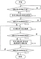
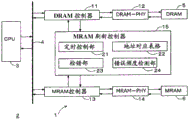
本发明的实施方式涉及存储器系统以及处理器系统。提供使非易失性存储器的数据保持特性提高的存储器系统以及处理器系统。根据一个方式的存储器系统,具备:非易失性存储器,具有易失性存储器的存储器容量以下的存储器容量,储存在所述易失性存储器中所储存的数据的至少一部分;第1控制部,刷新所述易失性存储器内的数据;以及第2控制部,在所述第1控制部刷新所述易失性存储器内的数据的第2期间与接下来进行刷新的第3期间之间的第1期间内,将从所述易失性存储器读出的数据重写到所述非易失性存储器。

Figure 201710158475

Embodiments of the invention relate to memory systems and processor systems. Provided are a memory system and a processor system that improve the data retention characteristics of a nonvolatile memory. According to one aspect, a memory system includes: a nonvolatile memory having a memory capacity equal to or less than a memory capacity of a volatile memory, and storing at least a part of data stored in the volatile memory; and a first control unit, Refreshing data in the volatile memory; and a second control unit for a period between a second period in which the first control unit refreshes the data in the volatile memory and a third period in which refresh is performed next In the first period, the data read from the volatile memory is rewritten to the nonvolatile memory.

Figure 201710158475

Description

Memory system and processor system
This application is based on Japanese patent application 2016-. This application is incorporated by reference herein in its entirety.
Technical Field
Embodiments of the invention relate to a memory system and a processor system.
Background
MRAM (Magnetoresistive Random Access Memory) has a high rewriting speed even in a nonvolatile Memory, and application to a working Memory such as a main Memory or a cache Memory is being studied. In order to apply MRAM to a cache memory, if an MTJ element, which is an MRAM storage element, is an MTJ element that can be accessed at high speed, data retention characteristics are degraded, and there is a concern that a data retention time may become short in a high-temperature state or the like. Although it is also possible to maintain the data retention characteristic by performing the confirmation writing after the data writing or the like is accessed to the MRAM, if the access interval is longer than the data retention time, there is a fear that the data will disappear.
Regarding a nonvolatile memory including an MRAM, in order to prolong the retention time of data, writing is often performed under a high voltage condition of a high voltage and a long pulse. Therefore, power consumption increases and stress on the memory element also increases, and there is a technical problem that rewriting endurance deteriorates.
One aspect provides a memory system including:
a nonvolatile memory having a memory capacity equal to or less than a memory capacity of a volatile memory, and storing at least a part of data stored in the volatile memory;
a 1 st control unit that refreshes data in the volatile memory; and
and a 2 nd control unit that rewrites data read from the volatile memory to the nonvolatile memory in a 1 st period between a 2 nd period in which the 1 st control unit refreshes data in the volatile memory and a 3 rd period in which the refresh is performed next.
Drawings
Fig. 1 is a block diagram showing a schematic configuration of a processor system including the memory system according to embodiment 1.
Fig. 2 is a block diagram showing a schematic configuration of a processor system in which fig. 1 is more specifically embodied.
Fig. 3 is a diagram showing refresh timings of the DRAM and the MRAM.
Fig. 4 is a flowchart showing the procedure of the refresh process of the MRAM according to embodiment 1.
Fig. 5 is a block diagram showing a schematic configuration of a processor system according to embodiment 2.
Fig. 6 is a flowchart showing the procedure of the refresh process of the MRAM according to embodiment 2.
Fig. 7 is a block diagram showing a schematic configuration of a processor system according to embodiment 3.
Fig. 8 is a block diagram showing a schematic configuration of a processor system according to embodiment 4.
Fig. 9 is a flowchart showing the procedure of the refresh process of the MRAM according to embodiment 4.
Fig. 10 is a flowchart showing a trigger signal output procedure of the MRAM of embodiment 4.
(symbol description)
1: a memory system; 2: a processor system; 3: a processor; 4: a bus; 5: a volatile memory; 6: a non-volatile memory; 7: 1 st refresh control unit; 8: a 2 nd refresh control section; 11: a DRAM controller; 12: DRAM-PHY; 13: an MRAM controller; 14: MRAM-PHY; 15: an MRAM refresh controller; 21: a timing control section; 22: an address correspondence table; 23: an error detection section; 24: an error frequency detection unit; 25: an error correction unit; 26: an error counter; 27: a count value determination unit; 28: a trigger signal generation unit.
Detailed Description
Embodiments of the present invention will be described below with reference to the drawings.
(embodiment 1)
Fig. 1 is a block diagram showing a schematic configuration of a processor system 2 including a memory system 1 according to embodiment 1. The processor system 2 of fig. 1 includes a processor (CPU) 3 and a memory system 1. The processor 3 and the memory system 1 transmit and receive data, addresses, and various control signals via the bus 4. The bus 4 includes a plurality of types of buses 4, such as a data bus for transmitting and receiving data, an address bus for transmitting and receiving an address, and a control signal bus for transmitting and receiving various control signals.
The memory system 1 includes a volatile memory 5, a nonvolatile memory 6, a 1 st refresh control unit (1 st control unit) 7, and a 2 nd refresh control unit (2 nd control unit) 8.
The volatile memory 5 may be built in the memory system 1, or may be detachably connected to the memory system 1. The volatile Memory 5 is constituted by, for example, a DRAM (Dynamic Random Access Memory). The volatile memory 5 needs to be periodically refreshed to retain stored data. In the refresh, the stored data is read out and rewritten. The refresh is performed every several tens to several hundreds of ms, for example.
The memory capacity of the nonvolatile memory 6 is equal to or less than the memory capacity of the volatile memory 5. The nonvolatile memory 6 stores at least a part of the data stored in the volatile memory 5. Typically, data that is frequently accessed by the processor 3 among data stored in the volatile memory 5 is stored in the nonvolatile memory 6. The nonvolatile memory 6 desirably uses a memory such as MRAM which can be accessed at high speed.
In the case where the nonvolatile memory 6 has higher access performance than the volatile memory 5, the nonvolatile memory 6 can be used as a memory having higher access priority than the volatile memory 5. For example, it is considered that the nonvolatile memory 6 is used as a cache memory, and the volatile memory 5 is used as a cache memory or a main memory having a lower access priority than the nonvolatile memory 6. In this case, the processor 3 accesses the nonvolatile memory 6 earlier than the volatile memory 5. For example, when the processor 3 writes data, the processor 3 writes data to the nonvolatile memory 6 earlier than to the volatile memory 5. The data written in the nonvolatile memory 6 is also written in the volatile memory 5 after that, but it is also possible to perform a basic operation of writing data in the volatile memory 5 by write through (write through) when the processor 3 writes data in the nonvolatile memory 6.
The 1 st refresh control section 7 refreshes the data in the volatile memory 5. The refresh is performed by every predetermined time for at least a part of the memory area within the volatile memory 5. More specifically, the 1 st refresh control unit 7 performs refresh every predetermined time while the processor 3 does not access the volatile memory 5.
The 2 nd refresh control unit 8 rewrites data read from the volatile memory 5 to the nonvolatile memory 6 in an interval between a refresh period in which the 1 st refresh control unit 7 refreshes data in the volatile memory 5 and a subsequent refresh period.
Fig. 2 is a block diagram showing a schematic configuration of the processor system 2 further embodying fig. 1. In fig. 2, an example is shown in which a DRAM5 is used as the volatile memory 5, and an MRAM6 is used as the nonvolatile memory 6. The processor system 2 of fig. 2 includes a DRAM5, a DRAM controller 11, a DRAM-PHY12, an MRAM6, an MRAM controller 13, an MRAM-PHY14, and an MRAM refresh controller 15, in addition to the processor 3(CPU) and the bus 4.
The DRAM controller 11 receives an access request from the processor 3 and controls access to the DRAM 5. The DRAM-PHY12 is an interface for connecting the DRAM5 and the DRAM controller 11 in accordance with the standard of the mounted DRAM 5. The DRAM controller 11 has the function of the 1 st refresh control section 7 shown in fig. 1. The DRAM controller 11 has a function of receiving a command request from the MRAM refresh controller 15 and transmitting received data.
The MRAM controller 13 receives an access request from the processor 3 and controls access to the MRAM 6. The MRAM-PHY14 is an interface for connecting the MRAM6 and the MRAM controller 13 in accordance with the standard of the MRAM6 mounted. The MRAM controller 13 has a function of receiving a command request from the MRAM refresh controller 15 and transmitting received data.
The MRAM refresh controller 15 has the function of the 2 nd refresh control section 8 shown in fig. 1, and controls refresh for the MRAM 6. The MRAM refresh controller 15 has a timing control section 21 and an address correspondence table 22. The timing control unit 21 controls the timing of refreshing the MRAM 6. The address correspondence table 22 is an associative memory unit for storing association information between data in the MRAM6 and data in the DRAM 5. The address correspondence table 22 is configured using, for example, a register, an SRAM, or the like. The MRAM refresh controller 15 has a function of transmitting and receiving commands and data to and from the DRAM controller 11 and the MRAM controller 13. The function of transmitting and receiving commands and data means, for example, an input/output system for commands and data and an input/output buffer area.
Fig. 3 is a diagram showing refresh timing of the DRAM5 and the MRAM 6. The refresh of the DRAM5 is performed for all or part of the memory area in the DRAM5 at predetermined time intervals while the processor 3 is not accessing the DRAM 5. The period in which the processor 3 does not perform access includes a period in which the processor 3 does not perform memory access although it is operating normally and a period in which the processor 3 is in the sleep mode.
Fig. 3 shows an example of refreshing the DRAM5 every 64 ms. In the example of fig. 3, the memory capacity of the DRAM5 is set to 1 gigabyte. If the refresh is performed 8192 times in 128 kbyte units and 110ns is required for every 1 access of DRAM5, the time required for refreshing the entire memory area in DRAM5 is 110ns × 8192, which is about 0.9 ms. Therefore, if the refresh interval is set to 64ms, 64-0.9 ═ 63.1ms is an idle time.
Therefore, the timing control unit 21 in the MRAM refresh controller 15 refreshes the MRAM6 using the idle time. For example, if the data forwarding rate from DRAM5 is set to 12.8GBbps, 0.01ms is required to forward 1 megabyte from DRAM5 to MRAM 6. In order to write 1 mbyte of data to the MRAM6, 5ns × 1M/256 is required to be 0.0195 ms. These periods are set to 0.03ms or less in combination. As described above, even if the memory capacities of the MRAM6 and the DRAM5 are the same, the time required for refreshing the MRAM6 is 1/10 or less of the DRAM5, and the MRAM6 can be refreshed intermittently and with a sufficient amount of time between refreshes of the DRAM 5.
Fig. 4 is a flowchart showing the procedure of the refresh processing of the MRAM6 of embodiment 1. First, the MRAM refresh controller 15 determines whether or not the refresh of the DRAM5 is started (step S1). Here, a command issued to DRAM5 by DRAM controller 11 is monitored, and if a refresh command is issued, it is detected that refresh of DRAM5 is started. More specifically, the timing control section 21 in the MRAM refresh controller 15 receives a control signal from the DRAM controller 11. When the timing control section 21 receives the refresh command, the processing from step S2 onward is started.
In step S2, the MRAM refresh controller 15 refers to the address correspondence table 22, and transmits a request to read out data in the DRAM5 corresponding to the data in the MRAM6 to the DRAM controller 11.
Thereafter, it stands by until the refresh of the DRAM5 is finished (step S3), and when the refresh of the DRAM5 is finished, the DRAM controller 11 reads out the corresponding data from the DRAM5 in accordance with the request of step S2, and transmits it to the MRAM refresh controller 15 (step S4).
The MRAM refresh controller 15 overwrites the corresponding data of the MRAM6 with the data read out from the DRAM5 (step S5). This causes the MRAM6 to be refreshed. In the refresh of the DRAM5, the process of rewriting the data read from the DRAM5 is performed, but in the refresh of the MRAM6 of the present embodiment, the data read from the DRAM5 is rewritten for the corresponding data of the MRAM 6. The reason for this is to consider that the reliability of data in the DRAM5 is higher than that in the MRAM 6. By performing the refresh of the MRAM6 using the data in the DRAM5, the MRAM6 can be made to have the retention characteristics equivalent to the DRAM 5.
In the above-described step S4, after the refresh of the DRAM5 is ended, the rewritten data is read out from the DRAM 5. The reason for this is that data read from DRAM5 at the time of refresh in DRAM5 is not output to the outside of DRAM5 in many cases. If data read from the DRAM5 can be output to the outside for refresh, the MRAM6 can be rewritten using the data.
As described above, in embodiment 1, since the data read from the DRAM5 is rewritten to the nonvolatile memory 6 in the intermittence between the refresh period of the DRAM5 and the next refresh period, the MRAM6 can be refreshed with the data in the DRAM5 at a frequency equivalent to that of the refresh of the DRAM5, and the retention characteristic of the MRAM6 can be secured as much as that of the DRAM 5.
(embodiment 2)
In embodiment 2, the MRAM6 is refreshed when there is an error in the data in the MRAM 6.
Fig. 5 is a block diagram showing a schematic configuration of the processor system 2 according to embodiment 2. The internal structure of the MRAM refresh controller 15 is different in the processor system 2 of fig. 5 compared to fig. 2, and the other structures are common.
The MRAM refresh controller 15 of fig. 5 includes an error detection unit 23 in addition to the timing control unit 21 and the address correspondence table 22 similar to those of fig. 2. The error detection section 23 detects whether or not the data read from the DRAM5 is different from the corresponding data within the MRAM 6. The error detection unit 23 may be mounted in a read circuit portion inside the MRAM 6. The MRAM refresh controller 15 rewrites data read out from the DRAM5 only for data within the MRAM6 in which an error is detected by the error detection section 23. This can reduce the number of data writes to the MRAM6 as compared with the case where all the data in the MRAM6 is rewritten.
Fig. 6 is a flowchart showing the procedure of the refresh processing of the MRAM6 of embodiment 2. Steps S11 to S14 of fig. 6 are the same as steps S1 to S4 of fig. 4. The error detector 23 reads out the corresponding data in the MRAM6 from the data read out from the DRAM5, compares the read data with the DRAM data, and detects whether or not the corresponding data in the MRAM6 has an error (step S15). Here, whether or not data has an error is detected for each line (line) which is a read unit of data in the MRAM 6. A row refers to data made up of a plurality of bits. If an error is detected, the corresponding data within the MRAM6 is rewritten with the data read out from the DRAM5 (step S16). The processing of steps S15, S16 may be implemented in the read and write circuit portion inside the MRAM6 or in the MRAM controller 13.
If no error is detected in step S15 or if the process of step S16 ends, it is determined whether or not the refreshing of the MRAM6 ends (step S16), and if data that has not been refreshed remains in the MRAM6, the process of step S14 and subsequent steps is repeated. If it is determined in step S16 that no residue remains, the process ends.
In this manner, the DRAM5 and the MRAM6 are refreshed in units of bit string data (row data) composed of a plurality of bits. The error detector 23 compares the data read from the DRAM5 with the corresponding data in the MRAM6, and detects whether or not there is an error for each bit or row. For example, when an error occurs in only a part of bits in data read from the MRAM6, the MRAM6 may be rewritten for each row data read from the DRAM5, or only bits in the row data read from the DRAM5 for which an error is detected by the error detector 23 may be rewritten to the MRAM 6.
As described above, in embodiment 2, only when the data read from the DRAM5 is different from the corresponding data in the MRAM6, the corresponding data in the MRAM6 is overwritten with the data read from the DRAM5, so that the amount of data to be refreshed can be reduced, power consumption can be reduced, the number of writes to the MRAM6 can be reduced, and the reliability of the MRAM chip can be improved.
(embodiment 3)
In embodiment 3, the refresh cycle for refreshing the MRAM6 is controlled in accordance with the error frequency of data in the MRAM 6.
Fig. 7 is a block diagram showing a schematic configuration of the processor system 2 according to embodiment 3. The internal structure of the MRAM refresh controller 15 is different in the processor system 2 of fig. 7 compared to fig. 5, and the other structures are common.
The MRAM refresh controller 15 in fig. 7 includes an error frequency detection unit 24 in addition to the timing control unit 21, the address correspondence table 22, and the error detection unit 23, which are similar to those in fig. 5.
The error frequency detecting unit 24 detects the error frequency of the data stored in the MRAM 6. More specifically, the error frequency detecting unit 24 detects, for example, the number of data errors per unit time or the bit error rate of the MRAM6 as an error frequency based on the detection result of the error detecting unit 23.
The timing control unit 21 controls the refresh period based on the error frequency detected by the error frequency detection unit 24. More specifically, the timing control unit 21 increases the refresh frequency as the error frequency increases. As an example, it is conceivable that the MRAM6 is refreshed at a rate of 1 time among a plurality of refresh periods of the DRAM5 when the error frequency is low, and the MRAM6 is refreshed every time each refresh period of the DRAM5 ends if the error frequency is high.
Embodiment 3 can be combined with embodiment 1 or embodiment 2. That is, the timing control unit 21 controls the refresh interval for performing the processing in the flowchart of fig. 4 or 6, based on the error frequency of the MRAM 6.
As described above, in embodiment 3, the refresh cycle of the MRAM6 is controlled in accordance with the error frequency of data in the MRAM6, and therefore, when the error frequency of the MRAM6 increases due to an increase in temperature or the like, the refresh cycle can be shortened to prevent the data retention characteristics from decreasing. In addition, when the error frequency of the MRAM6 is low, the number of writes to the MRAM6 and power consumption can be reduced by extending the refresh cycle.
(embodiment 4)
In embodiment 4, the MRAM6 is refreshed against Error bits existing in the data in the MRAM6 and rows within a range where Error Checking and Correcting (ECC) can be performed.
Fig. 8 is a block diagram showing a schematic configuration of the processor system 2 according to embodiment 4. The internal structure of the MRAM refresh controller 15 is different in the processor system 2 of fig. 8 compared to fig. 2, and the other structures are common.
The MRAM refresh controller 15 in fig. 8 includes an error detection unit 23, an error correction unit 25, an error counter 26, a count value determination unit 27, and a trigger signal generation unit 28, in addition to the timing control unit 21 and the address correspondence table 22 similar to those in fig. 2.
The error detection section 23 detects whether or not the data in the MRAM6 has an error for each bit or row. The error correction unit 25 corrects error bits within a predetermined number of bits included in data in the nonvolatile memory 6. The error counter 26 increments the count when detecting a bit different from the corresponding data within the MRAM6 in the data read out from the DRAM 5. The count value determination unit 27 determines whether or not the count value of the error counter 26 exceeds a predetermined threshold value.
When the count value determination unit 27 determines that the threshold value is exceeded, the MRAM refresh controller 15 rewrites data read from the DRAM5 to the MRAM 6.
When the count value determination unit 27 determines that the threshold value is exceeded, the trigger signal generation unit 28 generates and outputs a trigger signal. The trigger signal becomes a signal indicating the refresh of the MRAM 6. When the trigger signal is output, the MRAM refresh controller 15 starts a refresh processing procedure described later. The more errors in the MRAM6, the larger the count value of the error counter 26, and the faster the trigger signal is output. That is, the more bit errors within the MRAM6, the shorter the refresh period.
Fig. 9 is a flowchart showing the procedure of the refresh processing of the MRAM6 of embodiment 4. First, the MRAM refresh controller 15 determines whether or not the trigger signal is output from the trigger signal generation unit 28 (step S21). If the trigger signal is not output, the MRAM6 is not refreshed, and the process of fig. 9 is ended. If the trigger signal is output, the timing control section 21 determines whether or not the refresh of the DRAM5 is started (step S22), and if not, waits until the refresh of the DRAM5 is started. Here, timing control unit 21 monitors issuance of a refresh command to DRAM5, and if the refresh command is issued, determines that refresh of DRAM5 is started.
If the refresh of the DRAM5 is started, the MRAM refresh controller 15 refers to the address correspondence table 22, and transmits a read request of data in the DRAM5 corresponding to the data in the MRAM6 to the DRAM controller 11 (step S23).
The read request corresponding to all the data in the MRAM6 or the read request corresponding to partial data may be transmitted at this time.
If the refresh of the DRAM5 is finished (step S24), the DRAM controller 11 reads out the data of the DRAM5 in accordance with the read request of step S23, and sends it to the MRAM refresh controller 15 (step S25).
Finally, the corresponding data within the MRAM6 is rewritten with the data read out from the DRAM5 (step S26). When an error occurs in only some of the bits in the MRAM6, the error may be rewritten to the MRAM6 in units of the line data read from the DRAM5, or only the bit in the line data read from the DRAM5 in which the error is detected by the error detection unit 23 may be rewritten to the MRAM 6. At this time, the process of step S26 may be implemented in the read and write circuit portion inside the MRAM 6.
Fig. 10 is a flowchart showing a trigger signal output step of the MRAM6 of embodiment 4. First, when there is a read access from the processor 3 to the MRAM6 via the MRAM controller 13, the process of fig. 10 is started (step S31). Next, data is read out from the MRAM6, and after error correction by ECC processing, the read data as the MRAM6 is forwarded to the CPU 3. That is, it is determined whether or not there is a data error in the MRAM6 (step S32), and if there is an error, correction is performed if the number of bits is equal to or less than the number of correctable bits (step S33, correction possible/impossible determination unit).
If it is determined in step S33 that error correction is not possible, a trigger signal is output (step S34). At this time, the addresses are also simultaneously output, so that the MRAM refresh target address is limited, and the refresh time and power can be reduced.
If it is determined in step S33 that error correction is possible, the error counter 26 is incremented (step S35). When the error counter reaches a predetermined value or more (step S36), a trigger signal is output (step S34).
In embodiment 4, the error detection unit 23 and the error correction unit 25 may be implemented in the read and write circuit portion inside the MRAM6, or may be implemented in the MRAM controller 13.
As described above, in embodiment 4, the trigger signal is immediately output when there is a bit error exceeding the error correctable limit in the data in the MRAM6, the error counter 26 is incremented when there is an error within the error correctable range, and the MRAM6 is refreshed when the count value of the error counter 26 exceeds the threshold value, so that the refresh timing of the MRAM6 can be variably controlled in accordance with the degree of error in the MRAM 6. Therefore, it is not necessary to perform wasteful refresh while maintaining the retention characteristic of the MRAM6, and therefore, power consumption and the number of times of rewriting can be reduced.
In the above-described embodiments 1 to 4, the MRAM6 is refreshed using the data read from the DRAM5 after the refresh of the DRAM5 is completed, but a high-speed volatile memory (for example, SRAM) for storing data of the amount for which the refresh of the MRAM6 is performed may be provided separately from the DRAM5, and the data for the refresh of the MRAM6 may be read from the SRAM instead of the DRAM 5. In this case, when a data write request is issued from the processor 3, the data is written not only to the DRAM5 but also to the SRAM, and the data in the SRAM may be used for refreshing the MRAM6 before being sent to the DRAM 5.
In the above-described embodiments 3 and 4, whether or not data in the MRAM6 has an error is detected, but the ambient temperature may be measured without measuring the error frequency, or the ambient temperature may be measured in addition to the error frequency, and the refresh interval may be shortened when the ambient temperature is out of a predetermined set range.
In the above-described embodiments 1 to 4, the example in which the DRAM5 is used as the volatile memory 5 and the MRAM6 is used as the nonvolatile memory 6 has been described, but this is an example, and other types of volatile memory 5 and nonvolatile memory 6 may be used.
Similarly to the nonvolatile Memory 6, the volatile Memory 5 may be detachably connected to the Memory system 1, for example, as a Dual Inline Memory Module (DIMM). The volatile memory 5 and the processor 3 may be integrated into a single chip, or the volatile memory 5 and the nonvolatile memory 6 may be integrated into a single chip with the processor 3. In this manner, the embodiments of the volatile memory 5 and the nonvolatile memory 6 are not particularly limited.
At least a part of the processor system 2 and the memory system 1 described in the above embodiments may be configured by hardware or software. When the software is configured, a program that realizes at least some of the functions of the processor system 2 and the memory system 1 may be stored in a recording medium such as a flexible disk or a CD-ROM, and may be read and executed by a computer. The recording medium is not limited to a removable recording medium such as a magnetic disk or an optical disk, and may be a fixed recording medium such as a hard disk device or a memory.
Further, the program that realizes at least part of the functions of the processor system 2 and the memory system 1 may be distributed via a communication line such as the internet (including wireless communication). Further, the program may be distributed in an encrypted, modulated, and compressed state via a wired line such as the internet, a wireless line, or a recording medium.
The above embodiments can be summarized as the following embodiments.
Technical solution 1
A memory system is provided with:
a nonvolatile memory having a memory capacity equal to or less than a memory capacity of a volatile memory, and storing at least a part of data stored in the volatile memory;
a 1 st control unit that refreshes data in the volatile memory; and
and a 2 nd control unit that rewrites data read from the volatile memory to the nonvolatile memory in a 1 st period between a 2 nd period in which the 1 st control unit refreshes data in the volatile memory and a 3 rd period in which the refresh is performed next.
Technical solution 2
According to claim 1, the 2 nd control unit rewrites data corresponding to the data read from the volatile memory in at least a part of the memory area in the nonvolatile memory in the 1 st period.
Technical solution 3
According to claim 1 or 2, the nonvolatile memory device includes a related information storage unit that stores related information between an address of data in the nonvolatile memory and an address of data in the volatile memory,
the 2 nd control unit rewrites data in the nonvolatile memory corresponding to the data read from the volatile memory, based on the related information.
Technical solution 4
According to any one of claims 1 to 3, the 2 nd control unit reads data from the volatile memory in the 1 st period after the refresh of the data in the volatile memory by the 1 st control unit is completed, and rewrites the read data in the nonvolatile memory.
Technical solution 5
According to any one of claims 1 to 4, the 2 nd control unit controls whether or not to rewrite the data read from the volatile memory to the nonvolatile memory in units of bits or lines.
Technical scheme 6
According to any one of claims 1 to 5, the 2 nd control unit rewrites data read from the volatile memory to the nonvolatile memory while the processor is in the sleep mode.
Technical scheme 7
According to any one of claims 1 to 6, the nonvolatile memory device is provided with an error detection unit that detects whether or not data read from the volatile memory is different from corresponding data in the nonvolatile memory,
the 2 nd control unit rewrites the data read from the volatile memory to the nonvolatile memory when the error detection unit detects a difference.
Technical solution 8
According to claim 7, the 2 nd control unit rewrites a bit different from the corresponding data in the nonvolatile memory, in the bit sequence of the data read from the volatile memory, based on the detection result of the error detection unit.
Technical solution 9
According to any one of claims 1 to 8, an error frequency detecting unit that detects an error frequency of data stored in the nonvolatile memory is provided,
the 2 nd control unit controls a refresh cycle of rewriting data read from the volatile memory to the nonvolatile memory, based on the error frequency.
Technical means 10
According to claim 9, the method comprises:
an error correction unit that corrects error bits within a predetermined number of bits included in data in the nonvolatile memory;
a correction-enabled/disabled determination unit that determines whether or not the data read from the volatile memory can be corrected by the error correction unit;
a counter that counts up the number of data read from the volatile memory when the data has an error and the correction-possible/impossible determining unit determines that the error correction is possible;
a count value determination unit configured to determine whether or not a count value of the counter exceeds a predetermined threshold; and
a trigger signal generation unit that generates a trigger signal when the correction impossible determination unit determines that the correction is impossible or when the count value determination unit determines that the threshold value is exceeded,
the 2 nd control unit rewrites data read from the volatile memory to the nonvolatile memory in the 1 st period after the trigger signal is generated.
Technical means 11
According to any one of claims 1 to 10, the nonvolatile memory is a cache memory implemented by a processor with higher access priority than the volatile memory,
the data writing method includes a cache controller that writes data to the volatile memory in a write-through mode when the data is written to the nonvolatile memory in response to a write request issued by the processor.
Technical means 12
According to any one of claims 1 to 11, the nonvolatile Memory includes an MRAM (Magnetoresistive Random Access Memory).
Technical means 13
A processor system is provided with:
a processor; and
a memory system accessed by the processor,
the memory system has:
a nonvolatile memory having a memory capacity equal to or less than a memory capacity of a volatile memory, and storing at least a part of data stored in the volatile memory;
a 1 st control unit that refreshes data in the volatile memory; and
and a 2 nd control unit that rewrites data read from the volatile memory to the nonvolatile memory in a 1 st period between a 2 nd period in which the 1 st control unit refreshes data in the volatile memory and the 3 rd period in which the refresh is performed next.
While several embodiments of the present invention have been described, these embodiments have been presented by way of example only, and are not intended to limit the scope of the invention. These novel embodiments can be implemented in other various ways, and various omissions, substitutions, and changes can be made without departing from the spirit of the invention. These embodiments and modifications thereof are included in the scope and gist of the invention, and are described in the invention recited in the claims and the equivalent scope thereof.

Claims (11)

1. A memory system is provided with:
a nonvolatile memory having a memory capacity equal to or less than a memory capacity of a volatile memory, and storing at least a part of data stored in the volatile memory;
a 1 st control unit that refreshes data in the volatile memory; and
and a 2 nd control unit that rewrites data read from the volatile memory to the nonvolatile memory in a 1 st period between a 2 nd period in which the 1 st control unit refreshes data in the volatile memory and a 3 rd period in which the refresh is performed next.
2. The memory system according to claim 1,
the 2 nd control unit rewrites data corresponding to the data read from the volatile memory in at least a part of the memory area in the nonvolatile memory in the 1 st period.
3. The memory system according to claim 1,
a related information storage unit for storing related information between an address of data in the nonvolatile memory and an address of data in the volatile memory,
the 2 nd control unit rewrites data in the nonvolatile memory corresponding to the data read from the volatile memory, based on the related information.
4. The memory system according to claim 2,
a related information storage unit for storing related information between an address of data in the nonvolatile memory and an address of data in the volatile memory,
the 2 nd control unit rewrites data in the nonvolatile memory corresponding to the data read from the volatile memory, based on the related information.
5. The memory system according to any one of claims 1 to 4,
the 2 nd control unit reads data from the volatile memory in the 1 st period after the refresh of data in the volatile memory by the 1 st control unit is completed, and rewrites the read data in the nonvolatile memory.
6. The memory system according to any one of claims 1 to 4,
the 2 nd control unit controls whether or not to rewrite the data read from the volatile memory to the nonvolatile memory in units of bits or lines.
7. The memory system according to any one of claims 1 to 4,
the 2 nd control unit rewrites data read from the volatile memory to the nonvolatile memory while the processor is in the sleep mode.
8. The memory system according to any one of claims 1 to 4,
the nonvolatile memory device includes an error detection unit that detects whether or not data read from the volatile memory is different from corresponding data in the nonvolatile memory,
the 2 nd control unit rewrites the data read from the volatile memory to the nonvolatile memory when the error detection unit detects a difference.
9. The memory system according to claim 8,
the 2 nd control unit rewrites a bit different from the corresponding data in the nonvolatile memory in a bit sequence of the data read from the volatile memory, based on a detection result of the error detection unit.
10. The memory system according to any one of claims 1 to 4,
an error frequency detecting unit that detects an error frequency of data stored in the nonvolatile memory,
the 2 nd control unit controls a refresh cycle of rewriting data read from the volatile memory to the nonvolatile memory, based on the error frequency.
11. The memory system according to claim 10, comprising:
an error correction unit that corrects error bits within a predetermined number of bits included in data in the nonvolatile memory;
a correction-enabled/disabled determination unit that determines whether or not the data read from the volatile memory can be corrected by the error correction unit;
a counter that counts up the number of data read from the volatile memory when the data has an error and the correction-possible/impossible determining unit determines that the error correction is possible;
a count value determination unit configured to determine whether or not a count value of the counter exceeds a predetermined threshold; and
a trigger signal generation unit that generates a trigger signal when the correction impossible determination unit determines that the correction is impossible or when the count value determination unit determines that the threshold value is exceeded,
the 2 nd control unit rewrites data read from the volatile memory to the nonvolatile memory in the 1 st period after the trigger signal is generated.
CN201710158475.7A 2016-09-20 2017-03-17 memory system and processor system Active CN107845397B (en)

Applications Claiming Priority (2)

Application Number Priority Date Filing Date Title
JP2016-183313 2016-09-20
JP2016183313A JP6697360B2 (en) 2016-09-20 2016-09-20 Memory system and processor system

Publications (2)

Publication Number Publication Date
CN107845397A CN107845397A (en) 2018-03-27
CN107845397B true CN107845397B (en) 2021-07-27

Family

ID=61618050

Family Applications (1)

Application Number Title Priority Date Filing Date
CN201710158475.7A Active CN107845397B (en) 2016-09-20 2017-03-17 memory system and processor system

Country Status (4)

Country Link
US (1) US10528270B2 (en)
JP (1) JP6697360B2 (en)
CN (1) CN107845397B (en)
TW (1) TWI655574B (en)

Families Citing this family (13)

* Cited by examiner, † Cited by third party
Publication number Priority date Publication date Assignee Title
JP6083480B1 (en) * 2016-02-18 2017-02-22 日本電気株式会社 Monitoring device, fault tolerant system and method
CN110729006B (en) * 2018-07-16 2022-07-05 超威半导体(上海)有限公司 Refresh Schemes in Memory Controllers
US11516042B2 (en) * 2018-07-19 2022-11-29 Panasonic Intellectual Property Management Co., Ltd. In-vehicle detection system and control method thereof
US10847198B2 (en) * 2018-11-01 2020-11-24 Spin Memory, Inc. Memory system utilizing heterogeneous magnetic tunnel junction types in a single chip
US10971681B2 (en) 2018-12-05 2021-04-06 Spin Memory, Inc. Method for manufacturing a data recording system utilizing heterogeneous magnetic tunnel junction types in a single chip
JP7219397B2 (en) * 2019-01-18 2023-02-08 富士通株式会社 Information processing device, storage control device and storage control program
CN111274162B (en) * 2020-03-27 2025-02-28 西安紫光国芯半导体股份有限公司 Dual in-line memory module device of storage-level memory and data access method
WO2022095786A1 (en) * 2020-11-03 2022-05-12 北京灵汐科技有限公司 Memory and neuromorphic chip, and data processing method
JP2022094017A (en) * 2020-12-14 2022-06-24 トヨタ自動車株式会社 On-vehicle system
CN115188401B (en) * 2021-04-07 2025-10-14 浙江驰拓科技有限公司 Devices for protecting MRAM data
US12530128B2 (en) * 2021-11-12 2026-01-20 Samsung Electronics Co., Ltd. Memory system for backing up data in case of sudden power-off and operation method thereof
US12591371B2 (en) * 2022-11-08 2026-03-31 Micron Technology, Inc. Memory sub-system for memory cell in-field touch-up
US12579027B2 (en) * 2023-07-05 2026-03-17 Micron Technology, Inc. Data protection with time-varying in-situ data refresh

Family Cites Families (29)

* Cited by examiner, † Cited by third party
Publication number Priority date Publication date Assignee Title
JPS602861B2 (en) 1978-10-03 1985-01-24 リズム時計工業株式会社 Manufacturing method of motor core
JPS5834303A (en) 1981-08-25 1983-02-28 Toyoda Autom Loom Works Ltd Hole pitch measuring device
US5197026A (en) * 1989-04-13 1993-03-23 Microchip Technology Incorporated Transparent EEPROM backup of DRAM memories
JP2742481B2 (en) * 1991-10-14 1998-04-22 シャープ株式会社 Dynamic semiconductor memory device
JP4049297B2 (en) * 2001-06-11 2008-02-20 株式会社ルネサステクノロジ Semiconductor memory device
US6704230B1 (en) * 2003-06-12 2004-03-09 International Business Machines Corporation Error detection and correction method and apparatus in a magnetoresistive random access memory
JP4118249B2 (en) 2004-04-20 2008-07-16 株式会社東芝 Memory system
JP2009087509A (en) 2007-10-03 2009-04-23 Toshiba Corp Semiconductor memory device
JP5049733B2 (en) * 2007-10-17 2012-10-17 株式会社東芝 Information processing system
JP5834303B2 (en) 2008-12-30 2015-12-16 ラウンド ロック リサーチ リミテッド ライアビリティー カンパニー Non-volatile memory with extended operating temperature range
US8924661B1 (en) * 2009-01-18 2014-12-30 Apple Inc. Memory system including a controller and processors associated with memory devices
US20100195393A1 (en) * 2009-01-30 2010-08-05 Unity Semiconductor Corporation Data storage system with refresh in place
US8572455B2 (en) * 2009-08-24 2013-10-29 International Business Machines Corporation Systems and methods to respond to error detection
JP4956640B2 (en) * 2009-09-28 2012-06-20 株式会社東芝 Magnetic memory
DE112009005413B4 (en) 2009-12-02 2018-11-29 Micron Technology, Inc. Update method for non-volatile memory and non-volatile memory device
JP5454408B2 (en) * 2010-07-30 2014-03-26 セイコーエプソン株式会社 Sensing device and electronic device
JP6043478B2 (en) * 2010-12-07 2016-12-14 三星電子株式会社Samsung Electronics Co.,Ltd. Storage node including free magnetic layer of magnetic anisotropic material, magnetic memory device including the same, and manufacturing method thereof
JP2013062419A (en) 2011-09-14 2013-04-04 Toshiba Corp Semiconductor memory and method of manufacturing the same
US9336133B2 (en) * 2012-12-31 2016-05-10 Sandisk Technologies Inc. Method and system for managing program cycles including maintenance programming operations in a multi-layer memory
JP2014157391A (en) 2013-02-14 2014-08-28 Sony Corp Storage control device, storage device, information processing system, and storage control method
TWI489469B (en) * 2013-03-26 2015-06-21 Phison Electronics Corp Data reading method, and control circuit, memory module and memory storage apparatus and memory module using the same
TWI470431B (en) * 2013-06-14 2015-01-21 Phison Electronics Corp Data writing method, memory controller and memory storage apparatus
JP6275427B2 (en) * 2013-09-06 2018-02-07 株式会社東芝 Memory control circuit and cache memory
CN103500131B (en) * 2013-09-18 2015-09-09 华为技术有限公司 A kind of storage system power failure data backup method and controller system memory
US20150206574A1 (en) * 2014-01-22 2015-07-23 Advanced Micro Devices, Inc. Relocating infrequently-accessed dynamic random access memory (dram) data to non-volatile storage
US9887008B2 (en) * 2014-03-10 2018-02-06 Futurewei Technologies, Inc. DDR4-SSD dual-port DIMM device
KR20150120558A (en) * 2014-04-17 2015-10-28 에스케이하이닉스 주식회사 Volatile memory device, memory module including the same and operation method of the memory module
DE102014208609A1 (en) * 2014-05-08 2015-11-26 Robert Bosch Gmbh Refresh a memory area of a non-volatile memory unit
KR102326018B1 (en) * 2015-08-24 2021-11-12 삼성전자주식회사 Memory system

Also Published As

Publication number Publication date
US10528270B2 (en) 2020-01-07
US20180081570A1 (en) 2018-03-22
JP2018049671A (en) 2018-03-29
JP6697360B2 (en) 2020-05-20
CN107845397A (en) 2018-03-27
TW201814492A (en) 2018-04-16
TWI655574B (en) 2019-04-01

Similar Documents

Publication Publication Date Title
CN107845397B (en) memory system and processor system
CN110120243B (en) Semiconductor memory device, method of operating same, and memory system
KR102658230B1 (en) Semiconductor memory devices, memory systems including the same and method of operating semiconductor memory devices
KR101046304B1 (en) Memory device and refresh adjustment method
US10692561B2 (en) Semiconductor memory device, memory system, and refresh method thereof
US9087614B2 (en) Memory modules and memory systems
KR102787324B1 (en) Semiconductor memory devices and memory systems including the same
US8478929B2 (en) Data processing semiconductor device
JP5490062B2 (en) Nonvolatile semiconductor memory device
US8910018B2 (en) Memory with dynamic error detection and correction
CN111352756B (en) Apparatus for detecting errors in data stored in a memory device and method of operating the same
KR20220039432A (en) Semiconductor memory devices and methods of operating the same
TW201911049A (en) Shared address counter for multiple modes of operation in a memory device
KR20220060156A (en) Semiconductor memory devices and method of operating semiconductor memory devices
US20070133315A1 (en) Dynamic random access memory device and associated refresh cycle
JP2020042890A (en) Memory system and controlling method of memory system
KR102468710B1 (en) Memory system including memory device and memory controller, and operation method thereof
US20210216419A1 (en) Memory module, memory system including the same and operation method thereof
JP2007293846A (en) Method and system for performing maintenance and calibration operations for memory
US20250036521A1 (en) Semiconductor memory device and operating method thereof
US12327582B2 (en) Memory device and operating method with mechanism to determine victim rows for refreshing
KR20130136341A (en) Semiconductor device and operating method thereof
JP6448254B2 (en) Memory control device and memory control method
KR20250053525A (en) A memory device and a method of operating the same device

Legal Events

Date Code Title Description
PB01 Publication
PB01 Publication
SE01 Entry into force of request for substantive examination
CB02 Change of applicant information

Address after: Tokyo, Japan

Applicant after: Kaixia Co.,Ltd.

Address before: Tokyo, Japan

Applicant before: TOSHIBA MEMORY Corp.

Address after: Tokyo, Japan

Applicant after: TOSHIBA MEMORY Corp.

Address before: Tokyo, Japan

Applicant before: Japanese businessman Panjaya Co.,Ltd.

TA01 Transfer of patent application right

Effective date of registration: 20200312

Address after: Tokyo, Japan

Applicant after: Japanese businessman Panjaya Co.,Ltd.

Address before: Tokyo, Japan

Applicant before: TOSHIBA MEMORY Corp.

Effective date of registration: 20200312

Address after: Tokyo, Japan

Applicant after: TOSHIBA MEMORY Corp.

Address before: Tokyo, Japan

Applicant before: Toshiba Corp.

GR01 Patent grant
GR01 Patent grant