CN107798665B - Underwater image enhancement method based on structure-texture layering - Google Patents
Underwater image enhancement method based on structure-texture layering Download PDFInfo
- Publication number
- CN107798665B CN107798665B CN201711086095.3A CN201711086095A CN107798665B CN 107798665 B CN107798665 B CN 107798665B CN 201711086095 A CN201711086095 A CN 201711086095A CN 107798665 B CN107798665 B CN 107798665B
- Authority
- CN
- China
- Prior art keywords
- image
- layer
- texture
- transmittance
- noise
- Prior art date
- Legal status (The legal status is an assumption and is not a legal conclusion. Google has not performed a legal analysis and makes no representation as to the accuracy of the status listed.)
- Expired - Fee Related
Links
Images


Classifications
-
- G—PHYSICS
- G06—COMPUTING OR CALCULATING; COUNTING
- G06T—IMAGE DATA PROCESSING OR GENERATION, IN GENERAL
- G06T5/00—Image enhancement or restoration
- G06T5/70—Denoising; Smoothing
-
- G—PHYSICS
- G06—COMPUTING OR CALCULATING; COUNTING
- G06T—IMAGE DATA PROCESSING OR GENERATION, IN GENERAL
- G06T5/00—Image enhancement or restoration
- G06T5/40—Image enhancement or restoration using histogram techniques
-
- G—PHYSICS
- G06—COMPUTING OR CALCULATING; COUNTING
- G06T—IMAGE DATA PROCESSING OR GENERATION, IN GENERAL
- G06T5/00—Image enhancement or restoration
- G06T5/80—Geometric correction
Landscapes
- Physics & Mathematics (AREA)
- General Physics & Mathematics (AREA)
- Engineering & Computer Science (AREA)
- Theoretical Computer Science (AREA)
- Image Processing (AREA)
Abstract
Description
技术领域technical field
本发明属于计算机视觉领域,涉及基于结构-纹理分层的水下图像增强方法。具体而言,通过分层处理将图像分为高频纹理层和低频结构层,不仅避免了在增强过程中将噪声放大问题,而且很好的保留了细节和边缘,改善了对比度和色调自然性,即基于结构-纹理分层的水下图像增强方法。The invention belongs to the field of computer vision, and relates to an underwater image enhancement method based on structure-texture layering. Specifically, the image is divided into a high-frequency texture layer and a low-frequency structure layer by layering, which not only avoids the problem of amplifying noise during the enhancement process, but also preserves details and edges, improving contrast and tone naturalness. , which is an underwater image enhancement method based on structure-texture layering.
背景技术Background technique
清晰、可见度高的水下图像分析和识别对水下勘测、水下视频、军事等方面的研究具有非常重要的意义。但是,在复杂的水下成像环境中,由于在传输过程中的大悬浮粒子(像水中的浑浊粒子)吸收和散射的影响,严重降低了图像质量。因此,典型的水下图像存在着如下问题:Clear and high-visibility underwater image analysis and recognition is of great significance to research in underwater surveying, underwater video, and military research. However, in the complex underwater imaging environment, the image quality is severely degraded due to the effect of absorption and scattering by large suspended particles (like turbid particles in water) during transmission. Therefore, typical underwater images have the following problems:
1)汇聚光照明,形成背景灰度分布不均匀;1) Concentrated light illumination, resulting in uneven distribution of background grayscale;
2)吸收、散射效应使得水下图像存在非均匀亮度和细节模糊问题;2) Absorption and scattering effects make underwater images non-uniform brightness and detail blurring;
3)照明条件不良,引起色调衰减、对比度降低问题;3) The lighting conditions are poor, causing the problem of tone attenuation and contrast reduction;
由于拍到的水下图像质量普遍较差,所以对水下图像进行目标识别前要进行预处理。目前存在的水下图像增强方法主要有以下几个发展阶段:Since the quality of the underwater images captured is generally poor, preprocessing should be performed before target recognition is performed on the underwater images. The existing underwater image enhancement methods mainly have the following development stages:
第一阶段:用传统的图像增强方法对水下图像处理,如:灰度变化、直方图均衡化、图像空域平滑和锐化处理、伪彩色处理等。但是由于水下成像特性的独特性,这些传统的方法处理结果并不理想。The first stage: use traditional image enhancement methods to process underwater images, such as: grayscale changes, histogram equalization, image spatial domain smoothing and sharpening, and pseudo-color processing. However, due to the unique characteristics of underwater imaging, the results of these traditional methods are not ideal.
第二阶段:根据水下和雾霾中成像特点的相似性,研究人员开始基于去雾技术对水下图像增强方法展开研究,但是,由于水中和空气中的透射率和吸收散射特点有差别,直接把去雾的方法用于水下图像增强会存在一些问题,例如在暗区域会丢失一些细节,在亮的区域引起过曝光现象。The second stage: According to the similarity of imaging characteristics in underwater and haze, researchers began to study underwater image enhancement methods based on dehazing technology. However, due to the difference in transmittance and absorption and scattering characteristics in water and air, There are some problems in directly applying the dehazing method to underwater image enhancement, such as loss of details in dark areas and overexposure in bright areas.
第三阶段:随着对水下折射和散射特性的研究,研究人员提出了一些专门的水下数学成像模型以及一些针对水下图像增强的方法。这些方法主要出发点是背景光估计、透射率估计、弥补光波衰减、基于融合原则增强等。例如:参考文献中提到的用基于分层的方法估计了背景光;基于四叉树分解和图像分块的全局背景光的估计方法,以及提出一种针对水下成像特点的最小信息损失的透射率估计算法;通过人造灯光弥补方法来增强水下图像的系统方法;通过融合四个权重进而增加了水下降质图像的可见度。这些方法在一定程度上抑制了过曝光和噪声问题,对图像的色调也有所改善,但是仍然存在部分细节丢失、噪声放大、色调不自然、过饱和等问题。这些问题会对水下研究产生很大的影响,因此,设计一种更好的水下图像增强方法,尽可能的提高图像对比度、突出感兴趣的细节和特征、改善图像的视觉效果、提供清晰、适于分析的图像是十分必要的。The third stage: With the study of underwater refraction and scattering properties, researchers have proposed some specialized underwater mathematical imaging models and some methods for underwater image enhancement. The main starting points of these methods are background light estimation, transmittance estimation, compensation for light wave attenuation, enhancement based on fusion principle, etc. For example: the background light is estimated by the layer-based method mentioned in the reference; the estimation method of the global background light based on quadtree decomposition and image segmentation, and a method for the minimum information loss of underwater imaging characteristics is proposed. A transmittance estimation algorithm; a systematic approach to enhancing underwater images through artificial light compensation methods; increasing the visibility of underwater degraded images by fusing four weights. These methods suppress the overexposure and noise problems to a certain extent, and also improve the color tone of the image, but there are still some problems such as loss of details, noise amplification, unnatural color tone, and oversaturation. These problems will have a great impact on underwater research. Therefore, a better underwater image enhancement method is designed to improve the image contrast as much as possible, highlight the details and features of interest, improve the visual effect of the image, provide clarity , An image suitable for analysis is necessary.
发明内容SUMMARY OF THE INVENTION
本发明意在弥补现有技术的不足,即实现在提高图像对比度的同时保留好的细节,在抑制噪声的同时保持色调的自然性。本发明采取的技术方案是,基于结构-纹理分层的水下图像增强方法,首先,通过直方图均衡化进行色彩校正,然后这个色彩纠正后的图被分解为低频结构层和高频纹理层。将噪声残留到纹理层,然后基于已经提出的雾线模型,从没有噪声的结构层精确地估计出的透射率,进而进行增强处理,再用梯度残留最小化方法增强纹理层,之后,通过适当的尺度伸缩,将增强后的结构层、纹理层和精细化的边缘掩膜重构成最终的增强图,从而解决已有技术无法处理的问题。The present invention is intended to make up for the deficiencies of the prior art, that is, to improve the contrast of the image while retaining good details, and to suppress the noise while maintaining the naturalness of the color tone. The technical scheme adopted in the present invention is that, for an underwater image enhancement method based on structure-texture layering, first, color correction is performed through histogram equalization, and then the color-corrected image is decomposed into a low-frequency structure layer and a high-frequency texture layer . Residual noise to the texture layer, and then based on the proposed fog line model, accurately estimated transmittance from the structure layer without noise, and then perform enhancement processing, and then enhance the texture layer with the gradient residual minimization method. The scale scaling of the enhanced structure layer, texture layer and refined edge mask is reconstructed into the final enhanced map, thus solving the problem that the existing technology cannot handle.
具体步骤如下:Specific steps are as follows:
1)对捕获到的图像进行色彩校正:首先,结合水下图像色彩分布直方图特点,将每个色彩通道的平均色彩分布移动到所期望的范围,然后进行线性归一化处理,即用简单的直方图均衡化来解决色彩偏移问题,具体地,对于每个图像每个色彩通道的像素值


其中c∈{R,G,B},μc和σc分别为每个色彩通道的平均值和标准方差,λ是一个色调参数,有效地调节了分布范围,然后用截断函数chip()将图像的像素值范围截断到[0,255],进而得到色彩校正的图像:where c∈ {R,G,B}, μc and σc are the mean and standard deviation of each color channel, respectively, λ is a hue parameter that effectively adjusts the distribution range, and then uses the truncation function chip() to convert The pixel value range of the image is truncated to [0, 255], resulting in a color-corrected image:

Ic(x)是色彩校正后图像的每个通道的像素值;I c (x) is the pixel value of each channel of the color-corrected image;
2)构建分层模型:用去雾模型来定义水下图像:2) Build a layered model: Define an underwater image with a dehazing model:
Ic(x)=Jc(x)t(x)+Ac(1-t(x))+E(x), (4)I c (x)=J c (x)t(x)+A c (1-t(x))+E(x), (4)
其中,x是像素值,Jc(x)是恢复后的图像,Ac是全局的背景光,t(x)是水中的投射率,定义E(x)为输入图像中的噪声,图像增强的目的是从捕获到的水下图像Ic(x)恢复出Jc(x),这个过程涉及到透射率和背景光的估计;Where, x is the pixel value, J c (x) is the restored image, A c is the global background light, t(x) is the projection rate in water, E(x) is defined as the noise in the input image, and the image is enhanced The purpose is to recover J c (x) from the captured underwater image I c (x), which involves the estimation of transmittance and background light;
3)结构-纹理分层实现:采用TV-L1分离结构层和纹理层:3) Structure-texture layering implementation: TV-L 1 is used to separate the structure layer and the texture layer:

其中,
4)结构层增强:采用全局背景光散射估计方法对A进行估计:4) Structural layer enhancement: Use the global background light scattering estimation method to estimate A:

其中,

根据暗通道先验理论,首先假设在每一个窗口内的透射率为常数,定义它为t0,A值已经由公式(9)计算出,所以对公式(6)两边求两次最小值运算,移项整理后,得到透射率t(x)的预估值:According to the dark channel prior theory, first assume that the transmittance in each window is constant, and define it as t 0 . The value of A has been calculated by formula (9), so the minimum value is calculated twice on both sides of formula (6). , the estimated value of transmittance t(x) is obtained after shifting the items:

其中,ω是修正因子;where ω is the correction factor;
5)纹理层去噪:通过以上的TV-L1分解,捕获图中的噪声残留在高频的纹理层。用梯度残留最小化方法来增强纹理层,这个纹理层的增强通过优化公式(15)的得到:5) Texture layer denoising: Through the above TV-L 1 decomposition, the noise in the captured image remains in the high-frequency texture layer. Gradient residual minimization is used to enhance the texture layer. The enhancement of this texture layer is obtained by optimizing formula (15):

其中,δ和η是控制权重参数,控制着处理结果的光滑程度和精细程度,η太大或δ太小,会使得增强图像的大部分纹理随着去噪处理而丢失,所以,合适选取δ和η的值对实验结果影响很大,令Z=J-I,则以上优化问题变成两个子问题,如下公式:Among them, δ and η are the control weight parameters, which control the smoothness and fineness of the processing result. If η is too large or δ is too small, most of the texture of the enhanced image will be lost with the denoising process. Therefore, it is appropriate to select δ The value of and η has a great influence on the experimental results. Let Z=J-I, then the above optimization problem becomes two sub-problems, as follows:


这样可以将公式(16)变成经典的TV问题,公式(17)用软阈值接近;This turns Equation (16) into a classic TV problem, and Equation (17) is approximated with a soft threshold;
6)掩膜精细化:用一个二进制掩膜M把TV-L1分解后的纹理层分离成光滑区域、细节区域,进而删除在增强后的低频结构层光滑区域中的残留细节,具体用离散余弦变换系数来检测场景中块之间的相似性,判断一个区域知否光滑,定义It中的每一个8×8的块的DCT系数为B,然后,场景细节中的每个块的相似性用公式(18)表示:6) Mask refinement: Use a binary mask M to separate the texture layer decomposed by TV-L 1 into smooth areas and detail areas, and then delete the residual details in the smooth area of the enhanced low-frequency structure layer. Cosine transform coefficient to detect the similarity between blocks in the scene, to judge whether a region is smooth, define the DCT coefficient of each 8 × 8 block in It as B, then, the similarity of each block in the scene details Sex is expressed by formula (18):

其中,x,y是DCT中的坐标位置,计算除了B1,1,B1,2和B2,1的所有DCT系数的平方和,然后用阈值对每一个块的相似性进行判断,定义纹理层初始的边缘掩膜为M,设置阈值κ为0.1,当ρ大于κ时,该块的M为1,否者,M为0,这样便得到一个粗糙的二进制边缘信息图,为了得到精细化的边缘掩膜

其中,m和m'是M和M'的向量表示,Ls是从Is产生的映射拉布拉氏矩阵,
7)重构:最后,我们重构出最终的增强处理结果通过公式(20):7) Reconstruction: Finally, we reconstruct the final enhancement processing result by formula (20):

其中,τ是伸缩因子,引入了增强的细节,在实验中设为


在弱光环境中图像高频部分不仅包含纹理信息,还包含了大量的噪声,为了避免影响透射率估计的准确度,先将图像进行分层处理,然后分别在低频结构层估计透射率,在高频纹理层进行去噪处理,定义一幅图为J=Js+Jt,Js和Jt分别为图像的结构层和纹理层,那么方程(4)被重写为:In the low-light environment, the high-frequency part of the image not only contains texture information, but also contains a lot of noise. In order to avoid affecting the accuracy of transmittance estimation, the image is first processed in layers, and then the transmittance is estimated at the low-frequency structure layer. The high-frequency texture layer is denoised, and a picture is defined as J=J s +J t , where J s and J t are the structure layer and texture layer of the image, respectively, then equation (4) is rewritten as:
Ic(x)=(Js c(x)+Jt c(x))t(x)+Ac(1-t(x))+E(x)I c (x)=(J s c (x)+J t c (x))t(x)+A c (1-t(x))+E(x)
=Js c(x)t(x)+Ac(1-t(x))+Jt c(x)t(x)+E(x). (5)=J s c (x)t(x)+A c (1-t(x))+J t c (x)t(x)+E(x).(5)
其中背景光Ac是比较光滑的信号,估计出来的透射率t也是接近Js c中的理想透射率,因此,捕获图像可以对应的写为:I=Is+It,得到:The background light Ac is a relatively smooth signal, and the estimated transmittance t is also close to the ideal transmittance in J s c . Therefore, the captured image can be written as: I=I s +I t , and we get:
Is c(x)=Js c(x)t(x)+Ac(1-t(x)) (6)I s c (x)=J s c (x)t(x)+A c (1-t(x)) (6)
It c(x)=Jt c(x)t(x)+E(x) (7)I t c (x)=J t c (x)t(x)+E(x) (7)
其中,Is c是捕获图的低频结构层,包含着图像的大部分结构轮廓,It c是捕获图的高频纹理层,包含着大部分的纹理信息和噪声,通过这个方法,透射率t(x)从Is(x)中估计出来,而且免除噪声的影响。Among them, I sc is the low-frequency structure layer of the captured image, which contains most of the structure contours of the image, and I t c is the high-frequency texture layer of the captured image, which contains most of the texture information and noise . Through this method, the transmittance t (x) is estimated from Is (x) and is immune to noise.
透射率t(x)的预估值更加精细化处理步骤:将公式(6)转化到3D坐标系当中,得出一个在三维坐标系中的透射率线性透射率估计值t'(x),把背景灯光A作为坐标原点,将公式(6)变成以下形式:The estimated value of transmittance t(x) is more refined. The processing steps are: transform formula (6) into the 3D coordinate system, and obtain a linear transmittance estimate value t'(x) of transmittance in the three-dimensional coordinate system, Taking the background light A as the origin of the coordinates, formula (6) is transformed into the following form:
Is0(x)=t'(x)·Js0(x) (11)I s0 (x)=t'(x) · J s0 (x) (11)
其中,Is0(x)=Is(x)-A,Js0(x)=Js(x)-A,因此,根据以下公式来计算每一个像素值的线性透射率估计值:where I s0 (x)=I s (x)-A, J s0 (x)=J s (x)-A, therefore, the linear transmittance estimate for each pixel value is calculated according to the following formula:

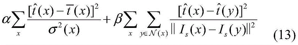
给定一个透射率的边界值

其中,α和β是控制数据项和光滑项的权重参数,σ(x)是


本发明的技术特点及效果:Technical features and effects of the present invention:
本发明方法针对水下图像增强噪声放大以及色调偏移等问题,通过把图像分成结构层和纹理层,分别进行增强和去噪,实现了提高图像对比度的同时保留好的细节,在抑制噪声的同时保持了色调的自然性。本发明具有以下特点:The method of the invention aims at the problems of noise amplification and tone shift of underwater image enhancement. By dividing the image into a structural layer and a texture layer, and performing enhancement and denoising respectively, the contrast of the image is improved while good details are preserved, and the noise is suppressed. While maintaining the naturalness of the tones. The present invention has the following characteristics:
1、本文提出的算法主要创新点是基于结构-纹理分层的思路,在两个层分别做增强和去噪处理,避免了噪声放大影响。1. The main innovation point of the algorithm proposed in this paper is based on the idea of structure-texture layering, and the two layers are enhanced and denoised respectively to avoid the influence of noise amplification.
2、本文针对色彩偏移问题提出了简单,而且普遍适用的解决方案。2. This paper proposes a simple and universally applicable solution to the color shift problem.
3、对各种不同的水下图形增强都有较好的结果,具有一定的普适性。3. It has good results for various underwater graphics enhancement, and has certain universality.
4、本文提出的算法可以应用到水下视频的增强,具有一定的扩展性。4. The algorithm proposed in this paper can be applied to the enhancement of underwater video, and has certain scalability.
附图说明Description of drawings
图1是算法框架图;Figure 1 is the algorithm framework diagram;
图2左图是捕获的水下图像,右图是对应的直方图;The left picture of Figure 2 is the captured underwater image, and the right picture is the corresponding histogram;
图3左图是色彩矫正后的图像,右图是对应的直方图;The left picture of Figure 3 is the image after color correction, and the right picture is the corresponding histogram;
图4是分解模型验证图:图4((a)合成的降质图像I;(b)是I的结构层;(c)是I的纹理层;(d)是清晰的图像J;(e)是J的结构层;(f)是J的纹理层);Figure 4 is the decomposition model verification diagram: Figure 4 ((a) synthesized degraded image I; (b) is the structural layer of I; (c) is the texture layer of I; (d) is a clear image J; (e) ) is the structural layer of J; (f) is the texture layer of J);
图5是分解结果图;Fig. 5 is the decomposition result diagram;
图6是结构层的增强结果图;Fig. 6 is the enhancement result diagram of the structural layer;
图7是纹理层的增强结果图;Fig. 7 is the enhancement result diagram of texture layer;
图8是边缘掩膜的重定义图;Figure 8 is a redefinition diagram of an edge mask;
图9是最终重构的结果图;Fig. 9 is the result picture of final reconstruction;
图10是本文和其他参考文献的效果比较图(第一栏是输入图;第二栏、第三栏和第四栏是三例现有技术的结果;第五栏是本文结果);Figure 10 is a comparison diagram of the effects of this article and other references (the first column is the input image; the second, third and fourth columns are the results of three examples of prior art; the fifth column is the results of this article);
图11是分层和不分层的增强效果图(第一行是不分层的结果图;第二行是对应分层的结果图);Figure 11 is a layered and non-layered enhancement effect map (the first row is the result map without layering; the second row is the result map corresponding to layering);
具体实施方式Detailed ways
本发明提出了基于结构-纹理分层的水下图像增强方法,将噪声残留到纹理层,没有噪声影响的结构层满足雾线模型。然后我们通过基于雾线模型增强了结构层,用梯度残留最小化方法增强纹理层。之后,通过适当的尺度伸缩,将增强后的结构层,纹理层和精细化的掩膜重构成最后的增强图。即实现在提高图像对比度的同时保留好的细节,在抑制噪声的同时保持了色调的自然性。下面结合附图和实施例对本发明作详细说明。The present invention proposes an underwater image enhancement method based on structure-texture layering, and the noise remains in the texture layer, and the structure layer without the influence of noise satisfies the fog line model. Then we enhance the texture layer by using the fog-line based model and enhance the texture layer with gradient residual minimization method. Afterwards, the enhanced structure layer, texture layer and refined mask are reconstructed into the final enhanced map through appropriate scaling. That is, to improve the contrast of the image while retaining good details, and to suppress the noise while maintaining the naturalness of the tone. The present invention will be described in detail below with reference to the accompanying drawings and embodiments.
首先,针对现存的水下图像增强方法的一些不足,我们提出一个基于分层的处理图像方法,其框架图如图1。第一步,通过直方图均衡化进行色彩校正。第二步,用TV-L1(将全变分(TV能量)作为正则项进行图像分解(称为ROF或TV-L1模型)的最优化方法)方法将图像进行分层处理,然后对结构层和纹理层分别进行增强和去噪处理。最后将增强处理后的结构层和纹理层以及精细化的掩膜重构成最终的结果图。以下是具体的实施方法:First, in view of some shortcomings of the existing underwater image enhancement methods, we propose a layer-based image processing method, the frame of which is shown in Figure 1. The first step is color correction through histogram equalization. The second step is to use TV-L 1 (the optimization method of image decomposition (called ROF or TV-L 1 model) with total variation (TV energy) as a regular term) method to stratify the image, and then to The structure layer and texture layer are respectively enhanced and denoised. Finally, the enhanced structural and texture layers and the refined mask are reconstructed into the final result map. The following is the specific implementation method:
1)对拍摄到的图像进行色彩校正。通过观察水下图像的色彩分布直方图特点如图2,1) Perform color correction on the captured image. By observing the characteristics of the color distribution histogram of the underwater image as shown in Figure 2,
8)我们看到由于在水中,不同的光段遭受不同强度的吸收和散射,仅仅在480-570波段的蓝绿光在水中衰减系数最小,穿透能力最强,所以水中捕获到的图像多呈现浅绿色光色调。为了解决这一色彩偏移问题,我们采用简单的直方图均衡化。这个原理十分直观,即将每个色彩通道的平均色彩分布移动到期望的范围,然后再进行线性归一化处理。对于每个色彩通道


其中c∈{R,G,B},μc和σc分别为每个色彩通道的平均值和标准方差。λ是一个色调参数,它有效地调节了分布范围,超出该范围的像素值将被截断。最后,这个色彩校正的图像通过最小化公式(3)得到。where c∈ {R,G,B}, μc and σc are the mean and standard deviation of each color channel, respectively. λ is a hue parameter that effectively adjusts the distribution range beyond which pixel values are truncated. Finally, this color-corrected image is obtained by minimizing equation (3).
Ic(x)=Jc(x)t(x)+Ac(1-t(x))+E(x), (4)I c (x)=J c (x)t(x)+A c (1-t(x))+E(x), (4)
其中,clip(·)是一个clip函数,它控制着将像素值范围截断到[0,255]。通过图2和图3的对比,可以说明这种方法对水下图像进行了有效的色彩纠正。where clip( ) is a clip function that controls the truncation of the pixel value range to [0, 255]. Through the comparison of Figure 2 and Figure 3, it can be shown that this method can effectively correct the color of underwater images.
2)构建分层模型。由于光路在浑浊的水中的衰减和在存在雾霾的大气中的衰减具有相似性,用何凯明的经典暗通道去雾模型来定义水下图模型:2) Build a hierarchical model. Since the attenuation of the optical path in turbid water is similar to the attenuation in the atmosphere with haze, He Kaiming's classic dark channel dehazing model is used to define the underwater graph model:
Ic(x)=Jc(x)t(x)+Ac(1-t(x))+E(x), (4)I c (x)=J c (x)t(x)+A c (1-t(x))+E(x), (4)
其中,x是像素值,Ic(x)是每个通道的色彩校正的图像,Jc(x)是恢复后的图像。Ac是全局的背景光,t(x)是水中的投射率。定义E(x)为输入图像中的噪声。图像增强的目的是从捕获到的水下图像Ic(x)恢复出Jc(x),这个过程涉及到透射率和背景光的估计where x is the pixel value, Ic (x) is the color-corrected image for each channel, and Jc (x) is the restored image. A c is the global background light, and t(x) is the transmittance in the water. Define E(x) as the noise in the input image. The purpose of image enhancement is to recover J c (x) from the captured underwater image I c (x), which involves the estimation of transmittance and background light
通常,图像在高频部分不仅包含重要的纹理信息,而且包含了大量的噪声,尤其在弱光环境中。这些因素会降低透射率估计的准确度,进而影响最终的增强效果。为了克服这个问题,先将图像分层处理,然后分别在结构层估计透射率避免噪声的影响,在纹理层单独做去噪处理。我们定义Js和Jt分别为干净图像的结构层和纹理层,然后有J=Js+Jt,那么方程(4)可以被重写为:Usually, images not only contain important texture information in high-frequency parts, but also contain a lot of noise, especially in low-light environments. These factors reduce the accuracy of the transmittance estimation, which in turn affects the final enhancement effect. In order to overcome this problem, the image is first processed in layers, and then the transmittance is estimated in the structure layer to avoid the influence of noise, and denoising is performed separately in the texture layer. We define J s and J t as the structure layer and texture layer of the clean image, respectively, and then have J = J s + J t , then equation (4) can be rewritten as:
Ic(x)=(Js c(x)+Jt c(x))t(x)+Ac(1-t(x))+E(x)I c (x)=(J s c (x)+J t c (x))t(x)+A c (1-t(x))+E(x)
=Js c(x)t(x)+Ac(1-t(x))+Jt c(x)t(x)+E(x). (5)=J s c (x)t(x)+A c (1-t(x))+J t c (x)t(x)+E(x).(5)
其中背景光Ac是光滑的信号,估计出来的透射率t也是相对光滑的,接近Js c中的理想透射率。因此,观察到的捕获图像可以被分为两层(I=Is+It),理想情况下可以得到:The background light Ac is a smooth signal, and the estimated transmittance t is also relatively smooth, close to the ideal transmittance in J sc . Therefore, the observed captured image can be divided into two layers (I = Is +It), which ideally can be obtained as:
Is c(x)=Js c(x)t(x)+Ac(1-t(x)) (6)I s c (x)=J s c (x)t(x)+A c (1-t(x)) (6)

其中,Is c是捕获图的结构层,包含着图像的大部分细节。It c是捕获图的纹理层,包含着大部分的纹理信息和噪声。通过这个方法,透射率t(x)可以从Is(x)中估计出来,免除噪声的影响。Among them, I sc is the structural layer of the captured image, which contains most of the details of the image. I t c is the texture layer of the captured image, which contains most of the texture information and noise. By this method, the transmittance t (x) can be estimated from Is (x), free from the influence of noise.
3)实现分层。由于结构层在物体的轮廓和边界具有更大的梯度,而在纹理层却具有比较小的梯度。我们用TV-L1分解模型很好地分离结构层和纹理层:3) Implement layering. Because the structure layer has a larger gradient in the contour and boundary of the object, but has a smaller gradient in the texture layer. We use the TV-L 1 decomposition model to nicely separate the structural and texture layers:

其中,
一个重要的问题是以上的TV-L1分解模型是否恰好能够按照方程(6)和方程(7)把捕获到的图分解。图4展示了一个分解例子,这个输入的图像是根据等式(4)从J合成的I,Js和Jt是用TV-L1最优化分解后的两层图像,如图所示,降质图像I(x)的结构层(Is)不包括高频纹理细节和噪声,在视觉上和原始清晰的图像的结构层是一致的。为了有更好的视觉效果,我们把纹理层放大10倍。An important question is whether the above TV - L1 decomposition model can exactly decompose the captured graphs according to Equations (6) and (7). Figure 4 shows an example of decomposition, this input image is I synthesized from J according to equation (4), J s and J t are the two-layer images decomposed with TV-L 1 optimization, as shown in the figure, The structural layer (I s ) of the degraded image I(x) excludes high-frequency texture details and noise, and is visually consistent with the structural layer of the original clear image. In order to have better visual effect, we enlarge the texture layer by 10 times.
4)背景光估计。考虑到水中光波的吸收和散射影响,我们用全局背景灯光散射估计方法对A进行了估计:4) Background light estimation. Taking into account the absorption and scattering effects of light waves in water, we estimate A using the global background light scattering estimation method:

其中,

根据暗通道先验理论,首先假设在每一个窗口内的透射率为常数,定义它为t0,A值已经由公式(9)计算出,所以我们对公式(6)两边求两次最小值运算,移项整理后,可以得到透射率t(x)的预估值:According to the dark channel prior theory, first assume that the transmittance in each window is constant, define it as t 0 , and the A value has been calculated by formula (9), so we find the minimum value twice on both sides of formula (6) After the operation, the estimated value of the transmittance t(x) can be obtained:

其中,ω是修正因子,在本文中均设置为0.95,目的是使恢复结果图更接近现实的照片。但是,仅仅用这个透射率t(x)的预估值恢复出来的结果图中存在明显的不协调部分,所以要想得到更好的增强效果,我们需要对这个预估值做精细化处理。我们观察到没有噪声的分布的Is中的像素分布符合“雾线”规律。因此,我们可以将公式(6)转化到3D坐标系当中,得出一个在三维坐标系中的透射率t'(x)(下文中称为线性透射率估计值)。把背景光A作为坐标原点,便可将公式(6)变成以下形式:Among them, ω is the correction factor, which is set to 0.95 in this paper, the purpose is to make the restoration result map closer to the realistic photo. However, there are obvious inconsistencies in the result image recovered by only using this estimated value of transmittance t(x), so in order to obtain a better enhancement effect, we need to refine this estimated value. We observe that the distribution of pixels in the Is of the distribution without noise conforms to the "fog line" law. Therefore, we can convert the formula (6) into the 3D coordinate system to obtain a transmittance t'(x) in the three-dimensional coordinate system (hereinafter referred to as the linear transmittance estimation value). Taking the background light A as the coordinate origin, the formula (6) can be transformed into the following form:
Is0(x)=t'(x)·Js0(x) (11)I s0 (x)=t'(x) · J s0 (x) (11)
其中,Is0(x)=Is(x)-A,Js0(x)=Js(x)-A。因此,我们能够根据以下公式来计算每一个像素值的线性透射率估计值:Wherein, I s0 (x)=I s (x)-A, and J s0 (x)=J s (x)-A. Therefore, we can calculate the linear transmittance estimate for each pixel value according to the following formula:

给定一个透射率的边界值

其中,α和β是控制数据项和光滑项的权重参数,σ(x)是


5)纹理层增强。通过以上TV-L1分解后,捕获图中的噪声残留在纹理层。我们用梯度残留最小化方法来增强纹理层,即增强的纹理层可以通过优化公式(15)的得到:5) Texture layer enhancement. After the above TV-L 1 decomposition, the noise in the captured image remains in the texture layer. We use the gradient residual minimization method to enhance the texture layer, that is, the enhanced texture layer can be obtained by optimizing the formula (15):

其中,δ和η是控制权重参数,控制着处理结果的光滑和精细程度,η太大或δ太小,会使得增强图像的大部分纹理随着去噪过程而丢失,所以,合适选取δ和η的值对实验结果影响很大。令Z=J-I,以上优化问题可以变成两个子问题,如下公式。Among them, δ and η are the control weight parameters, which control the smoothness and fineness of the processing results. If η is too large or δ is too small, most of the texture of the enhanced image will be lost with the denoising process. Therefore, it is appropriate to select δ and δ. The value of η has a great influence on the experimental results. Let Z=J-I, the above optimization problem can be transformed into two sub-problems, as follows.


公式(16)变成了经典的TV问题,可以参考[15]中的TV-L1方法求解。公式(17)可以用软阈值接近。Equation (16) becomes a classic TV problem, which can be solved by referring to the TV-L 1 method in [15]. Equation (17) can be approximated with a soft threshold.
6)边缘掩膜的定义。从图5中可以看出增强后的

其中,x,y是DCT中的坐标位置,我们计算除了B1,1,B1,2和B2,1的所有DCT系数的平方和,然后用阈值对每一个块的相似性进行了判断。我们定义纹理层的初始的细节掩膜为M,阈值κ为0.1,当ρ大于κ时,该块的M为1,否者,M为0.。为了得到精细化的细节掩膜

其中,m和m'是M和M'的向量表示,Ls是从Is产生的映射拉布拉氏矩阵,
7)重构图像。上面将结构层和纹理层分别进行加强,得到了边缘掩膜M,因此可以通过公式(20)重构出最终的增强处理结果:7) Reconstruct the image. The structure layer and the texture layer are strengthened respectively above, and the edge mask M is obtained, so the final enhancement processing result can be reconstructed by formula (20):

其中,τ是伸缩因子,引入了增强的细节,在实验中设为


实验中对本文算法的色彩纠正效果、分层效果、去噪效果以及增强效果做了测试,并且与对比文献的算法进行了对比,具体结果如图2、图3、图4、图5、图6、图7、图9、图10、图11所示。在图10中可以看到现有技术实例1的恢复效果放大了噪声,并且增强后图像的色调不自然。现有技术实例2的恢复结果对比度比较低,而且噪声也比较明显。现有技术实例3的处理结果在一定程度上改善了图像的对比度,减少了噪声,可是,因为该方法并不是针对水下图像增强,所以他的恢复结果存在色彩偏差,而且一些细节也没有达到很好的增强效果。图11展示了分层和不分层效果比较,可以看出增强结果丢失了一部分细节,像第一栏图中的水泡,这进一步说明基于结构-纹理分层的水下图像增强方法的效果更好。换句话说,本文提到的方法实现了最好的增强效果,不光有效地减少了噪声,而且保留了好的细节和自然的色调。In the experiment, the color correction effect, layering effect, denoising effect and enhancement effect of the algorithm in this paper were tested, and compared with the algorithm of the comparative literature. The specific results are shown in Figure 2, Figure 3, Figure 4, Figure 5, and Figure 5. 6. As shown in Figure 7, Figure 9, Figure 10, and Figure 11. It can be seen in FIG. 10 that the restoration effect of the prior art example 1 amplifies the noise, and the tone of the enhanced image is unnatural. The restoration result of the prior art example 2 has a relatively low contrast and obvious noise. The processing result of the prior art example 3 improves the contrast of the image and reduces the noise to a certain extent. However, because the method is not aimed at enhancing the underwater image, there is a color deviation in the restoration result, and some details are not up to the standard. Nice enhancement. Figure 11 shows the comparison of layered and non-layered effects. It can be seen that the enhancement result loses some details, like the water bubbles in the first column, which further shows that the underwater image enhancement method based on structure-texture layering is more effective. it is good. In other words, the method mentioned in this paper achieves the best enhancement, not only effectively reducing noise, but also preserving good details and natural tones.
Claims (3)


Priority Applications (1)
| Application Number | Priority Date | Filing Date | Title |
|---|---|---|---|
| CN201711086095.3A CN107798665B (en) | 2017-11-07 | 2017-11-07 | Underwater image enhancement method based on structure-texture layering |
Applications Claiming Priority (1)
| Application Number | Priority Date | Filing Date | Title |
|---|---|---|---|
| CN201711086095.3A CN107798665B (en) | 2017-11-07 | 2017-11-07 | Underwater image enhancement method based on structure-texture layering |
Publications (2)
| Publication Number | Publication Date |
|---|---|
| CN107798665A CN107798665A (en) | 2018-03-13 |
| CN107798665B true CN107798665B (en) | 2021-07-09 |
Family
ID=61549431
Family Applications (1)
| Application Number | Title | Priority Date | Filing Date |
|---|---|---|---|
| CN201711086095.3A Expired - Fee Related CN107798665B (en) | 2017-11-07 | 2017-11-07 | Underwater image enhancement method based on structure-texture layering |
Country Status (1)
| Country | Link |
|---|---|
| CN (1) | CN107798665B (en) |
Families Citing this family (24)
| Publication number | Priority date | Publication date | Assignee | Title |
|---|---|---|---|---|
| CN108550120B (en) * | 2018-03-29 | 2020-03-27 | 青岛大学 | A Variational Framework for Underwater Image Restoration |
| CN109118446B (en) * | 2018-07-30 | 2021-08-24 | 西南财经大学 | Underwater image restoration and denoising method |
| CN109308380B (en) * | 2018-08-24 | 2022-08-02 | 云南大学 | Embroidery artistic style simulation method based on non-photorealistic sense |
| CN109272475B (en) * | 2018-08-31 | 2022-02-18 | 深圳纳瓦科技有限公司 | Method for rapidly and effectively repairing and strengthening underwater image color |
| CN109272539A (en) * | 2018-09-13 | 2019-01-25 | 云南大学 | Decomposition method of image texture and structure based on guide graph total variation model |
| CN109816604B (en) * | 2019-01-14 | 2022-09-16 | 苏州长风航空电子有限公司 | Self-adaptive clustering infrared image enhancement method |
| CN109859129A (en) * | 2019-01-29 | 2019-06-07 | 哈工大机器人(岳阳)军民融合研究院 | A kind of underwater picture enhancing treating method and apparatus |
| CN110111261B (en) * | 2019-03-28 | 2021-05-28 | 瑞芯微电子股份有限公司 | Adaptive balance processing method for image, electronic device and computer readable storage medium |
| WO2021042270A1 (en) * | 2019-09-03 | 2021-03-11 | 中山大学 | Compression artifacts reduction method based on dual-stream multi-path recursive residual network |
| CN110634112B (en) * | 2019-10-15 | 2022-02-22 | 中国矿业大学(北京) | Method for enhancing noise-containing image under mine by double-domain decomposition |
| CN110738626B (en) * | 2019-10-24 | 2022-06-28 | 广东三维家信息科技有限公司 | Rendering graph optimization method and device and electronic equipment |
| CN111340711B (en) * | 2020-05-21 | 2020-09-08 | 腾讯科技(深圳)有限公司 | A super-resolution reconstruction method, apparatus, device and storage medium |
| CN111753896A (en) * | 2020-06-16 | 2020-10-09 | 江西中科九峰智慧医疗科技有限公司 | A classification method and system for chest X-ray exposure problem based on deep learning |
| CN112184566B (en) * | 2020-08-27 | 2023-09-01 | 北京大学 | An image processing method and system for removing attached water mist and water droplets |
| CN113012037B (en) * | 2021-03-11 | 2022-08-05 | 桂林电子科技大学 | Deep learning training data set synthesis method for underwater image restoration |
| CN113313702A (en) * | 2021-06-11 | 2021-08-27 | 南京航空航天大学 | Aerial image defogging method based on boundary constraint and color correction |
| CN114170101B (en) * | 2021-11-18 | 2025-04-04 | 重庆大学 | Weak-light image enhancement method and system based on structural texture preservation of high and low frequency information |
| CN114708352B (en) * | 2022-04-22 | 2025-05-27 | 重庆邮电大学 | A low-dose CT image restoration method and system based on unsupervised learning |
| CN115861109B (en) * | 2022-12-09 | 2026-01-27 | 北京航空航天大学 | Marine internal wave SAR image texture enhancement method, device, equipment and medium |
| CN116152116B (en) * | 2023-04-04 | 2023-07-21 | 青岛哈尔滨工程大学创新发展中心 | A method of underwater image enhancement based on visual self-attention model |
| CN118674664B (en) * | 2024-08-23 | 2024-11-29 | 浙江大华技术股份有限公司 | Image enhancement method, device and storage medium |
| CN119295360B (en) * | 2024-12-11 | 2025-06-13 | 杭州爱华仪器有限公司 | A method and device for enhancing infrared image details by reducing edge blur |
| CN120103317B (en) * | 2025-05-09 | 2025-07-18 | 广东海洋大学 | Target salvaging method for turbid water body based on artificial intelligence |
| CN120634872B (en) * | 2025-06-13 | 2026-03-17 | 东南大学南通海洋高等研究院 | Enhanced visual method for removing turbidity of turbid underwater scene |
Citations (4)
| Publication number | Priority date | Publication date | Assignee | Title |
|---|---|---|---|---|
| CN103985125A (en) * | 2014-05-19 | 2014-08-13 | 清华大学 | Complicated background SAR image naval ship tail track detection method |
| CN104458766A (en) * | 2014-12-31 | 2015-03-25 | 江南大学 | Cloth surface blemish detection method based on structure texture method |
| CN104504664A (en) * | 2014-12-29 | 2015-04-08 | 河海大学常州校区 | System and method for automatically enhancing underwater images in NSCT (non-subsampled contourlet transform) regions on basis of human visual characteristics |
| CN106897972A (en) * | 2016-12-28 | 2017-06-27 | 南京第五十五所技术开发有限公司 | A kind of self-adapting histogram underwater picture Enhancement Method of white balance and dark primary |
Family Cites Families (2)
| Publication number | Priority date | Publication date | Assignee | Title |
|---|---|---|---|---|
| US9098926B2 (en) * | 2009-02-06 | 2015-08-04 | The Hong Kong University Of Science And Technology | Generating three-dimensional façade models from images |
| CN105450923A (en) * | 2014-09-25 | 2016-03-30 | 索尼公司 | Image processing method, image processing device and electronic device |
-
2017
- 2017-11-07 CN CN201711086095.3A patent/CN107798665B/en not_active Expired - Fee Related
Patent Citations (4)
| Publication number | Priority date | Publication date | Assignee | Title |
|---|---|---|---|---|
| CN103985125A (en) * | 2014-05-19 | 2014-08-13 | 清华大学 | Complicated background SAR image naval ship tail track detection method |
| CN104504664A (en) * | 2014-12-29 | 2015-04-08 | 河海大学常州校区 | System and method for automatically enhancing underwater images in NSCT (non-subsampled contourlet transform) regions on basis of human visual characteristics |
| CN104458766A (en) * | 2014-12-31 | 2015-03-25 | 江南大学 | Cloth surface blemish detection method based on structure texture method |
| CN106897972A (en) * | 2016-12-28 | 2017-06-27 | 南京第五十五所技术开发有限公司 | A kind of self-adapting histogram underwater picture Enhancement Method of white balance and dark primary |
Non-Patent Citations (8)
| Title |
|---|
| "A Contrast Enhancement Framework with JPEG Artifacts Suppression";Li Y.等;《Computer Vision–ECCV 2014》;20141231;第174-188页 * |
| "An approach to underwater image enhancement based on image structural decomposition";Ji T.等;《Journal of Ocean University of China》;20150220;第14卷;全文 * |
| "Contrast enhancement of noisy low-light images based on structure-texture-noise decomposition";Jaemoon Lim等;《Journal of Visual Communication and Image Representation》;20170531;第45卷;全文 * |
| "Image Clarification Method Based on Structure-Texture Decomposition with Texture Refinement";Toda M.等;《Image Analysis and Processing-ICIAP 2015》;20150821;第352-362页 * |
| "Non-local Image Dehazing";D. Berman等;《2016 IEEE Conference on Computer Vision and Pattern Recognition (CVPR)》;20161212;第1674-1682页 * |
| "Robust Image and Video Dehazing with Visual Artifact Suppression via Gradient Residual Minimization";Chen C.等;《Computer Vision-ECCV 2016》;20160917;第576-591页 * |
| "TV-L1分解模型下的地震图像增强方法研究";杨宁等;《地球物理学进展》;20161215;第31卷(第6期);全文 * |
| "基于图像结构—纹理分解的医学图像去噪算法的研究";付磊;《中国优秀硕士学位论文全文数据库·信息科技辑》;20160715;第2016年卷(第7期);全文 * |
Also Published As
| Publication number | Publication date |
|---|---|
| CN107798665A (en) | 2018-03-13 |
Similar Documents
| Publication | Publication Date | Title |
|---|---|---|
| CN107798665B (en) | Underwater image enhancement method based on structure-texture layering | |
| CN107507138B (en) | An underwater image enhancement method based on Retinex model | |
| Wang et al. | Dehazing for images with large sky region | |
| CN110148095B (en) | A kind of underwater image enhancement method and enhancement device | |
| Guo et al. | LIME: Low-light image enhancement via illumination map estimation | |
| CN106157267B (en) | Image defogging transmissivity optimization method based on dark channel prior | |
| CN108734670B (en) | Restoration method of a single nighttime weak illumination haze image | |
| CN103578084B (en) | Color image enhancement method based on bright channel filtering | |
| CN101783012B (en) | An Automatic Image Dehazing Method Based on Dark Channel Color | |
| Jun et al. | Image defogging algorithm of single color image based on wavelet transform and histogram equalization | |
| CN108765342A (en) | A kind of underwater image restoration method based on improvement dark | |
| CN106204491A (en) | A kind of adapting to image defogging method based on dark channel prior | |
| CN107203977A (en) | A kind of underwater image restoration method based on dark primary priori and rarefaction representation | |
| CN111462022B (en) | Underwater image sharpness enhancement method | |
| CN115170404B (en) | Night image defogging method and device based on brightness compensation and layer separation | |
| Tao et al. | Underwater image enhancement via red channel maximum attenuation prior and multi-scale detail fusion | |
| CN117808699A (en) | Real-world single image dehazing method based on sky area segmentation and image fusion | |
| CN104978720A (en) | Video image raindrop removal method and apparatus | |
| CN105160635B (en) | A kind of image filtering method based on fractional order differential estimation gradient field | |
| CN109949244B (en) | A Variational Method for Blind Restoration of Underwater Images Based on Curvature Term | |
| CN110992287A (en) | Method for clarifying non-uniform illumination video | |
| CN108447034A (en) | A kind of marine Misty Image defogging method decomposed based on illumination | |
| CN116109513A (en) | An image defogging method based on local ambient light projection constant prior | |
| CN111028156A (en) | A Hybrid Filter Image Dehazing Algorithm Based on Dark Primitive Color Prior Model | |
| CN110660026B (en) | Image defogging method based on Retinex theory and high-saturation prior |
Legal Events
| Date | Code | Title | Description |
|---|---|---|---|
| PB01 | Publication | ||
| PB01 | Publication | ||
| SE01 | Entry into force of request for substantive examination | ||
| SE01 | Entry into force of request for substantive examination | ||
| GR01 | Patent grant | ||
| GR01 | Patent grant | ||
| CF01 | Termination of patent right due to non-payment of annual fee |
Granted publication date: 20210709 |
|
| CF01 | Termination of patent right due to non-payment of annual fee |