CN107785286B - Laser packaging method - Google Patents
Laser packaging method Download PDFInfo
- Publication number
- CN107785286B CN107785286B CN201610766719.5A CN201610766719A CN107785286B CN 107785286 B CN107785286 B CN 107785286B CN 201610766719 A CN201610766719 A CN 201610766719A CN 107785286 B CN107785286 B CN 107785286B
- Authority
- CN
- China
- Prior art keywords
- sub
- laser
- scanning
- segments
- frit
- Prior art date
- Legal status (The legal status is an assumption and is not a legal conclusion. Google has not performed a legal analysis and makes no representation as to the accuracy of the status listed.)
- Active
Links
Images


Classifications
-
- H—ELECTRICITY
- H10—SEMICONDUCTOR DEVICES; ELECTRIC SOLID-STATE DEVICES NOT OTHERWISE PROVIDED FOR
- H10K—ORGANIC ELECTRIC SOLID-STATE DEVICES
- H10K50/00—Organic light-emitting devices
- H10K50/80—Constructional details
- H10K50/84—Passivation; Containers; Encapsulations
- H10K50/842—Containers
- H10K50/8426—Peripheral sealing arrangements, e.g. adhesives, sealants
-
- H—ELECTRICITY
- H10—SEMICONDUCTOR DEVICES; ELECTRIC SOLID-STATE DEVICES NOT OTHERWISE PROVIDED FOR
- H10K—ORGANIC ELECTRIC SOLID-STATE DEVICES
- H10K71/00—Manufacture or treatment specially adapted for the organic devices covered by this subclass
-
- H—ELECTRICITY
- H10—SEMICONDUCTOR DEVICES; ELECTRIC SOLID-STATE DEVICES NOT OTHERWISE PROVIDED FOR
- H10P—GENERIC PROCESSES OR APPARATUS FOR THE MANUFACTURE OR TREATMENT OF DEVICES COVERED BY CLASS H10
- H10P72/00—Handling or holding of wafers, substrates or devices during manufacture or treatment thereof
- H10P72/04—Apparatus for manufacture or treatment
- H10P72/0431—Apparatus for thermal treatment
- H10P72/0436—Apparatus for thermal treatment mainly by radiation
-
- H—ELECTRICITY
- H10—SEMICONDUCTOR DEVICES; ELECTRIC SOLID-STATE DEVICES NOT OTHERWISE PROVIDED FOR
- H10P—GENERIC PROCESSES OR APPARATUS FOR THE MANUFACTURE OR TREATMENT OF DEVICES COVERED BY CLASS H10
- H10P72/00—Handling or holding of wafers, substrates or devices during manufacture or treatment thereof
- H10P72/04—Apparatus for manufacture or treatment
- H10P72/0441—Apparatus for sealing, encapsulating, glassing, decapsulating or the like
Landscapes
- Engineering & Computer Science (AREA)
- Manufacturing & Machinery (AREA)
- Physics & Mathematics (AREA)
- Optics & Photonics (AREA)
- Electroluminescent Light Sources (AREA)
Abstract
本发明公开了一种激光封装方法,使用激光加热位于两基底之间的玻璃料图案,所述方法包括:步骤1:对所述玻璃料图案进行路径分割,将所述玻璃料图案划分为若干子段,且相邻两子段之间具有一段重叠的区域,将该重叠的区域称为拼接区;步骤2:使用激光束对所述若干子段中一子段进行多次重复扫描,待扫描完成后移动至下一子段的起始点;步骤3:重复步骤2,直至所有玻璃料图案全部扫描完成。本发明通过采用对子段多次重复扫描,既在局部提供了准同步式的均一加热,使玻璃料能在较短的时间内达到熔融状态,又在宏观上产生了类似周线的扫描效果,使整个玻璃料先后软化封装,得到了键合比可控、封装质量较优的玻璃墙。

The invention discloses a laser encapsulation method, which uses a laser to heat a glass frit pattern located between two substrates. The method includes: step 1: dividing the glass frit pattern into a path, dividing the glass frit pattern into several sub-segments, and there is an overlapping area between two adjacent sub-segments, and the overlapping area is called a splicing area; Step 2: Use a laser beam to repeatedly scan a sub-segment of the several sub-segments, and wait for After scanning, move to the starting point of the next subsection; Step 3: Repeat Step 2 until all frit patterns are scanned. By using the repeated scanning of the sub-sections, the invention not only provides quasi-synchronized uniform heating locally, so that the glass frit can reach the molten state in a short time, but also produces a scanning effect similar to the contour line on the macroscopic level. , the whole glass frit is softened and encapsulated successively, and a glass wall with controllable bonding ratio and better encapsulation quality is obtained.
Description
技术领域technical field
本发明涉及激光封装领域,特别涉及一种激光封装方法。The invention relates to the field of laser packaging, in particular to a laser packaging method.
背景技术Background technique
光电半导体器件已广泛应用于生活的各个领域。其中,OLED(有机发光二极管)由于其良好的色彩比、宽视角、高响应速度等特点,成为了研究的热点,具有良好的应用前景。然而,OLED显示器中的电极和有机层对氧和水分十分敏感。从外界环境渗透入OLED器件内部的氧和水分会严重缩短OLED器件的寿命。因此,为OLED器件提供有效的气密式密封显得非常重要。Optoelectronic semiconductor devices have been widely used in various fields of life. Among them, OLED (Organic Light Emitting Diode) has become a research hotspot due to its good color ratio, wide viewing angle, high response speed and other characteristics, and has a good application prospect. However, the electrodes and organic layers in OLED displays are very sensitive to oxygen and moisture. Oxygen and moisture penetrating into the interior of the OLED device from the external environment can seriously shorten the lifespan of the OLED device. Therefore, it is very important to provide effective hermetic sealing for OLED devices.
近年来,一种使用玻璃料辅助激光加热的密封方法被应用于OLED显示器的密封。其中所述的玻璃料掺杂有对特定光波长具有高吸收率的材料,具有低熔点的特性。通过采用高能激光器加热并软化玻璃料,使其上有玻璃料的盖板玻璃和其上有OLED的基板玻璃之间形成气密式密封。玻璃料通常约0.7-1毫米宽,6-100微米厚。激光器输出可控的激光能量依次照射涂覆玻璃料的密封线,使所述玻璃料先后加热软化,形成气密式密封。然而,这种顺序型加热玻璃料的方式,会在玻璃料内部形成不均匀的温度分布。玻璃料内部的这种不均匀温度分布会导致裂纹、残余应力或脱层问题的产生,妨碍或削弱盖板玻璃与基板玻璃之间的气密性连接。同时,需要对密封过程的主要参数如激光功率、扫描速度等进行选择,受到这种方式的制约,限制了产率的提高。In recent years, a sealing method using frit-assisted laser heating has been applied to the sealing of OLED displays. The glass frit described therein is doped with a material with high absorption rate for a specific light wavelength, and has the characteristic of low melting point. By heating and softening the frit with a high-energy laser, a hermetic seal is formed between the cover glass with the frit and the substrate glass with the OLED thereon. The frit is typically about 0.7-1 mm wide and 6-100 microns thick. The laser energy with controllable output from the laser irradiates the sealing line coated with the glass frit in sequence, so that the glass frit is heated and softened successively to form an airtight seal. However, this sequential method of heating the frit creates an uneven temperature distribution inside the frit. This uneven temperature distribution within the frit can lead to cracks, residual stress or delamination problems, preventing or weakening the hermetic connection between the cover glass and the substrate glass. At the same time, the main parameters of the sealing process, such as laser power, scanning speed, etc., need to be selected, which is restricted by this method and limits the improvement of the yield.
现有技术中提出一种准同步扫描方式运用于激光玻璃料封装中,具有工艺区间宽,产率高,沿扫描向温度分布均匀性好等优点。然后在实际应用中,由于聚焦在玻璃料层的激光光斑的形状(圆形)、均匀性(10%-20%)等特性约束,及封装图案的尺寸大小、扫描速度存在上限等因素的影响,在按照上述方式进行扫描封装时,造成玻璃料在其内部和靠近边沿处形成密集的孔洞(气泡),对封装质量造成影响。In the prior art, a quasi-synchronous scanning method is proposed for use in laser frit encapsulation, which has the advantages of wide process interval, high yield, and good uniformity of temperature distribution along the scanning direction. Then in practical applications, due to the constraints of the shape (circle) and uniformity (10%-20%) of the laser spot focused on the frit layer, as well as the size of the package pattern, the upper limit of the scanning speed and other factors , When scanning and encapsulating in the above-mentioned manner, the glass frit will form dense holes (bubbles) in its interior and near the edge, which will affect the encapsulation quality.
发明内容SUMMARY OF THE INVENTION
本发明提供一种激光封装方法,以解决玻璃料在其内部和靠近边沿处形成密集的孔洞的问题。The invention provides a laser encapsulation method to solve the problem that the glass frit forms dense holes in the interior and near the edge.
为解决上述技术问题,本发明提供一种激光封装方法,使用激光加热位于两基底之间的玻璃料图案,使得被加热的所述玻璃料图案将所述两基底密封,所述方法包括:步骤1:对所述玻璃料图案进行路径分割,将所述玻璃料图案划分为若干子段,且相邻两子段之间具有一段重叠的区域,将该重叠的区域称为拼接区;步骤2:使用激光束对所述若干子段中一子段进行多次重复扫描,待扫描完成后移动至下一子段的起始点;步骤3:重复步骤2,直至所有玻璃料图案全部扫描完成。In order to solve the above technical problems, the present invention provides a laser encapsulation method, which uses a laser to heat a frit pattern located between two substrates, so that the heated frit pattern seals the two substrates, and the method includes the steps of: 1: Perform path segmentation on the frit pattern, divide the frit pattern into several sub-segments, and there is an overlapping area between two adjacent sub-segments, and the overlapping area is called a splicing area;
作为优选,所述若干子段的形状包括直线、圆弧和/或多条直线与圆弧的组合。Preferably, the shapes of the several sub-segments include straight lines, circular arcs and/or a combination of a plurality of straight lines and circular arcs.
作为优选,步骤1中,将所述玻璃料图案分割为若干个长度相同的子段和/或若干个长度不同的子段。Preferably, in
作为优选,所述拼接区的长度小于所述若干子段中任一子段长度的一半。Preferably, the length of the splicing region is less than half of the length of any one of the sub-segments.
作为优选,所述步骤2包括:步骤21:选取一子段为初始扫描段,计算更新所述初始扫描段的起始点和结束点的位置坐标;步骤22:对该子段进行工艺参数规划;步骤23:激光束从该子段的起始点移动至结束点;步骤24:激光束跳转至该子段的起始点,重复执行步骤23,直到跳转次数达到预设次数后执行步骤25;步骤25:计算下一扫描段的起始点和结束点的位置坐标,激光束跳转至下一扫描段的起始点;步骤26:重复步骤23-步骤25,直至所述玻璃料图案被全部扫描完成。Preferably, the
作为优选,所述步骤24、25中,激光束跳转过程中处于无输出状态。Preferably, in the steps 24 and 25, the laser beam is in a no-output state during the jumping process.
作为优选,所述步骤25中,激光束跳转前在当前子段的结束点和/或激光束在跳转后在下一子段的起始点存在时间延迟。Preferably, in the step 25, there is a time delay at the end point of the current subsection before the laser beam jumps and/or at the start point of the next subsection after the laser beam jumps.
作为优选,通过控制激光束的扫描时间、跳转时间和延迟时间,使每个子段具有相同的扫描周期。Preferably, by controlling the scanning time, jumping time and delay time of the laser beam, each subsection has the same scanning period.
作为优选,在扫描所述若干子段时,若存在特殊区域,则在扫描所述特殊区域时改变激光束的输出功率和/或扫描速度,以改变所述特殊区域获得的能量,其中所述特殊区域包括所述玻璃料图案中的圆弧段、与所述圆弧段连接的直线段以及有电极穿过的区域。Preferably, when scanning the several subsections, if there is a special area, the output power and/or scanning speed of the laser beam is changed when scanning the special area, so as to change the energy obtained by the special area, wherein the The special area includes a circular arc segment in the frit pattern, a straight line segment connected with the circular arc segment, and an area through which electrodes pass.
作为优选,所述若干子段上每个子段还设置有起始区和/或停止区,扫描所述起始区和/或停止区时改变激光束的输出功率和/或扫描速度,以改变所述起始区和/或停止区获得的能量。Preferably, each sub-segment of the several sub-segments is further provided with a start area and/or a stop area, and the output power and/or scanning speed of the laser beam are changed when scanning the start area and/or the stop area, so as to change the The energy obtained in the start zone and/or stop zone.
作为优选,所述起始区和停止区均为所述拼接区。Preferably, both the start region and the stop region are the splicing regions.
作为优选,还包括步骤4:采用自然冷却、采用激光束以预定功率曲线方式扫描玻璃料和/或采用激光束以温度反馈方式扫描玻璃料,从而对玻璃料进行冷却。Preferably, it also includes step 4: using natural cooling, using a laser beam to scan the glass frit in a predetermined power curve manner, and/or using a laser beam to scan the glass frit in a temperature feedback manner, so as to cool the glass frit.
与现有技术相比,本发明将任意长的玻璃料图案分割成较短的若干子段,对子段进行准同步扫描,由于子段的长度较短,因此能获得良好的温升,使子段具有良好的封装质量。本发明通过子段与子段之间设计拼接区,有效的解决了子段与子段间的衔接问题,使得最终能够使完整图案得到优良的封装质量,且工艺窗口较宽。并且,由于子段长度的固定,优化的工艺参数可以适用于不同尺寸的图案,也为超出扫描视场的大尺寸器件图案封装工艺奠定了基础。Compared with the prior art, the present invention divides an arbitrarily long frit pattern into several shorter sub-segments, and performs quasi-synchronous scanning on the sub-segments. Subsegments have good packaging quality. The invention effectively solves the problem of connection between the sub-sections by designing the splicing area between the sub-sections, so that the complete pattern can be finally obtained with excellent packaging quality and the process window is wider. Moreover, due to the fixed length of the sub-segment, the optimized process parameters can be applied to patterns of different sizes, which also lays a foundation for the pattern packaging process of large-size devices beyond the scanning field of view.
附图说明Description of drawings
图1a为本发明中激光扫描装置的结构示意图;Figure 1a is a schematic structural diagram of a laser scanning device in the present invention;
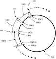
图1b为本发明中玻璃料图案的结构示意图;Figure 1b is a schematic structural diagram of a frit pattern in the present invention;
图2为本发明实施例1中激光封装方法流程图;2 is a flowchart of a laser packaging method in
图3~6为本发明实施例1中密闭玻璃料图案的扫描路径规划示意图;3 to 6 are schematic diagrams of scanning path planning of the sealed frit pattern in
图7~8为本发明实施例1中非密闭玻璃料图案的扫描路径规划示意图;7-8 are schematic diagrams of scanning path planning of the non-hermetic glass frit pattern in
图9为本发明实施例1中动态准同步扫描方法与分段准同步扫描方法的温升曲线仿真对比图;Fig. 9 is the simulation comparison diagram of the temperature rise curve of the dynamic quasi-synchronous scanning method and the segmented quasi-synchronous scanning method in
图10a~10d为本发明实施例1中单扫描周期中的功率-位置控制曲线;10a-10d are power-position control curves in a single scan cycle in
图11为本发明实施例1中密闭玻璃料图案的分段准同步扫描路径控制示意图;11 is a schematic diagram of the segmented quasi-synchronous scanning path control of the sealed frit pattern in
图12为本发明实施例1中单一子段完成封装后的玻璃料形貌俯视图;12 is a top view of the top view of the glass frit after the encapsulation of a single sub-segment in
图13为本发明实施例1中相邻子段完成封装后的玻璃料形貌的俯视图。13 is a top view of the morphology of the glass frit after the encapsulation of adjacent sub-segments in
具体实施方式Detailed ways
为使本发明的上述目的、特征和优点能够更加明显易懂,下面结合附图对本发明的具体实施方式做详细的说明。需说明的是,本发明附图均采用简化的形式且均使用非精准的比例,仅用以方便、明晰地辅助说明本发明实施例的目的。In order to make the above objects, features and advantages of the present invention more clearly understood, the specific embodiments of the present invention will be described in detail below with reference to the accompanying drawings. It should be noted that the accompanying drawings of the present invention are all in a simplified form and use inaccurate scales, and are only used to facilitate and clearly assist the purpose of explaining the embodiments of the present invention.
实施例1Example 1
本发明提供一种激光封装方法,其采用如图1a所示的激光扫描装置,该激光扫描装置包括:控制器模块110、激光扫描模块111、激光器模块112以及温度监控模块113,其中,所述控制器模块100分别与所述激光扫描模块111、激光器模块112以及温度监控模块113连接,用于控制激光器模块112及所述激光扫描模块111以及扫描温度,所述激光器模块112与激光扫描模块111相连,所述激光器模块111用于生成激光,以预定功率将激光发送至所述激光扫描模块111,所述激光扫描模块111用于改变激光传送方向及运动特征,所述温度监控模块113用于监控激光的扫描温度。进一步的,该激光扫描装置还包括一计算机114,所述计算机114与所述控制器模块110相连,用于与所述控制器模块110进行数据交换。The present invention provides a laser packaging method, which adopts a laser scanning device as shown in FIG. 1a, the laser scanning device includes: a
本实施例用于对OLED显示器120采用玻璃料形成气密式密封,其中,OLED显示器120是典型的玻璃封装体,所述OLED显示器120其主要结构包括盖板玻璃121、玻璃料122、基板玻璃123、OLED层125和电极124。其中,所述玻璃料122位于OLED显示器120的基板玻璃123上,其俯视图如图1b所示。所述玻璃料122通过丝网印刷、预烧结步骤预固化在基板玻璃123上,形成具有一定厚度的圆角矩形密封线。基板玻璃123上的OLED层125位于玻璃料122密封线的内侧,同时基板玻璃123上存在连接OLED显示器120内外部的电极124。This embodiment is used to form an airtight seal with glass frit for the
如图2所示,本发明提供一种激光封装方法,使用激光加热位于两基底玻璃123之间的玻璃料122图案,使得被加热的所述玻璃料122图案将所述两基底玻璃123密封,其具体包括:As shown in FIG. 2, the present invention provides a laser encapsulation method, which uses a laser to heat a pattern of frit 122 located between two
步骤1:如图3至图8所示,对待扫描的玻璃料122图案进行路径分割,将玻璃料122图案划分为若干子段132,且相邻两子段132之间具有一段重叠的区域,将该重叠的区域称为拼接区131。具体地,所述子段132可以是一条直线或圆弧,也可以是多条直线或圆弧的组合。所述子段132的长度L132是指沿玻璃料122图案宽度对称的中心线方向上的累计长度,包括直线段和圆弧段的长度之和。通常,取L132<=30mm。Step 1: As shown in FIG. 3 to FIG. 8 , the pattern of the frit 122 to be scanned is divided into paths, and the pattern of the frit 122 is divided into
进一步的,所述子段132具有两个端点即分别为起始点133和接束点134。其中,132(k)代表第k段子段132,取1~N,N为分割后子段132的总数,133(k)和134(k)则分别代表第k个子段132的起始点和结束点。Further, the sub-segment 132 has two end points, namely, the
所述拼接区131为前一子段132(k)的结束点134(k)与后一子段132(K+1)的起始点133(k+1)之间的区域,其具有一定的长度L131,其中L131<L132/2。进一步的,一般取L131<=2mm。The
需要说明的是,可以将玻璃料122图案分割为若干等长的子段132,如图3、5、7所示;当然,也可以将玻璃料122图案分割成若干个长度近似相同的子段132和一个长度略短或略长的子段132组成,当然,此处的略短和较长为相对于其他子段132而言,如图4所示。更进一步的,还可以将玻璃料122图案分割成若干个长度近似相同的子段132和若干长度不同的子段132组成。It should be noted that the pattern of the frit 122 can be divided into
当然,本实施例中的玻璃料122图案,可以是密闭图案,如图3和图4所示的圆角矩形,如图5所示的圆形以及如图6所示的椭圆形。也可以是非密闭图案,如图7和图8所示直线图案。Of course, the pattern of the
步骤2:使用激光束对子段132进行多次重复扫描,待扫描完成后移动至下一子段132的起始点。具体地,该步骤2包括:Step 2: Use the laser beam to repeatedly scan the
步骤21:选取一子段132为初始扫描段,计算更新所述初始扫描段的起始点133和结束点134的位置坐标;通常激光束会从按照序号递增的顺序进行扫描。然而,对于任意形状的密闭图案,激光束可以从任意序号的子段132开始进行扫描,而对于非密闭图案,则通常选取玻璃料122一端的子段132作为初始扫描段。Step 21 : Select a
步骤22:对该子段132进行工艺参数规划;该工艺参数具体包括当前子段132的速度、功率和轨迹,并且当玻璃料122具有相同或近似的印刷与预烧结工艺时,其实施的工艺参数可以是一致的,使得已知的工艺参数可以方便的应用至封装不同尺寸的玻璃料122上;Step 22: Planning the process parameters for the
步骤23:激光束从该子段132的起始点133移动至结束点134;Step 23: the laser beam is moved from the
步骤24:激光束跳转至该子段132的起始点133,重复执行步骤23,直到跳转次数达到预设次数后执行步骤25;Step 24: the laser beam jumps to the
步骤25:计算下一子段132的起始点133和结束点134的位置坐标,激光束跳转至下一子段132的起始点133;Step 25: Calculate the position coordinates of the
步骤26:重复步骤23-步骤25,直至所述玻璃料图案被全部扫描完成。Step 26: Repeat steps 23-25 until all the frit patterns are scanned.
具体地,控制器模块110控制激光扫描模块111,将激光束投射至当前子段132的起始点133(k),控制激光器按较高的功率输出激光能量P,同时控制激光束以较高的速度移动Vscan、扫描当前子段132,扫描方向由起始点133(k)指向结束点134(k)。当激光束扫描至结束点134(k)时,停止激光能量的输出并控制激光束以更高的速度Vjump跳转至起始点133(k)。较佳的,在激光束跳转的前后,可以存在一定时间的延迟,即激光光束保持停留在起始点133(k)或结束点134(k)一定时间tdelay,并处于无激光输出的状态。激光输出的时间段,称为扫描阶段,激光未输出的时间段,称为跳转阶段,扫描阶段加上跳转阶段称为子段封装的一个扫描周期。Specifically, the
重复多个所述的单个扫描周期,直至玻璃料122加热软化并完成所需质量的连接,完成当前子端132封装所需的单个扫描周期的数量称为子段扫描次数M。利用多个单个扫描周期的激光扫描,使当前子段132的玻璃料122获得足够的能量,将所属两块玻璃基板连接在一起,形成局部气密式的密封连接;所述的足够的能量可以表现为玻璃料122温度达到并超过其软化点(熔点)。所述多个扫描周期的激光扫描,可以是针对每一次扫描周期采用相同的功率曲线,使玻璃料122以一种温升逐渐减小的温度曲线来加热,通过增加扫描次数,来达到目标温度。在所述的单个扫描周期内,玻璃料122吸收激光能量后被依次被加热,每个子段132的玻璃料被多次加热。由于子段132的长度L132被约束在一个较小的值内(<=30mm),因此相较以往采用的准同步方案,对于相同的扫描速度、功率、扫描次数和光斑形貌,采用分段准同步方式时,当前子段132上固定位置被光束照射加热的间隔更短,因此拥有更好的温升效应,仿真的温度曲线如图9所示。A plurality of the single scanning cycles are repeated until the
步骤3:重复步骤2,直至所有玻璃料122图案全部扫描完成,较佳的,本步骤是通过对当前扫描次数与预定的总扫描次数进行比对,确定是否完成全部扫描,若是结束扫描,若否返回步骤2。Step 3:
进一步的,本发明可以在单一子段132内,根据实际需要(例如激光功率需要调整时),设置起始区、停止区以及其他的预设区如电极覆盖区域。本实施例的起始区和停止区也可以设置在拼接区131内,即与拼接区131重合。在上述各区域内,通过控制器模块110控制激光器模块112和激光扫描模块111,使激光的移动扫描操作和激光功率调整操作同步,即激光束可以在上述区域内可以线性或非线性的改变激光输出功率和/或激光扫描速度,进而使得子段132内除上述区域外的其它区域可以获得相对均匀的能量,而在起始区、停止区以及预设区的位置上,可以获得不同于上述其他区域的相对均匀的能量,也可以获得不同于上述其他区域的相对不均匀的能量,进而对有电极或其他器件穿过的子段132区域,进行扫描。Further, the present invention can set a start area, a stop area, and other preset areas such as electrode coverage areas in a
如图10a至图10d所示,其中,图10a~图10b分别为单扫描周期中同时设置起始区、停止区以及电极覆盖区域的功率-位置控制曲线;图10c为只设置停止区和电极覆盖区域的功率-位置控制曲线;图10d为只设置起始区和电极覆盖区域的功率-位置控制曲线。As shown in Fig. 10a to Fig. 10d, Fig. 10a to Fig. 10b are the power-position control curves in which the start area, the stop area and the electrode coverage area are set at the same time in a single scan cycle respectively; Fig. 10c shows that only the stop area and the electrode are set The power-position control curve of the coverage area; Figure 10d shows the power-position control curve with only the starting area and the electrode coverage area set.
进一步的,本发明还包括步骤4:冷却玻璃料122。本发明中存在两种冷却方式,一种是:在玻璃料122吸收足够能量后,关闭激光输出,使玻璃料122自然冷却,由于玻璃料122是近似同步加热的,因此其冷却速率相对顺序型更为缓和;另一种冷却方式是:仍然重复扫描周期,通过预定功率曲线方式或温度反馈方式,以较低的激光功率扫描玻璃料122,使玻璃料122按照预定的冷却曲线进行冷却。所述的冷却曲线具有缓和的冷却速率,因此可以较好的较小冷却过程中产生的热应力。当然,所述的控制玻璃料122冷却的方式可以是对玻璃料122冷却全过程的控制,也可以是针对玻璃料122在自然冷却过程中某一段冷却速率较快的部分进行控制,而其余时间部分则采用自然冷却。Further, the present invention further includes step 4: cooling the
如图11所示,为将带封装的玻璃料122图案进行动态扫描路径规划,将带封装的玻璃料122图案分割为长度相等的若干个子段132,此处子段132长为29mm,则得到4个子段132,拼接区131的长度为1mm;As shown in FIG. 11 , in order to carry out dynamic scanning path planning for the encapsulated
选取子段132(1)开始封装,将激光束输出115~130W功率以匀速4m/s由起始点133(1)扫描向结束点134(1),功率-位置控制曲线如图10b所示,然后关闭激光输出,以8m/s的速度跳转至起始点133(1);重复进行40次,对于覆盖圆角图案的子段,对圆角区采用区别于直线区的功率,一般的,将入圆角前0.1mm及出圆角0.1mm的直线区域纳入圆角区,使用的激光功率为105~110W;Select subsection 132(1) to start packaging, and output 115-130W of laser beam power to scan from the starting point 133(1) to the ending point 134(1) at a constant speed of 4m/s. The power-position control curve is shown in Figure 10b. Then turn off the laser output, jump to the starting point 133 (1) at a speed of 8m/s; repeat 40 times, for the subsection covering the rounded corner pattern, use a power different from the linear area for the rounded corner area. Generally, The straight line area of 0.1mm before entering the fillet and 0.1mm leaving the fillet is included in the fillet area, and the laser power used is 105-110W;
接着。沿顺时针方向,选择子段132(2)进行封装。控制激光光斑预定位置跳转至端点133(2),参照步骤2~3完成封装;以此类推,完成所有子段132的封装,其扫描路径控制如图11所示。then. Clockwise, subsection 132(2) is selected for packaging. The predetermined position of the laser spot is controlled to jump to the end point 133 (2), and the encapsulation is completed by referring to
需要说明的是,本实施例使用激光多次照射扫描某一子段132,使当前子段132上各处的玻璃料122温度升高,直至获得足够的能量使玻璃料122熔融软化,最终使该子段132的非拼接区的部分所对应的上下玻璃基板连接在一起,形成局部均一致密的玻璃墙。该过程称为子段封装。对于子段封装形成的玻璃墙的特征展开描述如下:It should be noted that in this embodiment, a
1、该子段132的非拼接区域在封装后形成沿玻璃料宽度方向的颜色和形貌等相同的已封装区域201、或者分为已封装区域201和未封装区域203,其中,将上下玻璃基板连接起来的致密均一的已封装区域201占据了大部分区域,该部分区域的宽度>85%的玻璃料122图案的总宽度,如图12所示。1. After encapsulation, the non-splicing area of the
2、该子段132的拼接区域在封装后形成沿玻璃料122宽度方向的颜色和形貌等相同的已封装区域201、或颜色或形貌等不相同的至少两个部分,该两部分分别为拼接封装区域202和未封装区域203。2. After encapsulation, the splicing area of the sub-section 132 forms the encapsulated
其中,当该子段132的相邻子段132未实施子段封装时,则该侧的拼接封装区域202的宽度应明显小于已封装区域201的宽度;当该子段132的相邻子段已实施子段封装时,则该侧的拼接封装区域202的宽度应与已封装区域201的宽度相同或接近。Wherein, when the
使用激光依次对其它子段132实施子段封装,使其它子段132先后完成加热和熔融软化,最终,使整个玻璃料122图案都完成封装,形成完整、均一、致密的玻璃墙,以实现气密式密封。The
对于子段封装中的单个扫描周期,其消耗的总时间称为单扫描周期时间tonescan,可以由以下公式近似计算得到:For a single scan cycle in the sub-segment encapsulation, the total time it consumes is called the single scan cycle time tonescan , which can be approximately calculated by the following formula:

本实施例中,任意子段132(k)的任意单个扫描周期的时间tonescan(k)均相等。In this embodiment, the time t onescan (k) of any single scan period of any subsection 132(k) is equal.
即:对于单个子段132(k),其任意单个扫描周期时间tonescan(k)均应相等;对于不同的子段132(k)和子段132(j),其单个扫描周期时间tonescan应满足:That is: for a single subsection 132(k), any single scan cycle time tonescan (k) should be equal; for different subsections 132(k) and 132(j), its single scan cycle time toonescan should be Satisfy:
tonescan(k)≈tonescan(j) t onescan(k) ≈t onescan(j)
具体地,当玻璃料122图案被分割成若干登场的子段132时,其扫描速度Vscan始终是一恒定值,跳转速度Vjump也是一恒定值,为获得最短的但扫描周期时间,取延时时间tdelay为0,则单个扫描周期的时间应由下式近似计算获得:Specifically, when the frit 122 pattern is divided into

当玻璃料122图案被分割成若干个长度近似相同的子段132(1)~132(N-1)和一个长度略短的子段132(N)时,对于子段132(1)~132(N-1),仍取tdelay为0,单个扫描周期的时间通过下式计算:When the frit 122 pattern is divided into several sub-segments 132(1)-132(N-1) with approximately the same length and a sub-segment 132(N) with a slightly shorter length, for the sub-segments 132(1)-132 (N-1), still take t delay as 0, the time of a single scan cycle is calculated by the following formula:

对于子段132(N),可以调整跳转速度与延迟时间来保证单个扫描周期的时间一致,该子段的跳转速度和延迟时间应满足:For subsection 132(N), the jump speed and delay time can be adjusted to ensure that the time of a single scan cycle is consistent. The jump speed and delay time of this subsection should satisfy:

当玻璃料122图案被分割成若干个长度各不相同的子段132时,则任意两个子段132(k)与子段132(j)应满足:When the frit 122 pattern is divided into

实施例2Example 2
本实施例与实施例1的区别在于,本实施例采用振镜作为激光扫描装置。由于振镜的视场存在大小约束,因此,在进行激光扫描过程中需要确定振镜扫描视场。其实际应用时,步骤如下:The difference between this embodiment and
将带封装的玻璃料122图案分割长度相等的若干个子段132,取子段132长为29mm,得到N个子段132,拼接区131的长度为1mm;Divide the encapsulated
将振镜移动至子段132(1)上方,使振镜的扫描视场尽可能多的覆盖相连接的子段132;Move the galvanometer to the top of the subsection 132(1), so that the scanning field of view of the galvanometer covers the
选取子段132(1)开始封装,将激光束输出115~130W功率以匀速4m/s由始点133(1)扫描向结束点134(1),功率曲线如图10b,然后关闭激光输出,以8m/s的速度跳转至起始点133(1);重复进行40次,对于覆盖圆角图案的子段132,对圆角区采用区别于直线区的功率,一般的,将入圆角前0.1mm及出圆角0.1mm的直线区域纳入圆角区,使用的激光功率为105~110W;Select subsection 132(1) to start packaging, and scan the laser beam output power of 115-130W at a constant speed of 4m/s from the start point 133(1) to the end point 134(1). The speed of 8m/s jumps to the starting point 133 (1); repeats 40 times, for the
在振镜扫描视场内,沿顺时针方向,选择子段132(2)进行封装。Within the scanning field of view of the galvanometer, in a clockwise direction, subsection 132(2) is selected for packaging.
以此类推,完成当前振镜扫描视场内所有子段132的激光扫描封装后,将振镜移动至下一个位置,所述位置能够极可能多的覆盖与最近一次完成扫描封装的子段132相邻的待扫描的子段132,完成当前扫描视场内的所有子段132的扫描封装;以此类推,完成所有子段132的封装。By analogy, after completing the laser scanning encapsulation of all
显然,本领域的技术人员可以对发明进行各种改动和变型而不脱离本发明的精神和范围。这样,倘若本发明的这些修改和变型属于本发明权利要求及其等同技术的范围之内,则本发明也意图包括这些改动和变型在内。Obviously, those skilled in the art can make various changes and modifications to the invention without departing from the spirit and scope of the invention. Thus, provided that these modifications and variations of the present invention fall within the scope of the claims of the present invention and their equivalents, the present invention is also intended to include such modifications and variations.
Claims (13)
Priority Applications (1)
| Application Number | Priority Date | Filing Date | Title |
|---|---|---|---|
| CN201610766719.5A CN107785286B (en) | 2016-08-30 | 2016-08-30 | Laser packaging method |
Applications Claiming Priority (1)
| Application Number | Priority Date | Filing Date | Title |
|---|---|---|---|
| CN201610766719.5A CN107785286B (en) | 2016-08-30 | 2016-08-30 | Laser packaging method |
Publications (2)
| Publication Number | Publication Date |
|---|---|
| CN107785286A CN107785286A (en) | 2018-03-09 |
| CN107785286B true CN107785286B (en) | 2020-12-04 |
Family
ID=61449559
Family Applications (1)
| Application Number | Title | Priority Date | Filing Date |
|---|---|---|---|
| CN201610766719.5A Active CN107785286B (en) | 2016-08-30 | 2016-08-30 | Laser packaging method |
Country Status (1)
| Country | Link |
|---|---|
| CN (1) | CN107785286B (en) |
Families Citing this family (3)
| Publication number | Priority date | Publication date | Assignee | Title |
|---|---|---|---|---|
| KR102580292B1 (en) * | 2018-05-29 | 2023-09-19 | 삼성디스플레이 주식회사 | Display device, method for fabricating the device and laser processing apparatus for fabricating the device |
| CN111400989B (en) * | 2018-12-29 | 2022-06-17 | 上海微电子装备(集团)股份有限公司 | Laser packaging path obtaining method, laser packaging method and laser packaging system |
| CN112018269B (en) * | 2019-05-31 | 2021-11-12 | 上海微电子装备(集团)股份有限公司 | Laser packaging method |
Citations (3)
| Publication number | Priority date | Publication date | Assignee | Title |
|---|---|---|---|---|
| CN102157704A (en) * | 2011-03-11 | 2011-08-17 | 上海大学 | Light sources for lighting organic electroluminescence (OEL) plants and manufacturing method thereof |
| KR101071166B1 (en) * | 2011-04-22 | 2011-10-10 | 주식회사 엘티에스 | Method for sealing frit using laser |
| CN103531726A (en) * | 2013-10-25 | 2014-01-22 | 上海大学 | Laser bonding method |
Family Cites Families (4)
| Publication number | Priority date | Publication date | Assignee | Title |
|---|---|---|---|---|
| US7208395B2 (en) * | 2003-06-26 | 2007-04-24 | Semiconductor Energy Laboratory Co., Ltd. | Laser irradiation apparatus, laser irradiation method, and method for manufacturing semiconductor device |
| KR100688796B1 (en) * | 2006-01-25 | 2007-03-02 | 삼성에스디아이 주식회사 | Organic light emitting display device and manufacturing method thereof |
| WO2013042337A1 (en) * | 2011-09-20 | 2013-03-28 | パナソニック株式会社 | Optical fiber, fiber laser employing same, and optical fiber manufacturing method |
| CN103367658B (en) * | 2013-07-17 | 2016-08-31 | 深圳市华星光电技术有限公司 | A kind of glass package structure and method for packing |
-
2016
- 2016-08-30 CN CN201610766719.5A patent/CN107785286B/en active Active
Patent Citations (3)
| Publication number | Priority date | Publication date | Assignee | Title |
|---|---|---|---|---|
| CN102157704A (en) * | 2011-03-11 | 2011-08-17 | 上海大学 | Light sources for lighting organic electroluminescence (OEL) plants and manufacturing method thereof |
| KR101071166B1 (en) * | 2011-04-22 | 2011-10-10 | 주식회사 엘티에스 | Method for sealing frit using laser |
| CN103531726A (en) * | 2013-10-25 | 2014-01-22 | 上海大学 | Laser bonding method |
Also Published As
| Publication number | Publication date |
|---|---|
| CN107785286A (en) | 2018-03-09 |
Similar Documents
| Publication | Publication Date | Title |
|---|---|---|
| KR101117732B1 (en) | Laser beam irradiation apparatus for substrate sealing and manufacturing method of organic light emitting display device using the same | |
| JP6374093B2 (en) | Laser packaging system and method | |
| JP5127465B2 (en) | Sealed glass package and manufacturing method thereof | |
| JP4809368B2 (en) | System and method for frit sealing a glass package | |
| JP6120917B2 (en) | Laser beam irradiation apparatus used for substrate sealing, substrate sealing method, and organic light emitting display device manufacturing method | |
| CN104466033B (en) | A kind of laser sintered equipment and sintering method | |
| KR102117608B1 (en) | Sealing apparatus, substrate sealing apparatus comprising the same and substrate sealing method | |
| TWI623120B (en) | Laser sealed glass package packaging system and packaging method | |
| CN107785286B (en) | Laser packaging method | |
| CN105226204A (en) | A kind of laser package equipment and method for packing | |
| CN106607645A (en) | Laser packaging system and method for temperature control in laser packaging process | |
| CN107785499B (en) | Laser packaging method | |
| CN106299157A (en) | A kind of LASER HEATING package system and method | |
| CN204289543U (en) | A kind of laser sintered equipment | |
| CN107331796A (en) | The method for packing of laser scanning seal glass packaging body |
Legal Events
| Date | Code | Title | Description |
|---|---|---|---|
| PB01 | Publication | ||
| PB01 | Publication | ||
| SE01 | Entry into force of request for substantive examination | ||
| SE01 | Entry into force of request for substantive examination | ||
| GR01 | Patent grant | ||
| GR01 | Patent grant | ||
| TR01 | Transfer of patent right |
Effective date of registration: 20250912 Address after: 3 / F, building 19, building 8, No. 498, GuoShouJing Road, China (Shanghai) pilot Free Trade Zone, Pudong New Area, Shanghai, 201203 Patentee after: Shanghai Xinshang Microelectronics Technology Co.,Ltd. Country or region after: China Address before: 201203 Pudong New Area East Road, No. 1525, Shanghai Patentee before: SHANGHAI MICRO ELECTRONICS EQUIPMENT (GROUP) Co.,Ltd. Country or region before: China |
|
| TR01 | Transfer of patent right |