CN107734692B - Method and apparatus for allocating data channel resources in a wireless communication system - Google Patents
Method and apparatus for allocating data channel resources in a wireless communication system Download PDFInfo
- Publication number
- CN107734692B CN107734692B CN201710675075.3A CN201710675075A CN107734692B CN 107734692 B CN107734692 B CN 107734692B CN 201710675075 A CN201710675075 A CN 201710675075A CN 107734692 B CN107734692 B CN 107734692B
- Authority
- CN
- China
- Prior art keywords
- configuring
- data channel
- downlink control
- control information
- system bandwidth
- Prior art date
- Legal status (The legal status is an assumption and is not a legal conclusion. Google has not performed a legal analysis and makes no representation as to the accuracy of the status listed.)
- Active
Links
- 238000000034 method Methods 0.000 title claims abstract description 78
- 238000004891 communication Methods 0.000 title claims abstract description 42
- 238000013468 resource allocation Methods 0.000 claims abstract description 66
- 230000005540 biological transmission Effects 0.000 claims description 68
- 239000010410 layer Substances 0.000 description 17
- 230000002776 aggregation Effects 0.000 description 12
- 238000004220 aggregation Methods 0.000 description 12
- 230000011664 signaling Effects 0.000 description 7
- 238000010295 mobile communication Methods 0.000 description 6
- 230000008569 process Effects 0.000 description 5
- 101100411667 Arabidopsis thaliana RAN4 gene Proteins 0.000 description 4
- 239000013256 coordination polymer Substances 0.000 description 4
- 238000005516 engineering process Methods 0.000 description 4
- 101150069124 RAN1 gene Proteins 0.000 description 3
- 101100355633 Salmo salar ran gene Proteins 0.000 description 3
- 238000005259 measurement Methods 0.000 description 3
- 101150014328 RAN2 gene Proteins 0.000 description 2
- 230000006872 improvement Effects 0.000 description 2
- 230000000977 initiatory effect Effects 0.000 description 2
- 238000012423 maintenance Methods 0.000 description 2
- 238000013507 mapping Methods 0.000 description 2
- 239000000203 mixture Substances 0.000 description 2
- 238000012544 monitoring process Methods 0.000 description 2
- 208000036357 GUCY2D-related recessive retinopathy Diseases 0.000 description 1
- 230000001174 ascending effect Effects 0.000 description 1
- 230000023402 cell communication Effects 0.000 description 1
- 230000001413 cellular effect Effects 0.000 description 1
- 230000008859 change Effects 0.000 description 1
- 238000006243 chemical reaction Methods 0.000 description 1
- 150000001875 compounds Chemical class 0.000 description 1
- 230000036541 health Effects 0.000 description 1
- 230000004807 localization Effects 0.000 description 1
- 238000012986 modification Methods 0.000 description 1
- 230000004048 modification Effects 0.000 description 1
- 238000012806 monitoring device Methods 0.000 description 1
- 230000003287 optical effect Effects 0.000 description 1
- 239000013307 optical fiber Substances 0.000 description 1
- 239000011541 reaction mixture Substances 0.000 description 1
- 230000008054 signal transmission Effects 0.000 description 1
- 239000002356 single layer Substances 0.000 description 1
- 238000000638 solvent extraction Methods 0.000 description 1
- 238000006467 substitution reaction Methods 0.000 description 1
- 230000001360 synchronised effect Effects 0.000 description 1
- 238000012360 testing method Methods 0.000 description 1
Images


Classifications
-
- H—ELECTRICITY
- H04—ELECTRIC COMMUNICATION TECHNIQUE
- H04L—TRANSMISSION OF DIGITAL INFORMATION, e.g. TELEGRAPHIC COMMUNICATION
- H04L5/00—Arrangements affording multiple use of the transmission path
- H04L5/003—Arrangements for allocating sub-channels of the transmission path
- H04L5/0044—Allocation of payload; Allocation of data channels, e.g. PDSCH or PUSCH
-
- H—ELECTRICITY
- H04—ELECTRIC COMMUNICATION TECHNIQUE
- H04W—WIRELESS COMMUNICATION NETWORKS
- H04W72/00—Local resource management
- H04W72/20—Control channels or signalling for resource management
- H04W72/23—Control channels or signalling for resource management in the downlink direction of a wireless link, i.e. towards a terminal
-
- H—ELECTRICITY
- H04—ELECTRIC COMMUNICATION TECHNIQUE
- H04L—TRANSMISSION OF DIGITAL INFORMATION, e.g. TELEGRAPHIC COMMUNICATION
- H04L1/00—Arrangements for detecting or preventing errors in the information received
- H04L1/12—Arrangements for detecting or preventing errors in the information received by using return channel
- H04L1/16—Arrangements for detecting or preventing errors in the information received by using return channel in which the return channel carries supervisory signals, e.g. repetition request signals
- H04L1/18—Automatic repetition systems, e.g. Van Duuren systems
- H04L1/1829—Arrangements specially adapted for the receiver end
- H04L1/1861—Physical mapping arrangements
-
- H—ELECTRICITY
- H04—ELECTRIC COMMUNICATION TECHNIQUE
- H04L—TRANSMISSION OF DIGITAL INFORMATION, e.g. TELEGRAPHIC COMMUNICATION
- H04L5/00—Arrangements affording multiple use of the transmission path
- H04L5/003—Arrangements for allocating sub-channels of the transmission path
- H04L5/0053—Allocation of signalling, i.e. of overhead other than pilot signals
-
- H—ELECTRICITY
- H04—ELECTRIC COMMUNICATION TECHNIQUE
- H04L—TRANSMISSION OF DIGITAL INFORMATION, e.g. TELEGRAPHIC COMMUNICATION
- H04L5/00—Arrangements affording multiple use of the transmission path
- H04L5/0091—Signalling for the administration of the divided path, e.g. signalling of configuration information
-
- H—ELECTRICITY
- H04—ELECTRIC COMMUNICATION TECHNIQUE
- H04L—TRANSMISSION OF DIGITAL INFORMATION, e.g. TELEGRAPHIC COMMUNICATION
- H04L5/00—Arrangements affording multiple use of the transmission path
- H04L5/0091—Signalling for the administration of the divided path, e.g. signalling of configuration information
- H04L5/0092—Indication of how the channel is divided
-
- H—ELECTRICITY
- H04—ELECTRIC COMMUNICATION TECHNIQUE
- H04W—WIRELESS COMMUNICATION NETWORKS
- H04W72/00—Local resource management
- H04W72/04—Wireless resource allocation
- H04W72/044—Wireless resource allocation based on the type of the allocated resource
- H04W72/0446—Resources in time domain, e.g. slots or frames
-
- H—ELECTRICITY
- H04—ELECTRIC COMMUNICATION TECHNIQUE
- H04W—WIRELESS COMMUNICATION NETWORKS
- H04W72/00—Local resource management
- H04W72/20—Control channels or signalling for resource management
-
- H—ELECTRICITY
- H04—ELECTRIC COMMUNICATION TECHNIQUE
- H04W—WIRELESS COMMUNICATION NETWORKS
- H04W72/00—Local resource management
- H04W72/12—Wireless traffic scheduling
Landscapes
- Engineering & Computer Science (AREA)
- Signal Processing (AREA)
- Computer Networks & Wireless Communication (AREA)
- Mobile Radio Communication Systems (AREA)
Abstract
The invention discloses a method and a device for allocating data channel resources in a wireless communication system. The present exemplary embodiment proposes an uplink data channel/downlink data channel (i.e., PDSCH and PUSCH) resource allocation method for a Machine Type Communication (MTC) terminal in a 3GPP LTE/LTE-a system and a Downlink Control Information (DCI) configuration method therefor. Specifically, the present exemplary embodiment proposes an uplink/downlink data channel resource allocation method for an MTC terminal further enhanced to support enhanced uplink/downlink data channel (i.e., PDSCH and PUSCH) bandwidths as compared to the MTC terminal (BL/CE UE) defined in LTE release-13.
Description
Cross Reference to Related Applications
The present application claims priority from korean patent application nos. 10-2016-0102627 and 10-2017-0065832, filed on 8/11/2016 and 29/5/2017, respectively, which are incorporated herein by reference for all purposes as if fully set forth herein.
Technical Field
The present exemplary embodiments relate to a method and apparatus for allocating uplink/downlink data channel resources in a wireless communication system.
Background
With the expansion of LTE/LTE-a networks, mobile communication service providers want to minimize the number of Radio Access Terminals (RATs) to reduce network maintenance costs. However, as related art Machine Type Communication (MTC) products based on GSM/GPRS networks increase, there is a problem in that a mobile communication service provider needs to separately operate two RATs to use an LTE/LTE-a network for general data transmission and a GSM/GPRS network for MTC.
Therefore, in order to reduce the unit price of a terminal compared to an existing general LTE terminal, in consideration of MTC application scenarios, such as a reduced-bandwidth low-complexity user equipment (BL UE) in which the transmission/reception bandwidth of the terminal is limited to six PRBs (physical resource blocks) and the number of transmission/reception antennas is limited to one or a smart meter installed in a "deep indoor" environment such as a basement, a Coverage Enhancement (CE) mode is defined as a CE UE, and a standard technology for supporting the BL/CE UE is defined in 3GPP release-13.
Further enhancements for BL/CE UEs as defined in 3GPP release-13 will be discussed in 3GPP release-14.
In this case, a UE required to have an enhanced data rate than an existing 3GPP release-13 BL/CE UE supports a PDSCH and a PUSCH transmission/reception bandwidth extended to exceed a narrowband defined as 6PRB size based on a maximum transmission/reception bandwidth of the existing 3GPP release-13 BL/CE UE. Therefore, it is difficult to reuse the resource allocation method and DCI format for 3GPP release-13 BL/CE UEs.
Disclosure of Invention
An aspect of the present exemplary embodiment is to provide a data channel resource allocation method and DCI format for a BL/CE UE when the BL/CE UE defined in 3GPP release-13 supports an extended data transmission/reception bandwidth.
According to an aspect of the present exemplary embodiment, there is provided a method for allocating data channel resources in a wireless communication system, including: configuring a narrowband defined as six consecutive physical resource blocks configuring a system bandwidth; allocating one or more narrow bands among the configured narrow bands to transmit/receive a data channel; and transmitting information indicating the allocated one or more narrowbands through the downlink control information.
According to another aspect of the present exemplary embodiment, there is provided a method for listening to data channel resource allocation in a wireless communication system, comprising: receiving downlink control information from a base station; identifying one or more narrow bands allocated for transmitting/receiving a data channel through the downlink control information; and transmitting/receiving data channels through one or more allocated narrow bands.
According to another aspect of the present exemplary embodiment, there is provided a base station for allocating data channel resources in a wireless communication system, including: a control unit which configures narrow bands defined as six consecutive physical resource blocks configuring a system bandwidth, allocates one or more narrow bands among the configured narrow bands to transmit/receive a data channel, and generates downlink control information including information indicating the allocated one or more narrow bands; and a transmitting unit that transmits the downlink control information to the terminal.
According to a further aspect of the present exemplary embodiment, there is provided a terminal for listening to data channel resource allocation in a wireless communication system, comprising: a reception unit that receives downlink control information from a base station; and a control unit which identifies one or more allocated narrow bands for transmitting/receiving the data channel through the downlink control information and controls transmission/reception of the data channel through the one or more allocated narrow bands.
According to the present exemplary embodiment, a specific method for allocating data channel resources and a method for configuring DCI corresponding to resource allocation when a BL/CE UE defined in 3GPP release-13 supports an extended data transmission/reception bandwidth may be provided.
Drawings
The above and other aspects, features and other advantages of the present disclosure will be more clearly understood from the following detailed description taken in conjunction with the accompanying drawings, in which:
fig. 1 illustrates a downlink system bandwidth determination in a wireless communication system according to the present exemplary embodiment Examples of (a);
fig. 2 illustrates an example of resource block allocation for a BL/CE UE set to CEModeB in a wireless communication system according to the present exemplary embodiment;
fig. 3 to 6 illustrate examples of a candidate MPDCCH listened to by BL/CE UEs in a wireless communication system according to the present exemplary embodiment;
fig. 7 illustrates an example of determining a retransmission level in a wireless communication system according to the present exemplary embodiment;
fig. 8 illustrates an example of retransmission levels for a type 1-MPDCCH shared search space in a wireless communication system according to the present exemplary embodiment;
fig. 9 illustrates an example of mapping of the number of retransmission times of DCI subframes in a wireless communication system according to the present exemplary embodiment.
Fig. 10 illustrates a procedure of a method for allocating data channel resources in a wireless communication system according to the present exemplary embodiment;
fig. 11 illustrates a process for listening to data channel resource allocations in a wireless communication system according to the present exemplary embodiment;
fig. 12 illustrates a structure of a base station according to the present exemplary embodiment; and
fig. 13 illustrates a configuration of a user terminal according to the present exemplary embodiment.
Detailed Description
Hereinafter, some exemplary embodiments of the present disclosure will be described in detail with reference to the accompanying drawings. When reference numerals denote components in the drawings, it should be understood that the same reference numerals denote the same components even though the same components are shown in different drawings. In addition, in the specification of the present disclosure, a detailed description of known related structures or functions thereof may be omitted if it may make the gist of the present disclosure unclear.
In this specification, an MTC terminal may refer to a terminal supporting low cost (or low complexity) or a terminal supporting coverage enhancement. In this specification, an MTC terminal may refer to a terminal supporting low cost (or low complexity) and coverage enhancement. Alternatively, in this specification, MTC terminals may refer to a specific class defined to support low cost (or low complexity) and/or coverage enhancement.
In other words, in this specification, an MTC terminal may refer to a newly defined 3GPP release 13 low cost (or low complexity) UE class/type that performs LTE-based MTC-related operations. Alternatively, in this specification, an MTC terminal may refer to a UE class/type defined below the existing 3GPP release 12 that supports enhanced coverage or supports low power consumption compared to the existing LTE coverage, or a newly defined low-cost (or low-complexity) UE class/type of release 13.
Wireless communication systems are widely deployed in the present disclosure to provide various communication services such as voice services, packet data, and so on. The wireless communication system includes a User Equipment (UE) and a base station (BS or eNB). In this specification, a user terminal is an inclusive concept representing a terminal used in wireless communication and needs to be interpreted to include not only User Equipments (UEs) in WCDMA (wideband code division multiple access), LTE, and HSPA (high speed packet access) but also Mobile Stations (MS), User Terminals (UT), Subscriber Stations (SS), wireless devices, and the like in GSM (global system for mobile communications).
A base station or cell may generally refer to a station that communicates with user terminals and may also be referred to by another term such as a Node-B (Node-B), an evolved Node-B (enb), a sector, a site, a Base Transceiver System (BTS), an access point, a relay Node, a Remote Radio Head (RRH), a Radio Unit (RU), or a small cell.
That is, in this specification, a base station or a cell needs to be understood in an inclusive sense, meaning a partial area or function covered by a Base Station Controller (BSC) in CDMA, a Node-B in WCDMA, or an eNB or a sector (site) in LTE, etc., and a sense including various coverage areas such as a megacell, a macrocell, a microcell, a picocell, a femtocell, a relay Node, an RRH, an RU, a small cell communication range.
In each cell, there is a base station that controls each cell so that the base station can be interpreted in two meanings. First, the base station may be the device itself that provides the megacell, macrocell, microcell, picocell, femtocell, or microcell associated with the wireless area; second, the base station may refer to the wireless region itself. According to the first meaning, when apparatuses providing a predetermined wireless area are controlled by the same entity or interact with each other to cooperatively configure a wireless area, all devices are referred to as a base station. The eNB, RRH, antenna, RU, LPN (low power node), point, transmission/reception point, transmission point, reception point may be an example of a base station according to a configuration method of a wireless area. According to a second meaning, a wireless area in which signals are transmitted or received by a user terminal or a neighboring base station may be referred to as a base station.
Accordingly, a macrocell, a microcell, a picocell, a femtocell, a small cell, an RRH, an antenna, an RU, a Low Power Node (LPN), a point, an eNB, a transmission/reception point, a transmission point, and a reception point are collectively referred to as a base station.
In this specification, a user terminal and a base station are used in an inclusive sense as two transceiving objects to implement the technology or technical idea described in this specification, but are not limited to terms or words specifically referred to. The user terminal and the base station are used in an inclusive sense and are used as two (uplink and downlink) transceiving objects to implement the technology and technical idea described in this specification, but are not limited to terms or words specifically referred to. Here, Uplink (UL) refers to a scheme for a user terminal to transmit data to a base station and the base station to receive data from the user terminal, and Downlink (DL) refers to a method for the base station to transmit data to the user terminal and the user terminal to receive data from the base station.
There is no limitation to the multiple access technique applied to the wireless communication system. Various multiple-access techniques may be used, such as Code Division Multiple Access (CDMA), Time Division Multiple Access (TDMA), Frequency Division Multiple Access (FDMA), Orthogonal Frequency Division Multiple Access (OFDMA), OFDM-FDMA, OFDM-TDMA, and OFDM-CDMA. Exemplary embodiments of the present invention may be applicable to resource allocation for asynchronous wireless communication evolved into LTE and LTE-a through GSM, WCDMA and HSPA, and synchronous wireless communication evolved into CDMA, CDMA-2000 and UMB, for example. The present disclosure should not be construed as limited to a particular field of wireless communication but rather should be construed to encompass all technical fields to which the spirit of the present disclosure is applicable.
Herein, a Time Division Duplex (TDD) technique of transmitting through different times or a Frequency Division Duplex (FDD) technique of transmitting through the use of different frequencies may be used for the uplink transmission and the downlink transmission.
Further, in systems such as LTE and LTE-a, the specification may be configured by configuring uplink and downlink with respect to one carrier or carrier pair. The uplink and downlink may transmit control information through a control channel such as a Physical Downlink Control Channel (PDCCH), a Physical Control Format Indicator Channel (PCFICH), a physical hybrid ARQ (automatic repeat request) indicator channel (PHICH), a Physical Uplink Control Channel (PUCCH), or an Enhanced Physical Downlink Control Channel (EPDCCH), etc., and configured to transmit data through a data channel such as a Physical Downlink Shared Channel (PDSCH) or a Physical Uplink Shared Channel (PUSCH).
Meanwhile, control information may also be transmitted using enhanced PDCCH or enhanced PDCCH (epdcch).
In this specification, a cell may refer to a component carrier having a coverage of a signal transmitted from a transmission/reception point, a coverage of a signal transmitted from a transmission/reception point (transmission point or transmission/reception point), or a transmission/reception point itself.
A wireless communication system to which the exemplary embodiments are applied may refer to a coordinated multi-point transmission/reception (CoMP) system, a coordinated multi-antenna transmission system, or a coordinated multi-cell communication system in which two or more transmission/reception points cooperatively transmit a signal. The CoMP system may include at least two multi-transmission/reception points and a terminal.
The multiple transmission/reception points may be a base station or a macro cell (hereinafter referred to as "eNB") and at least one RRH which is connected to the eNB through an optical cable or an optical fiber and is wire-controlled and has high transmission power or low transmission power within a macro cell area.
Hereinafter, downlink refers to a communication or communication channel from a plurality of transmission/reception points to a terminal, and uplink refers to a communication or communication channel from a terminal to a plurality of transmission/reception points. In the downlink, the transmitter may be part of multiple transmission/reception points, and the receiver may be part of a terminal. In the uplink, the transmitter may be part of a terminal and the receiver may be part of multiple transmit/receive points.
Hereinafter, a case of transmitting and receiving signals through channels such as PUCCH, PUSCH, PDCCH, EPDCCH, and PDSCH may be described as: and transmitting or receiving PUCCH, PUSCH, PDCCH, EPDCCH and PDSCHP.
In addition, hereinafter, the expression "transmitting or receiving a PDCCH or transmitting or receiving a signal through a PDCCH" may also refer to "transmitting or receiving an EPDCCH or transmitting or receiving a signal through an EPDCCH".
That is, a physical downlink control channel, which will be described below, may refer to PDCCH or EPDCCH, or may be used as meaning including both PDCCH and EPDCCH.
Also, for convenience of description, the EPDCCH as an exemplary embodiment of the present disclosure may be applied to a portion described as a PDCCH, and the PDCCH may also be applied to a portion described as an EPDCCH as an exemplary embodiment of the present disclosure.
Meanwhile, the higher layer signaling, which will be described below, includes RRC signaling, which transmits RRC information including RRC parameters.
The eNB performs downlink transmission directed to the terminal. The eNB may transmit a Physical Downlink Shared Channel (PDSCH), which is a main physical channel for unicast transmission, and a Physical Downlink Control Channel (PDCCH) for transmitting downlink control information, such as scheduling required to receive the PDSCH and scheduling grant information for transmission in an uplink data channel (e.g., scheduling grant information transmitted in a Physical Uplink Shared Channel (PUSCH)).
[ Release-13 BL/CE UE for MTC operation ]
With the expansion of LTE/LTE-a networks, mobile communication service providers want to minimize the number of Radio Access Terminals (RATs) to reduce network maintenance costs. However, Machine Type Communication (MTC) products based on GSM/GPRS networks of the related art are increasing, and MTC using a low data transmission rate may be provided at low cost. Therefore, the mobile communication service provider uses the LTE/LTE-a network for general data transmission and the GSM/GPRS network for MTC, resulting in separately operating the two RATs, which is inefficient in utilization of a frequency band and may burden profits of the mobile communication service provider. Therefore, in order to reduce the unit price of a terminal compared to an existing general LTE terminal, in consideration of MTC application scenarios such as low complexity user equipment (BL UE) with reduced bandwidth in which the transmission/reception bandwidth of the terminal is limited to six PRBs (physical resource blocks) and the number of transmission/reception antennas is limited to one or smart meters installed in a "deep indoor" environment such as a basement, a Coverage Enhancement (CE) mode is defined as CE UE, and a standard technology for supporting BL/CE UE is defined in an LTE release-13 system.
[ CE Pattern definition ]
In the LTE release-13 system, as a coverage enhancement mode of a BL/CE terminal, cemoda and cemob are defined. Cemoda is a terminal mode of operation that does not apply retransmission of wireless channels such as MPDCCH, PDSCH, PUSCH, and PUCCH or applies a reduced number of retransmissions for coverage enhancement of BL/CE terminals. CEModeB is a terminal mode of operation that applies large retransmission times to wireless channels for coverage enhancement. CEmode is defined to be set for each terminal to perform signal transmission.
[ narrow band definition ]
As described above, in the case of the release-13 BL/CE terminal, transmission/reception is performed for only 1.4MHz (i.e., 6 PRBs) through an arbitrary subframe regardless of the system bandwidth. By doing so, a transmission/reception band of an arbitrary BL/CE terminal is defined in an arbitrary uplink subframe/downlink subframe, and a narrowband composed of six consecutive PRBs is defined as a unit for allocating it. Further, according to each system bandwidth, configuration A sum of downstream narrow bands
 And (4) an uplink narrow band. When configuring a narrowband in an arbitrary system bandwidth, remaining RBs corresponding to a remainder obtained by dividing the total number of PRBs configuring the system bandwidth by 6 are uniformly placed at both band edges of the system band (when the system bandwidth is configured by an even number of PRBs) or at the center of the system band (when the system band is configured by 25 PRBs), or at both edges and the center of the system band (when the system band is 15 PRBs and 75 PRBs), and 6 consecutive PRBs are grouped in ascending order of PRB number using the remaining PRBs to configure the narrowband.
The narrowband configuration method specifically defined in the TS36.211 file is as follows:
[TS36.211 v13.2.0]
[ Down narrow band ]
6.2.7 narrow band
A narrowband is defined as six non-overlapping contiguous physical resource blocks in the frequency domain. The total number of downlink narrow bands in the downlink transmission bandwidth configured in the cell is determined by It is given.
The narrow bands are numbered according to the increasing sequence of the physical resource block numbers Wherein the narrow band nNBIndexed by physical resource block

wherein,
i=0,1,...,5

[ Up-going narrow band ]
5.2.4 narrow band
A narrowband is defined as six non-overlapping contiguous physical resource blocks in the frequency domain. The total number of uplink narrow bands in the uplink transmission bandwidth configured in the cell is determined by It is given.
The narrow bands are numbered according to the increasing sequence of the physical resource block numbers Wherein the narrow band nNBIndexed by physical resource block

Wherein,
i=0,1,...,5

[ resource allocation and DCI Format of BL/CE UE ]
According to the PDSCH and PUSCH resource allocation method for BL/CE terminals defined in release-13, when an arbitrary base station configures DCI including PDSCH or PUSCH resource allocation information for an arbitrary BL/CE terminal, PDSCH or PUSCH transmission for the BL/CE terminal is defined to include narrow index information for PRB (or VRB) allocation and RB allocation information in a corresponding narrow band. In addition, the RB allocation information in the corresponding narrowband is configured as a contiguous VRB resource allocation manner. Accordingly, the PDSCH is defined to be configured based on resource allocation type 2, and the PUSCH is defined to be configured based on resource allocation type 0. However, in the case of PUSCH, resources may be allocated based on resource allocation type 2 only for BL/CE terminals set under cemob.
The specific resource allocation method and DCI format for the thus-defined BL/CE are extracted from TS36.213 and TS36.212, respectively, to be attached below.
[TS36.213 v13.2.0]
DL resource allocation
7.1.6.3 resource allocation type 2
For BL/CE UEs with resource allocation type 2 resource allocation, use is made in the rest of this subclause And
And
in resource allocation type 2, the resource block allocation information indicates a set of localized or distributed virtual resource blocks that are allocated consecutively to the scheduled UE. Resource partitioning in signaling with PDCCH DCI Format 1A, 1B or 1DIn the case of allocation, or for resource allocation signaled in EPDCCH DCI format 1A, 1B or 1D, the 1-bit flag indicates whether localized or distributed virtual resource blocks are allocated (value 0 indicates localization, value 1 indicates distributed VRB allocation), whereas in the case of resource allocation signaled in PDCCH DCI format 1C, distributed virtual resource blocks are always allocated. The localized VRB allocation for a UE varies from a single VRB to a maximum number of VRBs across the system bandwidth. For DCI Format 1A, if the DCI CRC is scrambled by P-RNTI, RA-RNTI or SI-RNTI, the distributed VRB allocation for the UE goes from a single VRB up to A VRB (wherein
 In [3]]Defined in (1) to change. For formats PDCCH DCI Format 1A, 1D with CRC scrambled by C-RNTI, or DCI Format 1A with CRC scrambled by C-RNTI, if
 6-49, then the SPS C-RNTI or temporary C-RNTI distributed VRB allocation for the UE changes from a single VRB up to
 A VRB, and if
 50-110, then from a single VRB up to 16 VRBs. For EPDCCH DCI Format 1B, 1D with CRC scrambled by C-RNTI or DCI Format 1A with CRC scrambled by C-RNTI if
 6-49, then the SPS C-RNTI distributed VRB allocation for the UE changes from a single VRB up to
 A VRB, if
 50-110, then from a single VRB up to 16. For PDCCH DCI format 1C, distributed VRB allocation for UEs to
 Is incrementally advanced from
 VRB changes until
 A VRB, wherein
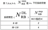
 The values are determined according to the downstream system bandwidth shown in table 7.1.6.3-1 in fig. 1.
For PDCCH DCI Format 1A, 1B or 1D, or for EPDCCH DCI Format 1A, 1B or 1D, or for MPDCCH DCI Format 6-1A, the resource allocation type 2 field is composed of a starting Resource Block (RB)start) And allocating resource blocks L according to virtual continuanceCRBsIs determined by the length of (a) is determined by the length of (b). If it is not The resource indicates the value of
 Defining, if not, the data of the user,
 wherein L isCRBs>1And should not exceed
For PDCCH DCI format 1C, the resource block allocation type 2 field consists of a starting resource block And allocating resource blocks according to virtual continuance
 Is determined by the length of (a) is determined by the length of (b). If it is not
 The resource indicates the value of
 Defining, if not, the data of the user,
 wherein,
 and is
 Here, L'CRBs≥1And should not exceed
UL resource allocation
8.1.1 uplink resource allocation type 0
Resource allocation information for uplink resource allocation type 0 indicates to scheduled UEs that there is nVRBA set of virtual resource block indices of the represented consecutive allocations. The resource allocation field in the scheduling grant consists of starting Resource Blocks (RBs)START) And resource blocks (L) according to the consecutive allocationCRBs≥1) Is determined by the length of (a) is determined by the length of (b). For BL/CE UEs, uplink resource allocation type 0 is only applicable for UEs configured with cemoda, and in this subclause, if it is not
 The resource indicates the value of
 Defining, if not, the data of the user,
8.1.3 uplink resource allocation type 2
The uplink resource allocation type 2 is applicable only to BL/CE UEs configured with cemobe. The resource allocation information for uplink resource allocation type 2 indicates to the scheduled UE the set of consecutive allocated resource blocks within the narrow band given in table 8.1.3-1 of fig. 2.
[TS36.212 v13.2.0]
DCI format for BL/CE UE
5.3.3.1.10 Format 6-0A
DCI format 6-0A is used to schedule PUSCH in one UL cell.
The following information is transmitted through DCI format 6-0A:
flag-1 bit to distinguish Format 6-0A/Format 6-1A, where a value of 0 indicates Format 6-0A and a value of 1 indicates Format 6-1A
A hop flag-1 bit, where a value of 0 indicates that hopping is not enabled and a value of 1 indicates that hopping is enabled, as defined in section [2] section 5.3.4,
resource block allocation for PUSCH Bits, e.g. [3]]As defined in (1):
- the bits providing the narrowband index, e.g. at [2]]As defined in section 5.2.4
-5 bits provide resource allocation within a specified narrow band using UL resource allocation type 0
Modulation and coding scheme-4 bits, as defined in section [3] 8.6
Retransmission times 2 bits, as defined in section [3] 8.0
Number of HARQ processes-3 bits
New data indicator-1 bit
Redundancy version-2 bits
TPC Command-2 bits for scheduled PUSCH, as defined in [3] section 5.1.1.1
UL index-2 bits, as defined in [3] sections 5.1.1.1, 7.2.1, 8 and 8.4 (this field exists only for TDD operation with uplink configuration-downlink configuration 0)
Downlink Assignment Index (DAI) -2 bits, as defined in [3] section 7.3 (this field exists only for TDD primary cell and TDD operation or FDD operation with uplink configuration-downlink configuration 1-6). This field is reserved when the maximum number of retransmissions configured for PDSCH or MPDCCH is greater than 1. )
CSI request-1 bit, as defined in section [3] 7.2.1
SRS request-1 bit. An explanation of this field is provided in section 8.2 of [3 ].
DCI subframe retransmission times-2 bits, as defined in section [3] 9.1.5
If the number of information bits in format 6-0A mapped to a given search space is less than the payload size of format 6-1A (including any padding bits added to format 6-1A) used to schedule the same serving cell and mapped to the same search space, a zero format should be added to format 6-0A until the payload size equals the size of format 6-1A.
5.3.3.1.11 Format 6-0B
DCI format 6-0B is used to schedule PUSCH in one UL cell.
The following information is transmitted through DCI format 6-0B:
flag-1 bit for distinguishing format 6-0B/format 6-1B, where a value of 0 indicates format 6-0B and a value of 1 indicates format 6-1B
Resource block allocation for PUSCH Bits, e.g. [3]]As defined in (1):
- the bits providing a narrow-band index, e.g. [2]]As defined in section 5.2.4
-3 bits provide resource allocation within a specified narrow band, as specified in section [3] 8.1.3
Modulation and coding scheme-4 bits, as defined in section [3] 8.6
Retransmission times-3 bits, as defined in section [3] 8.0
Number of HARQ processes-1 bit
New data indicator-1 bit
DCI subframe retransmission times-2 bits, as defined in section [3] 9.1.5
If the number of information bits in format 6-0B mapped to a given search space is less than the payload size of format 6-1B (including any padding bits added to format 6-1B) used to schedule the same serving cell and mapped to the same search space, then zeros should be added to format 6-0B until the payload size equals the size of format 6-1B.
5.3.3.1.12 Format 6-1A
DCI format 6-1A is used for compact scheduling of one PDSCH codeword and a random access procedure initiated by a PDCCH order in one cell. DCI corresponding to the PDCCH order may be carried by the MPDCCH.
The following information is transmitted through DCI format 6-1A:
-flag-1 bit for distinguishing format 6-0A/format 6-1A, where a value of 0 indicates format 6-0A and a value of 1 indicates format 6-1A
Format 6-1A is only used for the random access procedure initiated by the PDCCH order when format 6-1A CRC is scrambled with a C-RNTI pair, and all remaining fields are set as follows:
-resource block allocation Bits, where all bits shall be set to 1
Preamble index-6 bits
-PRACH mask index-4 bits, [5]
-initiation CE level-2 bits provide PRACH initiation CE level, as defined in [5]
-setting all remaining bits in format 6-1A for compact scheduling of allocation of one PDSCH codeword to zero
-in addition to that,
a hop flag-1 bit, where a value of 0 indicates that hopping is not enabled and a value of 1 indicates that hopping is enabled, as defined in section [2] section 6.4.1,
-resource block allocation-for PDSCH Bits, e.g. [3]]Defined as follows:
- the bits providing a narrow-band index, e.g. [2]]As defined in section 6.2.7,
-5 bits provide resource allocation using DL resource allocation type 2 within a specified narrow band
Modulation coding scheme-4 bits, as defined in section [3] 7.1.7
Retransmission times-2 bits, as defined in section [3] 7.1.11
Number of HARQ processes-3 bits (for FDD primary cell case), 4 bits (for TDD primary cell case)
New data indicator-1 bit
Redundancy version-2 bits
TPC Command-2 bits for PUCCH, as defined in section [3] 5.1.2.1
-if format 6-1A CRC is scrambled by RA-RNTI:
-reserving the most significant bits of the TPC command.
-the least significant bit indication of the TPC command is indicated by [3]]Column of the defined TBS Table
-if the least significant bit is 0, then If not, then,
else
-two bits containing the most significant bits representing the TPC command
Downlink allocation index-the number of bits as specified in table 5.3.3.1.2-2. For PDSCH or MPDCCH, this field is reserved when the configured maximum number of retransmissions is greater than 1.
Antenna port and scrambling identity-2 bits representing values 0 to 3 as specified in table 5.3.3.1.5C-1. This field will only occur when PDSCH transmission is configured through TM 9.
SRS request-1 bit. The interpretation of this field is provided in section [3] 8.2
TPMI information for precoding-the number of bits as specified in table 5.3.3.1.3A-1.
TPMI information indicates which codebook index is used in table 6.3.4.2.3-1 in [2] or table 6.3.4.2.3-2 corresponding to single layer transmission. This field will only occur when PDSCH transmission is configured through TM 6.
PMI acknowledgement for precoding-1 bit as specified in table 5.3.3.1.3A-2. This field will only occur when PDSCH transmission is configured through TM 6.
HARQ-ACK resource offset-2 bits, as defined in section [3] 10.1
DCI subframe retransmission times-2 bits, as defined in section [3] 9.1.5
When format 6-1A CRC is scrambled by RA-RNTI, then the following fields among the above fields are reserved:
number of HARQ processes
-new data indicator
-downlink allocation index
-HARQ-ACK resource offset
If the UE is not configured to decode MPDCCH with CRC scrambled by C-RNTI and the number of information bits in Format 6-1A is less than the number of information bits in Format 6-0A, then zeros should be added to Format 6-1A until the payload size equals the size of Format 6-0A.
If the UE is configured to decode MPDCCH with a CRC scrambled by a C-RNTI and the number of information bits in format 6-1A mapped to a given search space is less than the number of information bits in format 6-0A used to schedule the same serving cell and mapped to the same search space, zeros should be added to format 6-1A until the payload size equals the size of format 6-0A.
5.3.3.1.13 Format 6-1B
DCI format 6-1B is used to schedule one PDSCH codeword in one cell.
The following information is transmitted through DCI format 6-1B:
flag-1 bit to distinguish Format 6-0B/Format 6-1B, where a value of 0 indicates Format 6-0B and a value of 1 indicates Format 6-1B
Format 6-1B is only used for the random access procedure initiated by the PDCCH order when the format 6-1B CRC is scrambled with the C-RNTI, and all remaining fields are set as follows:
-reserved bits Bits, where all bits should be set to 1
Preamble index-6 bits
-PRACH mask index-4 bits [5]
-initiation CE level-2 bits, providing PRACH initiation CE level, as defined in [5]
-setting all remaining bits of the allocation for compact scheduling of one PDSCH codeword in format 6-1B to zero
In addition to this, the present invention is,
modulation and coding scheme-4 bits, as defined in section [3] 7.1.7
-resource block allocation-for PDSCH Bits, e.g. [3]]As defined in (1):
- the bits providing a narrow-band index, e.g. [2]]As defined in section 6.2.7
The-1 bit provides resource allocation within a specified narrow band, where a value of 0 represents an RB with PRB index {0,1,2,3} and a value of 1 represents the use of all 6 PRBs.
Retransmission times-3 bits, as defined in section [3] 7.1.11
Number of HARQ processes-1 bit
New data indicator-1 bit
HARQ-ACK resource offset-2 bits, as defined in section [3] 10.1
DCI subframe retransmission times-2 bits, as defined in section [3] 9.1.5
When format 6-1B CRC is scrambled using RA-RNTI, the following fields in the above fields are reserved:
number of HARQ processes
-new data indicator
-HARQ-ACK resource offset
If the UE is not configured to decode MPDCCH with CRC scrambled by C-RNTI and the number of information bits in Format 6-1B is less than the number of information bits in Format 6-0B, then zeros should be added to Format 6-1B until the payload size equals the size of Format 6-0B.
If the UE is configured to decode MPDCCH with a CRC scrambled by a C-RNTI and the number of information bits in format 6-1B mapped to a given search space is less than the number of information bits for format 6-0B used to schedule the same serving cell and mapped to the same search space, zeros should be added to format 6-1B until the payload size equals the size of format 6-0B.
5.3.3.1.14 Format 6-2
DCI format 6-2 is used for paging and direct indication.
The following information is transmitted through DCI format 6-2:
flag to distinguish paging/direct indication-1 bit, value 0 for direct indication, value 1 for paging
-if the flag is 0:
direct indication information-8 bits, providing direct indication of system information updates and other fields, as defined in [6]
-adding reserved information bits until the size equals the size of format 6-2 with flag ═ 1
-if the flag is 1:
resource block allocation for narrowband indexing Bits, e.g. [3]]Section 7.1.6
Modulation and coding scheme-3 bits, as defined in section [3] 7.1.7
Retransmission times-3 bits, as defined in section [3] 7.1.11
DCI subframe retransmission times-2 bits, as defined in section [3] 9.1.5
[ MPDCCH search space configuration ]
As an MPDCCH search space for version-13 BL/CE terminals, four search spaces are defined. The four search spaces include a common search space of type 0, which is defined to listen only when the mode is set to cemoda; a type1 common search space for paging; common search space for random access procedure type 2; and a UE-specific search space for terminal-specific data transmission and reception.
The specific MPDCCH search space configuration is extracted from the TS36.213 document to be attached.
[TS36.213]
9.1.5 MPDCCH allocation procedure
The BL/CE UE will listen on the set of candidate MPDCCH on one or more narrow bands (described in subclause 5.2.4 of [3 ]) (which is configured by higher layer signaling for control information), where listening means attempting to decode each MPDCCH in the set according to all the monitored DCI formats. The narrowband in the subframe for MPDCCH listening is determined as described in [3 ].
UEs other than BL/CE UEs do not need to listen to the MPDCCH.
Higher layer signaling may configure the BL/CE UE with one or two MPDCCH-PRB sets for MPDCCH listening. The PRB pairs corresponding to the MPDCCH-PRB set are indicated by the higher layers. Each MPDCCH-PRB set is composed of 0 to N'ECCE,p,k-1Numbered ECCE set of N'ECCE,p,kIs the number of ECCEs in MPDCCH-PRB set p for subframe k.
The MPDCCH-PRB set may be configured by higher layers for localized MPDCCH transmission or distributed MPDCCH transmission.
A set of candidate MPDCCH to listen to is defined according to the MPDCCH search space.
The BL/CE UE will listen to one or more of the following search spaces:
-a type 0-MPDCCH common search space if configured in CEModeA,
-type 1-MPDCCH common search space,
-type 2-MPDCCH common search space, and
-MPDCCH UE-specific search space.
A BL/CE UE configured with CEModeB does not need to listen to the type 0-MPDCCH common search space.
The BL/CE UE does not need to listen to both the MPDCCH UE-specific search space and the type 1-MPDCCH common search space.
The BL/CE UE does not need to listen to both the MPDCCH UE-specific search space and the type 2-MPDCCH common search space.
A BL/CE UE is not expected to listen to the candidate MPDCCH if the ECCE corresponding to the candidate MPDCCH is mapped to a PRB pair that overlaps with the transmission of the PDSCH previously scheduled in the same subframe. For aggregation level L '24 or L' 12 ECCEs, the number of ECCEs refers to the MPDCCH mapped to REs of the 2+4PRB set, e.g., [3 ═ 4PRB set]As defined in (1). MPDCCH search space at aggregation level L' ∈ {1, 2, 4, 8, 16, 12, 24} and retransmission level R ∈ {1, 2, 4, 8, 16, 32, 64, 128, 256} Defined by the set of candidate MPDCCH, where each candidate is retransmitted in the set of R consecutive BL/CE downlink subframes starting at subframe k. For MPDCCH-PRB set p, and search space
 ECCE of corresponding candidate MPDCCH m
 Given that, the content of the compound (A),
wherein,
i=0,...,L′-1


Y for MPDCCH specific search spacep,kDetermined as described in sub-clause 9.1.4, and Y is the same for type 0-MPDCCH common search space, type 1-MPDCCH common search space, and type 2-MPDCCH common search spacep,k=0。
It is not desirable for the BL/CE UE to listen to the MPDCCH in subframes other than the BL/CE DL subframe.
Prior to the BL/CE UE receiving the higher layer configuration of the MPDCCH UE-specific search space, the BL/CE UE listens to the MPDCCH according to the same MPDCCH search space and narrowband configuration as used for MPDCCH scheduling Msg 4.
The aggregation level and retransmission level defining the MPDCCH search space and the number of MPDCCH candidates listened to are given as follows:
UE-specific search space for MPDCCH
-if the BL/CE UE is configured with Or
Or PRB pair, and mPDCCH-NumRepetition ═ 1, and
-if the MPDCCH-PRB set is configured for distributed transmission, the aggregation level defining the search space and the number of candidate MPDCCH monitored are listed in tables 9.1.4-1a and 9.1.4-1b, for which L ≦ 24, L is replaced by L', and is replaced by
-if the MPDCCH-PRB set is configured for localized transmission, the aggregation level defining the search space and the number of candidate MPDCCH listened to are listed in tables 9.1.4-2a and 9.1.4-2b, where L' is substituted, and is replaced by
Else
-if the UE is configured with CEModeA, and or
or The aggregation level and retransmission level defining the search space and the number of candidate MPDCCH's being listened to are listed in table 9.1.5-1a of fig. 3
-if the UE is configured with CEModeA, and the aggregation level and retransmission level defining the search space and the number of candidate MPDCCH's being listened to are listed in table 9.1.5-1b of fig. 4
-if the UE is configured with cemobe, and or
or The aggregation level and retransmission level defining the search space and the number of MPDCCH candidates listened to are listed in table 9.1.5-2a of fig. 5.
-if the UE is configured with CEModeB, and the aggregation level and retransmission level defining the search space and the number of candidate MPDCCH's being listened to are listed in table 9.1.5-2b of fig. 6


r1, r2, r3, r4 are represented by Table 9.1.5-3 of FIG. 7 by replacing r with the value of the upper layer parameter mPDCCH-NumRepetitionmaxThe value is determined.
PRB pairs within the narrowband corresponding to the MPDCCH-PRB set are indicated by the higher layers and are determined using the description given in subclause 9.1.4.4.
If the higher layer configuration number PRB-Pairs-r13 for the MPDCCH-PRB set p is 6, then And the number of PRB pairs in the MPDCCH-PRB set p is 2+ 4.
If it is a type 2-MPDCCH common search space, then
-the PRB pairs of the 2PRB set in the 2+4PRB set correspond to the PRB pairs with the largest two PRB indices in the MPDCCH-PRB set p.
-PRB pairs of the 4PRB set in the 2+4PRB set correspond to PRB pairs with the smallest 4PRB indices in the MPDCCH-PRB set p.
-PRB pairs of the 2+4PRB set in the 2+4PRB set correspond to all PRB pairs in the MPDCCH-PRB set p
For type 0-MPDCCH common search spaces, the narrowband position and MPDCCH-PRB set p are the same as the MPDCCH UE-specific search space, and
if is Then
Then
-to L'-8, And, retransmission levels r1, r2, r3, r4 are given in table 9.1.5-3 in fig. 7. For all the other cases it is also possible to,
if is Then
Then
For L' 16, the reaction mixture is, and the retransmission grades r1, r2, r3, r4 are given in table 9.1.5-3 in fig. 7. For all the other cases it is also possible to,
if is Then
Then
For L' 24, the first step of the method, and the retransmission classes are given in table 9.1.5-3 in fig. 7. For all the other cases it is also possible to,
for type 1-MPDCCH common search space, the number of PRB pairs in MPDCCH-PRB set p is 2+4PRB pairs, and
for L' -24, the reaction is carried out, and wherein the retransmission levels r1, r2, r3, r4 are represented by tables 9.1.5-4 in FIG. 8 by replacing r with the higher layer parameter mPDCCH-NumRepetition-PagingmaxIs determined.
-for all the other cases,
for type 2-MPDCCH common search space, the number of PRB pairs in MPDCCH-PRB set p is 2+4PRB pairs, and
-if the latest coverage enhancement levels for PRACH are coverage enhancement levels 0 and 1, the aggregation level and retransmission level defining the search space and the number of MPDCCH candidates listened to are determined from table 9.1.5-1b in fig. 4, assuming that the number of candidates is zero for L' < 8.
-if the latest coverage enhancement levels for PRACH are coverage enhancement levels 2 and 3, the aggregation level and retransmission level defining the search space and the number of MPDCCH candidates listened to are determined according to 9.1.5-2b in fig. 6.
Wherein r1, r2, r3, r4 are determined by replacing r with the value of the upper layer parameter mPDCCH-NumRepetition-RA according to Table 9.1.5-3 in FIG. 7maxIs determined.
In table 9.1.5-1a in fig. 3, table 9.1.5-1b in fig. 4, table 9.1.5-2a in fig. 5, table 9.1.5-2b in fig. 6, L' applies to type 0MPDCCH common search space, type 1MPDCCH common search space, type 2MPDCCH common search space And L' is suitable for
 Wherein L ═ L'/2 substitutionThe value of L'.
For type 1-MPDCCH common search spaces and type 2-MPDCCH common search spaces, distributed MPDCCH transmission is used.
For MPDCCH UE-specific search space, type 0 common search space, and type 2 common search space, the position of starting subframe k is defined by k ═ kbGiven, wherein kbIs the b-th consecutive BL/CE DL subframe from subframe k0, b-u · rj, and j e {1, 2,3, 4}, where,
sub-frame k0 is the condition is satisfied Wherein T ═ rmax·G
-for an MPDCCH UE-specific search space, a type 0 common search space, G is given by a higher layer parameter MPDCCH-startSF-UESS,
for type 2 common search spaces, G is given by the higher layer parameter mPDCCH-startSF-CSS-RA-r13
-rmaxGiven by the higher layer parameter mPDCCH-NumRepetition, and
r1, r2, r3, r4 are given in table 9.1.5-3 of fig. 7.
It is not desirable for a BL/CE UE to be configured to result in r being a non-integer value of TmaxAnd the value of G.
For a type1 common search space, k0 and is determined by the location of the paging opportunity sub-frame,
if the systemlnformationblocktype 1-BR or SI message is sent in one narrowband in subframe k, the BL/CE UE will assume that the MPDCCH in the same narrowband in the subframe is discarded.
If any ECCE corresponding to any candidate MPDCCH thereof appears at nfIn frames before 0 and also in nfWithin frame 0, the BL/CE UE does not need to listen to the MPDCCH search space.
For an MPDCCH UE-specific search space or for a type 0 common search space, if a high-layer parameter MPDCCH-NumRepetition is set to 1; or for the type 2 public search space, if the high-level parameter mPDCCH-NumRepetition-RA is set to 1; then
BL/CE UEs need not listen to the MPDCCH
For TDD and normal downlink CP, in special subframes for special subframe configurations 0 and 5 as shown in Table 4.2-1 of [3],
-in special subframes for special subframe configurations 0, 4 and 7 shown in table 4.2-1 of [3], for TDD and extended downlink CP;
if not, then,
BL/CE UEs need not listen to the MPDCCH
For TDD, in special subframes if BL/CE UE is configured with cemobe
For TDD and normal downlink CP, if BL/CE UE is configured with CEModeA, in special subframes for special subframe configurations 0,1,2, 5, 6, 7 and 9 as shown in Table 4.2-1 of [3]
For TDD and extended downlink CP, if BL/CE UE is configured with CEModeA, in special subframes for special subframe configurations 0, 4, 7, 8 and 9 shown in table 4.2-1 of [3 ].
The number of MPDCCH retransmissions is indicated in the "DCI subframe retransmission times" field of the DCI according to the mapping in table 9.1.5-5 in fig. 9.
[ further enhancement of MTC ]
As described above, the additional enhanced features for BL/CE terminals defined in 3GPP release-13 will be discussed in the 3GPP rel-14 system, and a specific range is extracted from the following WID document RP-161321 to be attached.
[RP-161321]
Reason for 3
Providing IoT over a cellular network has proven to be an important opportunity for mobile operators. In release 13, two types of low-cost IoT devices with enhanced coverage and long battery life are specified: eMTC devices and NB-IoT devices with UE bandwidths of 6PRB and 1PRB (1PRB 180kHz physical resource block), respectively.
Important in many IoT applications is UE location and tracking, such as asset tracking. But GNSS based positioning methods are not suitable for many IoT applications. Furthermore, when using the 3GPP positioning functions defined for normal UEs, the narrow UE bandwidth poses a challenge to the positioning accuracy. In release-13, only limited positioning functionality is provided for these UEs. Therefore, fulfilling the core requirements according to release-13 and considering the improved 3GPP positioning method is essential for improving the 3GPP based IoT ecosystem
When many devices in the same cell need to receive the same information at the same time, for example in the case of a firmware or software roll-out upgrade, it is more efficient to use multicast transmission instead of unicast transmission in many cases. The low complexity multicast function may be introduced in the form of a conventional MBSFN transmission function or a narrowband format as a small extension of the recently introduced single cell point-to-multipoint transmission (SC-PtM) function.
In release-13, the requirements for reduced complexity, extended battery life, and enhanced coverage of devices such as sensors, meters, smart readers, and the like are addressed. Other types of devices/use cases, such as wearable devices with voice capabilities and health monitoring devices, share some of these requirements. However, a subset of these devices are not fully covered by the release-13 improvement scope, as they require higher data rates above 1Mbps, mobility, and they can support more delay sensitive services. It is important to address these use cases with higher data rate requirements and mobility than those addressed by release-13 eMTC, while maximizing the features of reduced power consumption and complexity and enhanced link budget that can be achieved using existing release-13 eMTC solutions.
4 purpose
4.1 purpose of SI or core part WI or test part WI
The objective is to specify the following improvements for machine type communication for BL/ce (emtc) UEs.
Positioning [ RAN4, RAN1]
E-CID: RSRP/RSRQ measurement
E-CID: UE Rx-Tx time difference measurement
OTDOA: core requirements
From RAN # 73: the accuracy, UE complexity and power consumption for OTDOA can be studied (considering NB-IoT results)
Multicast [ RAN2 Pin, RAN1]
Extended version-13 SC-PTM to support multicast downstream transmission (e.g. firmware or software update, group messaging)
Introducing necessary enhancement functions to support narrowband operation, e.g. supporting MPDCCH and coverage enhancement (e.g. retransmission)
Mobility enhancements [ RAN4 only ]
Full standard supporting eMTC inter-frequency measurement [ RAN4]
Higher data rates [ RAN1, RAN2, RAN4]
Assigning HARQ-ACK bundling in CE mode A in HD-FDD
Maximum TBS of greater size
Larger maximum PDSCH/PUSCH channel bandwidth in connected mode at least in CE mode A to enhance support for e.g. voice and audio streams or other applications and scenarios
Up to 10 DL HARQ processes in CE mode a in FD-FDD
The present disclosure proposes a PDSCH/PUSCH resource allocation method for a new rel-14MTC terminal (for convenience of description of the present disclosure, it is referred to as a hentc terminal, but the present disclosure is not limited to this term) that supports an extended PDSCH/PUSCH channel bandwidth compared to a release-13 BL/CE terminal, and a DCI configuration method according to the method.
As described above, the hemcc terminal requiring data rate enhancement is extended beyond the narrowband PDSCH and PUSCH transmission/reception bandwidths defined as 6 PRBs based on the maximum transmission/reception bandwidth support of the existing release-13 BL/CE terminal, as compared to the existing release-13 BL/CE terminal. Therefore, it is difficult to reuse the DCI format and the resource allocation method for the release-13 BL/CE terminal.
Accordingly, the present disclosure proposes a PDSCH/PUSCH resource allocation method for a hemcc terminal.
When a DCI format transmitting PDSCH or PUSCH resource allocation information for an arbitrary hemcc terminal is configured as a method for allocating PDSCH/PUSCH resources for an arbitrary hemcc, it is defined as an information region including information indicating a plurality of narrow bands.
Specifically, a plurality of narrowband allocation information may be configured by starting narrowband index indication information, the number of narrowband consecutively allocated from the starting narrowband index, and information indicating a value of K. In this case, the start narrowband index indication information and the allocated number of narrowbands and the information indicating the value of K are defined as separate information areas to be independently set and transmitted. Alternatively, when a narrowband indication value is set through one information region, the starting narrowband index, the number of consecutively allocated narrowbands, and the value K may be defined as being deducted by a function based on the narrowband indication value.
Alternatively, the K value may have any fixed value as a function of the capability or system bandwidth of the HeMTC terminal, or may be semi-statically set through UE-specific/cell-specific RRC signaling. Further, by transmitting DCI of PDSCH/PUSCH resource allocation information, the K value may be defined to include only indication information of the starting narrowband index.
As another method for allocating a plurality of narrow bands, N consecutive non-overlapping narrow bands of a narrow band group configured for an arbitrary system bandwidth are grouped to define a narrow band group, and when a DCI format transmitting resource allocation information for a PDSCH and a PUSCH is configured, information indicating the narrow band group is included. Such a narrowband group is also referred to as a wideband, and the narrowband group indication information may be wideband indication information.
Specifically, in the range from #0 to # (
(narrowband groups # 0 to # in case of UL) ) Configuring narrowband group (which is composed of N continuous narrow bands to configure arbitrary system bandwidth from #0 to # #)
 Is/are as follows
 A narrow band (alternatively, #0 to # of UL)
 Is/are as follows
 Narrowband number increasing order configuration) may be defined as including narrowband group index indication information allocated by transmitting a DCI format of PDSCH or PUSCH resource allocation information.
In this case, the N value, which is the number of narrowbands configuring one narrowband group, is determined by a function of the system bandwidth and the capability of the hemcc terminal, or is semi-statically set through cell-specific/UE-specific RRC, or is dynamically set through DCI format transmitting PDSCH/PUSCH resource allocation information.
In addition, the DCI format transmitting PDSCH or PUSCH resource allocation information of the hemcc terminal may further include PRB (or VRB) allocation information in a plurality of narrowband and the plurality of narrowband allocation indication information.
The entire system band may be defined as a type 2 narrowband (or enhanced narrowband) of a new size (e.g., M PRBs, in this case, M is any natural number satisfying M > 6) based on a transmission/reception bandwidth of PDSCH/PUSCH of the hemcc terminal, based on which resources are allocated for PDSCH/PUSCH of the hemcc terminal.
That is, when a DCI format transmitting PDSCH/PUSCH resource allocation information of an arbitrary HEMTC terminal is configured, it may be defined to include type 2 narrowband (or enhanced narrowband) allocation information. In this case, the number of consecutive PRBs configuring one type 2 narrowband, i.e., the M value, may be determined based on the PDSCH/PUSCH transmission/reception bandwidth and the system bandwidth of the HeMTC, or may be set through cell-specific/UE-specific RRC signaling.
In addition, the DCI format transmitting PDSCH or PUSCH resource allocation information of the HeMTC terminal may further include PRB (or VRB) allocation information in a type 2 narrowband (or enhanced narrowband) and the above-described type 2 narrowband (or enhanced narrowband) allocation indication information.
It is defined that DCI formats defined for a general LTE terminal (e.g., DCI 1A for PUSCH and DCI format 0 for PUSCH) are reused as DCI formats for transmitting resource allocation information of PDSCH/PUSCH for hemcc. When monitoring DCI through the search space based on the MPDCCH, it can be determined that the HeMTC terminal performs blind decoding based on the DCI format for the legacy LTE terminal without performing blind decoding based on the existing DCI formats (i.e., DCI formats 6-0A, 6-0B, 6-1A, and 6-1B) defined for the MPDCCH.
As described in point 1, in the case of a hemcc terminal, in order to allocate PDSCH/PUSCH resources, a new resource allocation method according to a method different from the resource allocation method defined for a release-13 BL/CE UE and a DCI format 6 series according to the method need to be defined. However, depending on the set CE mode and the type of message expected to be received (e.g., unicast traffic, RAR, or paging), the hemcc terminal also needs a method of listening to resource allocation based on the narrowband defined for the release-13 BL/CE UE and the DCI format 6-1A, 6-1B or 6-0A, 6-0B or 6-2 according to this method.
As an example thereof, in case of the type 0 common search space, the type1 common search space, the type 2 common search space, the HeMTC terminal follows the DCI format defined for the release-13 BL/CE UE and a method of allocating PDSCH/PUSCH resources according to the DCI format. In addition, only the USS needs to be defined to follow a DCI format newly defined for the hemcc terminal and a method of allocating resources according to the DCI format.
Further, only when the USS is set to cemoda, the USS follows a DCI format newly defined for the hemcs terminal and a method of allocating resources according to the DCI format. When the USS is set to cemobe, the UCC follows a method for listening to the existing DCI formats 6-1B and 6-0B and allocating resources according to the DCI formats.
Alternatively, an information region indicating whether to indicate an existing narrowband-based resource allocation method defined in release-13 and whether to indicate a new extended bandwidth-based resource allocation method is included in the newly defined DCI format, thereby being defined to enable the terminal to set whether to apply the release-13 resource allocation method or the new extended bandwidth-based resource allocation method.
Fig. 10 illustrates a procedure of a method for allocating data channel resources in a wireless communication system according to the present exemplary embodiment.
Referring to fig. 10, according to the present exemplary embodiment, a narrowband defined as six consecutive PRBs configuring the entire system bandwidth is configured in a wireless communication system (S1000).
Further, configuring is defined as configuring a wideband of N non-overlapping narrow bands of the system bandwidth.
Here, the number N of narrow bands configuring one wide band may be determined based on the number of narrow bands configuring the entire system bandwidth.
For example, when the number of narrow bands configuring the entire system bandwidth is equal to or greater than 4, four non-overlapping narrow bands configure one wide band. That is, when the number of narrow bands configuring the entire system bandwidth is equal to or greater than 4, N is set to 4.
As another example, when the number of the narrow bands configuring the entire system bandwidth is less than 4, all the narrow bands configuring the system bandwidth may configure one bandwidth. That is, the number of broadband configuring the entire system is set to 1.
The narrow bands configuring one wide band may be configured in order of increasing number of narrow bands.
Among the narrow bands configuring the system bandwidth, one or more narrow bands are allocated as resources for transmission/reception of the data channel (S1010).
Information indicating the allocated narrowband is transmitted through Downlink Control Information (DCI) (S1020).
Here, the Downlink Control Information (DCI) may include information indicating a narrowband index starting from an allocated narrowband for transmission/reception of the data channel.
When N non-overlapping narrow bands configure one wideband, the downlink control information DCI may include information indicating a wideband index.
The allocated resources for transmitting/receiving the data channel are identified by information on the allocated narrowband and information indicating a starting narrowband index or a wideband index included in Downlink Control Information (DCI), and the data channel can be transmitted/received through the resources.
Fig. 11 illustrates a process for listening to data channel assignments in a wireless communication system according to the present exemplary embodiment.
Referring to fig. 11, in a wireless communication system, a terminal receives downlink control information indicating allocation of data channel resources from a base station (S1100).
Downlink Control Information (DCI) may include information indicating a starting narrowband index of one or more narrowbands allocated for transmission/reception of a data channel.
Alternatively, when N non-overlapping narrow bands configure one wideband, information indicating the wideband index may be included.
Here, the number N of narrow bands configuring one wide band may be determined based on the number of narrow bands configuring the entire system bandwidth, and one wide band may be configured in an order in which indexes of the narrow bands configuring the system bandwidth increase.
The terminal identifies information on one or more allocated narrowbands for transmitting/receiving a data channel through downlink control information DCI and a starting narrowband index or wideband index (S1110).
The terminal transmits/receives a data channel based on narrowband allocation information identified through Downlink Control Information (DCI).
By doing so, the BL/CE UE defined in 3GPP release-13 can transmit/receive a data channel using the extended data channel resources.
Fig. 12 illustrates a configuration of a base station 1200 according to the present exemplary embodiment.
Referring to fig. 12, a base station 1200 according to the present exemplary embodiment includes a control unit 1210, a transmitting unit 1220, and a receiving unit 1230.
The control unit 1210 controls the overall operation of the base station 1200 required by the present disclosure described above to be performed according to the resource allocation, the corresponding DCI format for the hemcc, and the DCI listening method of the hemcc terminal.
The transmitting unit 1220 and the receiving unit 1230 are used to transmit and receive signals, messages, and data required to implement the present disclosure to and from the terminal.
Fig. 13 illustrates a configuration of a user terminal 1300 according to the present exemplary embodiment.
Referring to fig. 13, a user terminal 1300 according to the present exemplary embodiment includes a receiving unit 1310, a control unit 1320, and a transmitting unit 1330.
The receiving unit 1310 receives downlink control information, data, and messages from a base station through corresponding channels.
The control unit 1320 controls the overall operation of the user terminal 1300 required by the present disclosure described above to be performed according to the resource allocation, the corresponding DCI format for the hemcc, and the DCI listening method of the hemcc terminal.
The transmitting unit 1330 transmits uplink control information, data, and messages to the base station through corresponding channels.
In order to simplify the description of the specification, the standard contents and standard files mentioned in the above exemplary embodiments are omitted, but constitute a part of the specification. Therefore, it should be understood that when standard contents and partial contents of standard files are added to the specification or described in the claims, they are also covered by the scope of the present disclosure.
It should be understood that although exemplary embodiments of the present disclosure have been described herein for illustrative purposes, various modifications, changes, and substitutions may be made by those skilled in the art without departing from the scope and spirit of the present disclosure. Accordingly, the exemplary embodiments of the present disclosure are for illustrative purposes only, and are not intended to limit the technical spirit of the present disclosure. The scope of the technical spirit of the present disclosure is not limited thereto. The scope of the present disclosure should be construed based on the appended claims, and all technical concepts within the equivalent scope thereof should be construed as falling within the scope of the present disclosure.
Claims (16)
1. A method for allocating data channel resources in a wireless communication system, the method comprising:
configuring at least one narrowband using physical resource blocks configuring a system bandwidth, each of the at least one narrowband comprising six consecutive physical resource blocks;
allocating one or more narrow bands among the at least one narrow band configured to transmit/receive a data channel; and
information indicating the allocated one or more narrow bands is transmitted through the downlink control information,
wherein the downlink control information includes information indicating an index of a wideband configured by N non-overlapping ones of the narrow bands configuring the system bandwidth, where N is an integer greater than 0.
2. The method of claim 1, wherein the downlink control information comprises information indicating an index of a starting narrowband of the one or more allocated narrowbands.
3. The method of claim 1, wherein the wideband is configured by four non-overlapping narrowbands when the number of narrowbands configuring the system bandwidth is equal to or greater than 4.
4. The method of claim 1, wherein the wideband configuring the system bandwidth is configured in an order of increasing narrowband number.
5. A method for listening for data channel resource allocations in a wireless communication system, the method comprising:
receiving downlink control information from a base station;
identifying one or more narrow bands allocated for transmission/reception of a data channel through the downlink control information; and
transmitting/receiving the data channel through the one or more allocated narrowbands,
wherein the downlink control information includes information on one or more narrow bands allocated for transmission/reception of a data channel among at least one narrow band configured using physical resource blocks of a system bandwidth, wherein each of the at least one narrow band includes six consecutive physical resource blocks, and
wherein the downlink control information includes information indicating an index of a wideband configured by N non-overlapping ones of the narrowbands configuring the system bandwidth.
6. The method of claim 5, wherein the downlink control information comprises information indicating an index of a starting narrowband of the one or more allocated narrowbands.
7. The method of claim 5, wherein the wideband is configured by four non-overlapping narrowbands when the number of narrowbands configuring the system bandwidth is equal to or greater than 4.
8. The method of claim 5, wherein the wideband configuring the system bandwidth is configured in order of increasing narrowband number.
9. A base station for allocating data channel resources in a wireless communication system, the base station comprising:
a control unit configuring at least one narrow band using physical resource blocks configuring a system bandwidth, allocating one or more narrow bands among the configured at least one narrow band to transmit/receive a data channel, and generating downlink control information including information indicating the allocated one or more narrow bands, wherein each of the at least one narrow band includes six consecutive physical resource blocks configuring the system bandwidth; and
a transmitting unit that transmits the downlink control information to a terminal,
wherein the downlink control information includes information indicating an index of a wideband configured by N non-overlapping ones of the narrow bands configuring the system bandwidth, where N is an integer greater than 0.
10. The base station of claim 9, wherein the downlink control information comprises information indicating an index of a starting narrowband of the one or more allocated narrowbands.
11. The base station of claim 9, wherein when the number of narrowbands configuring the system bandwidth is equal to or greater than 4, the wideband is configured by four non-overlapping narrowbands.
12. The base station of claim 9, wherein the wideband configuring the system bandwidth is configured in an order of increasing narrowband numbers.
13. A terminal for listening to data channel resource allocations in a wireless communication system, the terminal comprising:
a receiving unit that receives downlink control information from a base station; and
a control unit identifying one or more narrow bands allocated for transmission/reception of the data channel through the downlink control information and controlling transmission/reception of the data channel through the one or more allocated narrow bands, an
Wherein the downlink control information includes information on one or more narrow bands allocated for transmission/reception of a data channel among at least one narrow band configured using physical resource blocks of a system bandwidth, wherein each of the at least one narrow band includes six consecutive physical resource blocks, and
wherein the downlink control information includes information indicating an index of a wideband configured by N non-overlapping ones of the narrowbands configuring the system bandwidth.
14. The terminal of claim 13, wherein the downlink control information includes information indicating an index of a starting narrowband of the one or more allocated narrowbands.
15. The terminal of claim 13, wherein when the number of narrowbands configuring the system bandwidth is equal to or greater than 4, the wideband is configured by four non-overlapping narrowbands.
16. The terminal of claim 13, wherein the wideband configuring the system bandwidth is configured in an order of increasing narrowband numbers.
Applications Claiming Priority (4)
| Application Number | Priority Date | Filing Date | Title |
|---|---|---|---|
| KR10-2016-0102627 | 2016-08-11 | ||
| KR20160102627 | 2016-08-11 | ||
| KR10-2017-0065832 | 2017-05-29 | ||
| KR1020170065832A KR102042032B1 (en) | 2016-08-11 | 2017-05-29 | Methods for allocating data channel resources in a wireless communication system and apparatuses |
Publications (2)
| Publication Number | Publication Date |
|---|---|
| CN107734692A CN107734692A (en) | 2018-02-23 |
| CN107734692B true CN107734692B (en) | 2021-10-08 |
Family
ID=61160439
Family Applications (1)
| Application Number | Title | Priority Date | Filing Date |
|---|---|---|---|
| CN201710675075.3A Active CN107734692B (en) | 2016-08-11 | 2017-08-09 | Method and apparatus for allocating data channel resources in a wireless communication system |
Country Status (2)
| Country | Link |
|---|---|
| US (1) | US10517074B2 (en) |
| CN (1) | CN107734692B (en) |
Families Citing this family (25)
| Publication number | Priority date | Publication date | Assignee | Title |
|---|---|---|---|---|
| EP3496493B1 (en) * | 2016-08-12 | 2021-06-30 | Huawei Technologies Co., Ltd. | Control information transmission method, base station and user equipment |
| US10667266B2 (en) * | 2016-08-12 | 2020-05-26 | Nokia Technologies Oy | Resource indication for bandwidth allocation in wireless communication |
| CN107872779B (en) * | 2016-09-27 | 2020-12-01 | 中兴通讯股份有限公司 | Resource allocation method and device |
| WO2018082078A1 (en) * | 2016-11-05 | 2018-05-11 | Apple Inc. | Asymmetric bandwidth support and dynamic bandwidth adjustment |
| CN110169170B (en) * | 2017-01-25 | 2021-10-01 | 华为技术有限公司 | A method, device and device for resource allocation |
| EP3616348B1 (en) * | 2017-04-28 | 2026-03-18 | Motorola Mobility LLC | Feedback message transmission for one or more processes |
| EP4358629A3 (en) * | 2017-06-16 | 2024-05-08 | ZTE Corporation | System and method for allocating resource blocks |
| US11012112B2 (en) * | 2018-02-09 | 2021-05-18 | Qualcomm Incorporated | Techniques for flexible resource allocation |
| EP3764709B1 (en) | 2018-04-04 | 2025-04-02 | Huawei Technologies Co., Ltd. | Information transmission method and device |
| RU2768374C1 (en) | 2018-04-04 | 2022-03-24 | Хуавей Текнолоджиз Ко., Лтд. | Data transmission method, communication device, data medium and software product |
| CN110351853A (en) * | 2018-04-04 | 2019-10-18 | 夏普株式会社 | The method and user equipment executed by user equipment |
| WO2019192001A1 (en) * | 2018-04-04 | 2019-10-10 | 华为技术有限公司 | Information transmission method and device |
| EP3790207B1 (en) | 2018-05-11 | 2023-09-13 | Huawei Technologies Co., Ltd. | Information transmission method, communication device, and network device |
| CN110505694A (en) * | 2018-05-17 | 2019-11-26 | 索尼公司 | Electronic equipment and method, computer readable storage medium for wireless communication |
| JP2020031353A (en) * | 2018-08-23 | 2020-02-27 | シャープ株式会社 | Terminal device, base station device, and communication method |
| US11290999B2 (en) * | 2018-09-06 | 2022-03-29 | Qualcomm Incorporated | Techniques for flexible resource allocation |
| KR20200050812A (en) * | 2018-11-02 | 2020-05-12 | 삼성전자주식회사 | Method and apparatus for transmitting and receiving data and feedback in wirelss communication system |
| US12088516B2 (en) * | 2019-02-15 | 2024-09-10 | Apple Inc. | Resource allocation for multi-TRP URLLC |
| ES2945820T3 (en) * | 2019-03-29 | 2023-07-07 | Ericsson Telefon Ab L M | CSI-based precoding on a subset of search space |
| US11523377B2 (en) | 2020-02-14 | 2022-12-06 | T-Mobile Usa, Inc. | LTE resource allocation controller |
| CN113891463B (en) | 2020-07-02 | 2025-04-15 | 维沃移动通信有限公司 | PUSCH signal mapping method, terminal and network side equipment |
| EP4193732A4 (en) * | 2020-08-05 | 2024-04-10 | Lenovo (Beijing) Limited | Scheduling delay determination for emtc |
| CN112330096B (en) * | 2020-10-10 | 2024-06-14 | 北京中电飞华通信有限公司 | A method, system and related equipment for allocating multi-dimensional power basic resources |
| US12088393B2 (en) * | 2020-10-22 | 2024-09-10 | Qualcomm Incorporated | Beam and narrowband management |
| CN117597951A (en) * | 2022-06-02 | 2024-02-23 | 北京小米移动软件有限公司 | A method and device for processing transport blocks |
Family Cites Families (12)
| Publication number | Priority date | Publication date | Assignee | Title |
|---|---|---|---|---|
| US9118812B2 (en) * | 2003-08-01 | 2015-08-25 | Advertising.Com Llc | Audience server |
| KR101537614B1 (en) * | 2008-08-11 | 2015-07-22 | 엘지전자 주식회사 | Method for signaling control information in a wireless communication system using a plurality of frequency blocks |
| KR101962245B1 (en) * | 2011-09-23 | 2019-03-27 | 삼성전자 주식회사 | Method and apparatus for accessing of narrowband terminal to a wireless communication system supporting both wideband terminal and narrowband terminal |
| JP6298263B2 (en) * | 2013-09-26 | 2018-03-20 | 株式会社Nttドコモ | Wireless base station, user terminal, and wireless communication method |
| US10411838B2 (en) * | 2014-01-23 | 2019-09-10 | Qualcomm Incorporated | Coverage enhancements with carrier aggregation |
| WO2016048027A2 (en) * | 2014-09-23 | 2016-03-31 | 엘지전자 주식회사 | Method and user equipment for receiving downlink signal, and method and base station for transmitting downlink signal |
| US20160270038A1 (en) * | 2015-03-11 | 2016-09-15 | Samsung Electronics Co., Ltd | Transmissions of downlink control channels for low cost ues |
| US9877278B2 (en) * | 2015-04-10 | 2018-01-23 | Futurewei Technologies, Inc. | Monitoring a narrowband control channel for a wideband system to reduce power consumption |
| US10932256B2 (en) * | 2015-06-16 | 2021-02-23 | Qualcomm Incorporated | Long-term evolution compatible very narrow band design |
| KR102262300B1 (en) * | 2015-06-17 | 2021-06-08 | 삼성전자 주식회사 | Method and apparatus for signal transmission using narrow band in wirelss cellular communication system |
| US11570597B2 (en) * | 2016-02-08 | 2023-01-31 | Qualcomm Incorporated | Pilot design for uplink (UL) narrow-band internet of things (NB-IoT) |
| US10736113B2 (en) * | 2016-02-16 | 2020-08-04 | Qualcomm Incorporated | Positioning signal techniques for narrowband devices |
-
2017
- 2017-08-09 CN CN201710675075.3A patent/CN107734692B/en active Active
- 2017-08-09 US US15/672,368 patent/US10517074B2/en active Active
Non-Patent Citations (2)
| Title |
|---|
| 3GPP TSG RAN WG1 Meeting #82 R1-153967;Panasonic;《3GPP TSG RAN WG1 Meeting #82 R1-153967》;20150813;全文 * |
| 3GPP TSG RAN WG1 Meeting #82 R1-154227;LG Electronics;《3GPP TSG RAN WG1 Meeting #82 R1-154227》;20150825;全文 * |
Also Published As
| Publication number | Publication date |
|---|---|
| CN107734692A (en) | 2018-02-23 |
| US20180049176A1 (en) | 2018-02-15 |
| US10517074B2 (en) | 2019-12-24 |
Similar Documents
| Publication | Publication Date | Title |
|---|---|---|
| CN107734692B (en) | Method and apparatus for allocating data channel resources in a wireless communication system | |
| US11832089B2 (en) | Systems and methods for multicast resource allocation | |
| EP4179810B1 (en) | Method and apparatus for resource sharing in the sidelink | |
| US10659939B2 (en) | Telecommunications apparatus and methods | |
| RU2722424C2 (en) | Method and apparatus for controlling semi-persistent scheduling | |
| CN109600212B (en) | Apparatus and method for transmitting and receiving HARQ ACK/NACK information of new radio | |
| US10925079B2 (en) | Method and device for scheduling uplink signal and downlink data channel in next generation wireless network | |
| EP3219160B1 (en) | Method and apparatus of enhanced paging | |
| US10567939B2 (en) | Method for transmitting/receiving signal by MTC UE, and apparatus therefor | |
| CN103458420B (en) | A kind of wireless communications method, base station and subscriber equipment | |
| US10616889B2 (en) | Methods for transmitting and receiving uplink data and apparatuses thereof | |
| CN104105203B (en) | Method and device for processing uplink and downlink resource configuration information | |
| EP4042796B1 (en) | Method and apparatus for sharing frequency resource dynamically in wireless communication system | |
| CN107733626B (en) | Method and apparatus for transmitting or receiving multicast control channel for BL/CE user terminal | |
| CN108633077B (en) | Method and apparatus for transmitting and receiving uplink data channel based on sub-physical resource block for MTC terminal | |
| CN108432322A (en) | User terminal, wireless base station and wireless communications method | |
| CN107734691B (en) | Method and apparatus for transmitting or receiving multicast control channel for NB-IoT terminals | |
| CN114208371A (en) | Method and apparatus for processing HARQ feedback | |
| CN107734561B (en) | Method and apparatus for configuring radio resources in wireless communication system | |
| CN111149401B (en) | Techniques for resource allocation indication | |
| US12610368B2 (en) | System and method for signal transmission | |
| CN104349473B (en) | A kind of time division duplex uplink-downlink configuration information transferring method and device | |
| CN115004608B (en) | System and method for multicast transmission | |
| KR102042032B1 (en) | Methods for allocating data channel resources in a wireless communication system and apparatuses | |
| CN120359734A (en) | Method, device, equipment and medium for sending sidestream control information |
Legal Events
| Date | Code | Title | Description |
|---|---|---|---|
| PB01 | Publication | ||
| PB01 | Publication | ||
| SE01 | Entry into force of request for substantive examination | ||
| SE01 | Entry into force of request for substantive examination | ||
| GR01 | Patent grant | ||
| GR01 | Patent grant |