CN107626087B - Golf club head - Google Patents
Golf club head Download PDFInfo
- Publication number
- CN107626087B CN107626087B CN201710570199.5A CN201710570199A CN107626087B CN 107626087 B CN107626087 B CN 107626087B CN 201710570199 A CN201710570199 A CN 201710570199A CN 107626087 B CN107626087 B CN 107626087B
- Authority
- CN
- China
- Prior art keywords
- groove
- wall
- golf club
- club head
- face
- Prior art date
- Legal status (The legal status is an assumption and is not a legal conclusion. Google has not performed a legal analysis and makes no representation as to the accuracy of the status listed.)
- Active
Links
- 230000005484 gravity Effects 0.000 description 15
- 235000013372 meat Nutrition 0.000 description 4
- 238000003466 welding Methods 0.000 description 4
- 229910001069 Ti alloy Inorganic materials 0.000 description 3
- 235000009508 confectionery Nutrition 0.000 description 3
- 238000005266 casting Methods 0.000 description 2
- 230000008094 contradictory effect Effects 0.000 description 2
- 230000000694 effects Effects 0.000 description 2
- 238000003780 insertion Methods 0.000 description 2
- 230000037431 insertion Effects 0.000 description 2
- 238000000034 method Methods 0.000 description 2
- 230000004048 modification Effects 0.000 description 2
- 238000012986 modification Methods 0.000 description 2
- 239000002023 wood Substances 0.000 description 2
- 229910000838 Al alloy Inorganic materials 0.000 description 1
- 229910001240 Maraging steel Inorganic materials 0.000 description 1
- 229910000861 Mg alloy Inorganic materials 0.000 description 1
- 229910000883 Ti6Al4V Inorganic materials 0.000 description 1
- 229910000808 amorphous metal alloy Inorganic materials 0.000 description 1
- 238000005219 brazing Methods 0.000 description 1
- 238000005242 forging Methods 0.000 description 1
- 230000004927 fusion Effects 0.000 description 1
- 239000011261 inert gas Substances 0.000 description 1
- 238000005495 investment casting Methods 0.000 description 1
- 230000002093 peripheral effect Effects 0.000 description 1
- 239000010935 stainless steel Substances 0.000 description 1
- 229910001220 stainless steel Inorganic materials 0.000 description 1
- WFKWXMTUELFFGS-UHFFFAOYSA-N tungsten Chemical compound [W] WFKWXMTUELFFGS-UHFFFAOYSA-N 0.000 description 1
- 239000010937 tungsten Substances 0.000 description 1
- 229910052721 tungsten Inorganic materials 0.000 description 1
Images




Classifications
-
- A—HUMAN NECESSITIES
- A63—SPORTS; GAMES; AMUSEMENTS
- A63B—APPARATUS FOR PHYSICAL TRAINING, GYMNASTICS, SWIMMING, CLIMBING, OR FENCING; BALL GAMES; TRAINING EQUIPMENT
- A63B53/00—Golf clubs
- A63B53/04—Heads
-
- A—HUMAN NECESSITIES
- A63—SPORTS; GAMES; AMUSEMENTS
- A63B—APPARATUS FOR PHYSICAL TRAINING, GYMNASTICS, SWIMMING, CLIMBING, OR FENCING; BALL GAMES; TRAINING EQUIPMENT
- A63B53/00—Golf clubs
- A63B53/04—Heads
- A63B53/0408—Heads characterised by specific dimensions, e.g. thickness
-
- A—HUMAN NECESSITIES
- A63—SPORTS; GAMES; AMUSEMENTS
- A63B—APPARATUS FOR PHYSICAL TRAINING, GYMNASTICS, SWIMMING, CLIMBING, OR FENCING; BALL GAMES; TRAINING EQUIPMENT
- A63B53/00—Golf clubs
- A63B53/02—Joint structures between the head and the shaft
-
- A—HUMAN NECESSITIES
- A63—SPORTS; GAMES; AMUSEMENTS
- A63B—APPARATUS FOR PHYSICAL TRAINING, GYMNASTICS, SWIMMING, CLIMBING, OR FENCING; BALL GAMES; TRAINING EQUIPMENT
- A63B53/00—Golf clubs
- A63B53/04—Heads
- A63B53/045—Strengthening ribs
-
- A—HUMAN NECESSITIES
- A63—SPORTS; GAMES; AMUSEMENTS
- A63B—APPARATUS FOR PHYSICAL TRAINING, GYMNASTICS, SWIMMING, CLIMBING, OR FENCING; BALL GAMES; TRAINING EQUIPMENT
- A63B53/00—Golf clubs
- A63B53/04—Heads
- A63B53/0466—Heads wood-type
-
- A—HUMAN NECESSITIES
- A63—SPORTS; GAMES; AMUSEMENTS
- A63B—APPARATUS FOR PHYSICAL TRAINING, GYMNASTICS, SWIMMING, CLIMBING, OR FENCING; BALL GAMES; TRAINING EQUIPMENT
- A63B53/00—Golf clubs
- A63B53/04—Heads
- A63B53/047—Heads iron-type
-
- A—HUMAN NECESSITIES
- A63—SPORTS; GAMES; AMUSEMENTS
- A63B—APPARATUS FOR PHYSICAL TRAINING, GYMNASTICS, SWIMMING, CLIMBING, OR FENCING; BALL GAMES; TRAINING EQUIPMENT
- A63B53/00—Golf clubs
- A63B53/04—Heads
- A63B2053/0491—Heads with added weights, e.g. changeable, replaceable
-
- A—HUMAN NECESSITIES
- A63—SPORTS; GAMES; AMUSEMENTS
- A63B—APPARATUS FOR PHYSICAL TRAINING, GYMNASTICS, SWIMMING, CLIMBING, OR FENCING; BALL GAMES; TRAINING EQUIPMENT
- A63B53/00—Golf clubs
- A63B53/04—Heads
- A63B53/0416—Heads having an impact surface provided by a face insert
-
- A—HUMAN NECESSITIES
- A63—SPORTS; GAMES; AMUSEMENTS
- A63B—APPARATUS FOR PHYSICAL TRAINING, GYMNASTICS, SWIMMING, CLIMBING, OR FENCING; BALL GAMES; TRAINING EQUIPMENT
- A63B53/00—Golf clubs
- A63B53/04—Heads
- A63B53/0433—Heads with special sole configurations
Landscapes
- Health & Medical Sciences (AREA)
- General Health & Medical Sciences (AREA)
- Physical Education & Sports Medicine (AREA)
- Life Sciences & Earth Sciences (AREA)
- Engineering & Computer Science (AREA)
- Wood Science & Technology (AREA)
- Golf Clubs (AREA)
Abstract
The invention provides a golf club head with high rebound performance. The present invention relates to the following golf club heads: comprises a striking face part, a crown part and a sole part; and having an interior space bounded by the striking face portion, crown portion and sole portion; the bottom part is provided with a 1 st groove and a 2 nd groove which extend towards the toe-heel direction and are sunken towards the inner space side; the 1 st groove is arranged on the side closer to the ball striking surface than the 2 nd groove, and the 1 st groove has a 1 st main inner wall arranged on the ball striking surface side and a 1 st sub inner wall arranged on the back side; the 1 st main inner wall is longer than the 1 st auxiliary inner wall in the surface-back direction, and inclines upwards towards the back side; the 2 nd groove has a 2 nd sub inner wall arranged on the ball striking surface side and a 2 nd main inner wall arranged on the back side; the 2 nd main inner wall is formed longer than the 2 nd sub inner wall in the face-back direction, and is inclined upward toward the striking face side.
Description
Technical Field
The present invention relates to golf club heads.
Background
The improvement of the flight distance is a constant problem for the golfer. Accordingly, many efforts have been made in designing golf club heads to improve the rebound performance of the golf club head.
In other words, patent document 1 discloses a golf club head in which a plurality of grooves are formed in a sole (sole portion).
Documents of the prior art
Patent document
Patent document 1: specification of U.S. Pat. No. 8517860
Disclosure of Invention
Problems to be solved by the invention
In many cases, the grooves formed in the sole help to improve the rebound performance of the golf club head. However, if the object is to further improve the rebound performance, it is not only necessary to form the groove, but it is necessary to further contrive the structure of the groove. Therefore, the present inventors considered that, particularly in the case where a plurality of grooves are formed, it is important to make a structure relating to these grooves.
The invention aims to provide a golf club head with high rebound performance.
Means for solving the problems
The present invention relates to a golf club head including a face portion, a crown portion, and a sole portion, and having an internal space surrounded by the face portion, the crown portion, and the sole portion, wherein the sole portion has a 1 st groove and a 2 nd groove extending in a toe-heel direction and recessed toward the internal space side; the 1 st groove is disposed closer to the ball striking surface side than the 2 nd groove; the 1 st groove is provided with a 1 st main inner wall arranged on the striking surface side and a 1 st auxiliary inner wall arranged on the back side; the 1 st main inner wall has a length longer than that of the 1 st sub inner wall in a face-back direction (face-back direction), and is inclined upward as going toward the back side; the 2 nd groove has a 2 nd sub inner wall arranged on the ball striking surface side and a 2 nd main inner wall arranged on the back side; the 2 nd main inner wall has a length longer in the face-back direction than the 2 nd sub inner wall, and is inclined upward as it goes toward the hitting face side.
In the golf club head, the 2 nd groove may be deeper than the 1 st groove.
In each of the above golf club heads, the 1 st groove may be formed by connecting a 1 st main inner wall disposed on the ball striking surface side with a 1 st sub inner wall disposed on the back side, and the 2 nd groove may be formed by connecting a 2 nd sub inner wall disposed on the ball striking surface side with a 2 nd main inner wall disposed on the back side.
In each of the above golf club heads, the sole may further include: a 1 st land portion located closer to the ball striking surface side than the 1 st groove and contacting the ground surface when the sole portion is provided on the ground surface; and a 2 nd ground part located between the 1 st trench and the 2 nd trench and contacting the ground surface when the bottom part is provided on the ground surface.
In each of the golf club heads, when the sole is provided on the floor surface, the 1 st land portion and the 2 nd land portion may be configured to be linearly connected to the floor surface in a side cross-sectional view.
In each of the above golf club heads, the sole may further include a 3 rd land portion located on a rear surface side of the 2 nd groove and contacting the ground surface when the sole is provided on the ground surface.
In each of the above golf club heads, the sole portion may further have a thick flesh portion extending in the toe-heel direction on at least 1 of the 1 st and 2 nd main inner walls.
In each of the above golf club heads, the sole may further include a thick-walled portion extending in the face-back direction at least at the position of the 1 st groove.
In the golf club head described above, the 1 st groove is shorter than the 2 nd groove in the toe-heel direction.
In each of the golf club heads described above, at least one of the 1 st groove and the 2 nd groove extends in a convex shape toward the rear surface side in plan view.
Effects of the invention
According to the golf club head of the present invention, the rebound performance can be improved.
Drawings
Fig. 1 is an oblique view of a golf club head according to embodiment 1 of the present invention.
Fig. 2 is a plan view of the golf club head of fig. 1 in a reference state.
Fig. 3 is a sectional view taken along line a-a of fig. 2.
Fig. 4A is an explanatory view of the boundary of the ball striking face.
Fig. 4B is an explanatory view of the boundary of the ball striking face.
Fig. 5 is a side view of the golf club head of fig. 1 in a reference state as viewed from the toe side.
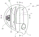
Fig. 6 is a bottom view of the golf club head of fig. 1 in a reference state.
Fig. 7 is a partially enlarged view of a region near the bottom portion surrounded by a broken line in fig. 3.
FIG. 8 is a schematic side cross-sectional view of the golf club head of FIG. 1.
FIG. 9 is a schematic cross-sectional side view of another golf club head according to the present invention.
Fig. 10 is a bottom view of another golf club head according to the present invention in a reference state.
FIG. 11 is a bottom view of another golf club head according to the present invention in a reference state.
Fig. 12A is a bottom view of another golf club head according to the present invention in a reference state.
Fig. 12B is a sectional view taken along line B-B of fig. 12A.
Fig. 12C is a cross-sectional view taken along line C-C of fig. 12A.
Fig. 13A is a bottom view of another golf club head according to the present invention in a reference state.
Fig. 13B is a cross-sectional view taken along line D-D of fig. 13A.
Fig. 13C is a cross-sectional view taken along line E-E of fig. 13A.
FIG. 14 is a bottom view of another golf club head according to the present invention in a reference state.
Description of the symbols
1: striking face
2: crown part
3: bottom part
10: the 1 st ditch
20: the 2 nd ditch
11: 1 st main inner wall
12: 1 st subsidiary inner wall
21: 2 nd subsidiary inner wall
22: 2 nd main inner wall
31: the 1 st grounding part
32: second grounding part
33: third grounding part
40: thick meat part
50: thick meat part
Detailed Description
Hereinafter, a golf club head according to some embodiments of the present invention will be described with reference to the drawings.
< 1. outline of Golf club head >
Fig. 1 is an oblique view of the golf club head, fig. 2 is a plan view of the head in a reference state, and fig. 3 is a sectional view taken along line a-a of fig. 2. As shown in fig. 1, the golf club head (hereinafter, also simply referred to as "head") 100 has a hollow structure having an internal space, and a face portion 1, a crown portion 2, a sole portion 3, and a hosel portion 5 form a wall face of the wood-type golf club head.
The striking surface portion 1 is a striking surface (フェース -side) having a striking surface, and the crown portion 2 is adjacent to the striking surface portion 1 to constitute an upper surface of the head. The sole 3 mainly constitutes the sole of the head, and the outer peripheral surface of the head 100 excluding the striking surface portion 1 and the crown portion 2. That is, in addition to the sole of the head 100, a portion extending from the toe side of the striking surface portion 1 to the heel side of the striking surface portion 1 through the back side of the head is also a part of the sole 3. The hosel portion 5 is a portion provided adjacent to the heel side of the crown 2, and has an insertion hole 51 into which a shaft (not shown) of a golf club is inserted. Further, the central axis Z of the insertion hole 51 coincides with the shaft axis.
Here, a reference state when the golf club head 100 is set on the ground will be described. First, the following states are defined as reference states: as shown in fig. 2 and 3, the plane P1 perpendicular to the ground H includes the central axis Z, and the head is placed on the ground at a predetermined lie angle and an actual loft angle. This plane P1 is referred to as a reference vertical plane. As shown in fig. 2, the direction of the intersection of the reference vertical plane P1 and the ground surface is referred to as the toe-heel direction, and the direction perpendicular to the toe-heel direction and parallel to the ground surface is referred to as the face-back direction.
In the present embodiment, the boundary between the striking face portion 1 and the crown portion 2 and the boundary between the striking face portion 1 and the sole portion 3 may be defined as follows. That is, when an edge line is formed between the both, the edge line is a boundary. On the other hand, when no clear ridge is formed, as shown in fig. 4A, in each of the cross sections E1, E2, and E3 … including the straight line N connecting the head center of gravity G and the Sweet Spot SS, as shown in fig. 4B, the curvature radius r of the face outer surface contour line Lf is defined as the edge of the face portion 1 at the position Pe of first 200mm from the Sweet Spot side toward the face outer side, and as the boundary with the crown portion 2 or the sole portion 3. The sweet spot SS is an intersection point between a normal line (straight line N) of a face (face surface) passing through the center of gravity G of the head and the face.
In addition, in the present embodiment, the boundary between the crown portion 2 and the sole portion 3 may be defined as follows. That is, when a ridge is formed between the crown portion 2 and the sole portion 3, the ridge is a boundary. On the other hand, in the case where a clear ridge line is not formed therebetween, the head is set in the reference state, and the outline thereof is observable from directly above the center of gravity of the head 100 as a boundary.
The head 100 may be made of, for example, a titanium alloy (Ti-6Al-4V) having a specific gravity of approximately 4.4 to 4.5. In addition to the titanium alloy, for example, 1 or 2 or more kinds of titanium alloy may be selected from stainless steel, maraging steel, aluminum alloy, magnesium alloy, amorphous alloy, and the like.
< 2. Assembly structure of golf club head
As shown in fig. 1 to 3, the golf club head 100 according to the present embodiment is configured by assembling a head body 101 having a crown 2 and a sole 3, and a striking face member 102 having a striking face portion 1 and an edge portion 15 extending from the edge thereof and formed in a cup shape. The head body 101 has an opening 18 defined by the crown 2 and sole 3, and is connected to a member 102 for a ball striking face which blocks the opening 18. That is, the end surface of the edge 15 of the face member 102 is butted against the end surface of the opening 18 of the head body 101, and they are joined by fusion (so-called cup-shaped face structure). Then, the member 102 for the ball-striking surface is integrated with the head body 101 by being attached to the opening 18 of the head body 101, whereby the edge 15 of the member 102 for the ball-striking surface functions as a part of the crown 2 and sole 3 of the head 100. Therefore, the face formed integrally by attaching the edge 15 of the ball striking face member 102 to the head body 101 constitutes the crown 2 and sole 3 of the head 100. Therefore, strictly speaking, the crown 2 and sole 3 of the head body 101 are parts of the crown 2 and sole 3 of the head 100, but in the present application, these are not distinguished, and the parts of the head body 101 may be simply referred to as the crown 2 and sole 3.
The head body 101 and the member for the ball striking surface 102 may be joined by welding (TIG (tungsten inert gas) welding, plasma welding, laser welding, brazing, or the like), for example. Such a head body 101 and the member 102 for the ball striking face may be manufactured by various methods. For example, the head body 101 may be manufactured by casting such as a known lost wax (lost wax) precision casting method. The member 102 for the ball-striking surface can be manufactured by, for example, forging, press working of a flat plate, casting, or the like. The component configuration of the head 100 described here is an example, and may be assembled by a plurality of components different from the example described here.
< 3. bottom Structure
Fig. 5 is a side view of the head 100 in a reference state, viewed from the toe side, fig. 6 is a bottom view of the head 100 in the reference state, and fig. 7 is a partial enlarged view of a region near the sole 3 surrounded by a broken line in fig. 3. As shown in fig. 5 to 7, the sole 3 is formed with 2 grooves recessed toward the inner space and extending substantially in parallel to the toe-heel direction. Here, the groove on the ball striking surface side is referred to as a 1 st groove 10, and the groove on the back side is referred to as a 2 nd groove 20. In addition, these grooves 10 and 20 are slightly curved so as to protrude to the back side in the bottom view.
As shown in fig. 5 to 7, the sole portion 3 has a band-shaped 1 st land portion 31 connected to the hitting surface portion 1 and extending in the toe-heel direction, and the 1 st groove 10 is connected to the back side of the 1 st land portion 31. The 1 st groove 10 is formed in a rectangular shape in a bottom view. The 1 st groove 10 is formed in a substantially triangular shape in a side sectional view by connecting a 1 st main inner wall 11 extending from the ball striking surface side and a 1 st sub inner wall 12 arranged on the back side of the 1 st main inner wall 11. That is, the 1 st main inner wall 11 extends from the end portion on the back side of the 1 st land portion 31 to the back side and is inclined upward (the crown portion 2 side). On the other hand, the 1 st sub inner wall 12 extends from the end portion on the back side of the 1 st main inner wall 11 toward the back side and is inclined downward. The length of the 1 st main inner wall 11 in the surface-back direction is longer than that of the 1 st sub inner wall 12, and most of the 1 st groove 10 is formed by the 1 st main inner wall 11. Hereinafter, a portion connecting the 1 st main inner wall 11 and the 1 st sub inner wall 12, i.e., a vertex portion having a triangular cross section, will be referred to as a 1 st vertex portion 13. The 1 st apex 13 is the deepest portion of the 1 st groove 10.
The bottom portion 3 is provided with a band-shaped 2 nd land portion 32 extending in the toe-heel direction on the back side of the 1 st groove 10. The 2 nd groove 20 is connected to the back side of the 2 nd land portion 32. The 2 nd groove 20 is formed in a substantially belt-like shape in a bottom view, and is longer in length in the toe-heel direction than the 1 st groove 10. That is, the first groove 10 is formed to extend on the toe side and the heel side. The 2 nd groove 20 is formed in a substantially triangular shape in a side sectional view by connecting a 2 nd sub inner wall 21 extending from the 2 nd land portion 32 and a 2 nd main inner wall 22 arranged on the back side of the 2 nd sub inner wall 21. That is, the 2 nd sub inner wall 21 extends from the end portion on the back side of the 2 nd land portion 32 to the back side and is inclined upward (the crown portion 2 side). On the other hand, the 2 nd main inner wall 22 extends from the end portion on the back side of the 2 nd sub inner wall 21 to the back side, and is inclined downward. The length of the 2 nd main inner wall 22 in the surface-back direction is longer than the 2 nd sub inner wall 21, and most of the 2 nd groove 20 is formed by the 2 nd main inner wall 22. Hereinafter, the portion of the 2 nd main inner wall 22 connected to the 2 nd sub inner wall 21, i.e., the apex portion having a triangular cross section, will be referred to as a 2 nd apex portion 23. The 2 nd top 23 is the deepest part of the 2 nd groove 20.
Further, a band-shaped 3 rd land portion 33 extending in the toe-heel direction is provided on the back surface side of the 2 nd groove 20. The 3 rd land portion 33 is in contact with the ground surface H in the reference state of the head 100 together with the 1 st land portion 31 and the 2 nd land portion 32. At this time, the 1 st land portion 31 and the 2 nd land portion 32 have flat surfaces almost parallel to the ground surface H in a side view, and the 3 rd land portion 33 contacts the ground surface only at an end edge on the surface side contacting the 2 nd groove 20. With this configuration, the head 100 is in contact with the floor surface H in the reference state at three points 1 to 3 rd land portions 31 to 33. Accordingly, when the golfer places the head 100 in the reference state, the head 100 is supported at a plurality of points on the ground H, and the head 10 is stabilized.
On the other hand, when the 1 st groove 10 is compared with the 2 nd groove 20, the following is shown. First, the 1 st crest 13 of the 1 st furrow 10 is located at a lower position than the 2 nd crest 23 of the 2 nd furrow 20. That is, as shown in fig. 7, the depth d1 of the 1 st groove 10 from the reference plane H is smaller than the depth d2 of the 2 nd groove 20. The length w1 of the 1 st groove 10 in the surface-back direction is longer than the length of the 2 nd groove 20 in the surface-back direction.
Further, in the sole portion 3, a recessed portion having a flat trapezoidal shape is formed in the vicinity of the substantially center in the toe-heel direction on the backrest surface side of the 2 nd groove 20, and the weight 60 is attached to the recessed portion and is detachable by a screw. Accordingly, the center of gravity of the head 100 is adjusted to be closer to the center of the back surface side, and further lowering of the center of gravity can be achieved.
< 4. feature >
According to the golf club head of the present embodiment, the following effects can be obtained.
<4-1>
As described above, the 1 st main inner wall 11 occupies most of the 1 st groove 10, and the 1 st main inner wall 11 extends to the back surface side and is inclined upward. On the other hand, in the 2 nd groove 20 located on the back side of the 1 st groove 10, the 2 nd main inner wall 22 occupies most of the groove, and the 2 nd main inner wall 22 extends toward the ball striking surface side and is inclined upward. Here, as shown in fig. 8, a virtual line V1 extending in the face-back direction along the 1 st main inner wall 11 and a virtual line V2 extending in the face-back direction along the 2 nd main inner wall 22 are set. In this way, since the virtual lines V1 and V2 intersect and are convex toward the inner space of the head 100, the 1 st groove 10 and the 2 nd groove 20 are formed in a mountain shape as a whole. Therefore, if the hitting force of the ball on the hitting surface portion 1 acts, the sole portion 3 is easily deformed to be recessed toward the inner space side by the mountain shape of the 1 st groove 10 and the 2 nd groove 20, and the rebound performance of the head 100 can be improved.
<4-2>
Here, the 1 st groove 10 and the 2 nd groove 20 are entirely mountain-shaped, but for example, it is conceivable that the grooves are formed without the 1 st sub inner wall 12 and the 2 nd sub inner wall 21 by directly connecting the 1 st main inner wall 11 and the 2 nd main inner wall 22, and if so, the grooves are entirely deep, which may prevent lowering of the center of gravity of the head 100. In contrast, in the present embodiment, the 1 st groove 10 and the 2 nd groove are divided, and one groove is made shallow to suppress the deepening of the entire groove, thereby realizing the low center of gravity of the head 100.
On the other hand, if the distance between the 1 st groove 10 and the 2 nd groove 20, that is, the length L3 (the length of the narrowest portion: see fig. 6) of the 2 nd land portion 32 in the surface-back direction is too large, there is a concern that: the bottom portion 3 is less likely to be deformed by the mountain shape. When the interval between the 1 st groove 10 and the 2 nd groove 20 is wide, the widths of the grooves 10 and 20 need to be made small, but there is a possibility that the bottom portion 3 is not easily deformed. On the other hand, if the length L3 is too small, stress may be concentrated when the 2 nd land portion 32 is deformed, and the strength of the bottom portion 3 may be reduced. From the above viewpoint, the length L3 is preferably 4mm or more and 15mm or less, for example.
<4-3>
In addition, in general, the striking face portion 1 is designed to have higher rigidity than the sole portion 3 because durability against impact at the time of striking is required. Therefore, in the vicinity of the striking face portion 1, there is a tendency that: the rigidity of the bottom portion 3 becomes high, and the bottom portion 3 is hard to deform. Therefore, as described above, if the 2 grooves 10, 20 are formed on the sole 3, the 1 st groove 10 located near the ball striking face portion 1 contributes to lowering the rigidity of the sole 3, but contributes less than the 2 nd groove 20 located closer to the back side. Therefore, in the present embodiment, the relationship between the depth d1 of the 1 st groove 10 and the depth d2 of the 2 nd groove 20 is d2 > d 1. That is, the 2 nd groove 20 located further toward the back surface side, which contributes to effectively reducing the rigidity, is formed relatively deeply, and the 1 st groove 10 located further toward the ball striking surface side, which contributes to effectively reducing the rigidity, is formed relatively shallowly. As a result, the rebound performance is effectively improved mainly by the 2 nd groove 20 on the back surface side, and the center of gravity position can be prevented from being increased by making the 1 st groove 10 on the ball striking surface side shallower. Namely, the center of gravity can be lowered.
<4-4>
The relationship between the length and depth of the grooves 10 and 20 in the surface-back direction may be set as follows. First, the 1 st groove 10 is preferably w1/d1 > 1, more preferably w1/d1 > 3, and still more preferably w1/d1 > 6. Under such conditions, the 1 st groove 10 is relatively long in the back-and-forth direction and shallow in the up-and-down direction. Accordingly, the originally contradictory 2 requirements of the improvement of the rebound performance of the sole 3 and the low center of gravity of the head 100 can be satisfied with good balance.
Similarly, the 2 nd groove 20 is preferably w2/d2 > 1, more preferably w2/d2 > 3, and still more preferably w2/d2 > 5. Under such conditions, the 2 nd trench 20 is relatively long in the front-rear direction and shallow in the vertical direction. Accordingly, as with the groove 10 of the 1 st part, the originally contradictory 2 requirements of the improvement of the rebound performance of the sole 3 and the low center of gravity of the head 100 can be satisfied with good balance. Further, by the above-mentioned relation, the 1 st trench 10 and the 2 nd trench 20 can be formed in a mountain shape as a whole, as explained in the above-mentioned < 4-1 >.
From the above viewpoint, it is preferably 15 mm. ltoreq. w 1. ltoreq.50 mm, preferably 5 mm. ltoreq. w 2. ltoreq.40 mm. In addition, it is preferably 0.3 mm. ltoreq. d 1. ltoreq.4 mm, preferably 0.5 mm. ltoreq. d 2. ltoreq.5 mm. Further, d2/w2 > d1/w1 is preferable.
In the present embodiment, the quantitative conditions for d1, d2, w1 and w2 are satisfied in all the regions in the toe-heel direction formed by the 1 st groove 10 and the 2 nd groove 20. However, these conditions may also be upright in the toe-heel direction. In this case, these conditions are preferably satisfied at least in the cross section perpendicular to the toe-heel direction through the ball striking surface center Fc, that is, the cross sections shown in fig. 3 and 6.
<4-5>
As described above, in the bottom portion 3, the 2 nd groove 20 disposed on the back side contributes more to the deformation. From this viewpoint, the position of the 2 nd groove 20 can be set as follows. First, as shown in fig. 6, in the reference state, the length of the head 100 in the face-back direction is set to L1, and the length in the face-back direction from the point on the frontmost side of the head 100 (the point at which the frontmost side is open from the front edge) to the edge on the ball striking surface side of the 2 nd groove 20 is set to L2 (see fig. 6). L1 is the length in the back-of-plane direction from the point on the forefront of the head 100 to the point on the rearmost of the head 100.
In this case, in the present embodiment, L2/L1 is preferably not less than 0.4, more preferably L2/L1 is not less than 0.45, and still more preferably L2/L1 is not less than 0.5. Accordingly, the 2 nd groove 20 is disposed closer to the rear surface side, and is less likely to be affected by the low deformability of the sole 3 due to the high rigidity of the striking face portion 1. As a result, the rebound performance of the bottom portion 3 can be effectively improved.
Further, L2/L1. ltoreq.0.8 is preferable, L2/L1. ltoreq.0.7 is more preferable, and L2/L1. ltoreq.0.6 is further preferable. Under such conditions, the 2 nd groove 20 does not excessively descend to the rear. That is, if groove 2 20 falls excessively rearward, i.e., if it is excessively far from the ball striking face, deformation at the time of striking becomes difficult in the vicinity of groove 2 20, and the amount of deflection in the vicinity of groove 2 20 may decrease. In addition, even if the 2 nd groove 20 is too close to the shell of the rear side of the head 100 where the rigidity is high, the amount of deflection in the vicinity of the 2 nd groove 20 may be reduced. Therefore, it is preferable that the 2 nd groove 20 is not excessively lowered to the rear side from the viewpoint of improving the rebound performance.
L2 is defined with reference to the edge on the striking surface side of the curved 2 nd groove 20, and therefore varies depending on the position in the toe-heel direction, but the numerical conditions described above in L2/L1 are satisfied in the present embodiment in all the regions in the toe-heel direction in which the grooves 20 are formed. However, the above numerical conditions may also be upright in the toe-heel direction. In this case, the numerical condition is preferably satisfied at least in a cross section perpendicular to the toe-heel direction through the face center Fc, that is, in the cross sections shown in fig. 3 and 8.
<4-6>
In the above embodiment, the 1 st groove 10 on the side closer to the ball striking surface is shallower. Accordingly, the following advantages are provided: when the golf club is swung, the sole 3 is less likely to collide with the floor H (lawn) and is likely to slide on the floor H.
<4-7>
On the one hand, the 2 nd groove 20 is formed over substantially the entire area in the toe-heel direction in the sole portion 3, and on the other hand, the 1 st groove 10 is formed only at a toe-off position in the toe-heel direction in the sole portion 3. That is, the 1 st groove 10 on the ball striking surface side is shorter than the 2 nd groove 20 on the back side in the toe-heel direction. As a result, the rebound performance is particularly improved at the toe side position where the 1 st groove 10 is formed. However, the position in the toe-heel direction where the 1 st groove 10 is formed is not limited to the example described here. That is, the 1 st groove 10 may be selectively formed at any position in the toe-heel direction where the rebound performance is intended to be particularly improved. However, as shown in fig. 10, 11, and 14 to be described later, the 1 st groove 10 may be formed over substantially the entire area in the toe-heel direction in the sole portion 3. In addition, the length of the 1 st groove 10 and the 2 nd groove 20 in the toe-heel direction may be increased or may be appropriately changed.
<4-8>
In the present embodiment, the 1 st groove 10 and the 2 nd groove 20 draw an arc (curved line) protruding toward the back side in the vicinity of the center in the toe-heel direction in the bottom view. As a result, the distance from the center Fc of the hitting surface, where the hitting points are concentrated, to the 1 st groove 10 can be set substantially equal over the entire area in the toe-heel direction of the 1 st groove 10. Similarly, the 2 nd groove 20 may be set so that the distance from the face center Fc to the 2 nd groove 20 is substantially equal over the entire area in the toe-heel direction of the 2 nd groove 20. Accordingly, the vicinities of the 1 st groove 10 and the 2 nd groove 20 are effectively deformed at the time of hitting a ball.
< 5. modification
Although the embodiments of the present invention have been described above, the present invention is not limited to the above embodiments, and various changes can be made without departing from the spirit thereof. For example, the following changes may be made. In addition, the following modifications may be combined as appropriate.
<5-1>
Although the 2 nd trench 20 may be formed deeper than the 1 st trench 10 in the above embodiment, the 1 st trench 10 may be formed deeper as shown in fig. 9. Even in this case, since the 1 st groove 10 and the 2 nd groove 20 are formed in a mountain shape as a whole, the bottom portion 3 is easily deformed by being recessed toward the internal space. As a result, the rebound performance of the head 100 can be improved.
<5-2>
In the above embodiment, the weight is disposed closer to the back surface side than the 2 nd groove 20, but the shape, number, and mounting position of the weight 60 are not limited. That is, the present invention is not limited to the example described above, and any number of weights 60 may be attached to any position according to the position of the center of gravity as a design target. For example, in the example of fig. 10, the weight 60 may be attached not only to the rear of the bottom portion 3 but also to the heel side in the 1 st furrow 10, and the center of gravity may be located closer to the heel side. In the example of fig. 11, the weight 60 is not attached to the rear of the sole portion 3, but the weight 60 is attached to the two 2 positions of the toe side and the heel side in the 1 st groove 10, whereby the center of gravity can be located closer to the hitting surface side. In the example of fig. 14 described later, the weight 60 located at the rear of the sole portion 3 may be attached to the heel side position in the 1 st groove 10 while slightly moving the weight 60 toward the toe side. The shape of the weight may be various shapes such as a circle and a polygon other than the planar trapezoidal shape.
<5-3>
In the golf club head according to the present invention, the thick-walled portion on the inner space side of the sole 3 may be formed. The thick portion may have various forms. For example, as shown in fig. 12A to 12C, a rib-arch-shaped fleshy portion 40 extending in the toe-heel direction may be formed near the center of the 1 st main inner wall 11 in the face-back direction. In the sole portion, the fleshy portion 40 extends over substantially the entire area in the toe-heel direction. In this example, the thick portion 40 extends linearly, but the thick portion 40 may be curved convexly to the back side along the shape of the 1 st groove 10, for example.
If such a thick portion 40 is provided, the increase in rigidity in the front-back direction becomes small, and therefore the rebound performance in the front-back direction can be substantially maintained. On the other hand, the thick flesh portion 40 can increase the rigidity of the sole portion 3 in the toe-heel direction, and therefore, the hitting sound can be increased.
The thick portion 40 is not limited to be formed on the 1 st main inner wall 11, and may be formed on the 2 nd main inner wall 22. The thick meat portion 40 may be provided at a plurality of positions.
In addition, a thick portion extending in the back-and-forth direction may be formed. For example, in the example shown in fig. 13A to 13C, the thick flesh portion 50 extending in the back-and-forth direction across both the 1 st trench 10 and the 2 nd trench 20 is formed. The thick-flesh portion 50 completely cuts off the 1 st furrow 10 from the 2 nd furrow 20. However, the thick-walled portion 50 may be configured to extend only at the position of the 1 st groove 10 and not to overlap with the position of the 2 nd groove 20.
Since the thick portion 50 is disposed at a toe-off position on the sole portion 3, the rigidity of the sole portion 3 can be increased on the toe side, and the rebound performance can be suppressed. On the other hand, at the position where the thick-walled portion is not provided in the toe-heel direction, the improvement of the rebound performance by the 1 st groove 10 and the 2 nd groove 20 can be maintained. The position in the toe-heel direction where the thick portion 50 is formed is not limited to the example described here, and the thick portion 50 may be selectively formed at any position in the toe-heel direction where the rebound performance is intended to be suppressed. In addition, such a thick meat portion 50 may be provided at a plurality of positions.
The thick portion 40 and the thick portion 50 may be formed as ribs of thin ribs as shown in the examples of fig. 12 and 13, or may be formed in a band shape wider than the ribs.
<5-4>
In the above embodiment, 3 grounding portions 31 to 33 grounded to the ground surface may be provided on the bottom portion, or any one of them may be omitted. For example, even if the 3 rd land portion 33 is omitted, the head 100 is stabilized by supporting the head 100 at 2 o' clock. In particular, the 1 st land portion 31 and the 2 nd land portion 32 are flat in a side sectional view and are in line contact with the ground H in the side sectional view. Therefore, the head 100 in the reference state is difficult to fall down in the forward and backward directions, and the head 100 in the reference state can be stabilized.
<5-5>
In the above embodiment, each of the grooves 10 and 20 is curved to be convex toward the back surface side, but either one or both of them may extend parallel to the toe-heel direction. Alternatively, as shown in fig. 14, a circular arc curved line may be drawn so that the vicinity of the center in the toe-heel direction protrudes toward the ball striking surface side. The same applies to the 2 nd groove 20.
<5-6>
In the present invention, the "main inner walls 11 and 22" of the grooves 10 and 20 are not particularly limited as long as the length in the surface-back direction is longer than 50% of the width (length) in the surface-back direction of the grooves 10 and 20, and the length is longer than the "sub inner walls 12 and 21", among the plurality of inner walls in which the grooves 10 and 20 are formed. For example, the inclination angles of the inner walls forming the 1 st groove 10 and the 2 nd groove 20 are not particularly limited, and the virtual line V1 along the 1 st main inner wall 11 and the virtual line V2 along the 2 nd main inner wall 22 may be convex toward the inner space of the head 100.
The main inner walls 11 and 22, the sub inner walls 12 and 21 may be formed by connecting a plurality of surfaces as long as they are inclined in the same direction. Further, other inner walls may be interposed between the main inner walls 11 and 12 and the sub inner walls 12 and 21. The angle of inclination of the inner wall between these is not particularly limited, and may be parallel to the ground, for example.
<5-7>
In the above embodiment, the number of the grooves formed in the bottom portion 3 is 2, but the number is not limited thereto, and may be 3 or more. In this case, the adjacent 2 grooves correspond to the 1 st and 2 nd grooves in the present invention.
<5-8>
In the above embodiment, the golf club head is defined as a driver type, but the type is not limited, and may be another wood type such as fairway wood, so-called multi-function type, hybrid type, or the like.
<5-9>
The striking surface member 102 may not be of a cup-shaped type, but may be of a plate type (plate type) in which the rim 15 is omitted, for example, and welded to an opening formed in the striking surface portion.
Claims (10)
1. A golf club head characterized in that,
the club head comprises: a ball striking face, crown and sole;
and having an interior space bounded by the striking face portion, crown portion and sole portion;
the bottom part is provided with a 1 st groove and a 2 nd groove which extend towards the toe-heel direction and are sunken towards the inner space side;
the 1 st groove is arranged closer to the ball striking surface than the 2 nd groove,
the 1 st groove has a 1 st main inner wall arranged on the ball striking surface side and a 1 st sub inner wall arranged on the back side;
the length of the 1 st main inner wall in the face-back direction is longer than that of the 1 st auxiliary inner wall, and the 1 st main inner wall inclines upwards towards the back side;
the 2 nd groove has a 2 nd sub inner wall arranged on the ball striking surface side and a 2 nd main inner wall arranged on the back side;
the length of the 2 nd main inner wall in the face-back direction is longer than that of the 2 nd auxiliary inner wall, and the 2 nd main inner wall inclines upwards towards one side of the hitting face;
at least a part of the toe-heel direction has a ratio of a length L2 in the face-back direction from a point on a foremost side of the golf club head to an edge on a ball striking surface side of the 2 nd groove, that is, L2/L1, of 0.4 or more with respect to a length L1 of the golf club head in the face-back direction in a reference state.
2. The golf club head of claim 1, wherein the 2 nd groove is deeper than the 1 st groove.
3. The golf club head according to claim 1 or 2,
the 1 st groove is formed by connecting a 1 st main inner wall arranged on the striking surface side and a 1 st auxiliary inner wall arranged on the back side;
the 2 nd groove is formed by connecting a 2 nd sub inner wall arranged on the striking surface side and a 2 nd main inner wall arranged on the back side.
4. The golf club head according to claim 1 or 2,
the bottom further comprises:
a 1 st land portion which is located closer to the ball striking surface side than the 1 st groove and which comes into contact with the ground surface when the bottom portion is provided on the ground surface;
a 2 nd ground contact portion which is located between the 1 st trench and the 2 nd trench and which comes into contact with the ground surface when the bottom portion is provided on the ground surface.
5. The golf club head according to claim 4, wherein the land portion 1 and the land portion 2 meet the ground surface in a line in a side cross-sectional view when the sole portion is provided on the ground surface.
6. The golf club head according to claim 4,
the bottom further has: and a 3 rd land portion which is located on the backrest surface side of the 2 nd groove and which comes into contact with the floor surface when the bottom portion is provided on the floor surface.
7. The golf club head according to claim 1 or 2, wherein the sole portion further has a fleshy portion extending in the toe-heel direction in at least 1 of the 1 st and 2 nd main inner walls.
8. The golf club head according to claim 1 or 2, wherein the sole further has a fleshy portion extending in a face-back direction at least at the position of the 1 st groove.
9. The golf club head according to claim 1 or 2, wherein the 1 st groove is shorter than the 2 nd groove in a toe-heel direction.
10. The golf club head according to claim 1 or 2, wherein at least one of the 1 st groove and the 2 nd groove extends convexly toward a back side in a plan view.
Applications Claiming Priority (2)
| Application Number | Priority Date | Filing Date | Title |
|---|---|---|---|
| JP2016138499A JP6790532B2 (en) | 2016-07-13 | 2016-07-13 | Golf club head |
| JP2016-138499 | 2016-07-13 |
Publications (2)
| Publication Number | Publication Date |
|---|---|
| CN107626087A CN107626087A (en) | 2018-01-26 |
| CN107626087B true CN107626087B (en) | 2021-05-04 |
Family
ID=60941869
Family Applications (1)
| Application Number | Title | Priority Date | Filing Date |
|---|---|---|---|
| CN201710570199.5A Active CN107626087B (en) | 2016-07-13 | 2017-07-13 | Golf club head |
Country Status (3)
| Country | Link |
|---|---|
| US (1) | US10543404B2 (en) |
| JP (1) | JP6790532B2 (en) |
| CN (1) | CN107626087B (en) |
Families Citing this family (4)
| Publication number | Priority date | Publication date | Assignee | Title |
|---|---|---|---|---|
| EP3897883B1 (en) * | 2018-12-21 | 2025-02-05 | Karsten Manufacturing Corporation | Golf club with adjustable weighting system |
| US11645561B2 (en) | 2019-03-18 | 2023-05-09 | International Business Machines Corporation | Question answering system influenced by user behavior and text metadata generation |
| EP4456992B1 (en) | 2022-01-12 | 2026-04-08 | Karsten Manufacturing Corporation | Golf club heads with slits and flexure inserts |
| USD1081876S1 (en) * | 2023-11-29 | 2025-07-01 | Sumitomo Rubber Industries, Ltd. | Weight for a golf club head |
Citations (4)
| Publication number | Priority date | Publication date | Assignee | Title |
|---|---|---|---|---|
| US5603668A (en) * | 1995-04-13 | 1997-02-18 | Antonious; Anthony J. | Iron type golf club head with improved sole configuration |
| JP2009178298A (en) * | 2008-01-30 | 2009-08-13 | Daiwa Seiko Inc | Golf club |
| CN204092983U (en) * | 2013-07-31 | 2015-01-14 | 邓禄普体育用品株式会社 | Glof club head |
| JP2015160137A (en) * | 2014-02-25 | 2015-09-07 | 美津濃株式会社 | Golf club head |
Family Cites Families (7)
| Publication number | Priority date | Publication date | Assignee | Title |
|---|---|---|---|---|
| US8235844B2 (en) * | 2010-06-01 | 2012-08-07 | Adams Golf Ip, Lp | Hollow golf club head |
| US7294064B2 (en) * | 2003-03-31 | 2007-11-13 | K.K Endo Seisakusho | Golf club |
| JP2010075531A (en) * | 2008-09-26 | 2010-04-08 | Globeride Inc | Golf club |
| US8758156B2 (en) * | 2009-05-13 | 2014-06-24 | Nike, Inc. | Golf club assembly and golf club with aerodynamic features |
| JP2013000184A (en) * | 2011-06-13 | 2013-01-07 | Bridgestone Sports Co Ltd | Golf club head |
| US10960273B2 (en) * | 2015-05-29 | 2021-03-30 | Karsten Manufacturing Corporation | Golf club head or other ball striking device having impact-influencing body features |
| US10245474B2 (en) * | 2014-06-20 | 2019-04-02 | Karsten Manufacturing Corporation | Golf club head or other ball striking device having impact-influencing body features |
-
2016
- 2016-07-13 JP JP2016138499A patent/JP6790532B2/en active Active
-
2017
- 2017-07-12 US US15/647,494 patent/US10543404B2/en active Active
- 2017-07-13 CN CN201710570199.5A patent/CN107626087B/en active Active
Patent Citations (4)
| Publication number | Priority date | Publication date | Assignee | Title |
|---|---|---|---|---|
| US5603668A (en) * | 1995-04-13 | 1997-02-18 | Antonious; Anthony J. | Iron type golf club head with improved sole configuration |
| JP2009178298A (en) * | 2008-01-30 | 2009-08-13 | Daiwa Seiko Inc | Golf club |
| CN204092983U (en) * | 2013-07-31 | 2015-01-14 | 邓禄普体育用品株式会社 | Glof club head |
| JP2015160137A (en) * | 2014-02-25 | 2015-09-07 | 美津濃株式会社 | Golf club head |
Also Published As
| Publication number | Publication date |
|---|---|
| CN107626087A (en) | 2018-01-26 |
| JP6790532B2 (en) | 2020-11-25 |
| US20180015336A1 (en) | 2018-01-18 |
| US10543404B2 (en) | 2020-01-28 |
| JP2018007825A (en) | 2018-01-18 |
Similar Documents
| Publication | Publication Date | Title |
|---|---|---|
| US10328319B2 (en) | Golf club head | |
| JP5315577B2 (en) | Iron golf club head and iron golf club | |
| JP5989509B2 (en) | Golf club head and golf club | |
| US10471311B2 (en) | Golf club head | |
| US20060217216A1 (en) | Fairway wood with titanium face member | |
| CN107626087B (en) | Golf club head | |
| US11235208B2 (en) | Golf club head | |
| US20150375068A1 (en) | Golf club head | |
| US10092806B2 (en) | Iron type golf club head | |
| CN107174805B (en) | Golf club head | |
| US10493333B2 (en) | Golf club head | |
| CN112169281B (en) | Golf club head and golf club | |
| US11213729B2 (en) | Golf club head | |
| CN107174806B (en) | Golf club head | |
| JP2009082291A (en) | Hollow golf club head | |
| JP5848839B1 (en) | Golf club head | |
| JP6731089B1 (en) | Golf club head | |
| US10449425B2 (en) | Golf club head | |
| JP7397955B2 (en) | golf club head | |
| JP2007089831A (en) | Golf club head | |
| JP2024101694A (en) | Golf Club Head | |
| JP2004147756A (en) | Wood type golf club head and wood type golf club |
Legal Events
| Date | Code | Title | Description |
|---|---|---|---|
| PB01 | Publication | ||
| PB01 | Publication | ||
| TA01 | Transfer of patent application right |
Effective date of registration: 20180517 Address after: Kobe City, Japan's Hyogo central flank Bang town 3 chome 6 No. 9 Applicant after: Sumitomo Rubber Industries, Ltd. Address before: Kobe City, Hyogo Prefecture, Japan Central flank Bang Cho 3 chome 6 No. 9 Applicant before: Dunlop Sports Co., Ltd. |
|
| TA01 | Transfer of patent application right | ||
| SE01 | Entry into force of request for substantive examination | ||
| SE01 | Entry into force of request for substantive examination | ||
| GR01 | Patent grant | ||
| GR01 | Patent grant |