Detailed Description
Embodiment 1.
First, a network structure of the present invention will be explained.
Fig. 1 is a diagram showing the configuration of a network according to embodiment 1. The network is a multihop network constituted by nodes 10a to c as wireless communication devices and a gateway 11. The network in fig. 1 is a tree-structured network having a gateway 11 as a root. The gateway 11 constructs and manages a network, and transmits and receives data to and from a node directly or via another node. In addition, data is transmitted and received between the gateway 11 and a higher-order device and/or other network connected to the gateway 11.
The direction from the node to the gateway 11 is an upstream direction, and the direction from the gateway 11 to the node is a downstream direction. In fig. 1, a link connected to a gateway 11 via a node 10a, a node 10b, a node 10c, and other nodes is constructed. The node 10a is a lower node of the nodes 10b and 10 c. The node 10b is a lower node of the node 10c and an upper node of the node 10 a. The node c is a superordinate node of the nodes a and b. In addition, the nodes 10a to c perform intermittent control. The nodes 10 a-c periodically repeat the activation and the deactivation. The nodes 10a to c may be started at a time close to the expiration date of the link information.
Next, the structure of the node 10 will be explained. The nodes 10a to c have the same configuration as the node 10.
Fig. 2 is a block diagram showing the structure of the node 10 of embodiment 1.
The node 10 is composed of an antenna 21, a radio transmitting/receiving unit 22, an application data transmitting/receiving unit 23, a network control unit 24, and an intermittent control unit 25. The network control unit 24 is composed of an uplink management unit 26 and a downlink management unit 27. The intermittent control unit 25 is composed of a node management unit 28 and a start-up management unit 29. A sensor may be connected to the node 10, and the application data transmitting/receiving unit 23 may transmit and receive data to and from the sensor.
First, a case where the node 10 receives data will be described.
When receiving a radio signal from another node, the antenna 21 outputs the radio signal to the radio transmitting/receiving unit 22. The wireless transmitter/receiver 22 converts the wireless signal into a frame and confirms the destination address of the frame. In the frame, two kinds of addresses, a network address and a MAC address, are set as destination addresses. The network address is the destination address of the data sent by the frame. The MAC address is a destination address showing the next node on the multi-hop link. The network address and the MAC address may be values that can uniquely identify the node. In addition, as with the destination address, a source network address and a source MAC address are set in the frame for the source.
The radio transceiver 22 outputs the data to the application data transceiver 23 or the network controller 24 according to the content of the data to be transmitted in the frame. The application data transmitting/receiving unit 23 processes the application data input from the wireless transmitting/receiving unit 22. When the link control message is input from the radio transmitter/receiver 22, the network controller 24 updates the link information.
The uplink management unit 26 associates and holds the MAC address of the upper node, the level information, the MAC address of the next node, and the validity period of the link information. The level information refers to a value indicating the distance from the gateway 11 to the node. The distance is expressed, for example, in hop count. The hop count is the number of nodes through until the node of the target address. The MAC address of the next node is the next node of the link when transmitting data addressed to the upper node, and is a node adjacent to the node 10. The uplink management section 26 stores the transmission source MAC address of the uplink control message as the MAC address of the next node. The MAC address of the upper node, the level information, and the validity period of the link information are values notified by the uplink control message.
The downlink management unit 27 associates and holds the MAC address of the lower node, the rank information, the MAC address of the next node, and the validity period of the link information. The next node is a node next to the link when transmitting data addressed to the lower node, and is a node adjacent to the node 10. The downlink management section 27 stores the transmission source MAC address of the downlink control message as the MAC address of the next node. The validity periods of the MAC address, the class information, and the link information of the lower node are values notified by the downlink control message.
The uplink management unit 26 and the downlink management unit 27 may hold link information of a plurality of nodes.
The node management unit 28 associates and holds the MAC address of the adjacent node with whether or not each node is performing intermittent control. When the node joins the network, whether to carry out MAC address and intermittent control of the node is sent to the surrounding nodes. The node management unit 28 can grasp whether or not the adjacent node is performing intermittent control based on the information at this time.
Further, the start management unit 29 holds the intermittent cycle of the own node.
Next, a case where the node 10 transmits data will be described.
The application data transmitter/receiver 23 outputs application data generated by a sensor and/or an application connected to the node 10 to the wireless transmitter/receiver 22. The radio transmission/reception unit 22 inquires of the node management unit 28 whether or not the next node is performing intermittent control. When the next node is performing intermittent control, the radio transceiver 22 transmits application data to the next node via the antenna 21 when receiving a data request from the next node. When the next node does not perform the intermittent control, the wireless transmission/reception unit 22 transmits data to the next node without waiting for the reception of the data request.
Next, a case where the node 10 transmits a link control message will be described.
The network control unit 24 refers to the uplink management unit 26 or the downlink management unit 27, adds information of its own node, and generates a link control message. The uplink control message is composed of the MAC address of the upper node, the class information, and the validity period of the link. The network control unit 24 sets the MAC address of the own node among the MAC addresses of the upper nodes as the link information of the own node. The network control unit 24 holds the level information of the own node and the validity period of the link, and sets the held values for the uplink control message. The network control unit 24 outputs the generated uplink control message and the MAC address of the next node to the radio transmission/reception unit 22. The radio transmitting/receiving unit 22 transmits the uplink control message to the lower node via the antenna 21 in a broadcast manner.
The downlink control message is composed of the MAC address of the lower node, the class information, and the validity period of the link. The network control unit 24 sets the MAC address of the own node among the MAC addresses of the lower nodes as the link information of the own node. The network control unit 24 holds the level information of the own node and the validity period of the link, and sets the held values to the downlink control message. The network control unit 24 outputs the generated downlink control message and the MAC address of the next node to the radio transmission/reception unit 22. The radio transmitter/receiver unit 22 transmits the downlink control message to the upper node in a unicast manner via the antenna 21.
When transmitting the link control message, the radio transmission/reception unit 22 transmits the link control message without inquiring the node management unit 28 whether or not the next node is performing intermittent control.
Next, the operation of the node 10 receiving data from another node will be described in detail.
Fig. 3 is a flowchart showing a flow of reception processing of the node 10 according to embodiment 1.
The wireless transmitter/receiver 22 starts the process from step S301 when receiving a wireless signal from the antenna 21.
In step S301, the radio transceiver unit 22 determines whether or not the data to be transmitted to the frame is addressed to its own node. In the case where the target network address of the frame is the own node, the processing proceeds to step S302.
In step S302, the radio transceiver 22 determines whether or not the data to be transmitted as a frame is application data. When the data transmitted in the frame is application data, the radio transceiver 22 outputs the application data to the application data transceiver 23.
In step S303, the application data transmitting/receiving unit 23 processes the input application data. The application data transmitting/receiving unit 23 may further output data to a sensor connected to the own node. The process is ended.
In step S302, in the case where the data transmitted by the frame is not the application data, the process proceeds to step S304.
In step S304, when the data to be transmitted is a link control message, the radio transceiver unit 22 outputs the link control message to the network controller unit 24.
In step S305, the network control unit 24 updates the link information. Details of the processing in step S305 will be described later. The process is ended.
In step S304, when the data to be transmitted by the frame is not a link control message, the radio transmission/reception unit 22 performs processing corresponding to the content of the message, and the processing ends.
In step S301, in the case where the target network address of the frame is not the own node, the processing proceeds to step S306. This is the case when the frame is forwarded to other nodes.
In step S306, in the case where the destination MAC address of the frame is the own node, the process proceeds to step S307.
In step S307, the wireless transceiver 22 transfers the data received from the other node to the next node. The details of the processing will be described later.
In step S306, if the destination MAC address of the frame is not the own node, the process proceeds to step S308.
In step S308, the radio transmission/reception unit 22 discards the frame. The process is ended.
Next, the details of the processing in step S305 in fig. 3 will be described. In step S305, the network control unit 24 updates the link information.
Fig. 4 is a flowchart showing a flow of the link information update process of the node 10 according to embodiment 1.
The radio transceiver unit 22 starts the process when receiving the link control message.
In step S401, the radio transmitter/receiver unit 22 transmits an acknowledgement to the node that transmitted the link control message via the antenna 21. The radio transceiver 22 also outputs a link control message to the network controller 24.
In step S402, the network control unit 24 determines whether or not the uplink control message is input. When the uplink control message is input, the process proceeds to step S403.
In step S403, the network control unit 24 stores the link information in the uplink management unit 26.
In step S402, if no uplink control message is input, then a downlink control message is input, and the process proceeds to step S404.
In step S404, the network control unit 24 stores the link information in the downlink management unit 27.
Next, the operation of the node 10 to transmit application data to another node will be described in detail.
Fig. 5 is a flowchart showing a flow of transmission processing of the node 10 according to embodiment 1. Although the explanation is given when data generated by the node 10 is transmitted, the processing of the flowchart is also performed when data received from another node is transferred. When forwarding data received from other nodes, it is step S307 of fig. 3.
The application data transmitting/receiving unit 23 transmits the application data to another node by processing according to the input from the sensor and/or the received application data. The application data transceiver 23 outputs the application data and the destination network address to the radio transceiver 22.
When the data transmitted from the application data transmitter/receiver 23 is input, the wireless transmitter/receiver 22 starts the process from step S501.
In step S501, the radio transceiver unit 22 outputs the destination network address to the network control unit 24, and inquires of the next node. The network control unit 24 outputs the MAC address of the next node corresponding to the destination network address to the radio transmission/reception unit 22. The radio transceiver 22 sets the destination network address input from the application data transceiver 23 as the destination network address of the frame. The radio transceiver 22 sets the MAC address of the next node input from the network controller 24 as the destination MAC address of the frame.
In step S502, the radio transmission/reception unit 22 outputs the MAC address of the next node to the intermittent control unit 25, and inquires whether the next node is performing intermittent control. The intermittent control unit 25 refers to the node management unit 28, and outputs to the radio transmission/reception unit 22 whether or not the next node is in intermittent control. In the case where the next node is in the intermittent control, the process proceeds to step S503. Further, in a case where the next node is not in the intermittent control, the process proceeds to step S504.
In step S503, the radio transceiver unit 22 waits until receiving a data request from the next node. When the wireless transmission/reception section 22 receives a data request from the next node, the process proceeds to step S504.
In step S504, the wireless transceiver unit 22 sets the MAC address of the next node to the destination MAC address of the frame, and sets the application data to the data portion of the frame. The radio transmitting/receiving unit 22 converts the frame into a radio signal and outputs the radio signal to the antenna 21. The antenna 21 transmits the wireless signal to the next node. The process is ended.
Next, the operation of the network control unit 24 for transmitting the downlink control message will be described in detail.
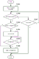
Fig. 6 is a flowchart showing a flow of a transmission process of a downlink control message by the node 10 according to embodiment 1.
When the time comes to transmit the downlink control message, the network control unit 24 starts the process from step S601. The network control unit 24 may transmit the downlink control message periodically, or may transmit the downlink control message at a time close to the expiration date of the downlink control message or at a time when the node 10 is activated.
In step S601, the network control unit 24 refers to the downlink management unit 27, generates a downlink control message, and outputs the downlink control message to the radio transceiver unit 22 together with the MAC address of the destination node. The transmission destination node is an adjacent upper node. The wireless transmitting and receiving section 22 sets a downlink control message in the data portion of the frame, converts the frame into a wireless signal, and transmits the wireless signal to the transmission destination node via the antenna 21.
In step S602, the radio transceiver unit 22 determines whether or not a transmission acknowledgement is received from the node that transmitted the link control message. When the delivery acknowledgement is received, the radio transceiver 22 notifies the network controller 24 of the reception of the delivery acknowledgement, and proceeds to step S603.
In step S603, the network control unit 24 starts a timer. The length of the timer is set to a time obtained by subtracting the time taken for the link information update from the time until the next node 10 goes to sleep.
In step S604, the network control unit 24 determines whether or not the timer has expired. In the case where the timer has expired, the process proceeds to step S605. In the case where the timer has not expired, the process returns to step S604.
In step S605, the network control unit 24 updates the validity period of the link information held by the uplink management unit 26. When the uplink management unit 26 holds a plurality of pieces of link information, the validity period of the uplink information having the transmission destination of the downlink control message as the next node is updated. This is because, by receiving a delivery acknowledgement from the transmission destination node of the downlink control message, it is confirmed that the uplink with the transmission destination node of the downlink control message as the next node is valid. The process is ended.
In step S602, if the delivery confirmation is not received, the process proceeds to step S606. In step S606, when the radio transceiver unit 22 determines that the transmission of the downlink control message has failed, the process ends. When the radio transmitter/receiver unit 22 determines that the transmission of the downlink control message has not failed, the process returns to step S602. The failure to transmit the downlink control message refers to, for example, a case where the reception waiting time for the acknowledgement has arrived, and a case where the acknowledgement cannot be received even if the retransmission of the downlink control message has reached a predetermined number of times.
Next, the timing of updating the link will be explained. For simplicity of description, the operation will be described with the device name as the main body.
Fig. 7 is a timing chart showing an uplink of the update node 10a and a downlink of the node 10b of embodiment 1.
The node 10a transmits a downlink control message to the node 10b in a unicast manner (S701). The node 10b transmits an acknowledgement to the node 10a (S702), and updates the downlink information (S703). When the node 10a receives an acknowledgement of delivery for transmission of the downlink control message from the node 10b, a timer is started (S704). In the case where the uplink control information has not been received until the timer expires, the node 10a updates the validity period of the uplink information with the node 10b as the next node (S705). The length of the timer is set to a time obtained by subtracting a time taken for updating of the link information from a time until the node 10 makes a sleep next. In the case where an uplink control message is received from node 10b before the timer expires, node 10a updates the uplink information by saving the contents of the message to the uplink information.
In the present embodiment, the network control unit 24 holds the validity period of the uplink by the uplink management unit 26, but may not hold it. When the delivery acknowledgement is received, it is determined that the link information having the transmission source node of the delivery acknowledgement as the next node is valid, and the link information is held. When the link information is determined to be invalid, the link information may be deleted.
Next, a hardware configuration of the node 10 will be explained.
Fig. 8 is a block diagram showing an example of the hardware configuration of the node 10 according to embodiment 1.
The node 10 is made up of a memory 81, a processor 82 and a wireless communication device 83. The wireless communication device 83 is connected to the antenna 21.
The memory 81 stores programs and data for realizing the functions of the radio transmission/reception unit 22, the application data transmission/reception unit 23, the network control unit 24, and the intermittent control unit 25. The memory 81 also stores data for realizing the functions of the uplink management unit 26, the downlink management unit 27, the node management unit 28, and the startup management unit 29. The Memory is composed of, for example, a ROM (Read Only Memory), a RAM (Random Access Memory), an HDD (Hard Disk Drive), and an SSD (Solid State Drive).
The processor 82 reads the program and data stored in the memory 81 to realize the functions of the radio transmitting/receiving unit 22, the application data transmitting/receiving unit 23, the network control unit 24, and the intermittent control unit 25. The processor 82 is realized by a processing circuit such as a CPU, a system LSI (Large Scale Integration), or the like that executes a program stored in a memory.
Further, the functions of the radio transmission/reception unit 22, the application data transmission/reception unit 23, the network control unit 24, and the intermittent control unit 25 may be executed by cooperation of a plurality of processing circuits.
The wireless communication device 83 realizes the functions of the wireless transmission/reception section 22 together with the memory 81 and the processor 82. The wireless communication device 83 is constituted by a wireless transmitting device and a wireless receiving device, and transmits and receives wireless signals with other apparatuses by means of wireless lines.
Further, although the description has been given of whether or not intermittent control is performed when a node joins the network and is transmitted to a peripheral node, the intermittent control may be added to an uplink control message, a downlink control message, application data, an acknowledgement, or the like and transmitted.
In the network of fig. 1, a node that performs intermittent control and a node that does not perform intermittent control may coexist. For example, in a case of a system in which data of heat generated from a plurality of production apparatuses is collected in a Factory having a Factory Automation (FA) system, a node that performs intermittent control and a node that does not perform intermittent control may coexist. Depending on the position where the node is provided, there are cases where power can be supplied and cases where power cannot be supplied. Intermittent control is performed to reduce power consumption of nodes that cannot supply power.
Therefore, in the present embodiment, a wireless communication apparatus that forms a multi-hop network having a tree structure and repeats activation and sleep includes: a network control unit that holds downlink information, which is information of a link to a radio communication apparatus lower than the network control unit in the tree structure, and uplink information, which is information of a link to a radio communication apparatus higher than the network control unit in the tree structure, and generates a downlink control message for notifying the downlink information; and a radio transmitting/receiving unit that instructs the network control unit to update the uplink information when a transmission acknowledgement for the downlink control message is received from an upper adjacent radio communication device after the downlink control message is transmitted to the upper adjacent radio communication device in the tree structure, so that the communication link can be updated even when the radio communication device constituting the multihop network is performing intermittent control. By updating the uplink information if an acknowledgement for the downlink control message is received, the uplink information can be updated even if the uplink control message is not received until the sleep is performed due to the intermittent period.
Embodiment 2.
Although embodiment 1 described above updates uplink information by receiving an acknowledgement of a downlink control message, this embodiment shows an embodiment in which an uplink control message is transmitted when a downlink control message is received.
In this embodiment, a portion different from embodiment 1 will be described.
Next, the details of the operation of the network control unit 24 to transmit the uplink control message when receiving the downlink control message will be described.
Fig. 9 is a flowchart showing the flow of a downlink control message reception process and an uplink control message transmission process of the node 10 according to embodiment 2.
When the radio transmitter/receiver 22 receives the downlink control message, the process starts from step S901.
In step S901, the radio transceiver unit 22 transmits a transmission acknowledgement to the source node of the downlink control message, and outputs the downlink information to the network controller 24.
In step S902, the network control unit 24 stores the input downlink information in the downlink management unit 27, and updates the link information.
In step S903, the network control unit 24 determines whether or not uplink information is held by referring to the uplink management unit 26. If the uplink information is not held, the process proceeds to step S904.
In step S904, the network control unit 24 generates an uplink control message and outputs the uplink control message to the radio transmission/reception unit 22. The radio transmitter/receiver 22 transmits the input uplink control message in a broadcast manner. The process is ended.
In step S903, if the uplink information is not held, the process proceeds to step S905. The network control unit 24 generates an uplink control message to which contents not holding uplink information are added, and outputs the uplink control message to the radio transmission/reception unit 22. The radio transmitter/receiver 22 transmits the input uplink control message in a broadcast manner. The process is ended.
Further, although the content not holding the uplink information is added to the uplink control message, it may be added to another message such as an uplink search message for searching the uplink and transmitted.
Next, the operation of the network control unit 24 for receiving the uplink control message will be described in detail.
Fig. 10 is a flowchart showing a flow of a process of receiving an uplink control message by the node 10 according to embodiment 2.
When the radio transmitter/receiver 22 receives the uplink control message, the process starts at step S1001.
In step S1001, the radio transceiver unit 22 outputs the uplink information to the network controller unit 24.
In step S1002, if there is information in the uplink information, the process proceeds to step S1003.
In step S1003, the network control unit 24 stores the input uplink information in the uplink management unit 26 and updates the link information.
In step S1002, when there is no uplink information, the network control unit 24 updates the uplink information of the uplink management unit 26 and searches for another uplink. The process is ended.
Next, the timing of updating the link will be explained. For simplicity of description, the operation will be described with the device name as the main body.
Fig. 11 is a sequence diagram showing an uplink of the update node 10a and a downlink of the node 10b in embodiment 2.
The node 10a transmits a downlink control message to the node 10b in a unicast manner (S1101). The node 10b transmits a delivery acknowledgement to the node 10a (S1102), and updates the downlink information (S1103). The node 10b transmits the uplink control message in a broadcast manner (S1104). On the other hand, when the node 10a receives the delivery acknowledgement for the transmission of the downlink control message from the node 10b, the timer is started (S1105). Receiving the uplink control information until the timer expires, the node 10a updates the uplink information (S1106).
Therefore, in the present embodiment, the network control unit generates an uplink control message for notifying information on the uplink, and when the radio transmission/reception unit receives a downlink control message from an adjacent radio communication device lower than the own device in the tree structure, the radio transmission/reception unit instructs the network control unit to update the downlink information and transmits the uplink control message to the adjacent radio communication device lower than the own device. Further, even if the node that transmits the uplink control message does not know the timing at which the node that transmitted the downlink control message starts, the uplink information can be updated.
Further, when the network control unit does not hold uplink information, it generates an uplink control message indicating the content of the information that does not hold uplink, and when the radio transmission/reception unit receives a downlink control message from an adjacent radio communication device lower than the own device in the tree structure, it transmits the uplink control message to the adjacent radio communication device lower than the own device.
Embodiment 3.
In embodiment 2 above, the uplink control message is transmitted when the downlink control message is received, but in the present embodiment, an embodiment is shown in which whether or not to transmit the uplink control message is determined depending on whether or not the transmission source node of the downlink control message is performing intermittent control.
In this embodiment, a description will be given of a portion different from embodiment 2.
The details of the operation of the network control unit 24 to transmit the uplink control message when receiving the downlink control message will be described.
Fig. 12 is a flowchart showing the flow of a downlink control message reception process and an uplink control message transmission process of the node 10 according to embodiment 3. The processing in steps S1201 to S1203, and S1206 is the same as the processing in steps S901 to S903, and S905 in fig. 9, and therefore, the description thereof is omitted.
In step S1203, when the network control unit 24 holds the uplink information, the process proceeds to step S1204.
In step S1204, the network control unit 24 inquires of the node management unit 28 of the intermittent control unit 25 whether or not the node 10a is performing intermittent control. When the node 10a is performing the intermittent control, the network control unit 24 generates an uplink control message and outputs the uplink control message to the radio transmission/reception unit 22. The radio transmitter/receiver 22 transmits the input uplink control message in a broadcast manner. In the case where the node 10a does not perform intermittent control, the processing ends.
Therefore, in the present embodiment, the intermittent control unit is provided which holds information on whether or not the adjacent wireless communication device performs intermittent control, and when the next-lower adjacent wireless communication device performs intermittent control, the wireless transmission/reception unit transmits the uplink control message to the next-lower adjacent wireless communication device when receiving the downlink control message from the next-lower adjacent wireless communication device.
Embodiment 4.
In the above embodiment 3, whether or not to transmit an uplink control message is determined according to whether or not the transmission source node of the downlink control message is performing intermittent control, but this embodiment shows an embodiment in which a downlink control message is transmitted upon receiving an uplink control message.
In this embodiment, a description will be given of a portion different from embodiments 1 to 3.
The operation of the network control unit 24 for receiving the uplink control message will be described in detail.
Fig. 13 is a flowchart showing the flow of the transmission process of the uplink control message and the reception process of the downlink control message by the node 10 of embodiment 4.
When the time comes to transmit the uplink control message, the network control unit 22 starts the process from step S1301. The network control unit 24 may transmit the uplink control message periodically, or may transmit the uplink control message at a time close to the expiration date of the uplink control message or at a time when the node 10 is started.
In step S1301, the network control unit 24 refers to the uplink management unit 26, generates an uplink control message, and outputs the uplink control message to the radio transceiver unit 22 together with the MAC address of the destination node. The transmission destination node is an adjacent lower node. The radio transmission/reception section 22 sets an uplink control message for the data portion of the frame, converts the frame into a radio signal, and transmits the radio signal to the transmission destination node via the antenna 21.
In step S1302, the radio transceiver unit 22 receives a delivery acknowledgement from the node that transmitted the uplink control message. The radio transceiver 22 notifies the network controller 24 of the reception of the delivery acknowledgement.
In step S1303, the network control unit 24 starts a timer. The length of the timer is set to a time obtained by subtracting a time taken for updating the link information from a time until the next node 10 goes to sleep.
In step S1304, the radio transceiver unit 22 determines whether or not the downlink control message has been received. If it has been received, the process proceeds to step S1305.
In step S1305, the radio transmitter/receiver 22 outputs the downlink control message to the network controller 24. The network control unit 24 updates the downlink. The process is ended.
In step S1304, in the case where the downlink control message has not been received, the process proceeds to step S1306.
In step S1306, the network control unit 24 determines whether or not the timer has expired. In the case where the timer has expired, the process ends. In the case where the timer has not expired, the process returns to step S1304.
Next, the details of the operation of transmitting the downlink control message when the network control unit 24 receives the uplink control message will be described.
Fig. 14 is a flowchart showing the flow of the uplink control message reception process and the downlink control message transmission process of the node 10 according to embodiment 4.
When the radio transmission/reception unit 22 receives the uplink control message, the process starts from step S1401.
In step S1401, the radio transceiver unit 22 transmits an acknowledgement to the source node of the uplink control message, and outputs uplink information to the network control unit 24.
In step S1402, the network control unit 24 stores the input uplink information in the uplink management unit 26 and updates the uplink information.
In step S1403, the network control unit 24 generates a downlink control message with reference to the downlink management unit 27, and outputs the downlink control message to the radio transmission/reception unit 22. The radio transmitter/receiver unit 22 transmits the input downlink control message in a unicast manner. The process is ended.
Next, the timing of updating the link will be explained. For simplicity of description, the operation will be described with the device name as the main body.
Fig. 15 is a sequence diagram showing an uplink of the update node 10a and a downlink of the node 10b of embodiment 4.
The node 10b transmits an uplink control message in a broadcast manner (S1501). The node 10b starts a timer (S1502). The node 10a receives the uplink control message and updates the uplink information (S1503). The node 10a transmits a downlink control message to the node 10b in a unicast manner (S1504). The node 10b transmits an acknowledgement to the node 10a (S1505), and updates the downlink information (S1506). In this case, the node 10b updates the downlink information before the timer expires.
The node 10b may transmit an uplink control message to the node 10a, the uplink control message including information requesting the content of the downlink information. In the case where information requesting the content of the downlink information has been attached to the uplink control message, the node 10a may transmit the downlink control message to the node 10 b.
Therefore, in the present embodiment, when the radio transmitter/receiver unit receives an uplink control message from a higher-order adjacent radio communication apparatus, the radio transmitter/receiver unit instructs the network control unit to update the uplink information and transmits a downlink control message to the higher-order adjacent radio communication apparatus. Further, even if the node that transmits the downlink control message does not know the time when the node that transmitted the uplink control message starts up, the downlink information can be updated.
Further, since the network control unit generates an uplink control message for notifying information on an uplink and the radio transmission/reception unit includes information on a downlink held by a radio communication device adjacent to the network control unit and lower than the network control unit in the request tree structure in the uplink control message and transmits the information to the radio communication device adjacent to the network control unit, the downlink can be reliably updated while the node that transmitted the uplink control message is activated.
Embodiment 5.
Although embodiment 4 described above is configured to transmit a downlink control message when an uplink control message is received, this embodiment shows an embodiment in which uplink information is included in an acknowledgement when a downlink control message is received.
In this embodiment, a description will be given of a portion different from embodiments 1 to 4.
The operation of the network control unit 24 for transmitting the downlink control message will be described in detail.
Fig. 16 is a flowchart showing the flow of the transmission processing of the downlink control message by the node 10 according to embodiment 5. The processing in steps S1601 to S1602, and S1604 to S1607 is the same as the processing in steps S601 to S606 in fig. 6, and therefore, the description thereof is omitted.
In step S1602, when the radio transceiver unit 22 receives an acknowledgement from the node that transmitted the link control message, the process proceeds to step S1603.
In step S1603, the radio transceiver unit 22 determines whether or not uplink information is added to the transmission confirmation. When the uplink information is added to the delivery acknowledgement, the radio transceiver unit 22 notifies the network control unit 24 of the content of the received delivery acknowledgement and the uplink information, and the process proceeds to step S1606. If the uplink information is not added to the delivery acknowledgement, the radio transceiver unit 22 notifies the network controller 24 of the receipt of the delivery acknowledgement, and the process proceeds to step S1604.
The processing after step S1604 is the same as steps S603 to S605 of fig. 6. The process is ended.
Next, the operation of the network control unit 24 for receiving the downlink control message will be described in detail.
Fig. 17 is a flowchart showing a flow of a downlink control message reception process of the node 10 of embodiment 5.
When the radio transceiver unit 22 receives the downlink control message, the process starts at step S1701.
In step S1701, the radio transceiver unit 22 acquires uplink information from the uplink management unit 26 of the network control unit 24. The radio transmission/reception unit 22 adds uplink information to the acknowledgement, and transmits the acknowledgement to the transmission source node of the downlink control message. The uplink information added to the acknowledgement is, for example, information of the expiration date.
In step S1702, the radio transceiver unit 22 outputs the downlink information to the network controller 24. The network control unit 24 stores the input downlink information in the downlink management unit 27, and updates the link information. The process is ended.
Next, the timing of updating the link will be explained. For simplicity of description, the operation will be described with the device name as the main body.
Fig. 18 is a sequence diagram showing an uplink of the update node 10a and a downlink of the node 10b in embodiment 5.
The node 10a transmits a downlink control message to the node 10b in a unicast manner (S1801). The node 10b transmits an acknowledgement and uplink information to the node 10a (S1802), and updates the downlink information (S1803). The node 10a updates the uplink information (S1804)
Therefore, in the present embodiment, when the radio transceiver unit receives a downlink control message from an adjacent radio communication device lower than the radio communication device itself in the tree structure, the radio transceiver unit acquires uplink information from the network control unit and transmits the uplink information to the adjacent radio communication device lower than the radio communication device including the transmission acknowledgement. In addition, the time for starting up the node that has transmitted the downlink control message can be reduced.
Description of the reference symbols
10. 10a to c: a node;
11: a gateway;
21: an antenna;
22: a wireless transmitting/receiving unit;
23: an application data transmitting/receiving unit;
24: a network control unit;
25: an intermittent control section;
26: an uplink management unit;
27: a downlink management unit;
28: a node management unit;
29: a start management unit;
81: a memory;
82: a processor;
83: a wireless communication device.