CN107531423B - Equipment for processing fiberglass media - Google Patents
Equipment for processing fiberglass media Download PDFInfo
- Publication number
- CN107531423B CN107531423B CN201680018730.1A CN201680018730A CN107531423B CN 107531423 B CN107531423 B CN 107531423B CN 201680018730 A CN201680018730 A CN 201680018730A CN 107531423 B CN107531423 B CN 107531423B
- Authority
- CN
- China
- Prior art keywords
- heating zone
- conveyor belt
- upper compression
- zone
- hot air
- Prior art date
- Legal status (The legal status is an assumption and is not a legal conclusion. Google has not performed a legal analysis and makes no representation as to the accuracy of the status listed.)
- Expired - Fee Related
Links
Images


Classifications
-
- B—PERFORMING OPERATIONS; TRANSPORTING
- B27—WORKING OR PRESERVING WOOD OR SIMILAR MATERIAL; NAILING OR STAPLING MACHINES IN GENERAL
- B27N—MANUFACTURE BY DRY PROCESSES OF ARTICLES, WITH OR WITHOUT ORGANIC BINDING AGENTS, MADE FROM PARTICLES OR FIBRES CONSISTING OF WOOD OR OTHER LIGNOCELLULOSIC OR LIKE ORGANIC MATERIAL
- B27N3/00—Manufacture of substantially flat articles, e.g. boards, from particles or fibres
- B27N3/08—Moulding or pressing
- B27N3/086—Presses with means for extracting or introducing gases or liquids in the mat
-
- D—TEXTILES; PAPER
- D04—BRAIDING; LACE-MAKING; KNITTING; TRIMMINGS; NON-WOVEN FABRICS
- D04H—MAKING TEXTILE FABRICS, e.g. FROM FIBRES OR FILAMENTARY MATERIAL; FABRICS MADE BY SUCH PROCESSES OR APPARATUS, e.g. FELTS, NON-WOVEN FABRICS; COTTON-WOOL; WADDING ; NON-WOVEN FABRICS FROM STAPLE FIBRES, FILAMENTS OR YARNS, BONDED WITH AT LEAST ONE WEB-LIKE MATERIAL DURING THEIR CONSOLIDATION
- D04H1/00—Non-woven fabrics formed wholly or mainly of staple fibres or like relatively short fibres
- D04H1/40—Non-woven fabrics formed wholly or mainly of staple fibres or like relatively short fibres from fleeces or layers composed of fibres without existing or potential cohesive properties
- D04H1/42—Non-woven fabrics formed wholly or mainly of staple fibres or like relatively short fibres from fleeces or layers composed of fibres without existing or potential cohesive properties characterised by the use of certain kinds of fibres insofar as this use has no preponderant influence on the consolidation of the fleece
- D04H1/4209—Inorganic fibres
- D04H1/4218—Glass fibres
- D04H1/4226—Glass fibres characterised by the apparatus for manufacturing the glass fleece
-
- B—PERFORMING OPERATIONS; TRANSPORTING
- B27—WORKING OR PRESERVING WOOD OR SIMILAR MATERIAL; NAILING OR STAPLING MACHINES IN GENERAL
- B27N—MANUFACTURE BY DRY PROCESSES OF ARTICLES, WITH OR WITHOUT ORGANIC BINDING AGENTS, MADE FROM PARTICLES OR FIBRES CONSISTING OF WOOD OR OTHER LIGNOCELLULOSIC OR LIKE ORGANIC MATERIAL
- B27N3/00—Manufacture of substantially flat articles, e.g. boards, from particles or fibres
- B27N3/08—Moulding or pressing
- B27N3/24—Moulding or pressing characterised by using continuously acting presses having endless belts or chains moved within the compression zone
-
- B—PERFORMING OPERATIONS; TRANSPORTING
- B29—WORKING OF PLASTICS; WORKING OF SUBSTANCES IN A PLASTIC STATE IN GENERAL
- B29C—SHAPING OR JOINING OF PLASTICS; SHAPING OF MATERIAL IN A PLASTIC STATE, NOT OTHERWISE PROVIDED FOR; AFTER-TREATMENT OF THE SHAPED PRODUCTS, e.g. REPAIRING
- B29C35/00—Heating, cooling or curing, e.g. crosslinking or vulcanising; Apparatus therefor
- B29C35/02—Heating or curing, e.g. crosslinking or vulcanizing during moulding, e.g. in a mould
- B29C35/04—Heating or curing, e.g. crosslinking or vulcanizing during moulding, e.g. in a mould using liquids, gas or steam
- B29C35/06—Heating or curing, e.g. crosslinking or vulcanizing during moulding, e.g. in a mould using liquids, gas or steam for articles of indefinite length
-
- B—PERFORMING OPERATIONS; TRANSPORTING
- B29—WORKING OF PLASTICS; WORKING OF SUBSTANCES IN A PLASTIC STATE IN GENERAL
- B29C—SHAPING OR JOINING OF PLASTICS; SHAPING OF MATERIAL IN A PLASTIC STATE, NOT OTHERWISE PROVIDED FOR; AFTER-TREATMENT OF THE SHAPED PRODUCTS, e.g. REPAIRING
- B29C43/00—Compression moulding, i.e. applying external pressure to flow the moulding material; Apparatus therefor
- B29C43/22—Compression moulding, i.e. applying external pressure to flow the moulding material; Apparatus therefor of articles of indefinite length
-
- B—PERFORMING OPERATIONS; TRANSPORTING
- B29—WORKING OF PLASTICS; WORKING OF SUBSTANCES IN A PLASTIC STATE IN GENERAL
- B29C—SHAPING OR JOINING OF PLASTICS; SHAPING OF MATERIAL IN A PLASTIC STATE, NOT OTHERWISE PROVIDED FOR; AFTER-TREATMENT OF THE SHAPED PRODUCTS, e.g. REPAIRING
- B29C43/00—Compression moulding, i.e. applying external pressure to flow the moulding material; Apparatus therefor
- B29C43/32—Component parts, details or accessories; Auxiliary operations
- B29C43/44—Compression means for making articles of indefinite length
- B29C43/48—Endless belts
-
- B—PERFORMING OPERATIONS; TRANSPORTING
- B29—WORKING OF PLASTICS; WORKING OF SUBSTANCES IN A PLASTIC STATE IN GENERAL
- B29C—SHAPING OR JOINING OF PLASTICS; SHAPING OF MATERIAL IN A PLASTIC STATE, NOT OTHERWISE PROVIDED FOR; AFTER-TREATMENT OF THE SHAPED PRODUCTS, e.g. REPAIRING
- B29C43/00—Compression moulding, i.e. applying external pressure to flow the moulding material; Apparatus therefor
- B29C43/32—Component parts, details or accessories; Auxiliary operations
- B29C43/52—Heating or cooling
-
- B—PERFORMING OPERATIONS; TRANSPORTING
- B29—WORKING OF PLASTICS; WORKING OF SUBSTANCES IN A PLASTIC STATE IN GENERAL
- B29C—SHAPING OR JOINING OF PLASTICS; SHAPING OF MATERIAL IN A PLASTIC STATE, NOT OTHERWISE PROVIDED FOR; AFTER-TREATMENT OF THE SHAPED PRODUCTS, e.g. REPAIRING
- B29C70/00—Shaping composites, i.e. plastics material comprising reinforcements, fillers or preformed parts, e.g. inserts
- B29C70/04—Shaping composites, i.e. plastics material comprising reinforcements, fillers or preformed parts, e.g. inserts comprising reinforcements only, e.g. self-reinforcing plastics
- B29C70/28—Shaping operations therefor
- B29C70/40—Shaping or impregnating by compression not applied
- B29C70/50—Shaping or impregnating by compression not applied for producing articles of indefinite length, e.g. prepregs, sheet moulding compounds [SMC] or cross moulding compounds [XMC]
- B29C70/504—Shaping or impregnating by compression not applied for producing articles of indefinite length, e.g. prepregs, sheet moulding compounds [SMC] or cross moulding compounds [XMC] using rollers or pressure bands
-
- B—PERFORMING OPERATIONS; TRANSPORTING
- B30—PRESSES
- B30B—PRESSES IN GENERAL
- B30B5/00—Presses characterised by the use of pressing means other than those mentioned in the preceding groups
- B30B5/04—Presses characterised by the use of pressing means other than those mentioned in the preceding groups wherein the pressing means is in the form of an endless band
- B30B5/06—Presses characterised by the use of pressing means other than those mentioned in the preceding groups wherein the pressing means is in the form of an endless band co-operating with another endless band
-
- C—CHEMISTRY; METALLURGY
- C03—GLASS; MINERAL OR SLAG WOOL
- C03C—CHEMICAL COMPOSITION OF GLASSES, GLAZES OR VITREOUS ENAMELS; SURFACE TREATMENT OF GLASS; SURFACE TREATMENT OF FIBRES OR FILAMENTS MADE FROM GLASS, MINERALS OR SLAGS; JOINING GLASS TO GLASS OR OTHER MATERIALS
- C03C25/00—Surface treatment of fibres or filaments made from glass, minerals or slags
- C03C25/64—Drying; Dehydration; Dehydroxylation
-
- B—PERFORMING OPERATIONS; TRANSPORTING
- B29—WORKING OF PLASTICS; WORKING OF SUBSTANCES IN A PLASTIC STATE IN GENERAL
- B29C—SHAPING OR JOINING OF PLASTICS; SHAPING OF MATERIAL IN A PLASTIC STATE, NOT OTHERWISE PROVIDED FOR; AFTER-TREATMENT OF THE SHAPED PRODUCTS, e.g. REPAIRING
- B29C43/00—Compression moulding, i.e. applying external pressure to flow the moulding material; Apparatus therefor
- B29C43/32—Component parts, details or accessories; Auxiliary operations
- B29C43/44—Compression means for making articles of indefinite length
- B29C43/48—Endless belts
- B29C2043/483—Endless belts cooperating with a second endless belt, i.e. double band presses
Landscapes
- Engineering & Computer Science (AREA)
- Life Sciences & Earth Sciences (AREA)
- Chemical & Material Sciences (AREA)
- Mechanical Engineering (AREA)
- Manufacturing & Machinery (AREA)
- Forests & Forestry (AREA)
- Textile Engineering (AREA)
- Wood Science & Technology (AREA)
- Inorganic Chemistry (AREA)
- General Chemical & Material Sciences (AREA)
- Chemical Kinetics & Catalysis (AREA)
- Geochemistry & Mineralogy (AREA)
- Materials Engineering (AREA)
- Organic Chemistry (AREA)
- General Life Sciences & Earth Sciences (AREA)
- Composite Materials (AREA)
- Thermal Sciences (AREA)
- Oral & Maxillofacial Surgery (AREA)
- Health & Medical Sciences (AREA)
- Physics & Mathematics (AREA)
- Heating, Cooling, Or Curing Plastics Or The Like In General (AREA)
- Drying Of Solid Materials (AREA)
- Moulding By Coating Moulds (AREA)
Abstract
Description
相关申请的交叉引用CROSS-REFERENCE TO RELATED APPLICATIONS
此申请要求2015年3月27日提交的美国专利申请No.62/177,926的优先权,并且上述申请通过引用的方式而全部内容并入本文中。This application claims priority to US Patent Application No. 62/177,926, filed March 27, 2015, which is incorporated herein by reference in its entirety.
技术领域technical field
本公开涉及对(美国专利No.2,081,060;美国专利No.2,546,230;和美国专利No.2,913,037)莫迪利亚尼(Modigliani)处理的改进,作为用于控制具有可变水分含量的玻璃纤维过滤介质的表面上的表皮刚度特性和控制的放样生产的系统、方法以及设备。莫迪利亚尼专利几乎没有提供关于固化如何实现的细节。水分可变性问题伴随着进入加热设备的未膨胀的纤维玻璃毡片,而不是指加工后的玻璃纤维介质的水分。The present disclosure relates to improvements to the (US Patent No. 2,081,060; US Patent No. 2,546,230; and US Patent No. 2,913,037) Modigliani process for controlling glass fiber filter media with variable moisture content A system, method, and apparatus for loft production of skin stiffness characteristics and control on a surface. The Modigliani patent provides few details on how curing is achieved. The moisture variability problem is associated with the unexpanded fiberglass mat entering the heating equipment, not the moisture of the processed fiberglass media.
背景技术Background technique
在生产玻璃纤维期间,进入固化处理的未固化的介质的水分含量、固化介质的表皮硬度特性以及完成产品的均匀性都难以控制。此外,生产玻璃纤维需要若干添加剂以控制放样和刚度,但这些添加剂导致处理中必须通过成分或者处理改变而调整的问题。玻璃纤维介质的购买者引证由放样、介质的表皮特性和均匀性中小的偏差而导致的问题。During the production of fiberglass, the moisture content of the uncured medium entering the curing process, the skin hardness characteristics of the cured medium, and the uniformity of the finished product are all difficult to control. In addition, producing glass fibers requires several additives to control staking and stiffness, but these additives cause problems in the process that must be adjusted by composition or process changes. Buyers of fiberglass media cite problems caused by small deviations in staking, skin properties and uniformity of the media.
当前方法运用很多催化剂、缓冲剂和各种各样的添加剂来调整树脂粘结剂的pH、粘度等,以实现质量更好的玻璃纤维。现今,固化方法趋于对未固化、未膨胀的纤维玻璃毡片的水分含量的可变性不能容忍。当前方法或者设备不能够一致地生产刚性更强、限定良好的表皮特性。现今,大多数系统和方法不使用热的固化空气向上通风,以防止排气时堵塞并且在设备中设置清洁器带。Current methods employ many catalysts, buffers, and various additives to adjust the pH, viscosity, etc. of the resin binder to achieve better quality glass fibers. Today, curing methods tend to be intolerant of variability in the moisture content of uncured, unexpanded fiberglass mats. Current methods or apparatus are not capable of consistently producing more rigid, well-defined skin properties. Today, most systems and methods do not use hot curing air for upward ventilation to prevent blockages when exhausting and provide cleaner belts in the equipment.
此外,制造玻璃纤维诸如绝缘玻璃纤维的其他方法使用喷丝装置,在喷丝装置中,熔化玻璃被倾倒至侧边带有孔的喷丝罐中。随着玻璃丝通过离心力离开侧边,利用压缩空气冲击它们,将玻璃纤维丝切割成短长度。这些喷丝器在移动传送器上从一侧移动到另一侧,以在进入固化炉之前将它们分配成平整层。有些情况下,炉子运用向上通风,有些情况下,运用向下通风,其它情况下,向上通风和向下通风都被运用。本公开涉及连续的丝线玻璃纤维,而不是如绝缘时所使用的短长度。In addition, other methods of making glass fibers such as insulating glass fibers use spinnerets in which molten glass is poured into spinnerets with holes in the sides. The glass filaments are cut into short lengths by impacting them with compressed air as they leave the sides by centrifugal force. These spinnerets are moved from side to side on a moving conveyor to distribute them into flat layers before entering the curing oven. In some cases, the furnace uses up ventilation, in some cases down ventilation, and in other cases both up ventilation and down ventilation are used. The present disclosure relates to continuous filament glass fibers, rather than short lengths as used in insulation.
提供一种调节水分的方法会有利。It would be advantageous to provide a means of regulating moisture.
提供一种能够容忍进入加热设备的未固化、未膨胀的纤维玻璃毡片中更多的水分变化的方法会有利。It would be advantageous to provide a method that can tolerate more moisture changes in the uncured, unexpanded fiberglass mat entering the heating apparatus.
提供一种能够一致地生产所期望的表皮硬度和厚度特性的系统和方法会更有利。It would be further advantageous to provide a system and method that can consistently produce desired skin hardness and thickness characteristics.
提供一种运用向上通风技术在指定温度加热多区域系统的方法会更有利。It would be advantageous to provide a method of heating a multi-zone system at a given temperature using an updraft technique.
提供一种生成更好的放样一致性的方法会又进一步有利。It would be further advantageous to provide a method of generating better loft consistency.
因而,对于控制具有可变水分含量的输入玻璃纤维过滤介质的表面上的表皮刚度特性而提供被控制的放样生产,仍存在相当大的需求。Accordingly, there remains a considerable need to provide controlled loft production by controlling the skin stiffness properties on the surface of input glass fiber filter media having variable moisture content.
发明内容SUMMARY OF THE INVENTION
本公开提供一种用于固化具有可变水分含量的输入玻璃纤维的加热设备,其中,这种加热设备调整玻璃纤维放样并且提供被更好地控制的表皮特性。在优选实施例中,加热设备具有多个加热区域,该多个加热区域的任何区域中长度变化不少于十五英尺。第一加热区域在三百华氏度(300°F)至五百华氏度(500°F)的温度范围操作,第二加热区域在两百七十五华氏度(275°F)至五百华氏度(500°F)的温度范围操作。第二加热区域在其低温范围端操作,其低温范围端比第一加热区域至少冷二十五度。成一体的张紧器机构(张紧器系统与张紧器带和链)控制对下传送器链和上压缩传送器带的张紧。第一加热区域具有用于玻璃纤维介质的张紧的压缩系统,而第二加热区域可用于附加硬化。第一加热区域接收在上压缩传送器带下被传送的玻璃纤维介质。上压缩传送器带附接至横向支撑装置,防止带越过玻璃纤维介质的宽度而向下偏斜。横向支撑装置的每一端附接至辊链,辊搭乘在支撑轨道中。上压缩传送器带由允许空气流动经过带的线网构造而成。上压缩传送器带组装安装在框架中,该框架能够通过采用同步的起重器而上升和降低。在优选实施例中,改变放样的上压缩传送器带的移动能够短于3秒、高达最大值20秒,用于从1/4英寸放样改变到5英寸放样的玻璃纤维放样。每个加热区域中的玻璃纤维介质的表面附近的温度传感器被用来自动地控制每个燃烧室中的气阀,以维持恒定的温度。闭环系统中的交变电流(AC)逆变器将上压缩传送器带的速度与后炉积聚器和后炉上绕组件的速度同步。后炉积聚器和后炉上绕组件两者进一步与下传送器链的速度同步,阻止介质表面的摩擦并且控制对介质的张紧,进一步改进玻璃纤维介质的表面。每个加热区域具有燃烧室、鼓风机以及定位在加热区域最上面部分的分离的排气管。加热空气从燃烧室和鼓风机向下吹风,鼓风机经过管道系统在炉子外部周围将空气向下传送至玻璃纤维介质下方的第一加热区域分配管道。加热空气经过导致加热空气向上流动的一系列开口离开分配管道。向上通风的益处是,当进入炉子中之前二次支持物(如,麻布或者高放样的聚酯)被添加至纤维玻璃毡片的底部时,向上通风有助于将二次层粘合至介质。The present disclosure provides a heating apparatus for curing input glass fibers with variable moisture content, wherein the heating apparatus adjusts glass fiber lay-out and provides better controlled skin properties. In a preferred embodiment, the heating apparatus has a plurality of heating zones that vary in length by not less than fifteen feet in any zone of the plurality of heating zones. The first heating zone operates in a temperature range of three hundred degrees Fahrenheit (300°F) to five hundred degrees Fahrenheit (500°F), and the second heating zone operates between two hundred and seventy-five degrees Fahrenheit (275°F) to five hundred degrees Fahrenheit temperature range (500°F). The second heating zone operates at the end of its low temperature range which is at least twenty-five degrees cooler than the first heating zone. An integrated tensioner mechanism (tensioner system and tensioner belt and chain) controls the tensioning of the lower conveyor chain and upper compression conveyor belt. The first heating zone has a tensioned compression system for the fiberglass media, while the second heating zone can be used for additional hardening. The first heating zone receives fiberglass media being conveyed under the upper compression conveyor belt. The upper compression conveyor belt is attached to a lateral support that prevents the belt from deflecting downward across the width of the fiberglass media. Each end of the lateral support is attached to a chain of rollers, which ride on the support rails. The upper compression conveyor belt is constructed from a wire mesh that allows air to flow through the belt. The upper compression conveyor belt is assembled in a frame that can be raised and lowered using synchronized jacks. In a preferred embodiment, the movement of the upper compression conveyor belt changing the stake can be as short as 3 seconds, up to a maximum of 20 seconds, for fiberglass stakes changing from 1/4 inch stakes to 5 inch stakes. Temperature sensors near the surface of the fiberglass media in each heating zone were used to automatically control the gas valves in each combustion chamber to maintain a constant temperature. An alternating current (AC) inverter in a closed loop system synchronizes the speed of the upper compression conveyor belt with the speed of the after furnace accumulator and the after furnace upper winding assembly. Both the back-furnace accumulator and back-furnace upper winding assembly are further synchronized with the speed of the lower conveyor chain, preventing friction of the media surface and controlling tension on the media, further improving the surface of the fiberglass media. Each heating zone has a combustion chamber, a blower, and a separate exhaust duct positioned in the uppermost portion of the heating zone. Heated air is blown down from the combustion chamber and a blower that conveys the air through a system of ducts around the outside of the furnace down to a first heating zone distribution duct below the fiberglass media. The heated air exits the distribution duct through a series of openings that cause the heated air to flow upward. The benefit of updrafting is that it helps bond the secondary layer to the medium when a secondary support (eg, burlap or high-loft polyester) is added to the bottom of the fiberglass mat before entering the furnace .
经过在第一加热区域的最上面部分的回流空气腔室中的可调整的孔,加热空气在介质上方被收集。以来自该腔室的再循环空气的百分比能够被控制的方式,加热空气被返回至燃烧室和鼓风机组件,并且空气排出第一加热区域中的排气管和第二加热区域中的排气管。Heated air is collected above the medium through adjustable holes in the return air chamber in the uppermost portion of the first heating zone. Heated air is returned to the combustor and blower assembly, and the air exits the exhaust duct in the first heating zone and the exhaust duct in the second heating zone in such a way that the percentage of recirculated air from the chamber can be controlled .
放样也能够经过使用自动地向上或者向下调整并移动上压缩传送器带的提升机构(如,起重器)而被控制。在优选实施例中,改变放样的上压缩传送器带的移动一般是3秒,但是如果玻璃纤维放样突然从1/4英寸放样改变至5英寸放样,则能够是最大值20秒。依据正被处理的指定玻璃纤维产品的固化需要,所有区域被独立地加热到不同温度,第一区域具有300华氏度至500华氏度的温度范围。Stake out can also be controlled by using a lifting mechanism (eg, a jack) that automatically adjusts and moves the upper compression conveyor belt up or down. In the preferred embodiment, the movement of the upper compression conveyor belt changing the stake is typically 3 seconds, but can be a maximum of 20 seconds if the fiberglass stake is suddenly changed from a 1/4 inch stake to a 5 inch stake. All zones are independently heated to different temperatures, with the first zone having a temperature range of 300 degrees Fahrenheit to 500 degrees Fahrenheit, depending on the curing needs of the given fiberglass product being processed.
附图说明Description of drawings
当连同随后的详细描述一起考虑时,参考附图能够完全地理解本公开,其中:When considered in conjunction with the detailed description that follows, the present disclosure can be fully understood with reference to the accompanying drawings, in which:
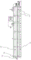
图1示出用于加热设备的第一区域的运输系统的侧视图,并且描述上压缩传送器带10、上压缩传送器带驱动链轮18和支撑下传送器链16的辊14;Figure 1 shows a side view of the transport system for the first zone of the heating plant and depicts the upper
图2示出用于加热设备的第一区域的张紧控制的侧视图,并且描述上压缩传送器带张紧器20和下传送器链张紧器22;Figure 2 shows a side view of the tension control for the first zone of the heating apparatus and depicts the upper compression
图3示出用于加热设备的第一区域的气流控制的侧视图,并且描述燃烧室和鼓风机30、热空气分配管道32、回流空气腔室34、气流36的回流空气重新循环方向、通风柜38、回流空气腔室和通风柜排气管40以及补偿空气进口42;Figure 3 shows a side view of airflow control for the first zone of the heating plant and depicts the combustion chamber and
图4示出用于加热设备的第一区域的气流控制的端视图,并且描述燃烧器和燃烧室组件50,气流方向表示为远离燃烧器的向下通风管道52、经过玻璃纤维介质54的向上通风的气流方向,以及从回流空气腔室到重新循环56的气流方向;FIG. 4 shows an end view of airflow control for the first zone of the heating apparatus and depicts the burner and
图5示出加热设备的第一区域的俯视图,并且描述用于放样控制的上压缩传送器带起重器60;Figure 5 shows a top view of the first area of the heating apparatus and depicts the upper compression
图6示出加热设备的第二区域的侧视图,并且描述燃烧室和鼓风机70,热空气供给分配管道72、回流空气腔室74、回流空气排气管76、补偿空气进口78以及玻璃纤维介质的行进方向79,竖直的虚线表示与第一区域的边界;Figure 6 shows a side view of the second area of the heating apparatus and depicts the combustion chamber and
图7示出上压缩传送器带辊链80和3英寸支撑轨道82的3英寸的俯视图;Figure 7 shows a 3 inch top view of the upper compression conveyor
图8示出上压缩传送器带横向支撑装置90的端视图;以及Figure 8 shows an end view of the upper compression conveyor belt lateral support 90; and
图9示出外置轴承100和绝缘板110的前视图。FIG. 9 shows a front view of the outboard bearing 100 and the
为了清楚和简洁,所有附图中,类似的元件和组件将带有相同的标识和标号。For the sake of clarity and brevity, similar elements and components will bear the same designations and reference numerals throughout the drawings.
具体实施方式Detailed ways
公开有一种用于固化玻璃纤维的加热设备,该玻璃纤维具有长度延伸的双重固化加热系统,其带有至少十五英尺的第一加热区域和至少十五英尺的第二加热区域。第一加热区域和第二加热区域每个的最大长度都不大于一百英尺。第一加热区域在三百华氏度(300°F)至五百华氏度(500°F)的温度范围内操作,第二加热区域在两百七十五华氏度(275°F)至五百华氏度(500°F)的温度操作。第二加热区域在低温范围端操作,该低温范围端比第一加热区域至少冷二十五华氏度(25°F)。A heating apparatus is disclosed for curing glass fibers having a dual-curing heating system extending in length with a first heating zone of at least fifteen feet and a second heating zone of at least fifteen feet. The maximum length of each of the first heating zone and the second heating zone is no greater than one hundred feet. The first heating zone operates in a temperature range of three hundred degrees Fahrenheit (300°F) to five hundred degrees Fahrenheit (500°F) and the second heating zone two hundred and seventy-five degrees Fahrenheit (275°F) to five hundred Temperature operation in degrees Fahrenheit (500°F). The second heating zone operates at the low temperature range end that is at least twenty-five degrees Fahrenheit (25°F) cooler than the first heating zone.
参考图1和2,成一体的张紧器机构(上压缩传送器带张紧器20、下传送器链张紧器22和上压缩传送器带驱动链轮18)控制对下传送器链16和带有支撑下传送器链16的辊14的上压缩传送器带10的张紧。第一加热区域具有上张紧的压缩系统,其具有用于玻璃纤维介质12的上压缩传送器带张紧器20和下传送器链张紧器22。第一加热区域接收在第一传送器带上被传送的玻璃纤维介质。上压缩传送器带10安装至横向支撑装置90(图8所示),横向支撑装置90安装成垂直于玻璃纤维介质12的行进方向,从而防止带越过玻璃纤维介质12的宽度向下偏斜。横向支撑装置90的每一端附接至带有搭乘在支撑轨道82中的辊14(图7所示)的上压缩传送器带辊链80(图7所示)。1 and 2, an integrated tensioner mechanism (upper compression
上压缩传送器带10由允许空气流动经过带的线网组成。上压缩传送器带10安装在支撑轨道82中,支撑轨道82能够通过同步的起重器60(图5所示)而上升和降低。第一加热区域和第二加热区域中的每一个中的玻璃纤维介质的表面附近的温度传感器被用来自动地控制每个燃烧器和燃烧室组件50(图4所示)中的气阀,以维持恒定的温度。图3描述温度传感器的位置44。闭环系统中的交变电流(AC)逆变器使上压缩传送器带10、后炉积聚器和后炉上绕组件的速度以及下传送器链16的速度同步,阻止玻璃纤维介质12的表面的摩擦,同时进一步控制对玻璃纤维介质12的张紧。The upper
每个加热区域具有燃烧室。存在用于第一加热区域的鼓风机30(图3所示)和用于第二加热区域的鼓风机70(图6所示),以及在每个加热区域的最上面部分的分离的排气管。第一加热区域也包含空气腔室和通风柜排气管40,第二加热区域包含回流空气排气管76。Each heating zone has a combustion chamber. There is a blower 30 (shown in Figure 3) for the first heating zone and a blower 70 (shown in Figure 6) for the second heating zone, and a separate exhaust duct at the uppermost portion of each heating zone. The first heating zone also contains the air plenum and
然后经过在第一加热区域的最上面部分的腔室34中的可调整的孔,加热空气在介质12上方被收集。那里,腔室34中的回流空气能够回流至燃烧室和鼓风机30,或者以再循环空气百分比能够经过补偿空气进口42被控制的方式,排出第一加热区域回流空气腔室和通风柜排气管40。The heated air is then collected over the medium 12 through adjustable holes in the
参考图5,经过自动地向上或者向下调整并移动上压缩传送器带10的起重器60,产品的放样被控制。该移动的该上压缩带改变放样为典型的3秒,但是当突然从1/4英寸放样改变至5英寸放样,其足够迅速以致没有介质12被损坏时,能够几乎瞬间到达或者高达最大值20秒。Referring to Figure 5, the lay-out of the product is controlled by automatically adjusting and moving the
本文也公开有一种带有多个加热区域的设备,该多个加热区域最少带有至少两个加热区。第一区域被加热到至少三百华氏度(300°F)至不多于五百华氏度(500°F)的温度范围。第一加热区域具有布置在第一区域的最上面部分的燃烧室和鼓风机30,其带有补偿空气进口42和回流空气腔室34,带有空气流动的回流空气重新循环方向(如图3所示)。此外,第一加热区域的最上面部分具有在上压缩传送器带张紧器20正上方、与通风柜排气管40和位于加热设备外部的通风柜38联接的回流空气腔室排气,上压缩传送器带张紧器20布置在下传送器链张紧器22上方。Also disclosed herein is an apparatus having a plurality of heating zones with a minimum of at least two heating zones. The first zone is heated to a temperature range of at least three hundred degrees Fahrenheit (300°F) to no more than five hundred degrees Fahrenheit (500°F). The first heating zone has a combustion chamber and
图4中,利用行进在向下通风管道52中的热空气的方向,表示了相对于燃烧室组件50的管道体系的气流和位置。利用热空气经过介质54向上通风的方向和从回流空气腔室到重新循环56的空气的流动,空气在炉子的最下面区域被输送。利用将加热空气从鼓风机和燃烧室经过布置成沿着第一区域的外壁的管道引导至第一区域的最下面部分的管道,管道体系连接到那儿。经过在下传送器链16下的一系列矩形槽,加热空气离开管道体系,下传送器链16经过下传送器链16利用向上流动呈送加热空气。然后加热空气经过玻璃纤维介质经过玻璃纤维介质的第一表面向上流动至玻璃纤维介质的第二表面,然后向上经过上压缩传送器带10。In FIG. 4 , the airflow and location of the ductwork relative to the
第一区域中经过炉子指定行进距离的第一上压缩传送器带10提供玻璃纤维介质与加热空气的连续接触,该指定行进距离至少十五英尺并且不多于一百英尺,空气加热到三百华氏度(300°F)以上至不高于五百华氏度(500°F)。保持温度必需的指定时间段,以允许放样开始形成为第二加热区域比用于玻璃纤维介质的最后固化的下端冷25度。加热设备作用为用于玻璃纤维的放样控制系统和固化设备,并且被设计带有两个延伸长度的区域:第一加热区域和第二加热区域。此设备允许使用带有最小量的添加剂(如,催化剂或者缓冲剂)的脲醛或者丙烯粘结剂,使生产被更好限定并且表皮更硬的质量玻璃纤维介质的处理的变数最小且简单化。添加DEG(二甘醇)作为添加剂调节水分;然而,其仅能够以小的重量百分比被添加。此外,此处理允许水分在更宽范围水平的未膨胀的纤维玻璃毡片成功固化。管道分配来自下传送器链下方的加热空气分配管道的加热空气。这保持了下传送器链清洁器并且阻止大部分颗粒进入排气流,保持了所有的排气管道过滤器。通过再循环第一加热区域中百分之八十的加热空气和第二加热区域中百分之九十五的加热空气,加热设备进一步节省能量,以最大化能量效率。The first upper
利用由编码器控制的分离的直接驱动,能够实现上压缩传送器带10和下传送器链16的同步。即使带随着时间的过去而拉长以及组件磨损,运用编码器以维持同步。利用在加热设备下游的积聚器和上绕机构,能够进一步维持同步。在处理的整个过程中,积聚器和上绕机构都维持对介质的适当张紧。上压缩传送器带10装入在附接至起重器60的框架中,从而能够在介质仍然被处理的同时非常迅速地改变玻璃纤维介质的放样。起重器60非常迅速地响应并且调节至预设的设定点。Synchronization of the upper
为了提供更好的维护和更长的使用寿命,在支撑下传送器链16的辊14的端部的设备辊外置轴承100已被重新安放至设备的外部,远离高热负载,从而在加热和固化设备处理玻璃纤维的同时能够润滑轴承。外置轴承100被装入在绝缘板110内,绝缘板110是在润滑发生的同时维持加热设备的温度的包壳。In order to provide better maintenance and longer service life, the equipment roller
减少的热暴露改进了外置轴承100的寿命并且延伸了所需要的润滑之间的间隔。用于上压缩传送器带10上的驱动链的润滑系统润滑两个驱动链的长度,在传送器带的每一侧具有一个使用于链润滑的停工时间最小化。进一步,访问面板被添加,以锁上沿着第一加热区域和第二加热区域的长度的所有位置,以便于组件维护和处理监测。The reduced heat exposure improves the life of the
由于对于本领域技术人员而言配合特定的操作需要和环境而变化以做出修改和改变是显然的,所以,所公开的主题并不考虑为局限于为了公开而选择的示例,并且涵盖不构成对此主题的真实精神和范围的偏离的所有改变和修改。The disclosed subject matter is not considered to be limited to the examples chosen for disclosure, and does not cover All changes and modifications that depart from the true spirit and scope of this subject matter.
Claims (19)
Applications Claiming Priority (3)
| Application Number | Priority Date | Filing Date | Title |
|---|---|---|---|
| US201562177926P | 2015-03-27 | 2015-03-27 | |
| US62/177,926 | 2015-03-27 | ||
| PCT/US2016/024341 WO2016160613A1 (en) | 2015-03-27 | 2016-03-25 | Skin stiffness characteristics and loft control production system and method with variable moisture content in input fiberglass |
Publications (2)
| Publication Number | Publication Date |
|---|---|
| CN107531423A CN107531423A (en) | 2018-01-02 |
| CN107531423B true CN107531423B (en) | 2020-07-10 |
Family
ID=56976570
Family Applications (1)
| Application Number | Title | Priority Date | Filing Date |
|---|---|---|---|
| CN201680018730.1A Expired - Fee Related CN107531423B (en) | 2015-03-27 | 2016-03-25 | Equipment for processing fiberglass media |
Country Status (4)
| Country | Link |
|---|---|
| US (3) | US9694510B2 (en) |
| EP (1) | EP3274279A4 (en) |
| CN (1) | CN107531423B (en) |
| WO (1) | WO2016160613A1 (en) |
Family Cites Families (97)
| Publication number | Priority date | Publication date | Assignee | Title |
|---|---|---|---|---|
| BE412804A (en) | 1935-11-18 | |||
| US2357676A (en) | 1941-10-04 | 1944-09-05 | Advance Solvents & Chemical Co | Plasticizers and tackifiers for rubber, waxes, and the like |
| US2460899A (en) | 1944-08-30 | 1949-02-08 | Johns Manville | Method of mat formation |
| US2486217A (en) | 1945-07-20 | 1949-10-25 | Johns Manville | Method and apparatus for expansion of fibrous mats |
| US2574221A (en) | 1946-03-16 | 1951-11-06 | Johns Manville | Method of forming a multilayered mat of intercrossed filaments |
| US2609320A (en) | 1947-05-29 | 1952-09-02 | Johns Manville | Method of making flexible unwoven fabric |
| US2639759A (en) | 1947-07-03 | 1953-05-26 | Owens Corning Fiberglass Corp | Method of forming glass fiber mats |
| US2546230A (en) | 1947-10-10 | 1951-03-27 | Johns Manville | Glass product and method of making the same |
| US2505045A (en) | 1948-07-27 | 1950-04-25 | Johns Manville | Filamentary product and method of its production |
| US2644780A (en) | 1949-01-11 | 1953-07-07 | Johns Manville | Method of forming fluffed filamentary masses and article produced thereby |
| US2798531A (en) | 1953-01-06 | 1957-07-09 | American Air Filter Co | Condensed filamentous mat and method and apparatus for making same |
| US2779969A (en) * | 1953-01-15 | 1957-02-05 | United Cork Companies | Apparatus for the continuous manufacture of compressed boards and sheets |
| US2913037A (en) | 1953-12-29 | 1959-11-17 | Johns Manville | Method and apparatus for forming condensed glass fiber mats |
| US2729582A (en) | 1954-04-08 | 1956-01-03 | Johns Manville | Method for making unwoven fabrics |
| US2751483A (en) | 1954-06-28 | 1956-06-19 | Lavoie Lab Inc | Constant temperature oven |
| US2997096A (en) | 1957-05-16 | 1961-08-22 | Owens Corning Fiberglass Corp | Multiple stage methods and apparatus for curing the binder of fibrous glass masses |
| US3096161A (en) | 1957-09-16 | 1963-07-02 | Owens Corning Fiberglass Corp | Heat setting of binder of fibrous masses |
| US2964439A (en) | 1957-12-26 | 1960-12-13 | Johns Manville | Method of forming a multi-layer mat of intercrossed filaments |
| US3051602A (en) | 1959-01-12 | 1962-08-28 | United States Gypsum Co | Multi-speed furnace traverse |
| US3097710A (en) | 1959-07-13 | 1963-07-16 | American Air Filter Co | Automatic glass loader |
| US3234041A (en) * | 1960-01-29 | 1966-02-08 | Owens Corning Fiberglass Corp | Method of applying binder to porous fibrous glass mats |
| US3134704A (en) | 1960-05-13 | 1964-05-26 | Reichhold Chemicals Inc | Method of and apparatus for multiple forming and winding of glass and resin filaments |
| NL122881C (en) | 1960-11-25 | |||
| US3322585A (en) | 1963-02-27 | 1967-05-30 | American Air Filter Co | Method of making a condensed filamentous mat |
| US3278282A (en) | 1963-10-11 | 1966-10-11 | Jaray Francis Ferdinand | Glass spinning crucible |
| US3459613A (en) | 1965-07-29 | 1969-08-05 | American Air Filter Co | Method and apparatus for making filamentous mat |
| US3476635A (en) | 1966-07-11 | 1969-11-04 | American Air Filter Co | Graduated density filamentous mat |
| US3526557A (en) | 1966-11-18 | 1970-09-01 | American Air Filter Co | Method for making filamentous mats |
| NL131842C (en) | 1967-04-04 | |||
| US3623857A (en) | 1968-03-22 | 1971-11-30 | Johns Manville | Glass melting pot |
| US3573016A (en) | 1968-07-24 | 1971-03-30 | Owens Corning Fiberglass Corp | Method and apparatus for forming fibers |
| CH552462A (en) * | 1971-07-14 | 1974-08-15 | Mets Nv Konstruktiewerkhuizen | CONTINUOUSLY WORKING PRESS FOR THE PRODUCTION OF PANELS LIKE CHIPBOARD OR FIBER PANELS. |
| US3826903A (en) | 1972-01-03 | 1974-07-30 | Owens Corning Fiberglass Corp | Method and apparatus for control of conditions in a process |
| US3837138A (en) | 1973-02-23 | 1974-09-24 | Johns Manville | Method and apparatus for compressing material and enclosing the same in a plastic film |
| DE2323519B2 (en) * | 1973-05-10 | 1976-04-22 | J.M. Voith Gmbh, 7920 Heidenheim | WEDGE PRESS FOR CONTINUOUS DEWATERING OF A FIBER WEB |
| US3937860A (en) | 1975-04-23 | 1976-02-10 | J. P. Stevens & Co., Inc. | Filtration material |
| US4188197A (en) | 1975-09-25 | 1980-02-12 | Dennison Manufacturing Company | Particulate filtering |
| DE2545624C3 (en) * | 1975-10-11 | 1978-07-27 | Kuesters, Eduard, 4150 Krefeld | Press for exerting a surface pressure |
| US4227906A (en) | 1976-07-09 | 1980-10-14 | Owens-Corning Fiberglas Corporation | Environmental control for mineral fiber-forming |
| JPS5314834A (en) | 1976-07-23 | 1978-02-09 | Nitto Boseki Co Ltd | Orifice plate in glass fiber spinning furnace |
| DK173779A (en) | 1978-05-08 | 1979-11-09 | Nitto Boseki Co Ltd | HOLE PLATES FOR A BUSHING FOR USE WHEN PULLING GLASS FIBERS |
| US4263007A (en) | 1978-06-05 | 1981-04-21 | Saint-Gobain Industries | Apparatus for heat treatment of fibrous mats |
| US4321074A (en) | 1978-10-16 | 1982-03-23 | Owens-Corning Fiberglas Corporation | Method and apparatus for manufacturing glass fibers |
| DE2922151A1 (en) * | 1979-05-31 | 1980-12-11 | Sandvik Conveyor Gmbh | DOUBLE BAND PRESS |
| US4363645A (en) | 1980-04-04 | 1982-12-14 | Owens-Corning Fiberglas Corporation | Annular bushing for forming glass fibers |
| DE3107589C2 (en) * | 1981-02-27 | 1986-01-30 | Bison-Werke Bähre & Greten GmbH & Co KG, 3257 Springe | Device for the continuous production of chipboard, fiberboard or similar boards |
| ATE22782T1 (en) | 1982-11-15 | 1986-11-15 | System Finanz Gmbh | CIGARETTES DISPENSER WITH ELECTRIC LIGHTER. |
| DE3248753A1 (en) * | 1982-12-31 | 1984-07-12 | Akzo Gmbh, 5600 Wuppertal | METHOD FOR COMPRESSING FIBER FABRICS |
| US4566154A (en) | 1983-08-02 | 1986-01-28 | Scott Paper Company | Nonwoven web spreader |
| CA1340751C (en) * | 1984-07-03 | 1999-09-21 | William T. Fletcher | Apparatus for producing reoriented glass fibre material |
| US4940502A (en) * | 1985-05-15 | 1990-07-10 | E. I. Du Pont De Nemours And Company | Relating to bonded non-woven polyester fiber structures |
| FR2587738B1 (en) | 1985-09-25 | 1988-02-19 | Saint Gobain Isover | REPAIR OF BONDING COMPOSITIONS FOR MINERAL FIBERS |
| US5532050A (en) * | 1986-06-30 | 1996-07-02 | Wm. T. Burnett & Co., Inc. | Densified thermo-bonded synthetic fiber batting |
| CN1009443B (en) * | 1986-11-14 | 1990-09-05 | 库特·赫尔德·法布里肯特 | Method and apparatus for manufacturing composite wood product board |
| US4734996A (en) * | 1986-12-15 | 1988-04-05 | Owens-Corning Fiberglas Corporation | Method and apparatus for heating mineral fibers |
| US5149394A (en) * | 1988-10-14 | 1992-09-22 | Kurt Held | Method and apparatus for continuously fabricating laminates |
| US5284546A (en) * | 1991-01-04 | 1994-02-08 | Tilby Sydney E | Apparatus for manufacture of structural panel |
| US5139841A (en) | 1991-03-27 | 1992-08-18 | James River Corporation Of Virginia | Superabsorbent towel with scrim reinforcement |
| DE4129190A1 (en) | 1991-09-03 | 1993-03-04 | Held Kurt | METHOD AND DEVICE FOR THE CONTINUOUS PRODUCTION OF RESIN IMPREGNATED MATERIALS |
| US5340651A (en) | 1991-10-16 | 1994-08-23 | Hollinee Corporation | Glass fiber evaporative cooler media, method of forming same, use thereof in an evaporative cooling method, and an evaporative cooler apparatus utilizing glass fiber cooling media |
| CA2106627A1 (en) | 1992-09-22 | 1994-03-23 | David W. Bainbridge | Glass fiber binding composition containing latex elastomer and method of reducing fallout from glass fiber compositions |
| DE4310685C2 (en) * | 1993-04-01 | 1995-01-26 | Held Kurt | Process for the continuous direct coating of chipboard and device for preparing the chipboard surface |
| US5458051A (en) * | 1993-11-29 | 1995-10-17 | G. S. Blodgett Corporation | Belt cooking apparatus |
| US5634954A (en) | 1994-03-30 | 1997-06-03 | Schuller International, Inc. | Fibrous filter media |
| US5832696A (en) * | 1994-09-21 | 1998-11-10 | Owens Corning Fiberglas Technology, Inc. | Method and apparatus for packaging compressible insulation material |
| DE4441017A1 (en) * | 1994-11-17 | 1996-05-23 | Dieffenbacher Gmbh Maschf | Process for continuous mfr. of sheets of wood esp. plywood or chipboard |
| US5695848A (en) | 1994-12-21 | 1997-12-09 | Nicofibers, Inc. | Panel formed from molded fiberglass strands |
| US5618622A (en) | 1995-06-30 | 1997-04-08 | Kimberly-Clark Corporation | Surface-modified fibrous material as a filtration medium |
| US5578371A (en) | 1995-08-25 | 1996-11-26 | Schuller International, Inc. | Phenol/formaldehyde fiberglass binder compositions exhibiting reduced emissions |
| US5672399A (en) | 1995-11-17 | 1997-09-30 | Donaldson Company, Inc. | Filter material construction and method |
| US6821614B1 (en) * | 1996-12-11 | 2004-11-23 | Boise Cascade Corporation | Apparatus and method for continuous formation of composites having filler and thermoactive materials, and products made by the method |
| CA2273961A1 (en) * | 1996-12-11 | 1998-06-18 | Boise Cascade Corporation | Apparatus and method for continuous formation of composites having filler and thermoactive materials, and products made by the method |
| US5846603A (en) | 1997-07-28 | 1998-12-08 | Superior Fibers, Inc. | Uniformly tacky filter media |
| US6605245B1 (en) * | 1997-12-11 | 2003-08-12 | Boise Cascade Corporation | Apparatus and method for continuous formation of composites having filler and thermoactive materials |
| US7090743B2 (en) * | 1999-09-20 | 2006-08-15 | Hunter Douglas Inc. | Pressure laminator apparatus |
| JP2003001028A (en) | 2001-06-22 | 2003-01-07 | Bridgestone Corp | Filter |
| EP1592690A1 (en) | 2003-02-14 | 2005-11-09 | Wyeth | Heterocyclyl-3-sulfonylazaindole or -azaindazole derivatives as 5-hydroxytryptamine-6 ligands |
| US20050006808A1 (en) | 2003-06-26 | 2005-01-13 | Thomas David W. | Method for inline production of smooth surface board |
| US6877246B1 (en) * | 2003-12-30 | 2005-04-12 | Kimberly-Clark Worldwide, Inc. | Through-air dryer assembly |
| US20060093815A1 (en) | 2004-11-04 | 2006-05-04 | Wilkins Rodney R | Glass fiber filtration media with at least two different fiber diameters |
| DE102005039709A1 (en) | 2005-08-23 | 2007-03-01 | Johns Manville International, Inc., Denver | Glass fiber nonwovens, resin mats and process for their preparation |
| US20080015301A1 (en) | 2006-07-17 | 2008-01-17 | Natalie Suzanne Grooms | Modified urea-formaldehyde resin composition, methods of making and articles made therefrom |
| US8129019B2 (en) | 2006-11-03 | 2012-03-06 | Behnam Pourdeyhimi | High surface area fiber and textiles made from the same |
| CN101868290A (en) | 2007-11-20 | 2010-10-20 | 克拉考公司 | Filter media, fine fibers below 100 nm and method |
| US8080488B2 (en) | 2008-03-10 | 2011-12-20 | H. B. Fuller Company | Wound glass filament webs that include formaldehyde-free binder compositions, and methods of making and appliances including the same |
| US20090266759A1 (en) | 2008-04-24 | 2009-10-29 | Clarcor Inc. | Integrated nanofiber filter media |
| EP2321029B1 (en) | 2008-07-18 | 2016-02-24 | Clarcor INC. | Multi-component filter media with nanofiber attachment |
| JP5875180B2 (en) | 2008-12-05 | 2016-03-02 | イー・アイ・デュポン・ドウ・ヌムール・アンド・カンパニーE.I.Du Pont De Nemours And Company | Improved filter media with nanoweb layers |
| US8057566B1 (en) | 2009-08-11 | 2011-11-15 | Aaf-Mcquay Inc. | Fiberglass product |
| EP3578528A1 (en) * | 2009-10-09 | 2019-12-11 | Owens Corning Intellectual Capital, LLC | Bio-based binders for insulation and non-woven mats |
| US20110210061A1 (en) | 2010-02-26 | 2011-09-01 | Clarcor Inc. | Compressed nanofiber composite media |
| US20120304603A1 (en) | 2010-12-08 | 2012-12-06 | E. I. Du Pont De Nemours And Company | Low elongation structures for hot gas filtration |
| US20120271445A1 (en) * | 2011-04-19 | 2012-10-25 | Owens Corning Intellectual Capital, Llc | Multivariable predictive control optimizer for glass fiber forming operation |
| EP2709749B1 (en) | 2011-05-17 | 2018-08-15 | Natrix Separations Inc. | Method of use of wrapped membranes for chromatography |
| FR2984371B1 (en) * | 2011-12-20 | 2014-01-10 | Saint Gobain Isover | STOVE FOR THE PRODUCTION OF A MINERAL WOOL PRODUCT |
| FR2994201B1 (en) * | 2012-07-31 | 2014-08-08 | Saint Gobain Isover | PROCESS FOR COOKING A CONTINUOUS MATTRESS OF MINERAL OR VEGETABLE FIBERS |
| US20140196423A1 (en) | 2013-01-11 | 2014-07-17 | American Air Filter Company Inc | Tactile Air Filter Media |
-
2016
- 2016-03-25 CN CN201680018730.1A patent/CN107531423B/en not_active Expired - Fee Related
- 2016-03-25 US US15/081,622 patent/US9694510B2/en active Active
- 2016-03-25 WO PCT/US2016/024341 patent/WO2016160613A1/en not_active Ceased
- 2016-03-25 EP EP16773868.1A patent/EP3274279A4/en not_active Withdrawn
-
2017
- 2017-06-30 US US15/640,302 patent/US10046477B2/en active Active
-
2018
- 2018-08-13 US US16/102,549 patent/US20190134845A1/en not_active Abandoned
Also Published As
| Publication number | Publication date |
|---|---|
| CN107531423A (en) | 2018-01-02 |
| US9694510B2 (en) | 2017-07-04 |
| US20190134845A1 (en) | 2019-05-09 |
| US20180043569A1 (en) | 2018-02-15 |
| US20160281283A1 (en) | 2016-09-29 |
| WO2016160613A1 (en) | 2016-10-06 |
| EP3274279A4 (en) | 2018-11-14 |
| EP3274279A1 (en) | 2018-01-31 |
| US10046477B2 (en) | 2018-08-14 |
Similar Documents
| Publication | Publication Date | Title |
|---|---|---|
| US10662105B2 (en) | Heating objects on a line-production oven | |
| US4263007A (en) | Apparatus for heat treatment of fibrous mats | |
| JPH0137678B2 (en) | ||
| KR20140105485A (en) | Oven for manufacturing a mineral wool product | |
| CN205152618U (en) | A layered drying and setting machine adopting roundabout track | |
| US9534844B2 (en) | Method for the continuous sintering of mineral material and sintering equipment | |
| CN87107272A (en) | Mineral Fiber Heating Methods | |
| FI121927B (en) | PROCEDURE AND BAND SINTERING SYSTEM FOR CONTINUOUS SINTERING OF PELLETERED MINERAL MATERIAL | |
| US4490927A (en) | Apparatus for curing fibrous mineral insulation material | |
| FI63071C (en) | ANORDNING FOER VAERMEHAERDNING AV FIBERMATTOR | |
| US4316865A (en) | Method for heat treatment of fibrous mats | |
| CN107531423B (en) | Equipment for processing fiberglass media | |
| US20130130185A1 (en) | Method for starting a sintering furnace, and sintering equipment | |
| FI126864B (en) | Glashärdningsugn | |
| HK1246259A1 (en) | Skin stiffness characteristics and loft control production system and method with variable moisture content in input fiberglass | |
| GB2235754A (en) | Web drying machine | |
| CN209408874U (en) | A kind of net belt type foamed ceramic production line | |
| CN1328562C (en) | Device for supporting conveyor belt in continuous control of material layer during sintering | |
| KR820002342B1 (en) | Method for heat treatment of fibrous mats | |
| US20050138834A1 (en) | Fiberglass insulation curing oven tower and method of curing fiberglass insulation |
Legal Events
| Date | Code | Title | Description |
|---|---|---|---|
| PB01 | Publication | ||
| PB01 | Publication | ||
| SE01 | Entry into force of request for substantive examination | ||
| SE01 | Entry into force of request for substantive examination | ||
| REG | Reference to a national code |
Ref country code: HK Ref legal event code: DE Ref document number: 1246259 Country of ref document: HK |
|
| TA01 | Transfer of patent application right |
Effective date of registration: 20200611 Address after: American West Virginia Applicant after: Advanced Fiber Co., Ltd Address before: American Texas Applicant before: Charles Douglas Spitler Applicant before: Rodney Ray Wilkins |
|
| TA01 | Transfer of patent application right | ||
| GR01 | Patent grant | ||
| GR01 | Patent grant | ||
| CF01 | Termination of patent right due to non-payment of annual fee |
Granted publication date: 20200710 Termination date: 20210325 |
|
| CF01 | Termination of patent right due to non-payment of annual fee | ||
| REG | Reference to a national code |
Ref country code: HK Ref legal event code: WD Ref document number: 1246259 Country of ref document: HK |