CN107407799B - Correction of aberrations in incoherent imaging systems using fourier stack imaging techniques - Google Patents
Correction of aberrations in incoherent imaging systems using fourier stack imaging techniques Download PDFInfo
- Publication number
- CN107407799B CN107407799B CN201680014898.5A CN201680014898A CN107407799B CN 107407799 B CN107407799 B CN 107407799B CN 201680014898 A CN201680014898 A CN 201680014898A CN 107407799 B CN107407799 B CN 107407799B
- Authority
- CN
- China
- Prior art keywords
- image
- fluorescence
- sample
- images
- aberration
- Prior art date
- Legal status (The legal status is an assumption and is not a legal conclusion. Google has not performed a legal analysis and makes no representation as to the accuracy of the status listed.)
- Active
Links
Images


Classifications
-
- G—PHYSICS
- G02—OPTICS
- G02B—OPTICAL ELEMENTS, SYSTEMS OR APPARATUS
- G02B21/00—Microscopes
- G02B21/0004—Microscopes specially adapted for specific applications
- G02B21/002—Scanning microscopes
- G02B21/0024—Confocal scanning microscopes (CSOMs) or confocal "macroscopes"; Accessories which are not restricted to use with CSOMs, e.g. sample holders
- G02B21/0052—Optical details of the image generation
- G02B21/0072—Optical details of the image generation details concerning resolution or correction, including general design of CSOM objectives
-
- G—PHYSICS
- G02—OPTICS
- G02B—OPTICAL ELEMENTS, SYSTEMS OR APPARATUS
- G02B21/00—Microscopes
- G02B21/0004—Microscopes specially adapted for specific applications
- G02B21/002—Scanning microscopes
- G02B21/0024—Confocal scanning microscopes (CSOMs) or confocal "macroscopes"; Accessories which are not restricted to use with CSOMs, e.g. sample holders
- G02B21/0032—Optical details of illumination, e.g. light-sources, pinholes, beam splitters, slits, fibers
-
- G—PHYSICS
- G02—OPTICS
- G02B—OPTICAL ELEMENTS, SYSTEMS OR APPARATUS
- G02B21/00—Microscopes
- G02B21/0004—Microscopes specially adapted for specific applications
- G02B21/002—Scanning microscopes
- G02B21/0024—Confocal scanning microscopes (CSOMs) or confocal "macroscopes"; Accessories which are not restricted to use with CSOMs, e.g. sample holders
- G02B21/0052—Optical details of the image generation
- G02B21/0056—Optical details of the image generation based on optical coherence, e.g. phase-contrast arrangements, interference arrangements
-
- G—PHYSICS
- G02—OPTICS
- G02B—OPTICAL ELEMENTS, SYSTEMS OR APPARATUS
- G02B21/00—Microscopes
- G02B21/0004—Microscopes specially adapted for specific applications
- G02B21/002—Scanning microscopes
- G02B21/0024—Confocal scanning microscopes (CSOMs) or confocal "macroscopes"; Accessories which are not restricted to use with CSOMs, e.g. sample holders
- G02B21/008—Details of detection or image processing, including general computer control
-
- G—PHYSICS
- G02—OPTICS
- G02B—OPTICAL ELEMENTS, SYSTEMS OR APPARATUS
- G02B27/00—Optical systems or apparatus not provided for by any of the groups G02B1/00 - G02B26/00, G02B30/00
- G02B27/0025—Optical systems or apparatus not provided for by any of the groups G02B1/00 - G02B26/00, G02B30/00 for optical correction, e.g. distorsion, aberration
-
- G—PHYSICS
- G02—OPTICS
- G02B—OPTICAL ELEMENTS, SYSTEMS OR APPARATUS
- G02B21/00—Microscopes
- G02B21/0004—Microscopes specially adapted for specific applications
- G02B21/002—Scanning microscopes
- G02B21/0024—Confocal scanning microscopes (CSOMs) or confocal "macroscopes"; Accessories which are not restricted to use with CSOMs, e.g. sample holders
- G02B21/0052—Optical details of the image generation
- G02B21/0076—Optical details of the image generation arrangements using fluorescence or luminescence
Landscapes
- Physics & Mathematics (AREA)
- General Physics & Mathematics (AREA)
- Optics & Photonics (AREA)
- Chemical & Material Sciences (AREA)
- Analytical Chemistry (AREA)
- Engineering & Computer Science (AREA)
- Computer Vision & Pattern Recognition (AREA)
- General Engineering & Computer Science (AREA)
- Investigating, Analyzing Materials By Fluorescence Or Luminescence (AREA)
- Microscoopes, Condenser (AREA)
- Investigating Or Analysing Materials By Optical Means (AREA)
Abstract
Description
相关申请的交叉引用CROSS-REFERENCE TO RELATED APPLICATIONS
本申请要求在2015年3月13日提交的且题为“Correcting for Aberrations inIncoherent Imaging System via Fourier Ptychographic Microscopy”的美国临时专利申请第62/133,130号的权益和优先权,其通过引用整体并入本文并用于所有目的。This application claims the benefit of and priority to US Provisional Patent Application No. 62/133,130, filed March 13, 2015, and entitled "Correcting for Aberrations in Incoherent Imaging System via Fourier Ptychographic Microscopy," which is incorporated herein by reference in its entirety and for all purposes.
领域field
本文描述的某些方面大体涉及成像方法和系统,更具体地,涉及用于使用傅立叶叠层成像技术在不相干成像系统中进行像差校正的方法。Certain aspects described herein relate generally to imaging methods and systems, and more particularly, to methods for aberration correction in incoherent imaging systems using Fourier stack imaging techniques.
背景background
一般来说,成像透镜在设计上是不完美的。各种形状和性质的多个透镜通常在成像透镜中错综复杂地组合以补偿与理想透镜的偏差,但是这会带来高制造成本价格以及相关联的透镜设计的复杂性的增加。市场上可售的大多数透镜都在靠近其视场中心的区域提供了良好分辨率的图像,但在远离中心的区域提供差的分辨率。因此,获得良好分辨率的样本图像需要光栅扫描样本并保持被扫描图像的中心区域同时丢弃远离中心的部分。In general, imaging lenses are imperfect in design. Multiple lenses of various shapes and properties are often intricately combined in an imaging lens to compensate for deviations from an ideal lens, but this comes with high manufacturing costs and associated increased complexity of lens design. Most lenses available on the market provide images with good resolution in regions near the center of their field of view, but poor resolution in regions far from the center. Therefore, obtaining a good-resolution sample image requires raster scanning the sample and maintaining the central area of the scanned image while discarding parts that are far from the center.
明视场成像为最流行的显微镜模态之一。明视场显微镜通常用白光照射样品并捕获透射光的图像。明视场图像相位衬度提供了有关样本结构的信息。结合相位衬度方法,可定量测量样本的吸收率、厚度和色散。生物学中另一个越来越重要的显微镜模态为荧光成像。荧光可以通过用荧光团进行适当的标记来帮助在分子水平处显现化学成分和结构。通过在荧光团的激发光处照射标记的样本并以荧光团的发射波长成像,生物学家可以容易地识别出表现出感兴趣的化学性质的标记区域。结合明视场和荧光图像允许人们相对于样品的底层结构定位荧光区域。Brightfield imaging is one of the most popular microscopy modalities. Brightfield microscopy typically illuminates a sample with white light and captures an image of the transmitted light. Brightfield image phase contrast provides information about sample structure. Combined with the phase contrast method, the absorbance, thickness and dispersion of the sample can be quantitatively measured. Another microscopy modality of increasing importance in biology is fluorescence imaging. Fluorescence can help visualize chemical composition and structure at the molecular level by appropriate labeling with fluorophores. By illuminating the labeled sample at the excitation light of the fluorophore and imaging at the emission wavelength of the fluorophore, biologists can easily identify labeled regions that exhibit chemical properties of interest. Combining brightfield and fluorescence images allows one to locate fluorescent regions relative to the underlying structure of the sample.
概述Overview
某些方面涉及用于使用傅里叶叠层成像技术在不相干成像系统中进行像差校正的方法(ACIS方法)和实现这些方法的不相干成像系统(ACIS系统)。Certain aspects relate to methods for aberration correction in incoherent imaging systems using Fourier stack imaging techniques (ACIS methods) and incoherent imaging systems (ACIS systems) implementing these methods.
某些方面涉及像差校正的不相干成像方法,其包括在连续从不同角度提供入射到样品的相干平面波照明的同时采集样品的相干图像序列,其中,在从角度之一向样品提供相干平面波照明的同时采集相干图像中的每一个。该方法还包括基于从样品发出的不相干光来采集样品的不相干图像。该方法还包括实现嵌入式光瞳函数恢复过程以使用所采集的图像序列来构建改进分辨率的图像并估计成像系统的光瞳函数。该方法还包括基于所估计的光瞳函数来确定成像系统的光学传递函数,并使用去卷积过程从采集的不相干图像中去除像差以生成像差校正的不相干图像。在该方法中,去卷积过程使用成像系统的光学函数,该成像系统的光学函数根据使用所采集的图像序列估计的光瞳函数确定。Certain aspects relate to an aberration-corrected incoherent imaging method comprising acquiring a sequence of coherent images of a sample while continuously providing coherent plane wave illumination incident on the sample from different angles, wherein the coherent plane wave illumination is provided to the sample from one of the angles. Each of the coherent images is acquired simultaneously. The method also includes acquiring an incoherent image of the sample based on the incoherent light emitted from the sample. The method also includes implementing an embedded pupil function recovery process to use the acquired image sequence to construct an image of improved resolution and to estimate a pupil function of the imaging system. The method also includes determining an optical transfer function of the imaging system based on the estimated pupil function, and using a deconvolution process to remove aberrations from the acquired incoherent images to generate an aberration-corrected incoherent image. In this method, the deconvolution process uses the optical function of the imaging system determined from the pupil function estimated using the acquired image sequence.
某些方面涉及包括可变相干光源的成像系统,该可变相干光源被配置成使用来自不同倾斜角度的相干平面波照明连续照射样本。该系统还包括被配置成向样品提供波长的第一波段的激发光源,该波长的第一波段被配置成激活样品中的荧光团以发射第一组荧光发射的光。该系统也包括光学系统和一个或更多个图像传感器。该光学系统具有用于收集从样品发出的光的收集光学器件,其中该光学系统包括发射滤光片,在激发光源向样品提供波长的第一波段时,该发射滤光片用于使第一组荧光发射通过而阻挡其他波长,光学系统被配置成将光传播到一个或更多个图像传感器。一个或更多个图像传感器被配置成在可变相干光源利用相干平面波照明以不同倾斜角度连续照射样品的同时采集样品的相干图像序列,该一个或更多个图像传感器还被配置成基于不相干照明来采集样品的不相干图像。该系统还包括与一个或更多个图像传感器电气通信的一个或更多个处理器,以接收相干图像的序列和不相干图像的图像数据。一个或更多个处理器也被配置成实现存储在存储器中的指令以利用嵌入式光瞳函数恢复过程来构建改进的分辨率的图像,并且通过利用所采集的相干图像序列的图像数据使用嵌入式光瞳函数恢复过程来估计成像系统的光瞳函数。一个或更多个处理器还被配置成实现存储在存储器中的指令,以基于所估计的光瞳函数来确定成像系统的光学传递函数。一个或更多个处理器还被配置成实现存储在存储器中的指令以通过使用去卷积过程从所采集的不相干图像中去除像差来生成像差校正的不相干图像,其中该去卷积过程使用成像系统的光学函数,该成像系统的光学函数根据使用所采集的图像序列所估计的光瞳函数来确定。Certain aspects relate to an imaging system including a variable coherent light source configured to continuously illuminate a sample using coherent plane wave illumination from different tilt angles. The system also includes an excitation light source configured to provide the sample with a first range of wavelengths configured to activate fluorophores in the sample to emit light of the first set of fluorescent emissions. The system also includes an optical system and one or more image sensors. The optical system has collection optics for collecting light emanating from the sample, wherein the optical system includes an emission filter for causing the first wavelength to be provided by the excitation light source to the sample The set of fluorescent emission is passed through while other wavelengths are blocked, and the optical system is configured to propagate the light to one or more image sensors. One or more image sensors are configured to acquire a sequence of coherent images of the sample while the variable coherent light source continuously illuminates the sample at different tilt angles using coherent plane wave illumination, the one or more image sensors are further configured to be based on incoherence Illumination to acquire incoherent images of the sample. The system also includes one or more processors in electrical communication with the one or more image sensors to receive the sequence of coherent images and image data of the incoherent images. The one or more processors are also configured to implement instructions stored in the memory to utilize the embedded pupil function recovery process to construct an improved resolution image, and to utilize the embedded image data by utilizing the acquired image data of the coherent image sequence The pupil function recovery process of the formula is used to estimate the pupil function of the imaging system. The one or more processors are also configured to implement instructions stored in the memory to determine an optical transfer function of the imaging system based on the estimated pupil function. The one or more processors are further configured to implement instructions stored in the memory to generate an aberration-corrected incoherent image by removing aberration from the acquired incoherent image using a deconvolution process, wherein the deconvolution The product process uses the optical function of the imaging system determined from the pupil function estimated using the acquired image sequence.
本申请还涉及以下内容:This application also addresses the following:
1)一种由成像系统实现的像差校正的不相干成像方法,包括:1) An aberration-corrected incoherent imaging method implemented by an imaging system, comprising:
(a)在连续从不同角度提供入射到样品的相干平面波照明的同时采集所述样品的相干图像的序列,其中,在从所述角度之一向所述样品提供相干平面波照明的同时采集所述相干图像的每一个;(a) a sequence of acquiring coherent images of the sample while successively providing coherent plane wave illumination incident to the sample from different angles, wherein the coherent images are acquired while providing coherent plane wave illumination to the sample from one of the angles each of the images;
(b)基于从所述样品发出的不相干光来采集所述样品的不相干图像;(b) acquiring an incoherent image of the sample based on the incoherent light emitted from the sample;
(c)实现嵌入式光瞳函数恢复过程以使用所采集的相干图像的序列来构建改进的分辨率图像并估计所述成像系统的光瞳函数;(c) implementing an embedded pupil function recovery process to use the acquired sequence of coherent images to construct improved resolution images and estimate the pupil function of the imaging system;
(d)基于所估计的光瞳函数确定所述成像系统的光学传递函数;以及(d) determining an optical transfer function of the imaging system based on the estimated pupil function; and
(e)使用去卷积过程从所采集的不相干图像中去除像差以生成像差校正的不相干图像,其中,所述去卷积过程使用所述成像系统的光学传递函数,所述成像系统的光学传递函数根据使用所采集的相干图像的序列所估计的所述光瞳函数确定。(e) using a deconvolution process to remove aberrations from the acquired incoherent images to generate aberration-corrected incoherent images, wherein the deconvolution process uses the optical transfer function of the imaging system, the imaging The optical transfer function of the system is determined from the pupil function estimated using the sequence of acquired coherent images.
2)根据1)所述的像差校正的不相干成像方法,其中:2) The incoherent imaging method for aberration correction according to 1), wherein:
来自所述样品的所述不相干光为荧光发射;以及the incoherent light from the sample is fluorescent emission; and
所述不相干图像为单色荧光图像。The incoherent images are monochromatic fluorescence images.
3)根据2)所述的像差校正的不相干成像方法,还包括将所述单色荧光图像转换为彩色荧光图像。3) The aberration-corrected incoherent imaging method according to 2), further comprising converting the monochromatic fluorescence image into a color fluorescence image.
4)根据1)所述的像差校正的不相干成像方法,还包括:4) The incoherent imaging method for aberration correction according to 1), further comprising:
将所采集的相干图像的视场划分成多个图块区域;dividing the field of view of the acquired coherent image into a plurality of tile regions;
为每个图块区域生成图块图像的序列;Generate a sequence of tile images for each tile region;
为每个图块区域生成不相干图块图像;以及generating an incoherent tile image for each tile region; and
对于每个图块区域,实现嵌入式光瞳函数恢复过程以使用所生成的图块图像的序列来构建改进的分辨率图块图像,并估计图块光瞳函数。For each tile region, an embedded pupil function recovery process is implemented to use the sequence of generated tile images to construct an improved resolution tile image, and to estimate the tile pupil function.
5)根据4)所述的像差校正的不相干成像方法,其中,针对每个图块区域并行构建所述改进的分辨率图块图像,并且并行估计对于每个图块区域的所述图块光瞳函数。5) The aberration-corrected incoherent imaging method according to 4), wherein the improved resolution tile images are constructed in parallel for each tile region, and the map for each tile region is estimated in parallel Block pupil function.
6)根据4)所述的像差校正的不相干成像方法,还包括:6) The incoherent imaging method for aberration correction according to 4), further comprising:
针对每个图块区域,基于所估计的图块光瞳函数确定图块光学传递函数;For each tile region, determine the tile optical transfer function based on the estimated tile pupil function;
针对每个图块区域,使用去卷积过程和利用所确定的图块光学传递函数从所述不相干图块图像中去除像差以生成像差校正的不相干图块图像;以及for each tile region, using a deconvolution process and utilizing the determined tile optical transfer function to remove aberrations from the incoherent tile image to generate an aberration corrected incoherent tile image; and
通过针对所述多个图块区域组合所述像差校正的不相干图块图像来生成所述像差校正的不相干图像。The aberration-corrected incoherent image is generated by combining the aberration-corrected incoherent tile images for the plurality of tile regions.
7)根据1)或5)所述的像差校正的不相干成像方法,其中,所述改进的分辨率图像的构建和所述光瞳函数的估计同时发生。7) The aberration-corrected incoherent imaging method according to 1) or 5), wherein the construction of the improved resolution image and the estimation of the pupil function occur simultaneously.
8)根据1)所述的像差校正的不相干成像方法,其中,实现嵌入式光瞳函数恢复过程以使用所采集的相干图像的序列来构建所述改进的分辨率图像包括恢复所述改进的分辨率图像的幅度和相位数据。8) The aberration-corrected incoherent imaging method of 1), wherein implementing an embedded pupil function recovery process to construct the improved resolution image using the acquired sequence of coherent images comprises restoring the improved Amplitude and phase data of the resolution images.
9)根据1)所述的像差校正的不相干成像方法,其中,所述角度是与所述成像系统的具有被成像的样品的表面的倾斜角度。9) The aberration-corrected incoherent imaging method according to 1), wherein the angle is an inclination angle to the surface of the imaging system having the imaged sample.
10)根据1)所述的像差校正的不相干成像方法,还包括:10) The incoherent imaging method for aberration correction according to 1), further comprising:
采集所述样品的至少一个附加的不相干图像;以及acquiring at least one additional incoherent image of the sample; and
对每个附加的不相干图像执行(c)、(d)和(e)以生成像差校正的不相干图像。(c), (d), and (e) are performed on each additional incoherent image to generate an aberration-corrected incoherent image.
11)根据10)所述的像差校正的不相干成像方法,其中,每个像差校正的不相干图像为单色的,所述方法还包括:11) The aberration-corrected incoherent imaging method according to 10), wherein each aberration-corrected incoherent image is monochromatic, and the method further comprises:
将每个单色荧光图像转换成彩色荧光图像;以及converting each monochromatic fluorescence image to a color fluorescence image; and
重叠彩色的像差校正的荧光图像以生成所述样品的多色荧光图像。The colored aberration-corrected fluorescence images are overlaid to generate a polychromatic fluorescence image of the sample.
12)根据1)所述的像差校正的不相干成像方法,其中,(b)发生在(a)之前。12) The aberration-corrected incoherent imaging method according to 1), wherein (b) occurs before (a).
13)根据1)所述的像差校正的不相干成像方法,其中,(b)发生在(c)之后或(d)之后。13) The aberration-corrected incoherent imaging method according to 1), wherein (b) occurs after (c) or after (d).
14)根据1)所述的像差校正的不相干成像方法,14) The incoherent imaging method for aberration correction according to 1),
还包括用被配置成激活提供第一组荧光发射的荧光团的波长的第一波段的激发光来照射所述样品,further comprising illuminating the sample with excitation light configured to activate a first wavelength band of wavelengths that provide a first set of fluorescent emission fluorophores,
还包括在用所述波长的第一波段的激发光照射所述样品的同时,在光路中引入发射滤光片,以及further comprising introducing an emission filter into the optical path while illuminating the sample with the excitation light of the first wavelength band, and
其中,所采集的不相干图像是基于所述第一组荧光发射的所述样品的荧光图像。Wherein the acquired incoherent images are fluorescence images of the sample based on the first set of fluorescence emission.
15)一种成像系统,包括:15) An imaging system comprising:
可变相干光源,所述可变相干光源被配置成使用来自不同倾斜角度的相干平面波照明连续照射样品;a variable coherent light source configured to continuously illuminate the sample using coherent plane wave illumination from different tilt angles;
激发光源,所述激发光源被配置成向所述样品提供波长的第一波段,所述波长的第一波段被配置成激活所述样品中的荧光团以发射第一组荧光发射的光;an excitation light source configured to provide the sample with a first range of wavelengths configured to activate fluorophores in the sample to emit light of a first set of fluorescent emissions;
光学系统,所述光学系统具有用于收集从所述样品发出的光的收集光学器件,其中,所述光学系统包括发射滤光片,在所述激发光源向所述样品提供波长的第一波段时,所述发射滤光片用于让所述第一组荧光发射通过而阻挡其他波长,所述光学系统被配置成将光传播到一个或更多个图像传感器;an optical system having collection optics for collecting light emitted from the sample, wherein the optical system includes an emission filter, the excitation light source provides the sample with a first band of wavelengths , the emission filter is configured to pass the first set of fluorescent emissions while blocking other wavelengths, and the optical system is configured to propagate the light to one or more image sensors;
所述一个或更多个图像传感器,所述一个或更多个图像传感器被配置成在所述可变相干光源使用来自不同的倾斜角度的相干平面波照明连续照射所述样品的同时采集所述样品的相干图像的序列,所述一个或更多个图像传感器还被配置成基于不相干照明来采集所述样品的不相干图像;以及the one or more image sensors configured to acquire the sample while the variable coherent light source continuously illuminates the sample using coherent plane wave illumination from different tilt angles a sequence of coherent images, the one or more image sensors further configured to acquire incoherent images of the sample based on incoherent illumination; and
一个或更多个处理器,所述一个或更多个处理器与所述一个或更多个图像传感器电气通信以接收所述相干图像的序列和所述不相干图像的图像数据,所述一个或更多个处理器还被配置成实现存储在存储器中的指令以:one or more processors in electrical communication with the one or more image sensors to receive the sequence of coherent images and image data of the incoherent images, the one The processor or processors are further configured to implement the instructions stored in the memory to:
利用嵌入式光瞳函数恢复过程,通过利用所采集的相干图像的序列的图像数据使用嵌入式光瞳函数恢复过程来构建改进的分辨率图像,并且同时估计所述成像系统的光瞳函数;using an embedded pupil function recovery process to construct an improved resolution image by utilizing the image data of the acquired sequence of coherent images using the embedded pupil function recovery process and simultaneously estimating a pupil function of the imaging system;
基于所估计的光瞳函数确定所述成像系统的光学传递函数;以及determining an optical transfer function of the imaging system based on the estimated pupil function; and
通过使用去卷积过程从所采集的不相干图像中去除像差来生成像差校正的不相干图像,其中,所述去卷积过程使用所述成像系统的光学传递函数,所述成像系统的光学传递函数根据使用所采集的相干图像的序列所估计的光瞳函数来确定。An aberration-corrected incoherent image is generated by removing aberrations from the acquired incoherent image using a deconvolution process that uses the optical transfer function of the imaging system, the imaging system's optical transfer function. The optical transfer function is determined from the pupil function estimated using the sequence of acquired coherent images.
16)根据15)所述的成像系统,其中,所述激发光源被指向为远离所述光学系统的所述收集光学器件。16) The imaging system of 15), wherein the excitation light source is directed away from the collection optics of the optical system.
17)根据15)所述的成像系统,其中,所述可变相干光源是离散光元件的圆形阵列或离散光元件的矩形阵列。17) The imaging system of 15), wherein the variable coherent light source is a circular array of discrete light elements or a rectangular array of discrete light elements.
18)根据15)所述的成像系统,其中,所述可变相干光源是LED阵列。18) The imaging system of 15), wherein the variable coherent light source is an LED array.
以下参考相关联的附图更详细地描述这些和其他特征。These and other features are described in greater detail below with reference to the associated drawings.
附图简述Brief Description of Drawings
图1为根据一些实施方案的能够实现ACIS成像方法的ACIS成像系统的框图。1 is a block diagram of an ACIS imaging system capable of implementing an ACIS imaging method, according to some embodiments.
图2为根据实施例的被配置成实现用于关节FP荧光成像的ACIS方法的ACIS成像系统的示例的示意图。2 is a schematic diagram of an example of an ACIS imaging system configured to implement an ACIS method for joint FP fluoroscopic imaging, according to an embodiment.
图3示出了描绘根据实施方案可以由ACIS成像系统实现的示例性ACIS成像方法的单次成像运行的操作的流程图。3 shows a flowchart depicting the operation of a single imaging run of an exemplary ACIS imaging method that may be implemented by an ACIS imaging system according to an embodiment.
图4示出了根据实施方案的描绘示例性EPRY过程的操作的流程图。4 shows a flowchart depicting the operation of an exemplary EPRY process, according to an embodiment.
图5包括根据实施方案被示为公式的一组图像,其示意性地表示从畸变不相干图像中去卷积OTF的操作。Figure 5 includes a set of images, shown as equations, schematically representing the operation of deconvolving an OTF from a distorted incoherent image, according to an embodiment.
图6A为根据实施方案在执行ACIS成像方法期间的实验结果的流程的示意表示。6A is a schematic representation of a flow of experimental results during execution of an ACIS imaging method, according to an embodiment.
图6B为根据一个方面的强度vs位置的曲线图。6B is a graph of intensity vs. position according to one aspect.
图6C包括根据实施方案的两个图像,左图像为高分辨率明视场图像和卷积之前的原始荧光图像的重叠图像,以及右图像为高分辨率明视场图像和去卷积后的像差校正荧光图像的重叠图像。Figure 6C includes two images, the left image is an overlay of the high resolution brightfield image and the original fluorescence image before convolution, and the right image is the high resolution brightfield image and the deconvoluted Overlaid images of aberration-corrected fluorescence images.
图7A包括根据实施方案从光轴偏移的特定样本ROI的原始图像和恢复的PSF。Figure 7A includes the original image and recovered PSF of a particular sample ROI shifted from the optical axis according to an embodiment.
图7B为根据实施方案的去卷积所得图像。7B is a deconvoluted resulting image, according to an embodiment.
图7C为根据实施方案利用以光轴为中心的相同的样本ROI捕获的原始图像。7C is a raw image captured with the same sample ROI centered on the optical axis, according to an embodiment.
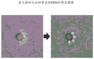
图8示出了根据实施方案使用具有修改的4f设置的ACIS成像系统执行ACIS方法所产生的大图像FOV的不同区域处遍及整个图像FOV的高分辨率傅里叶叠层成像(FP)图像和像差校正的荧光图像。8 shows high resolution Fourier tomography (FP) images throughout the entire image FOV at different regions of the large image FOV resulting from performing the ACIS method using an ACIS imaging system with a modified 4f setting according to an embodiment and Aberration-corrected fluorescence images.
详细描述Detailed Description
下面将参考附图描述本公开的实施例。Embodiments of the present disclosure will be described below with reference to the accompanying drawings.
I.介绍I. Introduction
最近,开发了结合傅里叶叠层成像(FP)技术的嵌入式光瞳函数恢复(EPRY)方法。标准EPRY方法表征透镜的空间变化像差,并且针对相干成像设置通过计算校正所捕获的图像。该标准EPRY方法的细节可以在G.Zheng、R.Horstmeyer和C.Yang于2013年在NaturePhotonics上发表的“Wide-field,high-resolution Fourier ptychographicmicroscopy”和X.Ou、G.Zheng和C.Yang于2014年在Optics Express上发表的“Embeddedpupil function recovery for Fourier ptychographic microscopy”中找到,其全部内容通过引用并入本文。该EPRY方法的细节也可以在2014年12月16日提交的且题为“EMBEDDED PUPIL FUNCTION RECOVERY FOR FOURIER PTYCHOGRAPHIC IMAGING DEVICES”的美国专利申请第14/572,493号中找到,其全部内容通过引用并入本文。此傅立叶叠层成像(FP)技术的细节可以在2013年10月28日提交的题为“FOURIER PTYCHOGRAPHIC IMAGINGSYSTEMS,DEVICES,AND METHODS”的美国专利申请14/065,280和在2014年8月22日提交的题为“VARIABLE-ILLUMINATION FOURIER PTYCHOGRAPHIC IMAGING DEVICES,SYSTEMS,ANDMETHODS”的美国专利申请14/466,481中找到,其全部内容通过引用并入本文。Recently, an embedded pupil function recovery (EPRY) method was developed that combines Fourier stack imaging (FP) techniques. Standard EPRY methods characterize the spatially varying aberrations of the lens and computationally correct the captured image for a coherent imaging setup. Details of this standard EPRY method can be found in "Wide-field, high-resolution Fourier ptychographicmicroscopy" by G. Zheng, R. Horstmeyer and C. Yang in NaturePhotonics 2013 and X. Ou, G. Zheng and C. Yang Found in "Embeddedpupil function recovery for Fourier ptychographic microscopy" published in Optics Express in 2014, which is incorporated herein by reference in its entirety. Details of this EPRY method can also be found in US Patent Application Serial No. 14/572,493, filed December 16, 2014, and entitled "EMBEDDED PUPIL FUNCTION RECOVERY FOR FOURIER PTYCHOGRAPHIC IMAGING DEVICES," the entire contents of which are incorporated herein by reference . Details of this Fourier tomography (FP) technique can be found in US Patent Application 14/065,280, filed October 28, 2013, and entitled "FOURIER PTYCHOGRAPHIC IMAGING SYSTEMS, DEVICES, AND METHODS" and filed on August 22, 2014 Found in US Patent Application 14/466,481 entitled "VARIABLE-ILLUMINATION FOURIER PTYCHOGRAPHIC IMAGING DEVICES, SYSTEMS, AND METHODS," the entire contents of which are incorporated herein by reference.
然而,使用不相干光实现了一些成像模态。例如,生物学家通常使用的荧光成像基于来自样本的不相干发射。标准EPRY方法不能直接用于校正捕获的荧光图像中的空间变化像差,因为标准EPRY方法被设计成主要用于相干成像系统。本文描述的ASIC方法可以校正捕获的荧光图像和其他不相干图像中的空间变化的像差。However, some imaging modalities are achieved using incoherent light. For example, fluorescence imaging commonly used by biologists is based on incoherent emission from a sample. Standard EPRY methods cannot be used directly to correct for spatially varying aberrations in captured fluorescence images because standard EPRY methods are designed primarily for use in coherent imaging systems. The ASIC method described here can correct for spatially varying aberrations in captured fluorescence images and other incoherent images.
根据某些方面,ASIC方法包括使用根据结合FP技术的标准EPRY方法所确定的光瞳函数来校正不相干成像系统中的像差的操作。首先,ACIS方法在可变相干照明源(例如,发光二极管(LED)阵列))提供来自多个照明角度的连续照明的同时捕获样本的明视场相干图像序列,在某些实施方案中,这些照明角度通常为倾斜角度。ACIS方法还采集样本视场的一个或更多个不相干图像。例如,当样本中的荧光团被激发光源激活时,可以成像荧光发射(信号)。利用所采集的明视场相干图像序列,ACIS方法使用结合FP技术的标准EPRY方法来表征相干成像系统的空间变化像差(通常称为“光瞳函数”)。ACIS方法将相干成像系统的光瞳函数转换为不相干光学传递函数,该不相干光学传递函数可以从荧光图像中去卷积以在整个成像系统的视场中实现良好分辨的像差校正的荧光图像。According to certain aspects, the ASIC method includes operations to correct for aberrations in an incoherent imaging system using a pupil function determined according to a standard EPRY method incorporating FP techniques. First, the ACIS method captures a sequence of bright-field coherent images of a sample while a variable coherent illumination source (eg, a light-emitting diode (LED) array) provides continuous illumination from multiple illumination angles, in certain embodiments, these The illumination angle is usually an oblique angle. The ACIS method also acquires one or more incoherent images of the sample field of view. For example, fluorescence emission (signal) can be imaged when a fluorophore in a sample is activated by an excitation light source. Using a sequence of acquired brightfield coherent images, the ACIS method uses standard EPRY methods combined with FP techniques to characterize the spatially varying aberrations (often referred to as "pupil function") of coherent imaging systems. The ACIS method converts the pupil function of a coherent imaging system into an incoherent optical transfer function that can be deconvolved from the fluorescence image to achieve well-resolved aberration-corrected fluorescence across the field of view of the imaging system image.
为了表征成像系统的空间变化像差,ACIS方法使用FP技术以通过使用相位恢复方法来重建样本视场的复振幅和相位函数,以将在不同角度的连续照明下捕获的一系列原始明视场图像拼接在一起。图2中示出了被配置成在以不同照明角度连续从LED阵列的一个或更多个LED的不同组中提供相干照明的同时捕获样本的一组明视场相干图像的成像系统的示例。To characterize the spatially varying aberrations of the imaging system, the ACIS method uses FP techniques to reconstruct the complex amplitude and phase functions of the sample field of view by using phase recovery methods to convert a series of original bright fields captured under continuous illumination at different angles Images are stitched together. An example of an imaging system configured to capture a set of bright field coherent images of a sample while continuously providing coherent illumination at different illumination angles from different groups of one or more LEDs of an LED array is shown in FIG. 2 .
如所述,ACIS方法在FP技术(FP-EPRY重建)内实现EPRY方法,其不仅能够恢复复合样本函数(幅度和相位),而且可以确定相干成像系统的光瞳函数。所确定的光瞳函数是包括成像系统的像差的相干成像系统的相干传递函数。因为对于所捕获图像上的不同区域的像差函数可以是不同的,所以在某些实施方案中,在FP-EPRY重建之前将样本的全视场图像平铺到较小区域中,使得像差在每个图块内大致相同。对于获得成像系统的不相干光学传递函数(OTF)的ACIS方法,所确定的光瞳函数与其自身在频域中卷积或在空间域中进行幅度平方。ACIS方法通过用来自激发光源(例如,激发LED)的激发光照射样本中的荧光团来获得不相干图像。以与上述相同的方式对图像进行平铺,并且通过去卷积过程(例如,维纳滤波器)在频域中对每个图块进行去卷积以去除如图3所示的像差。As mentioned, the ACIS method implements the EPRY method within the FP technique (FP-EPRY reconstruction), which can not only recover the composite sample function (magnitude and phase), but also determine the pupil function of the coherent imaging system. The determined pupil function is the coherent transfer function of the coherent imaging system including the aberrations of the imaging system. Because the disparity function can be different for different regions on the captured image, in some embodiments, the full field image of the sample is tiled into smaller regions prior to FP-EPRY reconstruction such that the disparity Roughly the same within each tile. For the ACIS method of obtaining the incoherent optical transfer function (OTF) of the imaging system, the determined pupil function is convolved with itself in the frequency domain or amplitude squared in the spatial domain. The ACIS method obtains incoherent images by illuminating fluorophores in a sample with excitation light from an excitation light source (eg, excitation LEDs). The image is tiled in the same manner as above, and each tile is deconvolved in the frequency domain by a deconvolution process (eg, Wiener filter) to remove aberrations as shown in Figure 3.
在某些实施方案中,ASIC方法可以在宽的成像系统视场(FOV)下生成高分辨率、相干明视场图像和/或像差校正的荧光图像。ASIC方法可以使用傅里叶叠层成像(FP)技术来提高明视场图像分辨率,该傅立叶叠层成像技术为最近开发的计算技术,其处理在角度变化照明下采集的图像序列。傅立叶叠层成像(FP)技术的细节在G.Zheng、R.Horstmeyer和C.Yang于2013年在Nat.Photonics 7(9)第739-745页发表的“Wide-field,high-resolution Fourier ptychographic microscopy”中进行讨论,其全部内容通过引用并入本文。在相位恢复过程中,FP技术恢复样本视场的相位信息,并且可以使用EPRY方法另外估计成像系统的像差。相位恢复过程的一些细节可以在X.Ou、R.Horstmeyer、C.Yang和G.Zheng于2013年在Opt.Lett.38(22)第4845-4848页发表的“Quantitative phaseimaging via Fourier ptychographic microscopy”中找到,其全部内容通过引用并入本文。标准EPRY过程的细节可以在X.Ou、G.Zheng、C.Yang于2014年在Opt.Express 22(5)第4960-4972页发表的“Embedded pupil function recovery for Fourier ptychographicmicroscopy”中找到,其全部内容通过引用并入本文。ASCI方法也可以使用相同的系统捕获荧光图像,并使用在FP-EPRY过程期间所估计的像差图来校正其像差。具体地,FP过程以空间变化的光瞳函数的形式输出复像差图,ASIC方法利用其计算成像系统的空间变化不相干点扩散函数(PSF),以在用于像差去除的荧光图像去卷积中使用。In certain embodiments, the ASIC method can generate high-resolution, coherent bright-field images and/or aberration-corrected fluorescence images over a wide field of view (FOV) of the imaging system. The ASIC approach can improve bright-field image resolution using Fourier tomography (FP) techniques, a recently developed computational technique that processes image sequences acquired under angularly varying illumination. The details of Fourier stack imaging (FP) technique are published in "Wide-field, high-resolution Fourier ptychographic" by G. Zheng, R. Horstmeyer and C. Yang, 2013 in Nat.Photonics 7(9) pp. 739-745 microscopy", which is hereby incorporated by reference in its entirety. During the phase recovery process, the FP technique recovers the phase information of the sample field of view, and the EPRY method can be used to additionally estimate the aberrations of the imaging system. Some details of the phase recovery process can be found in "Quantitative phaseimaging via Fourier ptychographic microscopy" by X. Ou, R. Horstmeyer, C. Yang and G. Zheng, 2013, Opt. Lett. 38(22) pp. 4845-4848 found in , the entire contents of which are incorporated herein by reference. Details of the standard EPRY procedure can be found in "Embedded pupil function recovery for Fourier ptychographicmicroscopy" by X. Ou, G. Zheng, C. Yang, 2014, Opt.Express 22(5) pp. 4960-4972, which all The contents are incorporated herein by reference. The ASCI method can also capture fluorescence images using the same system and correct its aberrations using the aberration map estimated during the FP-EPRY process. Specifically, the FP process outputs a complex aberration map in the form of a spatially varying pupil function, which is used by the ASIC method to calculate the spatially varying incoherent point spread function (PSF) of the imaging system to be used in the fluorescence image for aberration removal. used in convolution.
由于物理透镜设计的限制,成像系统倾向于表现出在其视场(FOV)上变化的像差。对于宽FOV成像装置,像差显着降低FOV边界附近的图像质量。宽FOV成像装置的示例是被设计用于使用FP技术进行十亿像素成像的显微镜,其在以下文件中进行描述:S.Dong、K.Guo、P.Nanda、R.Shiradkar和G.Zheng于2014年在Biomed.Opt.Express 5(10)第3305-3310页发表的“FPscope:a field-portable high-resolution microscope using a cellphonelens”、K.Guo、S.Dong、P.Nanda和G.Zheng于2015年在Opt.Express 23(5)第6171-6180页发表的“Optimization of sampling pattern and the design of Fourier ptychographicilluminator”、S.Dong、R.Shiradkar、P.Nanda和G.Zheng于2014在Biomed.Opt.Express 5(6)第1757-1767页发表的“Spectral multiplexing and coherent-state decompositionin Fourier ptychographic imaging”、L.Tian、X.Li、K.Ramchandran和L.Waller于2014年在Biomed.Opt.Express 5(7)第2376-2389页发表的“Multiplexed coded illuminationfor Fourier Ptychography with a LED array microscope”;以及A.Williams、J.Chung、X.Ou、G.Zheng、S.Rawal、Z.Ao、R.Datar、C.Yang和R.Cote于2014年在J.Biomed.Opt 19(6),066007发表的“Fourier ptychographic microscopy for filtration-basedcirculating tumor cell enumeration and analysis”。因此,如在G.Zheng、X.Ou、R.Horstmeyer和C.Yang于2013年在Opt.Express 21(13)第15131-15143页发表的“Characterization of spatial varying aberrations for wide field of-viewmicroscopy”中所讨论的,像差校正对于求解整个图像平面上的样本特征是有用的,该文献通过引用以其整体并入。如上所讨论,标准EPRY方法可用于按计算方式考虑相干成像方案中的复杂和空间变化的像差。标准EPRY方法的输出是连同成像系统的光瞳函数的估计的样本的幅度和相位的高分辨率估计。标准EPRY方法不能直接应用于改进荧光成像,因为FP技术和EPRY方法均基于相干成像方案。也就是说,由于荧光发射是不相干的,所以发射不会直接响应于角度变化的照明而改变。Due to physical lens design limitations, imaging systems tend to exhibit aberrations that vary across their field of view (FOV). For wide-FOV imaging devices, aberrations significantly degrade image quality near the FOV boundary. An example of a wide FOV imaging device is a microscope designed for gigapixel imaging using FP technology, which is described in: S. Dong, K. Guo, P. Nanda, R. Shiradkar and G. Zheng in "FPscope: a field-portable high-resolution microscope using a cellphonelens", Biomed.Opt.Express 5(10) pp. 3305-3310, 2014, K. Guo, S. Dong, P. Nanda and G. Zheng "Optimization of sampling pattern and the design of Fourier ptychographicilluminator", Opt.Express 23(5) pp. 6171-6180, 2015, S. Dong, R. Shiradkar, P. Nanda, and G. Zheng in Biomed 2014 "Spectral multiplexing and coherent-state decomposition in Fourier ptychographic imaging", Opt.Express 5(6) pp. 1757-1767, L.Tian, X.Li, K.Ramchandran, and L.Waller in Biomed.Opt 2014 .Express 5(7) "Multiplexed coded illumination for Fourier Ptychography with a LED array microscope", pp. 2376-2389; and A. Williams, J. Chung, X. Ou, G. Zheng, S. Rawal, Z. Ao , R.Datar, C.Yang and R.Cote, "Fourier ptychographic microscopy for filtration-based circulating tumor cell enumeration and analysis" in J.Biomed.Opt 19(6), 066007, 2014. Therefore, as in "Characterization of spatial varying aberrations for wide field of-viewmicroscopy" by G. Zheng, X. Ou, R. Horstmeyer and C. Yang, 2013, Opt.Express 21(13) pp. 15131-15143 Aberration correction is useful for solving sample features over the entire image plane as discussed in , which is incorporated by reference in its entirety. As discussed above, standard EPRY methods can be used to computationally account for complex and spatially varying aberrations in coherent imaging schemes. The output of the standard EPRY method is a high-resolution estimate of the magnitude and phase of the sample along with an estimate of the pupil function of the imaging system. Standard EPRY methods cannot be directly applied to improve fluorescence imaging because both FP techniques and EPRY methods are based on coherent imaging schemes. That is, since the fluorescence emission is incoherent, the emission does not change directly in response to angularly varying illumination.
在某些实施方案中,ASIC方法包括像差去除过程,其包括使用例如吉洪诺夫正则化(Tikhonov regularization)利用相关联的不相干点扩散函数(PSF)的去卷积运算。由于相干明视场和荧光图像都是从相同的成像系统以快速连续且几乎没有移动的方式采集,因此在光瞳函数和不相干PSF之间有直接连接。去卷积运算校正由成像系统中的缺陷引起的荧光图像中的像差,以再现像差校正的荧光图像。在一个示例中,去卷积运算以成像系统的衍射极限再现像差校正的荧光图像。In certain embodiments, the ASIC method includes an aberration removal process that includes a deconvolution operation with an associated incoherent point spread function (PSF) using, for example, Tikhonov regularization. Since both coherent brightfield and fluorescence images are acquired from the same imaging system in rapid succession with little movement, there is a direct connection between the pupil function and the incoherent PSF. The deconvolution operation corrects aberrations in the fluorescence image caused by imperfections in the imaging system to reproduce the aberration-corrected fluorescence image. In one example, the deconvolution operation reproduces the aberration-corrected fluorescence image at the diffraction limit of the imaging system.
ASIC方法的去卷积运算与需要样本结构的先验知识的超分辨率去卷积方法不同。ASIC方法的去卷积运算对样本结构没有先验的假设。根据某些实施方案,ASIC方法可以在大的FOV容量中生成像差校正的荧光图像和高分辨率明视场图像。该能力使得ASIC方法在诸如计数荧光标记细菌、研究细胞迁移动力学和追踪细胞谱系的应用中特别有用。The deconvolution operation of the ASIC method is different from the super-resolution deconvolution method that requires prior knowledge of the sample structure. The deconvolution operation of the ASIC method makes no prior assumptions about the sample structure. According to certain embodiments, the ASIC method can generate aberration-corrected fluorescence images and high-resolution bright-field images in large FOV volumes. This capability makes the ASIC method particularly useful in applications such as counting fluorescently labeled bacteria, studying cell migration kinetics, and tracing cell lineages.
根据某些实施方案,ASIC方法可以通过实现标准EPRY方法和FP技术的操作来表征不相干成像系统中的像差。标准EPRY方法和FP技术的细节在G.Zheng、R.Horstmeyer和C.Yang于2013年在Nat.Photonics 7(9)第739-745页发表的“Wide-field,high-resolution Fourierptychographic microscopy”和X.Ou、G.Zheng和C.Yang于2014年在Opt.Express 22(5)第4960-4972页发表的“Embedded pupil function recovery forFourier ptychographic microscopy”中描述,其在此通过引用以其整体并入。通常,FP技术涉及在可变相干照明源的变化的平面波照明下捕获原始(低分辨率)图像序列。可变相干照明源的示例是在感兴趣样本后面以远距离(例如,距2mm直径的LED元件的距离为80mm)放置的LED阵列。在使用LED阵列的实施方案中,系统对于N个不同的LED可一次打开一个LED,并在每个照明下捕获唯一的图像。在另一实施方案中,成像系统打开独特的LED图案以连续捕获原始图像的序列。此复用示例的细节可以在2015年12月4日提交的且题为“Multiplexed Fourier Ptychography Imaging Systems and Method”的美国专利申请14/960,252中找到,其特此通过引用以其整体并入。对于薄样本,由可变相干照明源提供的变化的平面波照明在ACIS成像系统的收集光学器件的后焦平面中生成横向偏移的样本谱(即,复样本的傅里叶变换)。在该后焦平面上,孔径光阑的有限范围(对应于透镜NA)用作低通滤光片。在使用传统的无穷远校正的显微镜物镜作为收集光学器件的示例中,孔径光阑的范围定义其截止空间频率,其继而指定了其在图像平面处的最小可分辨特征。通过经由变化的平面波照明横向偏移样本谱并采集原始较低分辨率图像的序列,FP采集操作采集了包含足够信息的数据集,以重建具有比单个原始图像所提供的更广的光谱的图像。According to certain embodiments, ASIC methods can characterize aberrations in incoherent imaging systems by implementing the operation of standard EPRY methods and FP techniques. Details of standard EPRY methods and FP techniques are in "Wide-field, high-resolution Fourierptychographic microscopy" by G. Zheng, R. Horstmeyer and C. Yang, 2013 in Nat.Photonics 7(9) pp. 739-745 and Described in "Embedded pupil function recovery for Fourier ptychographic microscopy" by X. Ou, G. Zheng and C. Yang, Opt. Express 22(5) pp. 4960-4972, 2014, which is hereby incorporated by reference in its entirety enter. Generally, FP techniques involve capturing a sequence of raw (low resolution) images under varying plane wave illumination of a variable coherent illumination source. An example of a variable coherent illumination source is an LED array placed at a distance (eg, 80 mm from a 2 mm diameter LED element) behind the sample of interest. In embodiments using an array of LEDs, the system can turn on one LED at a time for N different LEDs and capture a unique image under each illumination. In another embodiment, the imaging system turns on a unique LED pattern to continuously capture a sequence of raw images. Details of this multiplexing example can be found in US Patent Application 14/960,252, filed December 4, 2015, and entitled "Multiplexed Fourier Ptychography Imaging Systems and Method," which is hereby incorporated by reference in its entirety. For thin samples, the varying plane wave illumination provided by the variable coherent illumination source generates a laterally shifted sample spectrum (ie, the Fourier transform of the complex sample) in the back focal plane of the collection optics of the ACIS imaging system. At this back focal plane, the limited extent of the aperture stop (corresponding to lens NA) acts as a low-pass filter. In the example using a conventional infinity-corrected microscope objective as the collection optics, the extent of the aperture stop defines its cut-off spatial frequency, which in turn specifies its smallest resolvable feature at the image plane. By laterally shifting the sample spectrum via varying plane wave illumination and acquiring a sequence of original lower resolution images, the FP acquisition operation acquires a dataset containing sufficient information to reconstruct an image with a wider spectrum than a single original image provides .
由于样本谱是复合的并且图像传感器系统通常只记录光强度,因此使用N个采集的相干图像将样本谱扩展到采集光学器件的带通之外不是直接的。为了解决逆问题,ASIC方法可以使用FP技术来应用相位恢复重建过程。相位恢复重建过程的示例可以在J.R.Fienup于1982年在Appl.Opt.21(15)第2758-2769页发表的“Phase retrievalalgorithms:a comparison”和V.Elser于2003年在J.Opt.Soc.Am.A 20(1)第40-55页发表的“Phase retrieval by iterated projection”中找到,其通过引用并入相位恢复重建过程的示例。包括基于交替投影的标准非线性求解器的求解器的示例是广泛可用的,诸如在P.Godard、M.Allain、V.Chamard和Since the sample spectrum is composite and image sensor systems typically only record light intensity, it is not straightforward to use N acquired coherent images to expand the sample spectrum beyond the bandpass of the acquisition optics. To solve the inverse problem, ASIC methods can use FP techniques to apply a phase recovery reconstruction process. Examples of phase recovery reconstruction procedures can be found in "Phase retrieval algorithms: a comparison" by J.R.Fienup, 1982, Appl.Opt.21(15) pp. 2758-2769, and by V. Elser, 2003, in J.Opt.Soc. Found in "Phase retrieval by iterated projection" published in Am. A 20(1) pp. 40-55, which incorporates by reference an example of a phase recovery reconstruction process. Examples of solvers including standard nonlinear solvers based on alternating projections are widely available, such as in P. Godard, M. Allain, V. Chamard, and
J.Rodenburg于2012年在Opt.Express 20(23)第25914-25934页发表的“Noisemodels for low counting rate coherent diffraction imaging”、C.Yang、J.Qian、A.Schirotzek、F.Maia和S.Marchesini在http://arxiv.org/abs/1105.5628上的“Iterative Algorithms for Ptychographic Phase Retrieval”以及R.Horstmeyer、R.Y.Chen、X.Ou、B.Ames、J.A.Tropp和C.Yang于2015年在New J.Phys.17(5),053044发表的“Solving ptychography with a convex relaxation”中讨论的。根据某些实施方案,FP图像采集过程通过改变照明角度获得具有一定量冗余度的相干明视场图像序列,使得对应于样本谱的唯一窗口化区域的相邻图像在傅里叶域中重叠一定量。在一个示例中,在傅立叶域中的重叠至少为约65%。在另一示例中,在傅里叶域中的重叠至少为约70%。在另一示例中,在傅里叶域中的重叠至少为约77%。在另一示例中,在傅里叶域中的重叠至少为约60%。FP重建过程涉及扩展孔径光阑带通的相位恢复的应用。在一些示例中,FP重建过程可以通过由最大照明角度定义的照明NA有效地增加成像系统的NA。"Noisemodels for low counting rate coherent diffraction imaging" by J. Rodenburg, Opt.Express 20(23) pp. 25914-25934, 2012, C. Yang, J. Qian, A. Schirotzek, F. Maia and S. "Iterative Algorithms for Ptychographic Phase Retrieval" by Marchesini at http://arxiv.org/abs/1105.5628 and by R. Horstmeyer, R.Y.Chen, X.Ou, B.Ames, J.A.Tropp and C.Yang in New 2015 Discussed in "Solving ptychography with a convex relaxation" published by J. Phys. 17(5), 053044. According to some embodiments, the FP image acquisition process obtains a sequence of coherent brightfield images with a certain amount of redundancy by varying the illumination angle such that adjacent images corresponding to unique windowed regions of the sample spectrum overlap in the Fourier domain A certain amount of. In one example, the overlap in the Fourier domain is at least about 65%. In another example, the overlap in the Fourier domain is at least about 70%. In another example, the overlap in the Fourier domain is at least about 77%. In another example, the overlap in the Fourier domain is at least about 60%. The FP reconstruction process involves the application of phase recovery of the extended aperture stop bandpass. In some examples, the FP reconstruction process can effectively increase the NA of the imaging system by the illumination NA defined by the maximum illumination angle.
ASIC方法使用标准EPRY方法来确定成像系统的光瞳函数。在某些实施方案中,ASIC方法可以同时(例如,利用并行处理)使用标准EPRY方法确定复合样本重建和光瞳函数。在一个示例中,ASIC方法将迭代FP更新过程分为两个步骤。在第一步骤中,ASIC方法实现标准EPRY过程以使用图像数据和当前光瞳函数估计来更新在所有偶数迭代处的样本谱估计。其次,ASIC方法实现EPRY过程以应用图像数据和当前谱估计来更新在所有奇数迭代处的光瞳函数估计。为了考虑跨系统FOV的空间变化的像差,捕获的图像被分割成较小的图块。在每个图块内像差可以被认为是空间不变的。在一种情况下,ASIC方法选择小于整个样本区域但是大于投影到图像平面上的大约20×20个传感器像素的图块区域,这有助于在重建期间减轻数值伪像。EPRY过程分别应用于每个图块,并且用于系统FOV的每个图块区域的唯一像差函数被确定。The ASIC method uses the standard EPRY method to determine the pupil function of the imaging system. In certain embodiments, the ASIC method can determine the composite sample reconstruction and pupil function simultaneously (eg, using parallel processing) using standard EPRY methods. In one example, the ASIC approach divides the iterative FP update process into two steps. In a first step, the ASIC method implements the standard EPRY procedure to update the sample spectral estimates at all even iterations using the image data and the current pupil function estimate. Second, the ASIC method implements the EPRY process to apply the image data and the current spectral estimate to update the pupil function estimate at all odd iterations. To account for spatially varying aberrations across the system FOV, the captured image is segmented into smaller tiles. Disparities can be considered spatially invariant within each tile. In one case, the ASIC method selects a tile area that is smaller than the entire sample area but larger than about 20 × 20 sensor pixels projected onto the image plane, which helps mitigate numerical artifacts during reconstruction. The EPRY process is applied to each tile separately, and a unique disparity function for each tile region of the system FOV is determined.
根据某些实施方案,ASIC方法使用标准EPRY方法来确定成像系统的图块特定的光瞳函数。根据EPRY方法所获得的图块特定的光瞳函数提供了成像系统的相干传递函数的精确物理模型。ASIC方法基于所确定的图块特定的光瞳函数来确定不相干成像方案的像差。ASIC方法可以根据公式1将不相干(荧光)图像PSF确定为光瞳函数的傅里叶变换的平方幅度。According to certain embodiments, the ASIC method uses standard EPRY methods to determine the tile-specific pupil function of the imaging system. The tile-specific pupil function obtained according to the EPRY method provides an accurate physical model of the coherence transfer function of the imaging system. The ASIC method determines the aberrations of the incoherent imaging scheme based on the determined tile-specific pupil function. The ASIC method can determine the incoherent (fluorescence) image PSF according to
hm(x,y)=|F-1[Pm(fx,fy)]2 (公式l)h m (x,y)=|F -1 [P m (f x ,f y )] 2 (Formula 1)
其中,(x,y)表示图像平面的空间坐标,(fx,fy)表示孔径平面中的坐标(即,是空间坐标的傅立叶共轭),hm(x,y)为不相干PSF,Pm(fx,fy)是CTF,以及F-1是傅立叶逆变换运算。where (x, y) represents the spatial coordinates of the image plane, (f x , f y ) represents the coordinates in the aperture plane (ie, is the Fourier conjugate of the spatial coordinates), and h m (x, y) is the incoherent PSF , P m (f x , f y ) is the CTF, and F- 1 is the inverse Fourier transform operation.
在像差去除操作中,ASIC方法从所采集的荧光图像中去除像差。在某些实施方案中,ASIC方法将所采集的荧光图像分割成与FP重建过程中使用的相同的图块,以确保从EPRY采集的像差图对应于荧光图像中的相同子区域。当通过成像系统对荧光图像的om(x,y)的第m个图块进行成像时,在到达图像传感器之前,其被可能在空间上可变的不相干PSF(hm(x,y))降级。检测到的图像强度im(x,y)进一步被源自样本的背景信号的噪声nm(x,y)、散粒噪声和检测器噪声破坏。通常,成像过程可以被表示为公式2。In the aberration removal operation, the ASIC method removes aberrations from the acquired fluorescence images. In certain embodiments, the ASIC method divides the acquired fluorescence image into the same tiles as used in the FP reconstruction process to ensure that the aberration maps acquired from EPRY correspond to the same sub-regions in the fluorescence image. When the mth patch of o m (x,y) of the fluorescence image is imaged by the imaging system, it is captured by the possibly spatially variable incoherent PSF(h m (x,y) before reaching the image sensor )) downgrade. The detected image intensities im (x,y) are further corrupted by noise nm (x,y), shot noise and detector noise originating from the background signal of the sample. In general, the imaging process can be expressed as Equation 2.
im(x,y)=hm(x,y)*om(x,y)+nm(x,y) (公式2)i m (x,y)=h m (x,y)*o m (x,y)+n m (x,y) (Equation 2)
像差去除操作的目标是从被破坏的图像信号im(x,y)中恢复对象om(x,y)。在傅立叶域中,公式2被表示为公式3。The goal of the aberration removal operation is to recover the object om (x,y) from the corrupted image signal im (x,y). In the Fourier domain, Equation 2 is represented as Equation 3.
Im(fx,fy)=Hm(fx,fy)·Om(fx,fy)+Nm(fx,fy) (公式3) Im (f x ,f y )=H m (f x ,f y )·O m (f x ,f y )+N m (f x ,f y ) (Equation 3)
其中,Im(fx,fy)、Hm(fx,fy)、Om(fx,fy)和Nm(fx,fy)分别是im(x,y)、hm(x,y)、om(x,y)和nm(x,y)的傅里叶变换。where Im (f x , f y ), H m (f x , f y ), O m (f x , f y ) and N m (f x , f y ) are respectively im (x,y) Fourier transforms of , h m (x,y), o m (x,y), and n m (x,y).
与相干传递函数不同,Hm(fx,fy)也被称为光学传递函数(OTF),其在其带通内可以具有多个零,并且其带通边缘附近的值非常低,这意味着样本信息可能会在这些空间频率中被噪声丢失或淹没。由于OTF的性质,反相公式3来求解Om(fx,fy)可能有不适当的问题。已经开发了各种反演方法来解决这种信息丢失,这通常依赖于正则化参数。维纳去卷积方法通过以下公式确定对于原始对象信号Om(fx,fy)的估计

其中,Gm(fx,fy)是如下被定义的逆滤波器:where G m (f x , f y ) is an inverse filter defined as:

维纳去卷积方法的细节可以在Wiener,N.于1949年在麻省理工出版社(MITPress)发表的“The Extrapolation,Interpolation and Smoothing of Stationary TimeSeries”中找到,其在此通过引用维纳去卷积方法的这些细节并入。Details of the Wiener deconvolution method can be found in "The Extrapolation, Interpolation and Smoothing of Stationary TimeSeries" by Wiener, N., MIT Press, 1949, which is hereby cited by Wiener These details of the convolution method are incorporated.
尽管假设Nm(fx,fy)为白高斯噪声是合理的,但是在没有样本的空间分布的一些先前知识的情况下,难以确定Om(fx,fy)。为了简单起见,|Nm(fx,fy)|2/|Om(fx,fy)|2被设置为常数K,从而基本上将Gm(fx,fy)转换为吉洪诺夫正则化算法。常数K的示例可以在R.C.Gonzalez和R.E.Woods的“Digital Image Processing(Prentice Hall,2002)”和J.C.Russ的“The Image Processing Handbook”第五版(CRC Press,2007)”中找到,其通过引用常数K的示例并入。吉洪诺夫正则化算法的示例可以在M.Bertero和P.Boccacci的“Introduction to Inverse Problems in Imaging(Taylor&Francis,1998)”中找到,其通过引用该算法并入。Although it is reasonable to assume that N m (f x , f y ) is white Gaussian noise, it is difficult to determine O m ( f x , f y ) without some prior knowledge of the spatial distribution of the samples. For simplicity, |N m (f x ,f y )| 2 /|O m (f x ,f y )| 2 is set to a constant K, essentially transforming G m (f x ,f y ) into Tikhonov regularization algorithm. Examples of constant K can be found in RC Gonzalez and REWoods, "Digital Image Processing (Prentice Hall, 2002)" and JCRuss, "The Image Processing Handbook" Fifth Edition (CRC Press, 2007), which by citing examples of constant K Incorporation. An example of a Tikhonov regularization algorithm can be found in "Introduction to Inverse Problems in Imaging (Taylor & Francis, 1998)" by M. Bertero and P. Boccacci, which is incorporated by reference to the algorithm.
K的作用就像正则化矩阵(regularizer):较小的K产生更清晰的细节,同时放大捕获的图像中的噪声,而较大的K以细节为代价使算法对噪声更加鲁棒。视觉上确定该值,使得去卷积最小化背景噪声,同时恢复最终图像中的最多细节。最后,通过以下公式给出原始荧光对象的最终估计:K acts like a regularizer: a smaller K produces sharper detail while amplifying noise in the captured image, while a larger K makes the algorithm more robust to noise at the expense of detail. This value is determined visually such that deconvolution minimizes background noise while recovering the most detail in the final image. Finally, the final estimate of the original fluorescent object is given by:

公式6用假定的噪声和样本分布模型输出吉洪诺夫正则化后的所得图像。高斯噪声是用于成像系统的噪声的合理假设,其中图像以高信噪比长时间曝光来捕获。然而,对于泊松噪声变得严重和主导的光子限制设置,假设泊松成像过程的最大似然去卷积方法将更适合,诸如Richardson-Lucy去卷积。Richardson-Lucy去卷积运算的细节可以在G.M.P.Kempen和V.L.J.Vliet于1997年在J.Microsc.185(3)第354-365页发表的“Aquantitative comparison of image restoration methods for confocal microscopy”中找到,其在此通过引用Richardson-Lucy去卷积运算并入。ASIC方法对所有图块应用公式6以获取全FOV像差校正荧光图像。Equation 6 outputs the resulting image after Tikhonov regularization with the assumed noise and sample distribution model. Gaussian noise is a reasonable assumption for noise in imaging systems where images are captured with high signal-to-noise ratio long exposures. However, for photon confinement settings where Poisson noise becomes severe and dominant, maximum likelihood deconvolution methods assuming Poisson imaging processes would be more suitable, such as Richardson-Lucy deconvolution. Details of the Richardson-Lucy deconvolution operation can be found in "Aquantitative comparison of image restoration methods for confocal microscopy" by G.M.P.Kempen and V.L.J.Vliet, 1997, J.Microsc.185(3) pp. 354-365, which Incorporated herein by reference to the Richardson-Lucy deconvolution operation. The ASIC method applies Equation 6 to all tiles to obtain full FOV aberration-corrected fluorescence images.
在某些实施方案中,ACIS方法可以实现传统的EPRY方法以使用样品的一个不相干图像或不相干图像的序列,而不是相干图像序列。在这些实施方案中,可变照明源包括不相干辐射源,其提供在多个波长和/或多个角度处的不相干辐射,而不是诸如来自LED阵列的变角相干辐射。在这些具体情况下(不相干源所需的严格条件和假设不能是任何不相干照明),传统的EPRY方法包括将所捕获序列的不相干图像计算处理成对于FP-EPRY重建运算的相干图像输入数据的运算。然后,FP-EPRY重建可以确定相位和幅度,并且使用相干图像输入数据同时确定光瞳函数。II.ACIS成像系统In certain embodiments, the ACIS method can implement the conventional EPRY method to use an incoherent image or sequence of incoherent images of the sample instead of a sequence of coherent images. In these embodiments, the variable illumination source includes an incoherent radiation source that provides incoherent radiation at multiple wavelengths and/or multiple angles, rather than variable angle coherent radiation, such as from an array of LEDs. In these specific cases (the strict conditions and assumptions required for the incoherent source cannot be any incoherent illumination), the traditional EPRY approach consists of computationally processing the incoherent images of the captured sequence into coherent image inputs to the FP-EPRY reconstruction operation data manipulation. The FP-EPRY reconstruction can then determine the phase and magnitude, and simultaneously determine the pupil function using the coherent image input data. II.ACIS imaging system
图1是根据一些实施方案的能够实现ACIS成像方法的ACIS成像系统100的框图。在高水平处,ACIS成像系统100被配置或可配置成从不同的照明角度照射样本并且捕获原始亮视场图像序列并且被配置成或可配置成基于不相干光(诸如来自样本的荧光发射)捕获样本的视场的一个或更多个原始图像。例如,ACIS成像系统100可被配置或可配置成用激发光照射样本以激活样本中的荧光团,这将生成荧光发射并且基于荧光发射的测量捕获样本的视场的一个或更多个荧光图像。所描述的ACIS系统100的部件之间的通信可以是有线形式和/或无线形式。1 is a block diagram of an
在某些实施方案中,由ACIS成像系统成像的区域被划分成更小的区域或图块。ACIS成像系统可以包括并行处理功能以并行处理多个图块。例如,ACIS成像系统100可处理每个图块的原始相干图像以重建相位和幅度数据以及对多个图块并行执行光瞳函数。ACIS成像系统100还可处理每个图块的原始图像以并行生成用于多个图块的像差校正的不相干(例如,荧光)图像。In certain embodiments, the area imaged by the ACIS imaging system is divided into smaller areas or tiles. ACIS imaging systems may include parallel processing functionality to process multiple tiles in parallel. For example, the
返回图1,ACIS成像系统100包括照明系统102、光学系统106和图像传感器系统108。控制器110基于存储在存储器中和/或由ACIS成像系统100的操作提供的指令来控制ACIS成像系统100的操作。控制器110与图像传感器系统108电气通信以从图像传感器系统108接收原始图像数据。可选地(由虚线表示),控制器110与照明系统102电气通信以控制来自该系统的照明,例如,以便在图像传感器系统108采集原始图像期间将照明与曝光时间同步(明视场和/或荧光)。控制器110或另一处理器在各种图像采集曝光期间,例如通过选择性地上电或以其他方式仅允许光源中的特定光源或子集在特定时间处和特定持续时间内形成各种照明模式来控制来自照明系统102的光源的照明。在一些实施方案中,控制器110还被配置成执行指令以对原始图像数据执行处理操作,诸如作为ACIS成像方法的一部分所执行的操作。Returning to FIG. 1 , the
图像传感器系统108与光学系统106通信以接收来自光学系统106的光并捕获原始图像,每个原始图像在曝光时间内捕获。照明系统102与光学系统106通信,以向被成像的样本提供照明,使得由样本散射或以其他方式从样本发出的光通过光学系统106传播到捕获原始图像的图像传感器系统108。Image sensor system 108 is in communication with optical system 106 to receive light from optical system 106 and capture raw images, each captured within an exposure time. The
在某些实施方案中,照明系统102包括用于以不同的照明角度连续向样本提供照明的可变相干照明源以及用于提供激发光以激活样本中的荧光团的激发光系统。当向样本提供来自可变相干可变照明源的照明时,由样本散射或以其他方式从样本发出的光通过光学系统106传播到图像传感器系统108,该图像传感器系统108捕获明视场原始图像的序列。当向样本提供来自激发光源的照明时,样本中的荧光团响应于接收到激活光而发射光(发射),并且荧光发射通过光学系统106传播到图像传感器系统108,其在曝光时间期间捕获荧光图像。在某些实施方案中,在照射期间通过不同波长的激发光捕获多个荧光图像。In certain embodiments, the
在明视场图像采集期间,由可变相干照明源生成的光以不同照射角度连续照射样本。当入射到样本上的光通过样本时,其被样本的物理特征散射。在荧光图像采集期间,激发光源生成特定波长的激发光以激发样本中的荧光团(例如,专门的蛋白质)。在荧光图像采集过程中,入射激发光将能量投入到荧光团中,然后荧光团发射较低能量波长的光。然后散射光或发射光的一部分经过光学系统106的收集光学器件(透镜或透镜组)。光学系统106的聚焦光学器件将来自样本的散射或发射光聚焦到图像传感器系统108的一个或更多个图像传感器。During brightfield image acquisition, light generated by a variable coherent illumination source continuously illuminates the sample at different illumination angles. When light incident on the sample passes through the sample, it is scattered by the physical characteristics of the sample. During fluorescence image acquisition, the excitation light source generates excitation light of specific wavelengths to excite fluorophores (eg, specialized proteins) in the sample. During fluorescence image acquisition, incident excitation light puts energy into the fluorophore, which then emits light at lower energy wavelengths. A portion of the scattered or emitted light then passes through the collection optics (lens or group of lenses) of optical system 106 . The focusing optics of optical system 106 focus scattered or emitted light from the sample onto one or more image sensors of image sensor system 108 .
图像传感器系统108具有一个或更多个图像传感器。根据某些实施方案,图像传感器被配置成捕获光并输出包括表示在图像传感器的特定位置处接收到的光的强度的图像数据的数据信号(在本文中称为“光强度分布”、“强度分布”或简称为“图像”或“图像帧”)。由每个图像传感器输出的图像数据被传送(或“发送”或“传达”)到例如控制器的处理器。ACIS系统的图像传感器可以在明视场图像采集过程期间采集N个原始明视场强度图像序列,并且可以在每个不相干(例如荧光)图像采集过程期间采集一个或更多个不相干(例如,荧光)图像。每个图像传感器通过测量在曝光时间期间入射到图像传感器的感测区域的光的强度分布来采集原始图像。合适的图像传感器的一些示例为CMOS传感器、电荷耦合器件(CCD)和其他类似的成像器件。在一个示例中,图像传感器是具有5.5μm像素大小的CCD,诸如Prosilica GX6600图像传感器。在某些实施方案中,ACIS系统中的一个或更多个图像传感器为单色光检测器。Image sensor system 108 has one or more image sensors. According to certain embodiments, the image sensor is configured to capture light and output a data signal (referred to herein as "light intensity distribution", "intensity") including image data representing the intensity of light received at a particular location of the image sensor distribution" or simply "image" or "image frame"). The image data output by each image sensor is communicated (or "sent" or "communicated") to a processor such as a controller. The image sensor of the ACIS system may acquire N sequences of raw brightfield intensity images during a brightfield image acquisition process, and may acquire one or more incoherent (eg, fluorescence) image acquisition processes during each incoherent (eg, fluorescence) image acquisition process , fluorescence) images. Each image sensor acquires a raw image by measuring the intensity distribution of light incident on the sensing area of the image sensor during the exposure time. Some examples of suitable image sensors are CMOS sensors, charge coupled devices (CCDs), and other similar imaging devices. In one example, the image sensor is a CCD with a 5.5 μm pixel size, such as a Prosilica GX6600 image sensor. In certain embodiments, one or more image sensors in an ACIS system are monochromatic photodetectors.
控制器110被配置成从其明视场和不相干(例如,荧光)图像采集处理中解读和处理原始图像数据以生成经处理的图像数据。在一些实施方案中,控制器110由用户配置成或可配置成对明视场强度图像序列的原始图像数据执行FP处理操作。在这些情况下,控制器110从所采集的明视场强度图像序列中解释图像数据、将相对低分辨率的图像数据帧转换到傅立叶空间中、组合经变换的原始图像数据并重建对于样本视场的单个高分辨率图像的幅度和相位数据。在一些情况下,控制器110使用幅度和相位数据来确定对于ACIS成像系统100的像差。控制器110通常还可以包括解释和处理在每个图像采集过程期间所捕获的不相干图像的原始图像数据以生成像差校正的不相干图像的功能。
根据某些实施方案,控制器110可以并行执行图像处理,例如,诸如当使用FP技术处理多个图块图像时,从而并行重建对于多个图块的相位和幅度数据。为了执行并行图像处理,控制器110通常包括至少一个处理器(或“处理单元”)。示例处理器包括例如通用处理器(CPU)、专用集成电路、诸如现场可编程门阵列(FPGA)的可编程逻辑器件(PLD)中的一个或更多个,或包括CPU、专用集成电路、PLD以及存储器和各种接口中的一个或更多个的芯片上系统(SoC)。控制器110还与至少一个内部存储器装置120通信。内部存储器装置120可以包括用于存储处理器可执行代码(或“指令”)的非易失性存储器阵列,该处理器可执行代码由处理器检索以执行本文所述的用于对图像数据执行各种算法或其他运算的各种函数或运算。内部存储器装置120还可以存储原始和/或经处理的图像数据(包括FP重建图像和像差校正的荧光图像)。在一些实施方案中,内部存储器装置120或单独的存储器装置可以另外或可选包括用于临时存储待执行代码以及待处理、存储或显示的图像数据的易失性存储器阵列。在一些实施方案中,控制器110本身可以包括易失性存储器,并且在一些情况下也可以包括非易失性存储器。According to some embodiments, the
在一些实施方案中,控制器110由用户配置成或可配置成通过通信接口112输出原始图像数据或经处理的图像数据(例如,在FP图像处理之后),以用于在显示器114上显示。在一些实施方案中,控制器110还可以由用户配置成或可配置成通过通信接口116将原始图像数据以及经处理的图像数据(例如,在FP图像处理之后)输出到外部计算装置或系统118。实际上,在一些实施方案中,ACIS操作中的一个或更多个可以由此类外部计算装置118执行。在一些实施方案中,控制器110还可以由用户配置成或可配置成通过通信接口122输出原始图像数据以及经处理的图像数据,以用于存储在外部存储器装置或系统124中。在一些实施方案中,控制器110还可以由用户配置成或可配置成通过网络通信接口126输出原始图像数据以及经处理的图像数据(例如,在FP图像处理之后),以便通过外部网络128(例如,有线或无线网络)进行通信。网络通信接口126还可用于接收诸如软件或固件更新或其他数据的信息,以供控制器110下载。在一些实施方案中,ACIS成像系统100还包括一个或更多个其他接口,诸如例如各种通用串行总线(USB)接口或其他通信接口。例如,可以使用此类附加接口来连接诸如有线键盘或鼠标的各种外围装置和输入/输出(I/O)装置,或者连接用于无线连接各种无线使能的外围装置的加密狗。此类附加接口还可以包括串行接口,诸如例如连接到带状电缆的接口。还应认识到,可变相干照明源、不相干照明源和图像传感器系统108中的一个或更多个可以通过多种合适的接口和电缆中的一个或更多个(诸如例如,USB接口和电缆、带状电缆、以太网电缆以及其他合适的接口和电缆)电耦合以与控制器110通信。In some embodiments,
在一些实施方案中,由图像传感器系统的图像传感器输出的数据信号在被传达到控制器110之前可被多路复用器、串行器或图像传感器系统的其他电气部件复用、串行化或以其他方式组合。在某些实施方案中,控制器110还可以包括用于从图像传感器的每一个中分离图像数据的解复用器、解串器或其他装置或部件,使得图像帧可以由控制器110并行处理或用于从每个图块分离图像数据,使得每个图块的明视场图像帧序列可以由控制器110并行处理。In some embodiments, the data signals output by the image sensors of the image sensor system may be multiplexed, serialized by a multiplexer, serializer, or other electrical component of the image sensor system before being communicated to the
ACIS成像系统包括照明系统,其通常包括具有如下部件的可变相干照明源,该部件被配置或可配置成向以多个N个照明角度(即,在不同图像采集时间处)连续被成像的样本提供相干照明(例如,平面波照明)。N通常具有在2到1000之间的范围内的值。在一种情况下,N=100。在另一种情况下,N=200。在另一种情况下,N具有范围在2到100之间的值。在另一种情况下,N具有范围在2到200之间的值。在另一种情况下,N具有范围在100到200之间的值。可单独寻址的光源之间的间距可为例如1mm、2mm、3mm、4mm、5mm等。通常,可变相干照明源被设计成提供倾斜照明。An ACIS imaging system includes an illumination system that typically includes a variable coherent illumination source having components that are configured or configurable to be imaged consecutively at a plurality of N illumination angles (ie, at different image acquisition times). The sample provides coherent illumination (eg, plane wave illumination). N typically has a value in the range between 2 and 1000. In one case, N=100. In another case, N=200. In another case, N has a value ranging from 2 to 100. In another case, N has a value ranging from 2 to 200. In another case, N has a value ranging from 100 to 200. The spacing between individually addressable light sources may be, for example, 1 mm, 2 mm, 3 mm, 4 mm, 5 mm, and the like. Typically, variable coherent illumination sources are designed to provide oblique illumination.
在某些实施方案中,相干照明源包括单独可寻址相干光源的阵列。在一个实施方案中,可变相干照明源为(发光二极管)LED阵列,其中每个光源包括一个或更多个发光二极管(LED)。通常,相干光源提供可见光。可以可提供可见光的相干光源的一些示例包括液晶显示器(LCD)像素和LED。在具有单独可寻址的相干光源的阵列的可变相干照明源的实施方案中,光源可以是各种布置,诸如线阵列、矩形阵列(例如,1x9阵列、3×6阵列、10×10阵列、15x15阵列、32x32阵列、100x100阵列、50x10阵列、20x60阵列或具有两个维度的其他阵列)、一个或更多个同心圆(环)、六边形阵列、曲线阵列或能够从多个照明角度提供相干照明的其他合适布置。在某些实施方案中,在明视场图像采集过程期间使用单独可寻址相干光源的总数的子集。In certain embodiments, the coherent illumination source comprises an array of individually addressable coherent light sources. In one embodiment, the variable coherent illumination source is an array of (light emitting diodes) LEDs, wherein each light source includes one or more light emitting diodes (LEDs). Typically, coherent light sources provide visible light. Some examples of coherent light sources that can provide visible light include liquid crystal display (LCD) pixels and LEDs. In embodiments of variable coherent illumination sources with arrays of individually addressable coherent light sources, the light sources may be in various arrangements, such as line arrays, rectangular arrays (eg, 1x9 arrays, 3x6 arrays, 10x10 arrays) , 15x15 array, 32x32 array, 100x100 array, 50x10 array, 20x60 array, or other array with two dimensions), one or more concentric circles (rings), hexagonal arrays, curvilinear arrays, or capable of viewing from multiple illumination angles Other suitable arrangements to provide coherent illumination. In certain embodiments, a subset of the total number of individually addressable coherent light sources is used during the brightfield image acquisition process.
可变相干照明源被配置成连续以不同的角度提供相干照明。来自以不同照明角度的照明捕获的图像序列中的图像数据对应于傅立叶空间中的重叠区域。在一些情况下,可变相干照明源提供照明角度处的照明,该叫明角度提供在傅里叶空间中图像数据的相邻区域的重叠区域,其中重叠区域至少具有一定的最小量(例如,65%重叠、75%重叠、70%重叠、80%重叠、在10%-65%范围内的重叠、在65%-75%范围内的重叠等)。为了在傅立叶空间中提供相邻区域的这种最小量的重叠,可变相干照明源可被配置成使得相邻照明角度之间的差小于特定的最大角度差。例如,最大角度差可约为(例如,对于NA=0.1,sin∧-1(0.65*NA)=0.065拉德)拉德。在另一种情况下,对于NA=0.5,最大角度差可约为0.33。The variable coherent illumination source is configured to continuously provide coherent illumination at different angles. Image data from image sequences captured with illumination at different illumination angles correspond to overlapping regions in Fourier space. In some cases, the variable coherent illumination source provides illumination at illumination angles that provide overlapping regions of adjacent regions of image data in Fourier space, where the overlapping regions have at least some minimum amount (eg, 65% overlap, 75% overlap, 70% overlap, 80% overlap, overlap in the range of 10%-65%, overlap in the range of 65%-75%, etc.). To provide this minimal amount of overlap of adjacent regions in Fourier space, the variable coherent illumination source may be configured such that the difference between adjacent illumination angles is less than a certain maximum angle difference. For example, the maximum angular difference may be approximately (eg, sin∧-1(0.65*NA)=0.065 rad for NA=0.1) rad. In another case, for NA=0.5, the maximum angle difference may be about 0.33.
尽管本文所述的示例通常讨论提供可见光的可变相干照明源,但是本公开不是如此限制的。例如,可使用其他辐射源。例如,在使用X射线辐射的情况下,可变相干照明源可包括X射线管和金属靶。作为另一示例,在使用微波辐射的情况下,可变相干照明源可包括真空管。作为另一示例,在使用声辐射的实施例中,可变相干照明源可以是声致动器。作为另一示例,在使用太赫兹辐射的实施例中,可变相干照明源可以是耿氏二极管。本领域技术人员应考虑其他辐射源。在使用太赫兹辐射的一种情况下,由可变相干照明源提供的辐射的频率可在约0.3至约3THz的范围内。在使用微波辐射的一种情况下,由可变相干照明源提供的辐射的频率可在约100MHz至约300GHz的范围内。在使用X射线辐射的一种情况下,由可变相干照明源提供的辐射的波长可在约0.01nm至约10nm的范围内。在使用声辐射的一种情况下,由可变相干照明源提供的辐射的频率可在约10Hz至约100MHz的范围内。对于声辐射实施例,聚焦光学器件和成像检测器将包括在水中聚焦声束的铝凹透镜和测量波阵面的换能器。Although the examples described herein generally discuss variable coherent illumination sources providing visible light, the present disclosure is not so limited. For example, other radiation sources can be used. For example, where X-ray radiation is used, the variable coherent illumination source may include an X-ray tube and a metal target. As another example, where microwave radiation is used, the variable coherent illumination source may comprise a vacuum tube. As another example, in embodiments using acoustic radiation, the variable coherent illumination source may be an acoustic actuator. As another example, in embodiments using terahertz radiation, the variable coherent illumination source may be a Gunn diode. Those skilled in the art should consider other radiation sources. In one case where terahertz radiation is used, the frequency of the radiation provided by the variable coherent illumination source may range from about 0.3 to about 3 THz. In one case where microwave radiation is used, the frequency of the radiation provided by the variable coherent illumination source may range from about 100 MHz to about 300 GHz. In one case where X-ray radiation is used, the wavelength of the radiation provided by the variable coherent illumination source may range from about 0.01 nm to about 10 nm. In one case where acoustic radiation is used, the frequency of the radiation provided by the variable coherent illumination source may range from about 10 Hz to about 100 MHz. For the acoustic radiation embodiment, the focusing optics and imaging detector would include an aluminum concave lens to focus the acoustic beam in water and a transducer to measure the wavefront.
在某些实施方案中,来自不同光源的相干照明的特性(例如,波长、频率、相位、振幅、极性等)基本上是均匀的。在其他情况下,波长可在不同的采集时间处变化。例如,可变相干照明源可在不同的采集时间处分别提供对应于红色、绿色、蓝色的三种波长λ1、λ2和λ3的RGB照明。由可变相干照明源的光源提供的照明的频率范围取决于辐射的类型。在使用太赫兹辐射的示例中,由可变相干照明源提供的辐射的频率在约0.3至约3THz的范围内。在使用微波辐射的示例中,由可变相干照明源提供的辐射的频率可在约100MHz至约300GHz的范围内。在使用X射线辐射的示例中,由可变相干照明源提供的辐射的波长可在约0.01nm至约10nm的范围内。在使用声辐射的示例中,由可变相干照明源提供的辐射的频率可在约10Hz至约100MHz的范围内。In certain embodiments, the characteristics (eg, wavelength, frequency, phase, amplitude, polarity, etc.) of coherent illumination from different light sources are substantially uniform. In other cases, the wavelength may vary at different acquisition times. For example, a variable coherent illumination source may provide RGB illumination corresponding to three wavelengths λ1, λ2, and λ3 of red, green, and blue, respectively, at different acquisition times. The frequency range of the illumination provided by the light source of the variable coherent illumination source depends on the type of radiation. In the example using terahertz radiation, the frequency of the radiation provided by the variable coherent illumination source is in the range of about 0.3 to about 3 THz. In examples using microwave radiation, the frequency of the radiation provided by the variable coherent illumination source may range from about 100 MHz to about 300 GHz. In examples using X-ray radiation, the wavelength of radiation provided by the variable coherent illumination source may be in the range of about 0.01 nm to about 10 nm. In examples using acoustic radiation, the frequency of the radiation provided by the variable coherent illumination source may be in the range of about 10 Hz to about 100 MHz.
ACIS成像系统的照明系统包括用于生成样本视场的一个或更多个不相干原始图像的不相干光源。例如,照明系统可包括被配置成或可配置成提供用于激活样本中的荧光团以发射不相干荧光(发射)的激发光的激发光系统。在多色(多波段)荧光成像示例中,每个激发光系统具有一个或更多个光源的多个集合,每个集合用于为被成像的多个波段的波段(波长或波长范围)提供激发光。在一些情况下,激发光系统的每个光源包括一个或更多个高功率光源(例如,高功率LED)和用于通过波长范围内的激发光并阻挡其他波长的激发光的激发滤光片。在一个示例中,使用六(6)个高功率LED。在一个示例中,使用一(1)个高功率LED。对于单色(波段)荧光成像,激发光系统具有至少一个具有高功率光源(例如,LED)的高功率荧光照明源和用于通过一定范围的波长并阻挡其他波长的激发光的激发滤光片。对于多波段(多通道)荧光成像,激发光系统具有与荧光通道数相等的高功率光源和滤光片的集合的数量。对于每个荧光通道使用不同的高功率荧光照明源。每个高功率荧光照明源在不同的图像采集时间处被照射,使得对于每个通道分别采集单色荧光图像。处理器可以实现将单色荧光图像转换成彩色荧光图像的指令。在多色实施例中,处理器可以通过叠加来自多色荧光的图像数据来生成多色荧光图像。例如,处理器可以通过叠加来自蓝色荧光图像和绿色荧光图像的图像数据来生成蓝绿色荧光图像。The illumination system of the ACIS imaging system includes an incoherent light source for generating one or more incoherent raw images of the field of view of the sample. For example, the illumination system may include an excitation light system configured or configurable to provide excitation light for activating fluorophores in the sample to emit incoherent fluorescence (emission). In the polychromatic (multi-band) fluorescence imaging example, each excitation light system has multiple sets of one or more light sources, each set serving to provide a wavelength band (wavelength or range of wavelengths) of the multiple wavelength bands being imaged Excitation light. In some cases, each light source of the excitation light system includes one or more high power light sources (eg, high power LEDs) and excitation filters for passing excitation light in a wavelength range and blocking excitation light at other wavelengths . In one example, six (6) high power LEDs are used. In one example, one (1) high power LED is used. For monochromatic (wavelength) fluorescence imaging, the excitation light system has at least one high power fluorescence illumination source with a high power light source (eg, LED) and excitation filters for passing a range of wavelengths and blocking other wavelengths of excitation light . For multi-band (multi-channel) fluorescence imaging, the excitation light system has as many sets of high-power light sources and filters as the number of fluorescence channels. Use a different high-power fluorescence illumination source for each fluorescence channel. Each high-power fluorescence illumination source was illuminated at different image acquisition times such that a separate monochromatic fluorescence image was acquired for each channel. The processor may implement instructions to convert the monochrome fluorescence image to a color fluorescence image. In a multicolor embodiment, the processor may generate a multicolor fluorescence image by overlaying image data from the multicolor fluorescence. For example, the processor may generate a blue-green fluorescence image by superimposing image data from the blue fluorescence image and the green fluorescence image.
在利用荧光成像的示例中,根据某些实施方案,用于提供激发光的激发光源位于样本侧。在这一侧位置处,激发光源可以从阻挡来自相干光源的光路的一侧将激发光直接照射到样本。通常,激发光源被配置成或可配置成朝向样本的中心倾斜。In the example using fluorescence imaging, according to certain embodiments, the excitation light source for providing excitation light is located on the side of the sample. At this side position, the excitation light source can direct excitation light to the sample from the side that blocks the light path from the coherent light source. Typically, the excitation light source is or can be configured to be tilted towards the center of the sample.
ASIC系统100具有光学系统106,其通常是将从样本发出的光传播到一个或更多个图像传感器的一个或更多个透镜。在一个实施方案中,光学系统106包括收集光学器件、光圈、滤光片和聚焦透镜。The
尽管本文所述的示例讨论了以透照模式操作的可变相干照明源,但是在其他示例中,落射(epi-illumination)模式、透照模式或落射模式和透照模式二者都可以应用。为了能够在落射模式下操作,可变相干照明源通常位于样本的与光学系统的收集光学元件相同的一侧。为了能够在透照模式下操作,可变相干照明源通常位于样本的与光学系统的收集光学元件的相对侧。Although the examples described herein discuss variable coherent illumination sources operating in transillumination mode, in other examples, epi-illumination mode, transillumination mode, or both epi-illumination and transillumination modes may be applied. To be able to operate in epi-mode, the variable coherent illumination source is typically located on the same side of the sample as the collection optics of the optical system. To be able to operate in transillumination mode, the variable coherent illumination source is typically located on the opposite side of the sample from the collection optics of the optical system.
图2是根据实施例的被配置成实现用于关节FP荧光成像的ACIS方法的ACIS成像系统200的示例的示意图。ACIS成像系统200的部件类似于关于图1所示的ACIS成像系统100描述的部件。2 is a schematic diagram of an example of an
ACIS成像系统200包括照明系统,其包括两个照明源,每种成像模态中的一种,包括LED阵列210形式的可变相干光源和激发光源220(例如,一个或更多个LED和滤光片)。激发光源220定位成横向于样本201的侧面,以将激发光引导离开收集光学器件230以避免直接接收激发光。LED阵列210是225个单独可寻址的LED 212的二维32×32阵列,其中在明视场图像采集过程期间,仅使用15×15段(示出)来捕获225个图像。在其他示例中,可使用LED阵列210的更大或更小的段。单独可寻址的LED 212之间的间距可以是例如1mm、2mm、3mm、4mm、5mm等。成像系统200还包括用于接纳样品201的容器225。在图2所示的时刻,在明视场图像采集过程期间照射单个LED 212。尽管LED阵列210中有256个LED,但是为了简单起见,该图示出了被点亮并向样本201提供相干光214的一个LED 212的箭头。
ACIS成像系统200还包括光学系统,其包括具有至少一个透镜的收集光学器件(例如,摄像机透镜)230、在光学装备的后焦平面处的光圈240、滤光片250和聚焦光学器件(例如,镜筒透镜)260。尽管被示为具有滤光片250,但是滤光片250通常仅在荧光成像过程期间或在与荧光发射相同的颜色通道的明视场成像过程期间被包括。滤光片250被配置成基本上通过被成像的荧光发射的一个或更多个波长范围并且基本上阻挡来自激发光源220的激发光。ACIS成像系统200还包括图像传感器系统,其具有用于基于通过光学系统传播的光捕获原始图像的图像传感器270。
在图2所示的时刻,单个LED 212被点亮并且向样本201提供相干光214。当入射到样本201上的光通过样本201时,其被样本201的物理特征散射。收集光学器件230接收通过样本201的光。光圈240接收由收集光学器件230传播的光并传递入射其光瞳区域的光。入射光瞳区域周围的光圈240的区域的光基本上被阻挡。当滤光片250在荧光图像采集过程期间或在与荧光发射相同的颜色通道的明视场成像过程期间就位时,滤光片250接收来自光圈240的光并传递被成像的一个或更多个波长范围的荧光发射并阻挡其他波长。当滤光片250就位时,聚焦光学器件260接收由滤光片250传递或光圈240传递的入射光并将该光聚焦到成像传感器270。At the moment shown in FIG. 2 , a
在荧光图像采集过程中,激发光源220被激活以提供激发光。在多波段示例中,激发光源220在不同时间处被激活,并且提供激发光的不同波长范围,以便捕获多个荧光图像。入射样本201的激发光激活荧光团以生成荧光发射。收集光学器件230接收通过样本201的光和来自样本201中激活的荧光团的荧光发射。光圈240接收由收集光学器件230传播的光并传递入射到其光瞳区域的光。入射光瞳区域周围的光圈240区域的光基本上被阻挡。滤光片250接收光并传递荧光发射并阻挡其他波长。聚焦光学器件260接收由滤光片250传递的荧光发射、将荧光发射聚焦到成像传感器270,该成像传感器270捕获对于被成像的每个波段的荧光图像。During fluorescence image acquisition,
ACIS系统的收集光学器件(例如,摄像机透镜)通常包括一个或更多个透镜,并且被设计成收集由样本散射或以其他方式从样本发出的光。例如,收集光学器件可包括f=50mm尼康镜头(例如,f/1.8D AF Nikkor)。作为另一示例,收集光学器件可包括4x奥林巴斯Plan Achromat物镜0.10NA、CFI Plan Achromat 10x物镜NA 0.25、Valumax物镜5x 0.10NA等。Collection optics (eg, camera lenses) of an ACIS system typically include one or more lenses and are designed to collect light scattered by or otherwise emitted from the sample. For example, the collection optics may include an f=50mm Nikon lens (eg, f/1.8D AF Nikkor). As another example, collection optics may include 4x Olympus Plan Achromat objective 0.10NA, CFI Plan Achromat 10x objective NA 0.25, Valumax objective 5x 0.10NA, and the like.
ACIS系统的某些实施方案具有位于光学系统的收集光学器件的后焦平面处的光圈。光圈是指可以调节直径以限制由光学系统收集的光量的圆形孔径。减小直径和阻挡光的外部区域等同于减少收集光学器件的数值孔径,这意味着阻挡样本的高空间频率信息。如果用户想要出于ACIS方法的目的而准确地定义成像系统的数值孔径以防止检测到的图像中的混叠等,则放置光圈是有用的。存在不同的方式来控制光圈的大小和形状。在一个示例中,可以使用其直径可用滑块调节的机械光圈(例如,来自Thorlabs的环形致动SM2可变光阑(iris diaphragm))。作为另一示例,光圈可以是透射型液晶显示器(LCD),其可以调节其像素元件的对比度以产生孔径。作为光圈系统的另一示例,光可以被引导到SLM或DMD,然后仅通过接通SLM或DMD上的不同元件将光束的一部分反射回系统的光路中。通过使用LCD、SLM和DMD,光圈的形状不限于圆形,因为可以在这些显示器上显示任何离散形状,因此形状和大小可根据用户的需要限定。Certain embodiments of the ACIS system have an aperture located at the back focal plane of the collection optics of the optical system. Aperture refers to a circular aperture whose diameter can be adjusted to limit the amount of light collected by the optical system. Reducing the diameter and blocking the outer area of light is equivalent to reducing the numerical aperture of the collection optics, which means blocking high spatial frequency information of the sample. Placing an aperture is useful if the user wants to accurately define the numerical aperture of the imaging system for the purposes of the ACIS method to prevent aliasing etc. in the detected image. There are different ways to control the size and shape of the aperture. In one example, a mechanical diaphragm whose diameter can be adjusted with a slider (eg, a ring-actuated SM2 iris diaphragm from Thorlabs) can be used. As another example, the aperture may be a transmissive liquid crystal display (LCD) that can adjust the contrast of its pixel elements to create an aperture. As another example of an aperture system, light can be directed to an SLM or DMD, and then a portion of the light beam is reflected back into the optical path of the system simply by switching on different elements on the SLM or DMD. By using LCD, SLM, and DMD, the shape of the aperture is not limited to a circle, as any discrete shape can be displayed on these displays, so the shape and size can be defined according to the user's needs.
在某些实施方案中,滤光片位于光圈与ACIS系统的光学系统的聚焦光学器件之间的光路中。滤光片是发射滤光片,其经设计传递由ACIS系统成像的荧光发射并阻挡其他波长。在一些情况下,滤光片传递具有单个波长范围的光的单个带通滤波器。在其他情况下,滤光片可以是通过多个波长范围的多波段滤波器。滤光片可以是吸收滤光片或二向色滤光片。吸收滤光片由在吸收其他波长的同时允许所需波长通过的基片制成。干涉滤光片涂覆有具有不同折射率的多个层以相长干涉所需的波长并允许所需的波长通过,而相消干涉不需要的波长并将其反射回来。二向色滤光片的一些示例:来自Thorlabs的FITC二向色滤光片MD499,来自Edmundoptics的50mm方形蓝色二向色滤光片。In certain embodiments, the filter is in the optical path between the aperture and the focusing optics of the optical system of the ACIS system. The filters are emission filters designed to pass the fluorescence emission imaged by the ACIS system and block other wavelengths. In some cases, the filter passes a single bandpass filter of light having a single wavelength range. In other cases, the filter may be a multi-band filter that passes multiple wavelength ranges. The filters can be absorbing filters or dichroic filters. Absorptive filters are made of substrates that allow the desired wavelengths to pass through while absorbing other wavelengths. Interference filters are coated with multiple layers with different indices of refraction to constructively interfere with and allow desired wavelengths to pass through, while destructively interfere with unwanted wavelengths and reflect them back. Some examples of dichroic filters: FITC dichroic filter MD499 from Thorlabs, 50mm square blue dichroic filter from Edmundoptics.
在某些实施方案中,ACIS系统的光学系统具有聚焦光学器件,其被定位成接收来自光学系统的滤光片和/或光圈的入射光并将光聚焦到图像传感器。聚焦光学器件具有一个或更多个透镜。在一个示例中,聚焦光学器件包括镜筒透镜(例如,f=200mm镜筒透镜,诸如
ACIS成像系统200实现包括明视场图像采集过程和荧光图像采集过程的ACIS成像方法。在明视场FP图像采集过程期间,LED阵列210照射一个或更多个LED的独特集合,以利用倾斜相干照明214在不同的照明角度处连续照射样本201。在每个采集时间处,LED阵列210照亮一个或更多个LED的独特集合,以在曝光时间期间照射样本201,并且图像传感器270捕获单个原始明视场图像。在一个方面中,在每个曝光时间期间单个LED被点亮。在另一方面中,在每个曝光时间期间,独特图案中的多个LED被点亮。当入射在样本201上的光通过样本201时,其被样本201的物理特征散射。在明视场FP图像采集过程期间,图像传感器270基于通过ACIS成像系统200的光学系统传播的光捕获明视场原始图像的序列。在荧光图像采集过程期间,ACIS成像系统200向样本201提供激发光220。入射样本201的激发光激活荧光团以生成荧光发射。在荧光图像采集过程期间,图像传感器270基于通过ACIS成像系统200的光学系统传播的荧光发射来捕获一个或更多个原始荧光图像。III.ACIS成像方法The
本文所述的ACIS成像系统(例如,图1和图2的ACIS成像系统100和200)能够对视场进行相干和不相干图像采集。在与不相干图像不同的时间处采集相干图像。在一些实施方案中,成像的视场被划分成图块,以及ACIS成像系统处理对于多个图块图像的图像数据。在一个示例中,ACIS成像系统包括能够并行处理对于多个图块图像的图像数据的多个处理器。图像采集时间(采样)时间通常是指在一个或更多个图像传感器的曝光持续时间期间测量光强分布以捕获视场的原始强度图像的时间。The ACIS imaging systems described herein (eg,
ACIS成像方法通常包括相干图像采集过程和不相干图像过程。在某些实施方案中,相干图像采集过程包括在不同照明角度处连续照明期间采集明视场原始强度图像的序列的操作,并且不相干图像采集过程包括用于采集一个或更多个荧光图像的操作。在多波段实施方案中,采集与不同波长范围相关联的多个荧光图像。ACIS imaging methods generally include a coherent image acquisition process and an incoherent image process. In certain embodiments, the coherent image acquisition process includes the operation of acquiring a sequence of brightfield raw intensity images during successive illuminations at different illumination angles, and the incoherent image acquisition process includes an operation for acquiring one or more fluorescence images. operate. In a multi-band embodiment, multiple fluorescence images associated with different wavelength ranges are acquired.
图3示出了描绘根据实施方案可以由本文所述的ACIS成像系统实现的示例性ACIS成像方法的单次成像运行的操作的流程图300。在操作310处,ACIS成像方法开始。ACIS成像方法包括相干图像采集过程和不相干图像过程。3 shows a
在操作320处,ACIS成像方法执行相干图像采集过程,以采集被成像的样品的视场区域的原始相干图像的序列。原始相干图像的序列由一个或更多个成像传感器连续捕获,而可变相干照明源从N个照明角度连续向被成像的样品提供相干照明。通过在曝光时间期间测量光强度分布来采集每个原始相干图像。At
在操作320处,可变相干光源(例如,LED阵列)利用在N个照明角度处的平面波照明连续照射样品。在一个示例中,可变相干光源基于照明指令提供连续照明,该照明指令定义激活可变照明源的独立可控离散光元件(例如,LED)的次序。ACIS系统的光学系统收集从样品发出的光并将其传播到一个或更多个图像传感器。在通过N个照明角度连续照明期间,一个或更多个图像传感器采集与不同照明角度相关联的N个唯一照明强度测量(图像)的图像数据。一个或更多个图像传感器将具有用于相干图像的序列的图像数据的信号发送给处理器。At
在某些实施方案中,ACIS系统的光学系统具有收集光学器件、光圈、发射滤光片和聚焦光学器件。示例为图2所示的ACIS系统200。收集光学器件具有一个或更多个透镜,其被配置成当样品被可变相干光源照射时或当样品被激发光源照射时,收集由样本样品或以其他方式从样品发出的光。光圈被配置成使由收集光学器件传播的光通过光圈的中心区域并阻挡其他光。光学系统还具有被配置成接收通过光圈的光的发射滤光片。发射滤光片被设计成传递由激发光激活的荧光团的荧光发射并阻挡激发光。光学系统还具有用于接收从光圈和/或滤光片传播到一个或更多个图像传感器的光的聚焦光学器件。收集光学器件传递在其数值孔径内的入射角范围内的光。光圈传递在中心区域内的光,可能通过光圈的物理尺寸进一步限制由收集光学器件通过的入射角范围。在傅立叶空间中,收集光学器件和/或光圈的滤光函数在一些情况下可以由半径为NA×k0的圆形光瞳表示,其中,k0=2π/λ为真空中的波数。在一种情况下,来自可变相干光源的相干照明具有将被发射滤光片传递的波长范围。在此情况下,在相干图像采集过程期间不需要去除发射滤光片。在其他情况下,去除发射滤光片。In certain embodiments, the optical system of the ACIS system has collection optics, apertures, emission filters, and focusing optics. An example is the
尽管通常情况下,ACIS方法包括用于采集相干图像的序列的相干图像采集过程,但是某些实施方案可反而采集不相干图像的序列。在这些实施方案中,ACIS方法可以实现传统的EPRY方法,以使用样品的一个不相干图像或不相干图像的序列,而不是相干图像的序列。在这些实施方案中,可变照明源包括不相干辐射源,其提供在多个波长和/或多个角度处的不相干辐射而不是诸如来自LED阵列的变角相干辐射。在这些具体情况下(对于不相干源所需的严格条件和假设不能是任何不相干照明),传统的EPRY方法包括将捕获序列的不相干图像计算处理成用于FP-EPRY重建运算的相干图像输入数据的运算。然后,FP-EPRY重建可以确定相位和幅度,并且使用相干图像输入数据同时确定光瞳函数。While typically, ACIS methods include a coherent image acquisition process for acquiring a sequence of coherent images, some embodiments may instead acquire a sequence of incoherent images. In these embodiments, the ACIS method can implement the traditional EPRY method to use an incoherent image or sequence of incoherent images of the sample instead of a sequence of coherent images. In these embodiments, the variable illumination source includes an incoherent radiation source that provides incoherent radiation at multiple wavelengths and/or multiple angles rather than variable angle coherent radiation, such as from an array of LEDs. In these specific cases (the stringent conditions required for incoherent sources and the assumption cannot be any incoherent illumination), conventional EPRY methods involve computationally processing incoherent images of the captured sequence into coherent images for use in FP-EPRY reconstruction operations Operations on input data. The FP-EPRY reconstruction can then determine the phase and magnitude, and simultaneously determine the pupil function using the coherent image input data.
在操作330处,ACIS成像方法执行不相干图像采集过程,以通过一个或更多个图像传感器采集样品的视场区域的一个或更多个原始不相干图像。通过在曝光时间期间测量光强度分布来采集每个原始不相干图像。ACIS系统的光学系统收集从样品发出的不相干光并将其传播到一个或更多个图像传感器。At
在荧光成像实施方案中,不相干图像是荧光图像。在这些实施方案中,ACIS系统在激发光源向被成像的样品提供波长范围的激发光的同时采集每个荧光图像。激发光源通常包括高功率光源(例如,高功率LED)和用于传递波长范围的激发光且阻挡其他波长的激发滤光片。样品中的荧光团被激发光激发,并发射另一波长范围(例如,蓝色、绿色或红色光)的光(发射)。由于激发光通常比发射更强,因此激发光源通常被配置成背离光学系统的收集光学器件。一个或更多个图像传感器在激发光源向样品提供激发光的同时接收由光学系统传播的入射荧光发射。在每个采集时间处,一个或更多个图像传感器采集单色荧光强度图像。单色荧光图像的图像数据可以被转换为彩色荧光图像。In a fluorescence imaging embodiment, the incoherent image is a fluorescence image. In these embodiments, the ACIS system acquires each fluorescence image while the excitation light source provides excitation light in the wavelength range to the sample being imaged. Excitation light sources typically include high power light sources (eg, high power LEDs) and excitation filters for passing excitation light in a range of wavelengths and blocking other wavelengths. Fluorophores in the sample are excited by the excitation light and emit light (emission) in another wavelength range (eg, blue, green, or red light). Since excitation light is generally stronger than emission, the excitation light source is usually configured away from the collection optics of the optical system. The one or more image sensors receive incident fluorescent emissions propagated by the optical system while the excitation light source provides excitation light to the sample. At each acquisition time, one or more image sensors acquire monochromatic fluorescence intensity images. Image data of a monochrome fluorescence image can be converted into a color fluorescence image.
例如,如关于图3所述,在某些荧光成像实施方案中,ACIS系统具有包括收集光学器件、光圈、发射滤光片和聚焦光学器件的光学系统。在这些情况下,收集光学器件被配置成在样品被激发光源照射的同时收集从样品发出的光。光圈被配置成传递由收集光学器件传播的光通过光圈的中心区域并阻挡其他光。光学系统具有被配置成接收通过光圈的光、传递荧光发射并阻挡激发光的发射滤光片。光学系统还具有聚焦光学器件,其用于将由滤光片传递的荧光发射聚焦到一个或更多个图像传感器。For example, as described with respect to Figure 3, in certain fluorescence imaging embodiments, the ACIS system has an optical system that includes collection optics, apertures, emission filters, and focusing optics. In these cases, the collection optics are configured to collect light emitted from the sample while the sample is illuminated by the excitation light source. The aperture is configured to pass light propagated by the collection optics through the central region of the aperture and block other light. The optical system has an emission filter configured to receive light passing through the aperture, pass fluorescent emission, and block excitation light. The optical system also has focusing optics for focusing the fluorescence emission delivered by the filter to the one or more image sensors.
在多波段荧光成像的情况下,在不同的采集时间处向样品提供不同波长范围的激发光。多个波长范围可由相同的激发光源或由多个光源提供。在这些情况下,系统中的发射滤光片是被配置成阻挡荧光发射的多个波长范围的多波段发射滤光片。在每个采集时间处,由激发光激发的荧光团生成荧光发射,以及一个或更多个图像传感器测量入射在一个或更多个图像传感器上的荧光发射的强度分布,以获得单色荧光图像。在不相干图像采集过程期间,ACIS系统在与荧光发射的不同波长范围相关联的不同采集时间处捕获多个单色荧光图像。来自多个单色荧光图像的图像数据可被转换成多色荧光图像。在双波段实施方案中,例如,ACIS成像系统可具有被配置成提供第一波长范围的激发光的第一激发光源和被配置成提供第二波长范围的激发光的第二激发光源。在该双波段实施例中,发射滤光片是阻挡第一波长范围和第二波长范围的激发光的双波段滤光片。聚焦光学器件接收发射并将其聚焦到一个或更多个图像传感器。图像传感器接收来自聚焦光学元件的发射,并在不同的采集时间处采集第一和第二单色荧光强度图像。来自第一和第二单色荧光图像的图像数据可以被转换成双色荧光图像。In the case of multiband fluorescence imaging, different wavelength ranges of excitation light are provided to the sample at different acquisition times. Multiple wavelength ranges can be provided by the same excitation light source or by multiple light sources. In these cases, the emission filter in the system is a multiband emission filter configured to block multiple wavelength ranges of fluorescence emission. At each acquisition time, the fluorophores excited by the excitation light generate fluorescence emission, and the one or more image sensors measure the intensity distribution of the fluorescence emission incident on the one or more image sensors to obtain a monochromatic fluorescence image . During the incoherent image acquisition process, the ACIS system captures multiple monochromatic fluorescence images at different acquisition times associated with different wavelength ranges of fluorescence emission. Image data from multiple monochromatic fluorescence images can be converted into polychromatic fluorescence images. In a dual-band embodiment, for example, the ACIS imaging system may have a first excitation light source configured to provide excitation light in a first wavelength range and a second excitation light source configured to provide excitation light in a second wavelength range. In this dual-band embodiment, the emission filter is a dual-band filter that blocks excitation light in the first wavelength range and the second wavelength range. Focusing optics receive the emission and focus it onto one or more image sensors. An image sensor receives the emission from the focusing optics and acquires first and second monochromatic fluorescence intensity images at different acquisition times. Image data from the first and second monochromatic fluorescence images may be converted into bichromatic fluorescence images.
尽管示出相干图像采集过程的操作320在流程图中的不相干图像采集过程的操作330之前,但是在其他实施方案中,这些操作可能以相反的顺序发生。通常,操作330可在操作370之前的任何时间处发生,以及操作320可在操作340之前的任何时间处发生。例如,在一个实施方案中,图3所示的操作可按照操作320、操作340、操作350、操作360、操作330和操作370的顺序进行。在另一示例中,在一个实施方案中,操作可按照操作330、操作320、操作340、操作350、操作360和操作370的顺序进行。Although
在操作340处,ACIS系统的(例如,控制器的)处理器从一个或更多个图像传感器接收具有在相干图像采集过程期间由图像传感器捕获的相干图像的序列所采集的图像数据的信号。在操作340处,处理器执行实现嵌入式光瞳函数恢复(EPRY)过程的指令,以在迭代过程中同时确定样品的傅立叶频谱和ACIS系统的估计的光瞳函数。EPRY过程的细节也可以在2014年12月16日提交的且题为“EMBEDDED PUPILFUNCTION RECOVERY FOR FOURIERPTYCHOGRAPHIC IMAGINGDEVICES”的美国专利申请第14/572,493号中找到,其在此通过引用以其整体并入。针对图4详细讨论EPRY处理的示例。At
根据某些实施方案,ASIC方法使用EPRY方法以另外确定ASIC成像系统的图块特定的光瞳函数。在这些实施方案中,所捕获的原始图像被分割成更小的图块,以解决整个视场中的空间变化的像差。每个图块内的像差可以被认为是空间不变的。在这方面,ACIS方法分别对每个图块执行EPRY过程,并确定了对于每个图块区域的唯一像差函数。从EPRY过程所获得的图块特定的光瞳函数可以提供ASIC成像系统的相干传递函数的精确物理模型。图块通常比FOV小得多,并且在捕获的图像平面中大于约20×20像素,以减轻在重建期间由选择太小的图块引起的任何数值伪像。According to certain embodiments, the ASIC method uses the EPRY method to additionally determine the tile-specific pupil function of the ASIC imaging system. In these embodiments, the captured raw image is segmented into smaller tiles to account for spatially varying aberrations throughout the field of view. Disparities within each tile can be considered spatially invariant. In this regard, the ACIS method performs the EPRY process on each tile separately and determines a unique disparity function for each tile region. The tile-specific pupil functions obtained from the EPRY process can provide an accurate physical model of the coherence transfer function of the ASIC imaging system. The tiles are typically much smaller than the FOV, and larger than about 20×20 pixels in the captured image plane, to mitigate any numerical artifacts caused by choosing too small tiles during reconstruction.
在操作350处,处理器执行指令以基于所估计的光瞳函数确定ACIS系统的光学传递函数。所估计的光瞳函数包括在不相干图像采集过程期间所捕获的一个或更多个不相干图像的像差信息。At
根据使用EPRY方法来确定ASIC成像系统的图块特定的光瞳函数的实施方案,ASIC方法还基于所确定的图块特定的光瞳函数来确定不相干图像的像差。ASIC方法可以根据公式1将不相干图像点扩散函数确定为光瞳函数的傅立叶变换的平方幅度。According to an embodiment that uses the EPRY method to determine the tile-specific pupil function of the ASIC imaging system, the ASIC method also determines the disparity of the incoherent image based on the determined tile-specific pupil function. The ASIC method can determine the incoherent image point spread function according to
在像差去除操作360处,ASIC方法从每个采集的不相干图像中去除像差。在该像差去除操作360中,处理器执行指令以经由利用在操作350处所确定的光学传递函数的去卷积来去除一个或更多个不相干图像中的像差。处理器输出具有一个或更多个像差校正的不相干图像和/或在操作340处生成的改进的明视场图像的图像数据。在某些方面中,一个或更多个像差校正的不相干图像为单色荧光图像。在这些方面中,处理器将像差校正的单色荧光图像组合成像差校正的荧光彩色图像。At
在荧光成像实施方案中,ASIC方法的像差去除操作360从每个采集的荧光图像中去除像差。在某些实施方案中,ASIC方法将每个采集的荧光图像或其他不相干图像分割成与在操作340中可用于相干图像的相同的图块,以确保从EPRY过程所采集的像差图对应于荧光图像中的相同图块区域。当通过ACIS成像系统对荧光图像的第m个图块om(x,y)进行成像时,在到达图像传感器之前,其被空间上变化的不相干PSF hm(x,y)降级。检测到的图像强度im(x,y)进一步被源自样本的背景信号的噪声nm(x,y)、散粒噪声和检测器噪声破坏。通常,成像过程可以被表示为公式2。像差去除操作360的目标是从被损坏的图像信号im(x,y)中恢复对象om(x,y)。在傅立叶域中,公式2被表示为公式3。与相干传递函数不同,Hm(fx,fy)也被称为光学传递函数(OTF),其在其带通内具有多个零,并且其带通边缘附近的值非常低,这意味着样本信息可能会在这些空间频率处被噪声丢失或淹没。由于OTF的性质,求解Om(fx,fy)的反相公式3可能有不适当的问题。已经开发了各种反演方法来解决这种信息丢失,这通常依赖于正则化参数。维纳去卷积方法通过公式4确定对于原始对象信号Om(fx,fy)的估计
尽管假设Nm(fx,fy)是平坦的是合理的,但是在没有样本的空间分布的一些先前知识的情况下,难以确定白高斯噪声Om(fx,fy)。为了简单起见,|Nm(fx,fy)|2/|Om(fx,fy)|2被设置为常数K,从而基本上将Gm(fx,fy)转换为吉洪诺夫正则化算法。K像正规化矩阵一样起作用:较小的K在放大捕获的图像中的噪声的同时产生更清晰的细节,而较大的K以细节为代价使算法对噪声更加鲁棒。视觉上确定该值,使得去卷积最小化背景噪声,同时恢复最终图像中的最多细节。最后,通过公式6给出原始荧光对象的最终估计。公式6用假定的噪声和样本分布模型输出吉洪诺夫正则化后的所得图像。高斯噪声是用于成像系统的噪声的合理假设,其中图像以高信噪比长时间曝光来捕获。然而,对于泊松噪声变得严重和主导的光子限制设置,假设泊松成像过程的最大似然去卷积方法将更适合,诸如Richardson-Lucy去卷积。ASIC方法对所有图块应用公式6以获取全FOV像差校正荧光图像。Although it is reasonable to assume that Nm ( fx , fy ) is flat, it is difficult to determine the white Gaussian noise Om ( fx , fy ) without some prior knowledge of the spatial distribution of the samples. For simplicity, |N m (f x ,f y )| 2 /|O m (f x ,f y )| 2 is set to a constant K, essentially transforming G m (f x ,f y ) into Tikhonov regularization algorithm. K acts like a normalization matrix: smaller K produces sharper detail while amplifying noise in the captured image, while larger K makes the algorithm more robust to noise at the expense of detail. This value is determined visually such that deconvolution minimizes background noise while recovering the most detail in the final image. Finally, the final estimate of the original fluorescent object is given by Equation 6. Equation 6 outputs the resulting image after Tikhonov regularization with the assumed noise and sample distribution model. Gaussian noise is a reasonable assumption for noise in imaging systems where images are captured with high signal-to-noise ratio long exposures. However, for photon confinement settings where Poisson noise becomes severe and dominant, maximum likelihood deconvolution methods assuming Poisson imaging processes would be more suitable, such as Richardson-Lucy deconvolution. The ASIC method applies Equation 6 to all tiles to obtain full FOV aberration-corrected fluorescence images.
在某些实施方案中,可以重复流程图300中所示的操作。例如,可针对新的样品重复操作,或者对于相同的样品进行另外的成像运行,诸如可用于纵向研究或延时成像。例如,ACIS成像方法可以以例如诸如一小时间隔、两小时间隔、一天间隔等的规则间隔重复流程图300所示的操作。ACIS成像方法可以以一组时间段的间隔(例如,一周、两周、一个月、两个月等)连续重复每个成像运行,或者可以运行直到操作者向ACIS成像方法发起停止命令。在某些情况下,ACIS成像系统可以在多次运行成像期间位于孵化器内。In certain embodiments, the operations shown in
在某些方面中,来自操作360的输出包括多个像差校正的荧光彩色图像。处理器可以执行指令以通过重叠来自操作360的多个像差校正的荧光彩色图像来生成多波段像差校正的荧光图像。In certain aspects, the output from
在一方面,在操作360之后,ACIS成像方法还包括将来自处理器的具有显示数据的信号发送给显示器,以显示改进的分辨率明视场图像、像差校正的荧光图像和通过ACIS成像方法生成的其他数据。In one aspect, after
在某些实施方案中,ACIS成像方法还包括使用例如能够并行处理的多个处理器将待成像的视场划分成图块并且并行处理用于多个图块图像的数据和/或图块光瞳函数。在这些实施方案中,ACIS成像方法对于每个图块并行实现操作340、350或360中的任一者,然后在操作结束时组合用于视场的数据。例如,在操作340处的ACIS成像方法将并行确定对于每个图块的估计的光瞳函数,并且然后组合对于每个图块的数据以生成用于视场的光瞳函数。作为另一示例,ACIS成像方法对于图块中的每一个可以并行实现所有的操作340、350或360。然而,对于每个图块,操作340、350和360将需要按顺序执行。In certain embodiments, the ACIS imaging method further includes dividing the field of view to be imaged into tiles using, for example, multiple processors capable of parallel processing and processing data and/or tile light for the multiple tile images in parallel pupil function. In these embodiments, the ACIS imaging method implements any of
在某些实施方案中,可变相干照明源包括以不同采集时间按顺序(例如根据照明指令)照射的离散光元件。例如,顺序可定义在离散光元件的二维阵列中(诸如,在LED阵列中)的各个光元件的照明时间或光元件的图案。在其中光元件的二维阵列是矩形阵列的一个示例中,可确定中心光元件。照明指令可指示首先点亮中心光元件,然后以逆时针点亮中心光元件周围的8个光元件,然后以逆时针点亮在先前光元件周围的16个光元件,并依此类推,直到可变相干照明源已从多个N个照明角度(θxi,j,θyi,j),i=1到N提供照明。在其中光元件的二维阵列是诸如一个或更多个同心环的极阵列的另一示例中,照明指令可指示首先点亮在最小半径处的光元件(例如,以顺时针、逆时针或随机顺序),然后点亮在更大半径处的任何光元件,并依此类推直到所有可变相干照明源已从多个N个照明角度(θxi,j,θyi,j),i=1到N提供照明。在其中光元件的二维阵列是矩形或极阵列的另一示例中,可确定最接近样本的光元件。照明指令可指示点亮最接近样本的光元件,然后点亮下一最接近样本的光元件,且然后点亮下一最接近的光元件,等等,直到N个光元件已从多个N个照明角度被点亮。在另一示例中,光元件可以以随机顺序被点亮。在另一示例中,可遵循逐列的顺序,例如,诸如(X1,Y1)、(X1,Y2)、(X1,Y3)、...(X1,Yn)、(X2,Y1)、(X1,Y2)、(X1,Y3)、...(X2,Yn)、...(Xm,Yn)。另选地,可遵循逐行的顺序。In certain embodiments, the variable coherent illumination source includes discrete light elements that are illuminated sequentially (eg, according to illumination instructions) at different acquisition times. For example, the order may define the illumination time of the individual light elements or the pattern of light elements in a two-dimensional array of discrete light elements, such as in an LED array. In one example where the two-dimensional array of light elements is a rectangular array, a central light element may be determined. The lighting command may instruct to light the center light element first, then the 8 light elements around the center light element in a counter-clockwise direction, then the 16 light elements around the previous light element in a counter-clockwise direction, and so on until The variable coherent illumination source has provided illumination from a plurality of N illumination angles (θx i,j , θy i,j ), i=1 to N. In another example where the two-dimensional array of light elements is a polar array such as one or more concentric rings, the lighting instructions may instruct the light elements at the smallest radius to light up first (eg, in a clockwise, counterclockwise or random order), then light any light element at a larger radius, and so on until all variable coherent illumination sources have been illuminated from a number of N illumination angles (θx i,j ,θy i,j ), i = 1 to N provide lighting. In another example where the two-dimensional array of light elements is a rectangular or polar array, the light element closest to the sample can be determined. The lighting instructions may instruct to light up the light element closest to the sample, then light up the next light element closest to the sample, and then light up the next closest light element, and so on, until the N light elements have changed from a number of N lighting angles are illuminated. In another example, the light elements may be illuminated in a random order. In another example, a column-by-column order may be followed, eg, such as (X 1 , Y 1 ), (X 1 , Y 2 ), (X 1 , Y 3 ), . . . (X 1 , Y n ) , (X 2 , Y 1 ), (X 1 , Y 2 ), (X 1 , Y 3 ), ...(X 2 , Y n ), ... (X m , Y n ). Alternatively, a row-by-row order may be followed.
-EPRY过程的示例的细节-Details of an example of the EPRY process
在相干图像采集过程期间,用来自N个变化角度(θxi,j,θyi,j)的倾斜平面波照射样品,并捕获N个原始相干图像的序列。该相干图像采集过程通常可被表示为复数乘法e(r)=s(r)exp(iUm,r),其中s(r)是来自薄样本的出射光波,其由具有波矢量的倾斜平面波照射,并且其中,r=(x,y)是空间域中的坐标,以及u=(kx,ky)是空间频域(傅里叶域)中的坐标。传播到辐射检测器的光波是出射波和其中记录强度的傅立叶叠层成像系统的空间不变点扩散函数p(r)的卷积,即

其中:S(u)=F{s(r)}是样本的傅里叶谱,以及where: S(u)=F{s(r)} is the Fourier spectrum of the sample, and
P(u)=F{p(r)}是图像系统的光瞳函数。P(u)=F{p(r)} is the pupil function of the image system.
在一些情况下,图像重建过程恢复对于所有N个测量的强度图像满足公式7的S(u)和P(u)。这里,P(u)是指光瞳函数分布,S(u)是指样本傅立叶频谱分布(也称为前面部分中的
图4示出了根据实施方案的描绘示例性EPRY过程的操作的流程图400。在操作410处,样本谱和光瞳函数分别被初始化为So(u)和Po(u)。另外,外循环索引变量b被设置为1(第一次迭代),以及内循环索引变量a被设置为0。外循环索引变量b是递增重建过程迭代的索引,而内循环索引变量a是递增入射角的索引。在内循环的周期中,N个捕获的图像以序列寻址:
在一个实施例中,初始样本谱So(u)可通过首先在空间域中初始化样本图像,然后应用傅立叶变换来获得傅立叶域中的初始化样本谱来确定。在某些情况下,初始猜测可被确定为随机复矩阵(对于强度和相位二者)。在其他情况下,初始猜测可被确定为具有随机相位的低分辨率强度测量的插值。对于So(u)的初始猜测的示例可从捕获的强度图像之一插入。初始猜测的另一示例为恒定值。初始猜测的傅立叶变换可以为傅立叶域中的广谱。In one embodiment, the initial sample spectrum So( u ) may be determined by first initializing the sample image in the spatial domain, and then applying a Fourier transform to obtain the initialized sample spectrum in the Fourier domain. In some cases, the initial guess may be determined to be a random complex matrix (for both intensity and phase). In other cases, the initial guess may be determined as an interpolation of low-resolution intensity measurements with random phases. An example of an initial guess for S o (u) can be interpolated from one of the captured intensity images. Another example of an initial guess is a constant value. The Fourier transform of the initial guess can be a broad spectrum in the Fourier domain.
在一些实施例中,初始光瞳函数猜测Po(u)可以是圆形低通滤波器,其中全部滤波器在通带内,零点在通带之外并且具有均匀的零相位。在一个示例中,通带的半径为NA×2π/λ,其中NA为滤光光学元件(例如物镜)的数值孔径,以及λ为照明波长。初始光瞳函数猜测的示例基于假设系统无像差,相位=0。In some embodiments, the initial pupil function guess P o (u) may be a circular low-pass filter, with all filters within the passband, zeros outside the passband, and uniform zero phase. In one example, the radius of the passband is NA×2π/λ, where NA is the numerical aperture of the filtering optical element (eg, objective), and λ is the illumination wavelength. An example of an initial pupil function guess is based on the assumption that the system is aberration free, phase=0.
在操作412处,确定是否b=1,即它是外循环的第一次迭代。如果确定它不是第一迭代,则在操作414处将傅里叶域中的初始光瞳函数和样本谱设置为在内循环的最后循环中确定的数据:S0(u)=SM-1(u)以及P0(u)=PM-1(u)。如果确定它是第一迭代,则EPRY过程进行到操作416。At
在内循环的第a个循环中,利用来自内循环的前一循环的重建的Sa(u)和Pa(u)的知识,当样本被波矢量Un照射时,在光瞳平面处的出射波利用先前循环中的Sa(u)和Pa(u)使用φa(u)=Pa(u)Sa(u-Un)模拟。在操作416处,处理器根据照明角度偏移样本谱,并根据以下公式乘以光瞳函数:φa(u)=Pa(u)Sa(u-Un)。光瞳函数包括幅度和相位因子两者。光瞳函数的相位因子通常与散焦或与光学系统相关联的其他像差相关联。光瞳函数的幅度通常与光学系统的物镜孔径形状相关联。通过将样本光谱乘以傅立叶域中的光瞳函数,处理器通过乘以光瞳函数的模量(计算的幅度分量)并且滤除较高分辨率的解并且也乘以光瞳函数的相位因子。对于具有波矢量Ua=(kx,ky)的特定平面波入射角

在操作418处,处理器如下进行傅立叶逆变换:φa(r)=F-1{φa(u)}。在操作420处,处理器施加强度约束。在该操作420中,傅立叶空间中的模拟区域的模量(计算的幅度分量)由与照明波矢量Ua相关联的辐射检测器捕获的低分辨率强度测量值


在操作422处,将傅立叶变换应用于更新的较低分辨率图像。在该操作中,根据以下公式经由傅里叶变换计算更新的出射波:φa′(u)=F{φa′(r)}。At
在操作424处,处理器通过更新出射波数据并且将傅里叶域的相应区域中的数据替换为与入射波矢量Un=(kx,ky)相关联的更新出射波数据,来刷新更高分辨率解的傅立叶频谱猜测。处理器使用样本谱更新函数更新出射波数据。样本谱更新函数的示例给出如下:At

通过使用此频谱更新函数,可通过划分当前的光瞳函数从两个出射波的差中提取样本谱的更新值。通过使用公式8和公式9乘以共轭,样本谱可以与光瞳函数分离,使得样本谱可以与光瞳函数分开刷新。在一些情况下,用与当前光瞳函数估计的强度成比例的权重对样本谱猜测进行校正。常数α调整更新的步长。在一个示例中,α=1。在内循环的循环内,数据被更新为傅立叶域中的重叠区域。By using this spectral update function, an updated value of the sample spectrum can be extracted from the difference of the two outgoing waves by dividing the current pupil function. By multiplying the conjugate using Equation 8 and Equation 9, the sample spectrum can be separated from the pupil function so that the sample spectrum can be refreshed separately from the pupil function. In some cases, the sample spectral guess is corrected with a weight proportional to the intensity of the current pupil function estimate. The constant α adjusts the step size of the update. In one example, a=1. Within the loop of the inner loop, the data is updated as overlapping regions in the Fourier domain.
与操作424的同时,在操作426处,处理器将傅立叶域中的光瞳函数的猜测刷新为:Pa+1(u)。这里可以使用的光瞳更新函数的示例给出如下:Concurrent with

常数β调整光瞳函数更新的步长,并在本文中使用β=1。通过使用该光瞳更新函数,通过划分当前样本谱估计,从两个出射波的差中提取光瞳函数的校正,并利用与当前样本谱估计的强度成比例的加权值将其添加到当前的光瞳函数猜测。通过使用公式9乘以共轭,光瞳函数可以与样本谱分离并分开刷新。The constant β adjusts the step size of the pupil function update, and β=1 is used in this paper. By using this pupil update function, the correction of the pupil function is extracted from the difference of the two outgoing waves by dividing the current sample spectral estimate and added to the current sample with a weight proportional to the intensity of the current sample spectral estimate Pupil function guessing. By multiplying the conjugate using Equation 9, the pupil function can be separated from the sample spectrum and refreshed separately.
在操作428处,处理器对更新的光瞳函数施加光瞳函数约束。施加光瞳函数约束可抑制噪声。在显微镜系统的示例中,可设置物理圆形孔径光阑来限定NA,从而对应于光阑的光瞳函数中的区域应该始终为零。与光阑对应的区域中更新光瞳函数中的非零点由图像采集中的噪声引起,并且被设置为零以消除噪声。At
该方法的内循环继续循环,直到序列
如果处理器确定a等于N-1,则该方法继续操作434。如果处理器确定a不等于N-1,则该方法继续操作432。在操作432处,外循环索引通过a=a+1被递增到下一入射角。然后,方法将返回以在操作416处开始新的循环。If the processor determines that a is equal to N-1, the method continues with
在操作434处,处理器确定是否b=B。如果处理器确定b不等于B,则循环索引b将在操作436处递增到b=b+1,并且循环索引a将被重置为0。然后,方法将在操作436处返回以开始新的迭代。At
如果处理器确定b等于B,则迭代停止,并且该方法继续操作438。在操作438处,将样本谱傅里叶逆变换回空间域,以生成用于改进分辨率的样品图像的图像数据。对于样品的改进分辨率图像和光瞳函数的图像数据是EPRY过程的输出。在操作结束时留下的光瞳函数(即,b=B)是重建的光瞳函数的输出。If the processor determines that b is equal to B, the iteration stops and the method continues with
在操作350处,也称为光学传递函数(OTF)的不相干传递函数基于来自操作340的估计的光瞳函数来确定。为获得OTF,所估计的光瞳函数在频域中与其自身进行卷积,或在空间域中进行幅度平方。At
在操作330处,例如通过用激发光照射样品中的荧光团获得不相干图像。在某些实施方案中,不相干图像以与在操作320处采集的相干图像的序列的相干图像相同的方式进行平铺。在操作360处,通过去卷积方法(例如,维纳滤光片),通过频域中的对应OTF对每个图块进行去卷积以去除像差。图5包括根据实施方案显示为示意性地表示从像差不相干图像中去卷积OTF的操作360的公式的一组图像。在该图示中,像差图像(左图像)和点扩散函数(中间图像)被傅立叶变换,并且通过去卷积过程被有效地“除以”(被描绘为“÷”),以在右侧产生像差校正的图像。At
在一些实施方案中,可以使用复用方法来减少总FP原始图像采集时间,获得对于N个角度的图像数据所需的时间。在一个复用实施例中,在捕获每个原始图像期间,可以以独特的图案同时接通多个离散的相干光源。通过使用复用过程,与每个照明角度相关联的强度数据可以与所捕获的原始图像分离。以此方式,需要少于N次的扫描。复用过程的示例可以在2015年12月4日提交的题为“MULTIPLEXED FOURIERPTYCHOGRAPHY IMAGING SYSTEMSAND METHODS”的美国专利申请号14/960,252中找到,其在此通过引用以其整体并入。In some embodiments, a multiplexing approach can be used to reduce the total FP raw image acquisition time, the time required to obtain image data for N angles. In one multiplexing embodiment, multiple discrete coherent light sources may be turned on simultaneously in a unique pattern during the capture of each raw image. By using a multiplexing process, the intensity data associated with each illumination angle can be separated from the original image captured. In this way, less than N scans are required. An example of a multiplexing process can be found in US Patent Application No. 14/960,252, filed December 4, 2015, entitled "MULTIPLEXED FOURERPTYCHOGRAPHY IMAGING SYSTEMSAND METHODS," which is hereby incorporated by reference in its entirety.
IV.ACIS系统演示IV.ACIS System Demonstration
根据某些方面,图2所示的ACIS成像系统200的光学系统具有修改的4f设置,其中样本201位于收集光学器件230的前焦平面处,光圈240位于收集光学器件230的后焦平面处,以及图像传感器270被放置在样本平面处。在一个实施方案中,光学系统具有采用f=200mm形式的聚焦光学器件260、镜筒透镜(例如,
在某些实施方案中,ACIS成像系统的光学系统包括摄像机镜头(例如,f=50mm尼康镜头(例如,f/1.8D AF Nikkor))形式的收集光学器件。在这些实施方案中,ACIS系统的用户可以调节摄像机镜头以控制NA,即允许用户可控的NA。In certain embodiments, the optical system of the ACIS imaging system includes collection optics in the form of a camera lens (eg, an f=50mm Nikon lens (eg, f/1.8D AF Nikkor)). In these embodiments, the user of the ACIS system can adjust the camera lens to control the NA, ie to allow user controllable NA.
使用具有修改的4f设置的ACIS成像系统200的上述实施方案以执行关于图3描述的ACIS成像方法,以将包含10μm绿色荧光微球和15μm非荧光微球的样本载片成像,诸如可从Fisher Scientific获得的那些。在相干图像采集过程中,ACIS成像系统200在平均曝光时间小于约3秒的时间内、在可变LED照明下采集225个全FOV低分辨率图像。The above-described embodiment of the
图6A是根据实施方案在执行ACIS成像方法期间的实验结果的流程的示意图。在此实施方案中,仅LED阵列的绿色LED被点亮。图6A中所示的图块图像对应于距离图像FOV的中心3.8mm定位的360μm×360μm的区域。在来自LED阵列的可变角度绿色照明下捕获的225个低分辨率相干绿色图像的集合由顶框中的图示表示。执行ACIS成像方法以将EPRY过程应用于50次迭代(每图块5秒)以重建样本的强度和相位,并连同成像系统的光瞳函数的表征生成样本的高分辨率的复图像,如顶框的第二框所示。所确定的光瞳函数仅对该特定图像图块有效,并且由于分辨率改善和像差去除,所重建的复图像比原始图像更清晰。执行ACIS方法以在两分钟曝光时间内用蓝色激发LED(470nm,Thorlabs)照射样本来捕获绿色荧光图像,如底框第二框所示。使用光圈后面的绿色带通滤波器(530nm,43nm通带)捕获FPM图像和荧光图像。捕获的原始荧光图像严重模糊,因为它被捕获在成像系统的FOV的边缘附近。还执行ACIS方法以将通过EPRY过程所确定的光瞳函数Pm(fx,fy)转换成按照公式1表征荧光图像模糊的不相干PSFhm(x,y)。还执行ACIS方法以使用公式6从荧光图像中去卷积PSF诱导的模糊,这形成了在底框中显示的清晰图像。这种去卷积运算每图块花去不到1秒。去卷积消除了透镜引起的像差的许多负面影响。例如,在去卷积之后,对求解原始图像进行挑战的四个荧光珠粒可以清楚区分开。6A is a schematic diagram of a flow of experimental results during execution of an ACIS imaging method, according to an embodiment. In this embodiment, only the green LEDs of the LED array are lit. The tile image shown in Figure 6A corresponds to an area of 360 μm by 360 μm located 3.8 mm from the center of the image FOV. A collection of 225 low-resolution coherent green images captured under variable-angle green illumination from the LED array is represented by the illustration in the top box. The ACIS imaging method was performed to apply the EPRY process for 50 iterations (5 seconds per tile) to reconstruct the intensity and phase of the sample, and together with the characterization of the pupil function of the imaging system, a high-resolution complex image of the sample was generated, as shown in the top shown in the second box of the box. The determined pupil function is only valid for that particular image patch, and the reconstructed complex image is sharper than the original due to improved resolution and removal of aberrations. The ACIS method was performed to capture green fluorescent images by illuminating the sample with a blue excitation LED (470 nm, Thorlabs) for a two minute exposure time, as shown in the bottom frame second box. FPM and fluorescence images were captured using a green bandpass filter (530nm, 43nm passband) behind the aperture. The captured raw fluorescence image was severely blurred because it was captured near the edge of the imaging system's FOV. The ACIS method is also performed to convert the pupil function Pm ( fx ,fy) determined by the EPRY process into an incoherent PSFhm (x, y ) characterizing the blurring of the fluorescence image according to
图6B是根据一个方面的强度vs位置的曲线图。该曲线图具有通过两个相邻珠粒的一维轮廓的原始和去卷积数据。该曲线图突出显示,去卷积不仅可以提高图像对比度,而且还可以更准确地定位每个珠粒的重心。具体地,对于原始图像,下限峰值与每个峰值之间的下降的比值为0.946,并且对于去卷积结果为0.526。原始图像显示珠粒的分离距离为8.5μm,其比珠粒的10μm直径小15%。去卷积图像显示9.9μm的分离距离,其在珠粒的制造规范内指示的5%公差值内。系统像差引起的横向偏移在去卷积结果中得到校正,如峰值间下降的偏移所指示。这对于识别高分辨率FPM图像和荧光样本图像之间的正确空间对应性可能是重要的。图6C包括根据实施方案的两个图像,左侧图像为高分辨率明视场图像和卷积之前的原始荧光图像的重叠图像,以及右图像为高分辨率明视场图像和去卷积后的像差校正荧光图像的重叠图像。6B is a graph of intensity vs. position according to one aspect. The graph has raw and deconvoluted data through a one-dimensional profile of two adjacent beads. The graph highlights that deconvolution not only improves image contrast, but also more accurately locates the center of gravity of each bead. Specifically, the ratio of the lower bound peak to the drop between each peak is 0.946 for the original image and 0.526 for the deconvolution result. The original image shows a separation distance of the beads of 8.5 μm, which is 15% smaller than the 10 μm diameter of the beads. The deconvoluted image shows a separation distance of 9.9 μm, which is within the 5% tolerance value indicated within the manufacturing specifications for the beads. Lateral shifts due to systematic aberrations are corrected in the deconvolution results, as indicated by the shifts that fall from peak to peak. This may be important for identifying the correct spatial correspondence between high-resolution FPM images and fluorescence sample images. Figure 6C includes two images, the left image is an overlay of the high resolution brightfield image and the original fluorescence image before convolution, and the right image is the high resolution brightfield image and after deconvolution Overlay images of aberration-corrected fluorescence images.
-HeLa细胞的成像- Imaging of HeLa cells
以上讨论的利用改进的4f设置的ACIS成像系统200的实施方案被用于执行ACIS成像方法以对利用来自Fisher Scientific的PROTOCOLHema 3的瑞式染色剂(Wright’sstain)染色的HeLa细胞的样本进行成像,并用来自Life Technologies的DAPI进行荧光标记。样本为具有固定和染色的90%融合的HeLa细胞的显微镜载玻片。首先通过用LED阵列中的225个LED的红色、绿色和蓝色通道依次点亮样本,对样本进行成像以用于FPM重建。插入带通滤波器(460nm、80nm频带)以从与DAPI的荧光发射相同的光谱范围捕获蓝色照明图像。执行ACIS成像方法以通过在DAPI的激发波长下用UV LED(365nm,Thorlab)照射样本来捕获蓝色荧光图像。样本被暴露21分钟。通过在不同的图像图块上重复EPRY方法,连同空间变化的光瞳函数重建高分辨率FPM图像。还执行ACIS方法以应用公式6以去卷积荧光图像的每个图块。The above-discussed embodiment of the
上述讨论的利用修改的4f设置的ACIS成像系统200的实施方案被用于执行ACIS成像方法以捕获被偏移到光学系统的FOV内的两个不同位置的相同样本感兴趣区域(ROI)的两个荧光图像。图7A包括根据实施方案从光轴偏移4.63mm的特定样本ROI的原始图像和恢复的PSF,hm(x,y)。从EPRY方法恢复的PFT从图像中去卷积以去除图7A中的像差。图7B是根据实施方案的去卷积所得图像。图7C是利用以光轴为中心的相同样本ROI捕获的原始图像。利用位于图像FOV的中心(即,沿着光轴)的ROI捕获图7C所示的图像。在该区域中,成像系统像差的影响最小。图7A中的图像在将样本距离中心横向平移4.63mm之后具有相同ROI。很清楚,如DAPI染色细胞核的模糊轮廓所示,透镜像差更显着地影响偏离光轴的图像质量。小的子图还显示了去卷积的结果,使用经由FPM图像捕获和相同图像图块的后处理发现的不相干PSF。去卷积增加了细胞核的对比度,并突出显示了在左侧的原始荧光图像中以其他方式不可见的特征,诸如细胞核的形状及其分离间隙。为了确认图7B中的去卷积结果的精度,将其与图7C所示的相同ROI的最小像差图像进行比较。当比较图7B和图7C所示的图像时,去卷积的图像特征与很少的明显伪像之间存在密切的一致性。尽管在图7A中的原始模糊图像内可见为白色或黑色点的一些“热”像素在去卷积之后导致每个周围的振铃伪像,但它们的存在并不会使得去卷积图像的质量显着降级。The above-discussed embodiment of the
图8示出了根据实施方案使用具有修改的4f设置的ACIS成像系统200执行ACIS方法所产生的大图像FOV的不同区域处遍及整个图像FOV的高分辨率FPM图像和像差校正的荧光图像。图像780示出了在全FOV荧光图像中标记的放大区域a、b和c。8 shows high-resolution FPM images and aberration-corrected fluorescence images throughout the entire image FOV at different regions of the large image FOV resulting from performing the ACIS method using the
图8包括在图像780中标示的大图像FOV的区域“a”处的图像702、704、706、708和710。图8还包括在图像780中标示的大图像FOV的区域“b”处的图像712、714、716、718和720。图8还包括在图像780中标示的大图像FOV的区域“c”处的图像722、724、726、728和730。低分辨率彩色图像702、712和722具有严重的像差,因为它们在FOV的边缘附近被捕获。ACIS方法用于重建高分辨率像差校正的全色FPM图像704、714和724以阐明清晰的图像特征,诸如存在于HeLa细胞核中的核仁、经由重建相的细胞形态和不同细胞之间的界限。为了能够生成全FOV图像780,ACIS方法将EPRY方法和去卷积方法分别应用于各个图块。在一个示例中,在EPRY方法中使用了每图块5秒的约2200个图块。图8包括原始荧光图像706、716和726图像以及由ACIS方法的去卷积运算产生的像差校正的荧光图像708、718和728。在某些实施方案中,来自EPRY方法的相位梯度数据可以与如叠加层710、720和730所示的像差校正的荧光图像重叠。还示出了区域“a”、“b”和“c”处的光瞳函数740、750和760。叠加层710、720和730中的相位梯度数据有助于说明细胞的结构信息以显示HeLa细胞的荧光区域确实是细胞核。通过检查相位梯度图像内的细胞膜形态,也能够区分细胞有丝分裂显示的细胞分裂阶段(图像720中由箭头指示)与末期(图像730中的箭头指示)中的细胞。因为FPM和荧光成像中的像差由从相同光瞳函数导出的函数进行校正,所以图像在每个成像模态之间显示准确的空间对应性(即对准)。FIG. 8 includes
通过在捕获原始荧光图像中的曝光时间大于某些最小值,可以在某些实施方案中改进源自去卷积方法的结果的质量。减少曝光时间可以降低信噪比,这可以使去卷积方法效果更差。调整曝光时间,使得信噪比高于特定要求。用于最佳去卷积的所需信噪比将根据所使用的去卷积算法而变化。在一个实施方案中,ACIS方法要求SNR高于18。对于此SNR,对于一些荧光团所需的曝光时间为21分钟。在一个实施方案中,ACIS方法利用大于1分钟的最小值的曝光时间捕获原始荧光图像。在一个实施方案中,ACIS方法利用大于2秒的最小值的曝光时间捕获原始荧光图像。在一个实施方案中,ACIS方法利用大于100ms的最小值的曝光时间捕获原始荧光图像。最小所需曝光时间取决于NA、荧光团的强度、检测器的像素大小和效率以及放大倍率。The quality of results from deconvolution methods may be improved in certain embodiments by exposure times in capturing raw fluorescence images that are greater than certain minimum values. Decreasing the exposure time can reduce the signal-to-noise ratio, which can make deconvolution methods less effective. Adjust the exposure time so that the signal-to-noise ratio is higher than specified. The desired signal-to-noise ratio for optimal deconvolution will vary depending on the deconvolution algorithm used. In one embodiment, the ACIS method requires an SNR higher than 18. For this SNR, the exposure time required for some fluorophores was 21 minutes. In one embodiment, the ACIS method captures raw fluorescence images with exposure times greater than a minimum of 1 minute. In one embodiment, the ACIS method captures raw fluorescence images with exposure times greater than a minimum of 2 seconds. In one embodiment, the ACIS method captures raw fluorescence images with exposure times greater than a minimum value of 100 ms. The minimum required exposure time depends on the NA, the intensity of the fluorophore, the pixel size and efficiency of the detector, and the magnification.
根据某些实施方案,执行ACIS方法的ACIS系统可以生成具有与高分辨率FP图像的正确空间对应关系的宽场、像差校正的荧光图像。通常,ACIS方法利用来自EPRY方法的空间变化光瞳函数来校正原始荧光图像中的像差。在某些实施方案中,可以将所得的颜色强度图像、相位图像和荧光图像组合以提供关于样本的形态、化学性质和函数的多层信息。宽FOV荧光和高分辨率明视场图像可能有益于各种生物成像研究,包括例如细胞谱系追踪、计数细菌和细胞迁移。According to certain embodiments, an ACIS system implementing the ACIS method can generate wide-field, aberration-corrected fluorescence images with the correct spatial correspondence to high-resolution FP images. Typically, the ACIS method utilizes the spatially varying pupil function from the EPRY method to correct for aberrations in the raw fluorescence image. In certain embodiments, the resulting color intensity images, phase images, and fluorescence images can be combined to provide multiple layers of information about the morphology, chemistry, and function of the sample. Wide-FOV fluorescence and high-resolution brightfield images may be beneficial for a variety of bioimaging studies, including, for example, cell lineage tracing, enumeration of bacteria, and cell migration.
在一个实施方案中,ACIS系统具有高NA物镜,并且调整LED阵列到样本的距离,以允许更陡峭的照明角度,如在X.Ou、R.Horstmeyer、G.Zheng和C.Yang于2015年在Opt.Express 23(3)第3472-3491页发表的“High numerical aperture Fourierptychography:principle,implementation and characterization”中讨论的,其在此通过引用以其整体并入。In one embodiment, the ACIS system has a high NA objective, and the distance of the LED array to the sample is adjusted to allow steeper illumination angles, as described in X. Ou, R. Horstmeyer, G. Zheng, and C. Yang 2015 Discussed in "High numerical aperture Fourierptychography: principle, implementation and characterization" published in Opt. Express 23(3) pp. 3472-3491, which is hereby incorporated by reference in its entirety.
在某些实施方案中,与常规去卷积方法相比,ACIS方法具有一个或更多个技术优点。例如,ACIS方法使用从EPRY方法所获得的PSF进行去卷积,其生成高分辨率相干图像,使得ACIS方法允许荧光图像和高分辨率相干图像的适当重叠。当重叠两个图像时,特别是当光瞳函数在FOV的不同区域中具有大的不对称像差时,这种适当的重叠可能是重要的。不对称像差可能导致图像中明显的横向偏移。由于所提出的去卷积方法使用根据从EPRY所获得的光瞳函数直接确定的不相干PSF,因此可以校正荧光图像和高分辨率相干图像的具有相同量的横向偏移的像差。不使用由FP技术表征的光瞳函数的其他去卷积方法不能生成具有适当横向偏移的校正图像,因为该方法不考虑图像的绝对位置,这意味着去卷积图像可以具有任意的横向偏移作为其求解。不考虑图像的绝对位置的盲图像去卷积方法的示例可以在D.Kundur和D.Hatzinakos于1996年在IEEE Signal Process.Mag.13(3)第43-64页发表的“Blind imagedeconvolution”中找到。在对于FPM和荧光图像没有相同的横向偏移的情况下,图像的直接重叠在它们之间将不具有正确的空间对应关系。非盲去卷积方法的一些示例可以在L.Yuan、J.Sun、L.Quan和H.-Y.Shum于2008年在ACM Trans.Graph.27(3)第1-10页发表的“Progressive inter-scale and intra-scale non-blind imagedeconvolution”,以及在J.H.Lee和Y.S.Ho于2011年在J.Vis.Commun.Image Represent 22(7)第653-663页发表的“High-quality non-blind image deconvolution with adaptiveregularization”中找到,其通过引用这些方法并入。盲去卷积试图用待重建的图像的物理性质的部分知识(诸如积极性和有限支持约束[D.Kundur等人]来找到像差图像的点扩散函数。算法对重建图像中的横向偏移不关心(即,重建图像可以在x-y中偏移任意值,并且仍然是盲去卷积问题的最优解)。当希望荧光和明视场图像重叠时这是不可取的,因为去卷积的荧光图像可以相对于明视场图像具有任意的横向偏移,并且必须用某种类型的共定位算法进行校正。然而,ACIS方法不会遇到这种共定位问题,因为使用了包含关于像差和横向偏移的信息的相同光瞳函数来改善明视场和荧光图像。因为两个图像都处于相同的横向偏移之下,所以它们被共定位而无需进一步处理。In certain embodiments, the ACIS method has one or more technical advantages over conventional deconvolution methods. For example, the ACIS method uses the PSF obtained from the EPRY method for deconvolution, which produces a high-resolution coherent image, such that the ACIS method allows for proper overlap of the fluorescence image and the high-resolution coherent image. Such proper overlapping may be important when overlapping two images, especially when the pupil function has large asymmetrical aberrations in different regions of the FOV. Asymmetrical aberrations can cause noticeable lateral shifts in the image. Since the proposed deconvolution method uses the incoherent PSF determined directly from the pupil function obtained from EPRY, it is possible to correct for aberrations with the same amount of lateral shift for both the fluorescence image and the high-resolution coherent image. Other deconvolution methods that do not use the pupil function characterized by the FP technique cannot generate corrected images with appropriate lateral offsets because the method does not take into account the absolute position of the image, which means that deconvoluted images can have arbitrary lateral offsets. move as its solution. An example of a blind image deconvolution method that does not consider the absolute position of the image can be found in "Blind imagedeconvolution" by D. Kundur and D. Hatzinakos, 1996, IEEE Signal Process.Mag.13(3) pp. 43-64 turn up. Without the same lateral offset for the FPM and fluorescence images, a direct overlay of the images would not have the correct spatial correspondence between them. Some examples of non-blind deconvolution methods can be found in L. Yuan, J. Sun, L. Quan and H.-Y. Shum, 2008 in ACM Trans.Graph.27(3) pp. 1-10 Progressive inter-scale and intra-scale non-blind imagedeconvolution", and "High-quality non- blind image deconvolution with adaptiveregularization", which is incorporated by reference to these methods. Blind deconvolution attempts to use partial knowledge of the physical properties of the image to be reconstructed (such as positivity and limited support constraints [D. Kundur et al.] to find the point spread function of the disparity image. The algorithm is not sensitive to lateral shifts in the reconstructed image. care (i.e. the reconstructed image can be shifted by arbitrary values in x-y and still be an optimal solution to the blind deconvolution problem). This is not desirable when it is desired to overlap the fluorescence and brightfield images, because the deconvolution Fluorescence images can have arbitrary lateral offsets relative to brightfield images and must be corrected with some type of co-localization algorithm. However, the ACIS method does not suffer from this co-localization problem because of the Brightfield and fluorescence images are improved using the same pupil function with lateral offset information. Because both images are under the same lateral offset, they are co-localized without further processing.
在某些实施方案中,ACIS方法使用EPRY过程和不相干去卷积过程,其提供优于常规方法的一个或更多个优点。ACIS方法通过使用相同的光瞳函数在荧光图像中进行像差校正和提高明视场图像中的分辨率,自动实现明视场和荧光图像之间的图像特征的共定位。In certain embodiments, the ACIS method uses an EPRY process and an incoherent deconvolution process, which provide one or more advantages over conventional methods. The ACIS method automatically achieves co-localization of image features between brightfield and fluorescence images by using the same pupil function for aberration correction in the fluorescence image and improved resolution in the brightfield image.
在本公开中描述的实施方案的各种修改对于本领域技术人员来说是明显的,并且在不脱离本公开的精神或范围的情况下,本文定义的一般原理可应用于其他实施方案。因此,权利要求不旨在限于本文所示的实施方案,而是符合与本公开、本文公开的原理和新颖特征相一致的最宽范围。Various modifications to the embodiments described in this disclosure will be readily apparent to those skilled in the art, and the generic principles defined herein may be applied to other embodiments without departing from the spirit or scope of this disclosure. Thus, the claims are not intended to be limited to the embodiments shown herein but are to be accorded the widest scope consistent with this disclosure, the principles and novel features disclosed herein.
此外,在本说明书中在单独实施方案的上下文中描述的特定特征也可以在单个实施方案中组合地实现。相反,在单个实施方案的上下文中描述的各种特征也可以分开地或以任何合适的子组合在多个实施方案中实现。此外,尽管特征在以上被描述为作为特定组合,并且甚至最初如此要求保护,但要求保护的组合的一个或更多个特征在一些情况下可以从组合中被切除,并且所要求保护的组合可针对子组合或子组合的变型。Furthermore, certain features that are described in this specification in the context of separate implementations can also be implemented in combination in a single implementation. Conversely, various features that are described in the context of a single implementation can also be implemented in multiple implementations separately or in any suitable subcombination. Furthermore, although features are described above as being a specific combination, and even originally claimed as such, one or more features of the claimed combination may in some cases be omitted from the combination and the claimed combination may be Variations for sub-combinations or sub-combinations.
类似地,虽然各种操作(在本文中也称为“块”)以特定顺序在附图中示出,但是这不应理解为要求以所示的特定顺序或以连续顺序执行这些操作,或者执行所有所示的操作以实现期望的结果。此外,附图可以以流程图的形式示意性地描绘另一示例性过程。然而,未示出的其他操作可以并入示意性示出的示例过程中。例如,一个或更多个附加操作可以在所示操作之前、之后、同时或之间执行。此外,在上述实施方案中的各种系统部件的分离不应理解为在所有实施方案中需要这样的分离。另外,其他实施方案也在以下权利要求的范围内。在一些情况下,权利要求中所述的动作可以以不同的顺序执行并且仍然实现所需的结果。Similarly, although various operations (also referred to herein as "blocks") are shown in the figures in a particular order, this should not be construed as requiring that the operations be performed in the particular order shown or in a sequential order, or Perform all operations shown to achieve the desired result. Furthermore, the figures may schematically depict another exemplary process in flow chart form. However, other operations not shown may be incorporated into the illustratively shown example procedures. For example, one or more additional operations may be performed before, after, concurrently with, or between the illustrated operations. Furthermore, the separation of various system components in the above-described embodiments should not be construed as requiring such separation in all embodiments. Additionally, other embodiments are within the scope of the following claims. In some cases, the actions recited in the claims can be performed in a different order and still achieve desirable results.
本领域普通技术人员还应理解,可以使用计算机软件以模块化或集成的方式以控制逻辑的形式实现上述各种函数、操作、过程、模块或部件。基于本文所提供的公开内容和教导,本领域普通技术人员将知道并认识到使用硬件以及硬件和软件的组合来实现本发明的其他方式和/或方法。It will also be understood by those of ordinary skill in the art that the various functions, operations, procedures, modules or components described above can be implemented in the form of control logic in a modular or integrated manner using computer software. Based on the disclosure and teachings provided herein, those of ordinary skill in the art will know and appreciate other ways and/or methods of implementing the present invention using hardware and combinations of hardware and software.
本申请中描述的任何软件部件或功能可被实现为将由处理器使用例如常规或面向对象技术使用任何合适的计算机语言(诸如例如Java、C++或Perl)执行的软件代码。软件代码可被存储为一系列指令或CRM上的命令,诸如随机存取存储器(RAM)、只读存储器(ROM),诸如硬盘驱动器或软盘的磁介质,或诸如CD-ROM的光学介质。任何这样的CRM可驻留在单个计算装置上或内部,并且可存在于系统或网络内的不同计算装置上或内部。Any software components or functions described in this application may be implemented as software code to be executed by a processor using, for example, conventional or object-oriented techniques using any suitable computer language such as, for example, Java, C++, or Perl. The software code may be stored as a series of instructions or commands on the CRM, such as random access memory (RAM), read only memory (ROM), magnetic media such as hard drives or floppy disks, or optical media such as CD-ROMs. Any such CRM may reside on or within a single computing device, and may exist on or within different computing devices within a system or network.
Claims (18)
Applications Claiming Priority (3)
| Application Number | Priority Date | Filing Date | Title |
|---|---|---|---|
| US201562133130P | 2015-03-13 | 2015-03-13 | |
| US62/133,130 | 2015-03-13 | ||
| PCT/US2016/022116 WO2016149120A1 (en) | 2015-03-13 | 2016-03-11 | Correcting for aberrations in incoherent imaging system using fourier ptychographic techniques |
Publications (2)
| Publication Number | Publication Date |
|---|---|
| CN107407799A CN107407799A (en) | 2017-11-28 |
| CN107407799B true CN107407799B (en) | 2020-09-18 |
Family
ID=56887670
Family Applications (1)
| Application Number | Title | Priority Date | Filing Date |
|---|---|---|---|
| CN201680014898.5A Active CN107407799B (en) | 2015-03-13 | 2016-03-11 | Correction of aberrations in incoherent imaging systems using fourier stack imaging techniques |
Country Status (7)
| Country | Link |
|---|---|
| US (1) | US10684458B2 (en) |
| EP (1) | EP3268769B1 (en) |
| JP (1) | JP2018509622A (en) |
| CN (1) | CN107407799B (en) |
| AU (1) | AU2016233588A1 (en) |
| CA (1) | CA2979392A1 (en) |
| WO (1) | WO2016149120A1 (en) |
Families Citing this family (70)
| Publication number | Priority date | Publication date | Assignee | Title |
|---|---|---|---|---|
| US10652444B2 (en) | 2012-10-30 | 2020-05-12 | California Institute Of Technology | Multiplexed Fourier ptychography imaging systems and methods |
| WO2014070656A1 (en) | 2012-10-30 | 2014-05-08 | California Institute Of Technology | Fourier ptychographic imaging systems, devices, and methods |
| US9864184B2 (en) | 2012-10-30 | 2018-01-09 | California Institute Of Technology | Embedded pupil function recovery for fourier ptychographic imaging devices |
| CN110262026B (en) | 2013-07-31 | 2022-04-01 | 加州理工学院 | Aperture scanning Fourier ptychographic imaging |
| WO2015027188A1 (en) | 2013-08-22 | 2015-02-26 | California Institute Of Technoloby | Variable-illumination fourier ptychographic imaging devices, systems, and methods |
| US11468557B2 (en) | 2014-03-13 | 2022-10-11 | California Institute Of Technology | Free orientation fourier camera |
| US10162161B2 (en) | 2014-05-13 | 2018-12-25 | California Institute Of Technology | Ptychography imaging systems and methods with convex relaxation |
| JP6351419B2 (en) * | 2014-07-17 | 2018-07-04 | 株式会社ミツトヨ | Spherical shape measuring method and apparatus |
| DE102014112242A1 (en) * | 2014-08-26 | 2016-03-03 | Carl Zeiss Ag | Phase contrast imaging |
| WO2016106379A1 (en) | 2014-12-22 | 2016-06-30 | California Institute Of Technology | Epi-illumination fourier ptychographic imaging for thick samples |
| AU2016209275A1 (en) | 2015-01-21 | 2017-06-29 | California Institute Of Technology | Fourier ptychographic tomography |
| AU2016211634A1 (en) | 2015-01-26 | 2017-05-04 | California Institute Of Technology | Array level fourier ptychographic imaging |
| JP2018509622A (en) | 2015-03-13 | 2018-04-05 | カリフォルニア インスティチュート オブ テクノロジー | Aberration correction in incoherent imaging systems using Fourier typography techniques |
| US9993149B2 (en) | 2015-03-25 | 2018-06-12 | California Institute Of Technology | Fourier ptychographic retinal imaging methods and systems |
| WO2016187591A1 (en) | 2015-05-21 | 2016-11-24 | California Institute Of Technology | Laser-based fourier ptychographic imaging systems and methods |
| WO2017181044A1 (en) * | 2016-04-15 | 2017-10-19 | The Regents Of The University Of California | Optical phase retrieval systems using color-multiplexed illumination |
| US10568507B2 (en) | 2016-06-10 | 2020-02-25 | California Institute Of Technology | Pupil ptychography methods and systems |
| US11092795B2 (en) | 2016-06-10 | 2021-08-17 | California Institute Of Technology | Systems and methods for coded-aperture-based correction of aberration obtained from Fourier ptychography |
| US10823945B2 (en) * | 2017-01-10 | 2020-11-03 | Tsinghua University | Method for multi-color fluorescence imaging under single exposure, imaging method and imaging system |
| SE543211C2 (en) | 2017-06-29 | 2020-10-27 | Mabtech Production Ab | Method and system for analysing Fluorospot assays |
| US10733419B2 (en) * | 2017-08-29 | 2020-08-04 | Georgia Tech Research Corporation | Systems and methods for cell membrane identification and tracking, and technique automation using the same |
| DE102017121291A1 (en) * | 2017-09-14 | 2019-03-14 | Carl Zeiss Microscopy Gmbh | Determination of aberrations by means of angle-variable illumination |
| WO2019090149A1 (en) | 2017-11-03 | 2019-05-09 | California Institute Of Technology | Parallel digital imaging acquisition and restoration methods and systems |
| CN107966801A (en) * | 2017-12-29 | 2018-04-27 | 南京理工大学 | A kind of high speed Fourier lamination imaging device and reconstructing method based on ring illumination |
| WO2019191061A1 (en) * | 2018-03-26 | 2019-10-03 | Georgia Tech Research Corporation | Cell imaging systems and methods |
| CN108535863B (en) | 2018-03-30 | 2020-10-27 | 武汉华星光电技术有限公司 | Cover plate processing method, controller, cover plate processing device and storage medium |
| US10755892B2 (en) * | 2018-05-23 | 2020-08-25 | Kla-Tencor Corporation | Reflection-mode electron-beam inspection using ptychographic imaging |
| WO2020041936A1 (en) * | 2018-08-27 | 2020-03-05 | 深圳大学 | Image reconstruction method and apparatus, electronic device, and storage medium |
| EP3624047B1 (en) * | 2018-09-14 | 2022-08-10 | Leica Microsystems CMS GmbH | Deconvolution apparatus and method using a local signal-to-noise ratio |
| EP3643239B8 (en) * | 2018-10-22 | 2024-02-21 | Siemens Healthineers AG | Method and system for controlling an x-ray projection imaging device |
| CN109375358B (en) * | 2018-11-28 | 2020-07-24 | 南京理工大学 | Differential phase contrast quantitative phase microscopic imaging method based on optimal illumination mode design |
| BR112021011719A2 (en) | 2018-12-18 | 2021-08-31 | Pathware Inc | SYSTEM BASED ON COMPUTATIONAL MICROSCOPY AND METHOD FOR AUTOMATED IMAGE GENERATION AND ANALYSIS OF PATHOLOGY SPECIMENS |
| WO2020150634A1 (en) * | 2019-01-17 | 2020-07-23 | KM Labs Inc. | Quantum-limited extended ultraviolet / x-ray coherent diffraction imaging |
| KR102082747B1 (en) * | 2019-01-23 | 2020-02-28 | 연세대학교 산학협력단 | Focal-length adjustable 3D imaging device and method based LED array |
| US10724956B1 (en) * | 2019-02-01 | 2020-07-28 | Essen Instruments, Inc. | Spectral unmixing |
| CN110068973B (en) * | 2019-04-15 | 2020-11-13 | 中国科学院光电技术研究所 | A liquid crystal aberration correction method based on deconvolution neural network |
| US11523046B2 (en) * | 2019-06-03 | 2022-12-06 | Molecular Devices, Llc | System and method to correct for variation of in-focus plane across a field of view of a microscope objective |
| CN112051239B (en) * | 2019-06-05 | 2024-04-12 | 中国科学院上海光学精密机械研究所 | Imaging method based on dynamic scattering system under condition of limited detection area |
| CN114144660B (en) * | 2019-07-09 | 2025-05-06 | 索尼集团公司 | Information processing device and program |
| CN110441983B (en) * | 2019-07-24 | 2022-09-09 | 成都仲伯科技有限公司 | X-ray high-resolution imaging method based on optical transfer function |
| CN110411983B (en) * | 2019-07-26 | 2022-05-27 | 南方科技大学 | High-resolution diffraction imaging method and device |
| EP4010872B1 (en) * | 2019-08-09 | 2025-12-17 | The Board of Regents of the University of Texas System | Methods for high-performance electron microscopy |
| CN110676149B (en) * | 2019-09-30 | 2021-06-22 | 南京大学 | An electron microscope imaging system and imaging method |
| CN110855901B (en) * | 2019-11-28 | 2021-06-18 | 维沃移动通信有限公司 | Camera exposure time control method and electronic device |
| CN111062889B (en) * | 2019-12-17 | 2023-10-24 | 北京理工大学 | A light intensity correction method for Fourier stack microscopy imaging technology |
| CN111260556B (en) * | 2020-01-16 | 2021-09-28 | 中国科学院长春光学精密机械与物理研究所 | Fourier laminated microscopic reconstruction method based on deep convolutional neural network |
| CN114503071A (en) * | 2020-02-04 | 2022-05-13 | 谷歌有限责任公司 | System, device and method for guiding and managing image data from a camera in a wearable device |
| CN115398306B (en) * | 2020-04-06 | 2026-02-06 | 瑞尔赛特股份有限公司 | Imaging chain and spectral edge detection for imaging systems |
| CN111307759A (en) * | 2020-04-12 | 2020-06-19 | 北京工业大学 | A continuous terahertz wave Fourier stack microscopy imaging system and method |
| KR102432435B1 (en) * | 2020-05-04 | 2022-08-17 | 주식회사 스몰머신즈 | Method and apparatus for obtaining image using light emitting element array |
| CN113917683A (en) * | 2020-07-09 | 2022-01-11 | 菁眸生物科技(上海)有限公司 | A method and system for real-time simulation measurement and correction of high-order aberrations of human eyes |
| US12380638B2 (en) | 2020-07-14 | 2025-08-05 | National Institute Of Information And Communications Technology | Non-transitory storage medium storing thereon optical aberration correction program and non-transitory storage medium storing thereon optical wavefront estimation |
| US11689821B2 (en) * | 2020-08-07 | 2023-06-27 | The Government Of The United States Of America, As Represented By The Secretary Of The Navy | Incoherent Fourier ptychographic super-resolution imaging system with priors |
| CN114119856B (en) * | 2020-08-27 | 2024-04-26 | 哈尔滨工业大学 | A remote sensing imaging image simulation method and system |
| DE102020123668A1 (en) * | 2020-09-10 | 2022-03-10 | Carl Zeiss Microscopy Gmbh | Methods for image evaluation for SIM microscopy and SIM microscopy methods |
| JP7476067B2 (en) * | 2020-09-18 | 2024-04-30 | 株式会社Screenホールディングス | Imaging device and imaging method |
| EP4006613A1 (en) * | 2020-11-25 | 2022-06-01 | PreciPoint GmbH | Digital microscope and method of operating a digital microscope |
| US20220206279A1 (en) * | 2020-12-28 | 2022-06-30 | University Of Central Florida Research Foundation, Inc. | Microscopy illumination apparatus, methods, and applications |
| CN112882216A (en) * | 2021-01-29 | 2021-06-01 | 中国科学院长春应用化学研究所 | High-resolution fluorescence-assisted Fourier laminated bimodal microscopic imaging system |
| WO2022183078A1 (en) | 2021-02-25 | 2022-09-01 | California Institute Of Technology | Computational refocusing-assisted deep learning |
| CN113379596B (en) * | 2021-04-30 | 2022-09-09 | 长春理工大学 | Tolerance analysis method of super-resolution imaging optical system based on DMD |
| KR102725396B1 (en) * | 2021-07-28 | 2024-11-04 | 연세대학교 산학협력단 | Optical imaging system and method based on fourier ptychographic algorithm |
| CN113888444B (en) * | 2021-10-21 | 2025-06-13 | 中国科学院大学 | Image reconstruction method and system based on stacked self-focusing experiment |
| US12455236B2 (en) | 2022-02-15 | 2025-10-28 | Rensselaer Polytechnic Institute | Polarimetric coherent diffraction imaging |
| CN114693828B (en) * | 2022-04-07 | 2023-01-31 | 中国科学院西安光学精密机械研究所 | Fourier laminated imaging reconstruction method based on alternating direction multiplier method |
| KR102640598B1 (en) * | 2022-07-13 | 2024-02-27 | 중앙대학교 산학협력단 | Fourier ptychographic microscopy |
| US12002348B2 (en) * | 2022-08-07 | 2024-06-04 | Andrew Magdy Kamal | Computing method |
| CN115980989B (en) * | 2023-01-09 | 2024-08-06 | 南开大学 | Single-frame quantitative phase tomography system and method based on microlens array |
| EP4465099A1 (en) | 2023-05-19 | 2024-11-20 | F. Hoffmann-La Roche AG | An optical system for fourier ptychography |
| CN120931534B (en) * | 2025-08-27 | 2026-01-06 | 杭州电子科技大学 | A method and system for complex image restoration based on a dual-cycle optimized diffusion model |
Citations (2)
| Publication number | Priority date | Publication date | Assignee | Title |
|---|---|---|---|---|
| CN102292662A (en) * | 2009-01-21 | 2011-12-21 | 加州理工学院 | Quantitative Differential Interference Contrast (DIC) Device for Computing Depth Slices |
| CN104101993A (en) * | 2014-07-10 | 2014-10-15 | 深圳职业技术学院 | Fourier microscope device and information sharing system and method |
Family Cites Families (152)
| Publication number | Priority date | Publication date | Assignee | Title |
|---|---|---|---|---|
| US5475527A (en) | 1994-09-26 | 1995-12-12 | The Regents Of The University Of California | Fourier plane image amplifier |
| KR19980075050A (en) | 1997-03-28 | 1998-11-05 | 윤종용 | Variable aperture of scanning electron microscope |
| US6144365A (en) | 1998-04-15 | 2000-11-07 | S3 Incorporated | System and method for performing blending using an over sampling buffer |
| US6154196A (en) | 1998-06-08 | 2000-11-28 | Wacom Co., Ltd. | Coordinate input device convertible between right-handed and left-handed modes |
| US6320648B1 (en) | 1998-10-12 | 2001-11-20 | Steven R. J. Brueck | Method and apparatus for improving pattern fidelity in diffraction-limited imaging |
| DE19949029C2 (en) | 1999-10-11 | 2002-11-21 | Innovatis Gmbh | Method and device for characterizing a culture fluid |
| US6320174B1 (en) | 1999-11-16 | 2001-11-20 | Ikonisys Inc. | Composing microscope |
| US20010055062A1 (en) | 2000-04-20 | 2001-12-27 | Keiji Shioda | Operation microscope |
| US6856457B2 (en) | 2001-03-27 | 2005-02-15 | Prairie Technologies, Inc. | Single and multi-aperture, translationally-coupled confocal microscope |
| DE10128476C2 (en) | 2001-06-12 | 2003-06-12 | Siemens Dematic Ag | Optical sensor device for the visual detection of substrates |
| GB0115714D0 (en) | 2001-06-27 | 2001-08-22 | Imperial College | Structure determination of macromolecules |
| US6747781B2 (en) | 2001-06-25 | 2004-06-08 | Silicon Light Machines, Inc. | Method, apparatus, and diffuser for reducing laser speckle |
| US6741730B2 (en) | 2001-08-10 | 2004-05-25 | Visiongate, Inc. | Method and apparatus for three-dimensional imaging in the fourier domain |
| US6870165B2 (en) | 2001-10-19 | 2005-03-22 | Biocal Technology, Inc. | Multi-color multiplexed analysis in a bio-separation system |
| ATE519092T1 (en) | 2002-01-16 | 2011-08-15 | Faro Tech Inc | LASER-ASSISTED COORDINATE MEASURING APPARATUS AND LASER-ASSISTED COORDINATE MEASURING METHOD |
| US6759949B2 (en) | 2002-05-23 | 2004-07-06 | Visteon Global Technologies, Inc. | Image enhancement in far infrared camera |
| WO2004034121A2 (en) | 2002-09-23 | 2004-04-22 | Dmetrix, Inc. | Multi-mode scanning imaging system |
| JP4360817B2 (en) | 2002-10-18 | 2009-11-11 | 株式会社日立メディコ | Radiation tomography equipment |
| CN1768346B (en) | 2003-03-31 | 2010-11-17 | Cdm光学有限公司 | Systems and methods for minimizing optical path difference effects in imaging systems |
| JP4377171B2 (en) | 2003-07-15 | 2009-12-02 | Tdk株式会社 | Spatial light modulator |
| US7738095B2 (en) | 2003-07-18 | 2010-06-15 | Chemimage Corporation | Method and apparatus for compact spectrometer for detecting hazardous agents |
| US7823783B2 (en) | 2003-10-24 | 2010-11-02 | Cognex Technology And Investment Corporation | Light pipe illumination system and method |
| US8271251B2 (en) | 2004-02-09 | 2012-09-18 | Wisconsin Alumni Research Foundation | Automated imaging system for single molecules |
| US7173256B2 (en) | 2004-03-26 | 2007-02-06 | Fox John S | Fluorescent image calibration step wedge, and use thereof in illumination for fluorescent imaging and automatic exposure |
| DE102004017232A1 (en) | 2004-04-05 | 2005-10-20 | Bosch Gmbh Robert | Interferometric measuring device |
| CN1968654B (en) | 2004-06-16 | 2012-09-26 | 株式会社日立医药 | Radiation tomography device |
| ATE520050T1 (en) * | 2004-06-21 | 2011-08-15 | Koninkl Philips Electronics Nv | ABERRATION CORRECTION FOR SPECTROSCOPIC ANALYSIS |
| US7436503B1 (en) | 2004-08-03 | 2008-10-14 | Kla-Tencor Technologies Corp. | Dark field inspection apparatus and methods |
| CN101432593A (en) | 2004-08-09 | 2009-05-13 | 克拉西菲耶有限公司 | Non-contact optical means and method for 3D fingerprint recognition |
| US7545571B2 (en) * | 2004-09-08 | 2009-06-09 | Concurrent Technologies Corporation | Wearable display system |
| US20060173313A1 (en) * | 2005-01-27 | 2006-08-03 | Siemens Medical Solutions Usa, Inc. | Coherence factor adaptive ultrasound imaging |
| US7653232B2 (en) | 2005-01-28 | 2010-01-26 | University Of Massachusetts | Phase based digital imaging |
| US8654201B2 (en) | 2005-02-23 | 2014-02-18 | Hewlett-Packard Development Company, L.P. | Method for deblurring an image |
| US7643952B2 (en) | 2005-04-05 | 2010-01-05 | The Board Of Trustees Of The Leland Stanford Junior University | Optical image processing using minimum phase functions |
| EP1889111A2 (en) * | 2005-05-25 | 2008-02-20 | Massachusetts Institute of Technology | Multifocal imaging systems and methods |
| CN101203790A (en) | 2005-06-03 | 2008-06-18 | 博奥生物有限公司 | Optical system of a microarray chip laser scanner |
| JP2007071803A (en) | 2005-09-09 | 2007-03-22 | Hitachi High-Technologies Corp | Defect observation method and apparatus |
| JP4696890B2 (en) | 2005-12-12 | 2011-06-08 | 富士ゼロックス株式会社 | Hologram recording method and hologram recording apparatus |
| JP4727517B2 (en) | 2006-01-11 | 2011-07-20 | 富士フイルム株式会社 | Light source device and optical tomographic imaging device |
| WO2007084959A1 (en) | 2006-01-20 | 2007-07-26 | The General Hospital Corporation | Systems and methods for providing mirror tunnel microscopy |
| JP4822925B2 (en) | 2006-04-28 | 2011-11-24 | 日本電子株式会社 | Transmission electron microscope |
| US7460248B2 (en) | 2006-05-15 | 2008-12-02 | Carestream Health, Inc. | Tissue imaging system |
| US8980179B2 (en) | 2006-05-17 | 2015-03-17 | University Of Maryland, Baltimore County | Angular-dependent metal-enhanced fluorescence |
| KR101379096B1 (en) * | 2006-06-16 | 2014-03-28 | 칼 짜이스 에스엠티 게엠베하 | Projection objective of a microlithographic projection exposure apparatus |
| US7838302B2 (en) | 2006-08-07 | 2010-11-23 | President And Fellows Of Harvard College | Sub-diffraction limit image resolution and other imaging techniques |
| CN100385275C (en) | 2006-09-29 | 2008-04-30 | 李志扬 | Active optical phase conjugation method and device |
| JP4690379B2 (en) | 2006-12-05 | 2011-06-01 | 韓國電子通信研究院 | Optical microscope system for nano-line sensing using polarizing plate and fast Fourier transform |
| EP2135128A2 (en) | 2007-03-20 | 2009-12-23 | Chroma Technology Corporation | Light source |
| US8313031B2 (en) | 2007-03-30 | 2012-11-20 | Symbol Technologies, Inc. | Adaptive aperture for an imaging scanner |
| WO2008124832A1 (en) * | 2007-04-10 | 2008-10-16 | University Of Rochester | Structured illumination for imaging of stationary and non-stationary, fluorescent and non-flourescent objects |
| US8624968B1 (en) | 2007-04-25 | 2014-01-07 | Stc.Unm | Lens-less digital microscope |
| CN101743519B (en) | 2007-05-16 | 2013-04-24 | 视瑞尔技术公司 | Holographic display device |
| KR101467010B1 (en) | 2007-06-13 | 2014-12-01 | 가부시키가이샤 니콘 | Inspection device, inspection method and program |
| US8848199B2 (en) | 2007-07-10 | 2014-09-30 | Massachusetts Institute Of Technology | Tomographic phase microscopy |
| US7929142B2 (en) | 2007-09-25 | 2011-04-19 | Microsoft Corporation | Photodiode-based bi-directional reflectance distribution function (BRDF) measurement |
| CN101868740B (en) | 2007-11-23 | 2012-10-10 | 皇家飞利浦电子股份有限公司 | Multi-modal spot generator and multi-modal multi-spot scanning microscope |
| US9239455B2 (en) | 2007-12-31 | 2016-01-19 | Stc.Unm | Structural illumination and evanescent coupling for the extension of imaging interferometric microscopy |
| US8115992B2 (en) | 2007-12-31 | 2012-02-14 | Stc.Unm | Structural illumination and evanescent coupling for the extension of imaging interferometric microscopy |
| CN101408623B (en) | 2008-01-23 | 2011-01-19 | 北京航空航天大学 | Broadband Synthetic Aperture Upconversion Imaging System |
| JP2010012222A (en) | 2008-06-06 | 2010-01-21 | Olympus Medical Systems Corp | Medical apparatus |
| US8184279B2 (en) | 2008-06-16 | 2012-05-22 | The Regents Of The University Of Colorado, A Body Corporate | Fourier domain sensing |
| US7787588B1 (en) | 2008-07-21 | 2010-08-31 | Xradia, Inc. | System and method for quantitative reconstruction of Zernike phase-contrast images |
| US8625093B2 (en) | 2008-09-26 | 2014-01-07 | Horiba, Ltd. | Particle characterization device |
| US8019136B2 (en) | 2008-12-03 | 2011-09-13 | Academia Sinica | Optical sectioning microscopy |
| GB0822149D0 (en) | 2008-12-04 | 2009-01-14 | Univ Sheffield | Provision of image data |
| US8879151B2 (en) | 2008-12-22 | 2014-11-04 | 3M Innovative Properties Company | Internally patterned multilayer optical films using spatially selective birefringence reduction |
| WO2010088418A1 (en) | 2009-01-29 | 2010-08-05 | The Regents Of The University Of California | High resolution structured illumination microscopy |
| CN101872033B (en) | 2009-04-24 | 2014-04-30 | 鸿富锦精密工业(深圳)有限公司 | Shading sheet array, manufacturing method thereof and lens module array |
| US8559014B2 (en) | 2009-09-25 | 2013-10-15 | Hwan J. Jeong | High-resolution, common-path interferometric imaging systems and methods |
| JP5639654B2 (en) | 2009-10-20 | 2014-12-10 | ザ リージェンツ オブ ザ ユニバーシティ オブ カリフォルニア | On-chip incoherent lens-free holography and microscopy |
| US20140152801A1 (en) | 2009-10-28 | 2014-06-05 | Alentic Microscience Inc. | Detecting and Using Light Representative of a Sample |
| US8497934B2 (en) | 2009-11-25 | 2013-07-30 | Massachusetts Institute Of Technology | Actively addressable aperture light field camera |
| DE102009047361B4 (en) | 2009-12-01 | 2013-02-07 | Fraunhofer-Gesellschaft zur Förderung der angewandten Forschung e.V. | Device for optical imaging |
| WO2011093043A1 (en) | 2010-01-27 | 2011-08-04 | 国立大学法人北海道大学 | Diffraction microscopy |
| JP2013519980A (en) * | 2010-02-10 | 2013-05-30 | モチイ,インコーポレイテッド(ディービーエー ヴォクサ) | Aberration corrected dark field electron microscope |
| JP5538936B2 (en) | 2010-02-10 | 2014-07-02 | キヤノン株式会社 | Analysis method, program, storage medium, X-ray phase imaging apparatus |
| EP2583250B1 (en) | 2010-06-21 | 2014-12-17 | Koninklijke Philips N.V. | Method and system for performing low-dose ct imaging |
| US9129371B2 (en) | 2010-06-25 | 2015-09-08 | Cireca Theranostics, Llc | Method for analyzing biological specimens by spectral imaging |
| GB2481589B (en) | 2010-06-28 | 2014-06-11 | Phase Focus Ltd | Calibration of a probe in ptychography |
| WO2012008492A1 (en) | 2010-07-13 | 2012-01-19 | 株式会社テレシステムズ | X-ray tomogram imaging device |
| US8599367B2 (en) | 2010-08-04 | 2013-12-03 | Alliant Techsystems Inc. | Apparatus and methods for obtaining multi-dimensional spatial and spectral data with LIDAR detection |
| WO2012037182A1 (en) | 2010-09-14 | 2012-03-22 | Applied Precision, Inc. | Oblique-illumination systems and methods |
| US9185357B2 (en) | 2010-09-17 | 2015-11-10 | Lltech Management | Optical tissue sectioning using full field optical coherence tomography |
| CN101957183B (en) | 2010-09-26 | 2012-03-21 | 深圳大学 | Structured light projection-based high-speed three-dimensional measurement system |
| US9569664B2 (en) | 2010-10-26 | 2017-02-14 | California Institute Of Technology | Methods for rapid distinction between debris and growing cells |
| US9426429B2 (en) | 2010-10-26 | 2016-08-23 | California Institute Of Technology | Scanning projective lensless microscope system |
| GB201020516D0 (en) | 2010-12-03 | 2011-01-19 | Univ Sheffield | Improvements in providing image data |
| JP2014503822A (en) | 2010-12-21 | 2014-02-13 | ザ リージェンツ オブ ザ ユニバーシティ オブ カリフォルニア | Compact and wide-field fluorescence imaging in portable devices |
| US9411144B2 (en) | 2011-01-12 | 2016-08-09 | Ge Healthcare Bio-Sciences Corp. | Systems for fluorescence illumination using superimposed polarization states |
| WO2012102887A2 (en) | 2011-01-24 | 2012-08-02 | The Board Of Trustees Of The University Of Illinois | Computational adaptive optics for interferometric synthetic aperture microscopy and other interferometric imaging |
| US8866063B2 (en) | 2011-03-31 | 2014-10-21 | The Regents Of The University Of California | Lens-free wide-field super-resolution imaging device |
| US8841591B2 (en) | 2011-04-04 | 2014-09-23 | The Board Of Trustees Of The Leland Stanford Junior University | Grating-enhanced optical imaging |
| GB201107053D0 (en) | 2011-04-27 | 2011-06-08 | Univ Sheffield | Improvements in providing image data |
| US8761533B2 (en) | 2011-05-05 | 2014-06-24 | Mitsubishi Electric Research Laboratories, Inc. | Method for performing image processing applications using quadratic programming |
| US20140347672A1 (en) | 2011-07-29 | 2014-11-27 | Ecole Polytechnique Federale De Lausanne (Epfl) | Apparatus and method for quantitive phase tomography through linear scanning with coherent and non-coherent detection |
| WO2013019640A1 (en) | 2011-07-29 | 2013-02-07 | The Regents Of The University Of California | Lensfree holographic microscopy using wetting films |
| EP2745094B1 (en) | 2011-09-06 | 2019-05-08 | Koninklijke Philips N.V. | Optical biosensor with a plurality of sensor regions |
| US20190097524A1 (en) | 2011-09-13 | 2019-03-28 | Fsp Technology Inc. | Circuit having snubber circuit in power supply device |
| US20130093871A1 (en) | 2011-10-18 | 2013-04-18 | Andreas G. Nowatzyk | Omnidirectional super-resolution microscopy |
| US9599805B2 (en) | 2011-10-19 | 2017-03-21 | National Synchrotron Radiation Research Center | Optical imaging system using structured illumination |
| US9324133B2 (en) | 2012-01-04 | 2016-04-26 | Sharp Laboratories Of America, Inc. | Image content enhancement using a dictionary technique |
| GB201201140D0 (en) | 2012-01-24 | 2012-03-07 | Phase Focus Ltd | Method and apparatus for determining object characteristics |
| US20150044098A1 (en) | 2012-01-30 | 2015-02-12 | Scanadu Incorporated | Hyperspectral imaging systems, units, and methods |
| CN102608597B (en) | 2012-03-19 | 2014-07-23 | 西安电子科技大学 | Method for imaging actual aperture foresight on basis of incomplete data deconvolution |
| CN103377746B (en) | 2012-04-14 | 2015-12-02 | 中国科学技术大学 | Method for realizing super-resolution imaging of microscope system |
| US9715098B2 (en) * | 2012-05-31 | 2017-07-25 | The Board Of Trustees Of The University Of Illinois | Sparse deconvolution spatial light microscopy in two and three dimensions |
| EP2690648B1 (en) | 2012-07-26 | 2014-10-15 | Fei Company | Method of preparing and imaging a lamella in a particle-optical apparatus |
| WO2014018584A1 (en) | 2012-07-24 | 2014-01-30 | Trustees Of Boston University | Partitioned aperture wavefront imaging method and system |
| US9552658B2 (en) | 2012-07-26 | 2017-01-24 | William Marsh Rice University | Methods and systems for video compressive sensing for dynamic imaging |
| US20140085629A1 (en) | 2012-09-27 | 2014-03-27 | Bodkin Design & Engineering, Llc | Active Hyperspectral Imaging Systems |
| DE102012020240A1 (en) | 2012-10-12 | 2014-04-17 | Carl Zeiss Microscopy Gmbh | Microscope and method for SPIM microscopy |
| US10652444B2 (en) | 2012-10-30 | 2020-05-12 | California Institute Of Technology | Multiplexed Fourier ptychography imaging systems and methods |
| WO2014070656A1 (en) | 2012-10-30 | 2014-05-08 | California Institute Of Technology | Fourier ptychographic imaging systems, devices, and methods |
| US9864184B2 (en) | 2012-10-30 | 2018-01-09 | California Institute Of Technology | Embedded pupil function recovery for fourier ptychographic imaging devices |
| US9279972B2 (en) | 2012-11-01 | 2016-03-08 | California Institute Of Technology | Spatial frequency swept interference illumination |
| AU2012258412A1 (en) | 2012-11-30 | 2014-06-19 | Canon Kabushiki Kaisha | Combining differential images by inverse Riesz transformation |
| US9400169B2 (en) | 2012-12-06 | 2016-07-26 | Lehigh University | Apparatus and method for space-division multiplexing optical coherence tomography |
| CN110262026B (en) | 2013-07-31 | 2022-04-01 | 加州理工学院 | Aperture scanning Fourier ptychographic imaging |
| WO2015027188A1 (en) | 2013-08-22 | 2015-02-26 | California Institute Of Technoloby | Variable-illumination fourier ptychographic imaging devices, systems, and methods |
| WO2015051344A1 (en) | 2013-10-03 | 2015-04-09 | Flir Systems, Inc. | Durable compact multisensor observation devices |
| US11468557B2 (en) | 2014-03-13 | 2022-10-11 | California Institute Of Technology | Free orientation fourier camera |
| US10162161B2 (en) | 2014-05-13 | 2018-12-25 | California Institute Of Technology | Ptychography imaging systems and methods with convex relaxation |
| WO2015179452A1 (en) | 2014-05-19 | 2015-11-26 | The Regents Of The University Of California | Fourier ptychographic microscopy with multiplexed illumination |
| CN104181686B (en) | 2014-08-25 | 2016-08-17 | 清华大学深圳研究生院 | Light field microscopic method based on FPM |
| CN104200449B (en) | 2014-08-25 | 2016-05-25 | 清华大学深圳研究生院 | A kind of FPM method based on compressed sensing |
| EP4023201B1 (en) | 2014-10-07 | 2024-08-14 | Tactile Systems Technology, Inc. | Self-contained portable positionable oscillating motor array |
| WO2016061586A1 (en) | 2014-10-17 | 2016-04-21 | Cireca Theranostics, Llc | Methods and systems for classifying biological samples, including optimization of analyses and use of correlation |
| JP2018504627A (en) | 2014-12-04 | 2018-02-15 | カリフォルニア インスティチュート オブ テクノロジー | Multiple Fourier typographic imaging system and method |
| WO2016106379A1 (en) | 2014-12-22 | 2016-06-30 | California Institute Of Technology | Epi-illumination fourier ptychographic imaging for thick samples |
| AU2014280898A1 (en) | 2014-12-23 | 2016-07-07 | Canon Kabushiki Kaisha | Reconstruction algorithm for Fourier Ptychographic imaging |
| AU2014280894A1 (en) | 2014-12-23 | 2016-07-07 | Canon Kabushiki Kaisha | Illumination systems and devices for Fourier Ptychographic imaging |
| US20160202460A1 (en) | 2015-01-13 | 2016-07-14 | University Of Connecticut | 3D Microscopy With Illumination Engineering |
| AU2016209275A1 (en) | 2015-01-21 | 2017-06-29 | California Institute Of Technology | Fourier ptychographic tomography |
| AU2016211634A1 (en) | 2015-01-26 | 2017-05-04 | California Institute Of Technology | Array level fourier ptychographic imaging |
| WO2016123508A1 (en) | 2015-01-29 | 2016-08-04 | The Regents Of The University Of California | Patterned-illumination systems adopting a computational illumination |
| JP2018509622A (en) | 2015-03-13 | 2018-04-05 | カリフォルニア インスティチュート オブ テクノロジー | Aberration correction in incoherent imaging systems using Fourier typography techniques |
| US9993149B2 (en) | 2015-03-25 | 2018-06-12 | California Institute Of Technology | Fourier ptychographic retinal imaging methods and systems |
| WO2016187591A1 (en) | 2015-05-21 | 2016-11-24 | California Institute Of Technology | Laser-based fourier ptychographic imaging systems and methods |
| US11054367B2 (en) | 2015-10-12 | 2021-07-06 | The Regents Of The University Of California | Spectroscopy imaging and analysis of live cells |
| WO2017081541A1 (en) | 2015-11-11 | 2017-05-18 | Scopio Lab Ltd. | Microscope having a refractive index matching material |
| CN108351506B (en) | 2015-11-11 | 2020-12-04 | 斯科皮奥实验室有限公司 | Autofocus System for Computational Microscopy |
| WO2017081540A1 (en) | 2015-11-11 | 2017-05-18 | Scopio Lab Ltd. | Scanning microscope with real time response |
| US10176567B2 (en) | 2015-12-21 | 2019-01-08 | Canon Kabushiki Kaisha | Physical registration of images acquired by Fourier Ptychography |
| US11092795B2 (en) | 2016-06-10 | 2021-08-17 | California Institute Of Technology | Systems and methods for coded-aperture-based correction of aberration obtained from Fourier ptychography |
| US10568507B2 (en) | 2016-06-10 | 2020-02-25 | California Institute Of Technology | Pupil ptychography methods and systems |
| US20180078447A1 (en) | 2016-07-01 | 2018-03-22 | Victor Viner | Heated Rolling Massager |
| US10228283B2 (en) | 2016-08-12 | 2019-03-12 | Spectral Insights Private Limited | Spectral imaging system |
| US10558029B2 (en) | 2016-10-27 | 2020-02-11 | Scopio Labs Ltd. | System for image reconstruction using a known pattern |
| CN106896489B (en) | 2017-02-13 | 2019-11-22 | 清华大学 | Frequency Domain Collage Microscopy System and Its Method Based on Wavelength Multiplexing |
| DE102017120823A1 (en) | 2017-09-08 | 2019-03-14 | Vemag Maschinenbau Gmbh | Method and apparatus for grouping and aligning and packaging individual food products, especially patty piles |
| DE102017217132B3 (en) | 2017-09-26 | 2019-01-31 | Bender Gmbh & Co. Kg | Switching power supply with electrical circuitry for input protection circuit |
| WO2019090149A1 (en) | 2017-11-03 | 2019-05-09 | California Institute Of Technology | Parallel digital imaging acquisition and restoration methods and systems |
-
2016
- 2016-03-11 JP JP2017547995A patent/JP2018509622A/en active Pending
- 2016-03-11 AU AU2016233588A patent/AU2016233588A1/en not_active Abandoned
- 2016-03-11 WO PCT/US2016/022116 patent/WO2016149120A1/en not_active Ceased
- 2016-03-11 EP EP16765505.9A patent/EP3268769B1/en active Active
- 2016-03-11 CA CA2979392A patent/CA2979392A1/en not_active Abandoned
- 2016-03-11 US US15/068,389 patent/US10684458B2/en active Active
- 2016-03-11 CN CN201680014898.5A patent/CN107407799B/en active Active
Patent Citations (2)
| Publication number | Priority date | Publication date | Assignee | Title |
|---|---|---|---|---|
| CN102292662A (en) * | 2009-01-21 | 2011-12-21 | 加州理工学院 | Quantitative Differential Interference Contrast (DIC) Device for Computing Depth Slices |
| CN104101993A (en) * | 2014-07-10 | 2014-10-15 | 深圳职业技术学院 | Fourier microscope device and information sharing system and method |
Also Published As
| Publication number | Publication date |
|---|---|
| EP3268769A4 (en) | 2018-12-05 |
| JP2018509622A (en) | 2018-04-05 |
| EP3268769B1 (en) | 2025-09-10 |
| US10684458B2 (en) | 2020-06-16 |
| WO2016149120A1 (en) | 2016-09-22 |
| CA2979392A1 (en) | 2016-09-22 |
| US20160266366A1 (en) | 2016-09-15 |
| AU2016233588A1 (en) | 2017-10-26 |
| EP3268769A1 (en) | 2018-01-17 |
| CN107407799A (en) | 2017-11-28 |
Similar Documents
| Publication | Publication Date | Title |
|---|---|---|
| CN107407799B (en) | Correction of aberrations in incoherent imaging systems using fourier stack imaging techniques | |
| CN105589188B (en) | A kind of microscopical imaging method of Structured Illumination and device | |
| CN110262026B (en) | Aperture scanning Fourier ptychographic imaging | |
| US10652444B2 (en) | Multiplexed Fourier ptychography imaging systems and methods | |
| CN106896489B (en) | Frequency Domain Collage Microscopy System and Its Method Based on Wavelength Multiplexing | |
| US11468557B2 (en) | Free orientation fourier camera | |
| US10401609B2 (en) | Embedded pupil function recovery for fourier ptychographic imaging devices | |
| US11022731B2 (en) | Optical phase retrieval systems using color-multiplexed illumination | |
| EP3238135B1 (en) | Epi-illumination fourier ptychographic imaging for thick samples | |
| US11854162B2 (en) | Microscopy with near-ideal sCMOS camera | |
| WO2016090331A1 (en) | Multiplexed fourier ptychography imaging systems and methods | |
| JP2022529366A (en) | Systems and methods for deep learning-based color holographic microscopes | |
| EP3657784B1 (en) | Method for estimating a fault of an image capturing system and associated systems | |
| CN103154662A (en) | Scanning projective lensless microscope system | |
| WO2021183967A1 (en) | High throughput snapshot spectral encoding device for fluorescence spectral microscopy | |
| CN112634380A (en) | Multi-target color scattering imaging method for single-frame hyper-optical memory effect | |
| Lim et al. | Multiphoton super-resolution imaging via virtual structured illumination | |
| CN107193118A (en) | Muti-spectrum imaging system and microscope | |
| Zhao et al. | Hybrid-illumination multiplexed Fourier ptychographic microscopy with robust aberration correction | |
| Wang | Deep Learning-Enabled Cross-Modality Image Transformation and Early Bacterial Colony Detection | |
| Lee et al. | Optimized Optomechanical Anti-Aliasing Filter for Digital Camera Photography | |
| Yamaguchi | Optics and Computational Methods for Hybrid Resolution Spectral Imaging | |
| Studer et al. | Hyperspectral fluorescence microscopy based on compressed sensing | |
| Ou et al. | Fourier Ptychography–Towards Perfect Microscope |
Legal Events
| Date | Code | Title | Description |
|---|---|---|---|
| PB01 | Publication | ||
| PB01 | Publication | ||
| SE01 | Entry into force of request for substantive examination | ||
| SE01 | Entry into force of request for substantive examination | ||
| GR01 | Patent grant | ||
| GR01 | Patent grant |