CN107377333B - Items with curved patterns formed by arranged pigment flakes - Google Patents
Items with curved patterns formed by arranged pigment flakes Download PDFInfo
- Publication number
- CN107377333B CN107377333B CN201710523629.8A CN201710523629A CN107377333B CN 107377333 B CN107377333 B CN 107377333B CN 201710523629 A CN201710523629 A CN 201710523629A CN 107377333 B CN107377333 B CN 107377333B
- Authority
- CN
- China
- Prior art keywords
- imaginary line
- article
- magnetic
- pigment flakes
- substrate
- Prior art date
- Legal status (The legal status is an assumption and is not a legal conclusion. Google has not performed a legal analysis and makes no representation as to the accuracy of the status listed.)
- Active
Links
Images






Classifications
-
- B—PERFORMING OPERATIONS; TRANSPORTING
- B41—PRINTING; LINING MACHINES; TYPEWRITERS; STAMPS
- B41M—PRINTING, DUPLICATING, MARKING, OR COPYING PROCESSES; COLOUR PRINTING
- B41M1/00—Inking and printing with a printer's forme
-
- B—PERFORMING OPERATIONS; TRANSPORTING
- B05—SPRAYING OR ATOMISING IN GENERAL; APPLYING FLUENT MATERIALS TO SURFACES, IN GENERAL
- B05D—PROCESSES FOR APPLYING FLUENT MATERIALS TO SURFACES, IN GENERAL
- B05D3/00—Pretreatment of surfaces to which liquids or other fluent materials are to be applied; After-treatment of applied coatings, e.g. intermediate treating of an applied coating preparatory to subsequent applications of liquids or other fluent materials
- B05D3/20—Pretreatment of surfaces to which liquids or other fluent materials are to be applied; After-treatment of applied coatings, e.g. intermediate treating of an applied coating preparatory to subsequent applications of liquids or other fluent materials by magnetic fields
- B05D3/207—Pretreatment of surfaces to which liquids or other fluent materials are to be applied; After-treatment of applied coatings, e.g. intermediate treating of an applied coating preparatory to subsequent applications of liquids or other fluent materials by magnetic fields post-treatment by magnetic fields
-
- B—PERFORMING OPERATIONS; TRANSPORTING
- B05—SPRAYING OR ATOMISING IN GENERAL; APPLYING FLUENT MATERIALS TO SURFACES, IN GENERAL
- B05D—PROCESSES FOR APPLYING FLUENT MATERIALS TO SURFACES, IN GENERAL
- B05D5/00—Processes for applying liquids or other fluent materials to surfaces to obtain special surface effects, finishes or structures
- B05D5/06—Processes for applying liquids or other fluent materials to surfaces to obtain special surface effects, finishes or structures to obtain multicolour or other optical effects
- B05D5/061—Special surface effect
-
- B—PERFORMING OPERATIONS; TRANSPORTING
- B41—PRINTING; LINING MACHINES; TYPEWRITERS; STAMPS
- B41M—PRINTING, DUPLICATING, MARKING, OR COPYING PROCESSES; COLOUR PRINTING
- B41M3/00—Printing processes to produce particular kinds of printed work, e.g. patterns
- B41M3/14—Security printing
-
- B—PERFORMING OPERATIONS; TRANSPORTING
- B41—PRINTING; LINING MACHINES; TYPEWRITERS; STAMPS
- B41M—PRINTING, DUPLICATING, MARKING, OR COPYING PROCESSES; COLOUR PRINTING
- B41M7/00—After-treatment of prints, e.g. heating, irradiating, setting of the ink, protection of the printed stock
- B41M7/0072—After-treatment of prints, e.g. heating, irradiating, setting of the ink, protection of the printed stock using mechanical wave energy, e.g. ultrasonics; using magnetic or electric fields, e.g. electric discharge, plasma
-
- B—PERFORMING OPERATIONS; TRANSPORTING
- B42—BOOKBINDING; ALBUMS; FILES; SPECIAL PRINTED MATTER
- B42D—BOOKS; BOOK COVERS; LOOSE LEAVES; PRINTED MATTER CHARACTERISED BY IDENTIFICATION OR SECURITY FEATURES; PRINTED MATTER OF SPECIAL FORMAT OR STYLE NOT OTHERWISE PROVIDED FOR; DEVICES FOR USE THEREWITH AND NOT OTHERWISE PROVIDED FOR; MOVABLE-STRIP WRITING OR READING APPARATUS
- B42D25/00—Information-bearing cards or sheet-like structures characterised by identification or security features; Manufacture thereof
-
- B—PERFORMING OPERATIONS; TRANSPORTING
- B42—BOOKBINDING; ALBUMS; FILES; SPECIAL PRINTED MATTER
- B42D—BOOKS; BOOK COVERS; LOOSE LEAVES; PRINTED MATTER CHARACTERISED BY IDENTIFICATION OR SECURITY FEATURES; PRINTED MATTER OF SPECIAL FORMAT OR STYLE NOT OTHERWISE PROVIDED FOR; DEVICES FOR USE THEREWITH AND NOT OTHERWISE PROVIDED FOR; MOVABLE-STRIP WRITING OR READING APPARATUS
- B42D25/00—Information-bearing cards or sheet-like structures characterised by identification or security features; Manufacture thereof
- B42D25/20—Information-bearing cards or sheet-like structures characterised by identification or security features; Manufacture thereof characterised by a particular use or purpose
- B42D25/29—Securities; Bank notes
-
- B—PERFORMING OPERATIONS; TRANSPORTING
- B42—BOOKBINDING; ALBUMS; FILES; SPECIAL PRINTED MATTER
- B42D—BOOKS; BOOK COVERS; LOOSE LEAVES; PRINTED MATTER CHARACTERISED BY IDENTIFICATION OR SECURITY FEATURES; PRINTED MATTER OF SPECIAL FORMAT OR STYLE NOT OTHERWISE PROVIDED FOR; DEVICES FOR USE THEREWITH AND NOT OTHERWISE PROVIDED FOR; MOVABLE-STRIP WRITING OR READING APPARATUS
- B42D25/00—Information-bearing cards or sheet-like structures characterised by identification or security features; Manufacture thereof
- B42D25/30—Identification or security features, e.g. for preventing forgery
- B42D25/342—Moiré effects
-
- B—PERFORMING OPERATIONS; TRANSPORTING
- B42—BOOKBINDING; ALBUMS; FILES; SPECIAL PRINTED MATTER
- B42D—BOOKS; BOOK COVERS; LOOSE LEAVES; PRINTED MATTER CHARACTERISED BY IDENTIFICATION OR SECURITY FEATURES; PRINTED MATTER OF SPECIAL FORMAT OR STYLE NOT OTHERWISE PROVIDED FOR; DEVICES FOR USE THEREWITH AND NOT OTHERWISE PROVIDED FOR; MOVABLE-STRIP WRITING OR READING APPARATUS
- B42D25/00—Information-bearing cards or sheet-like structures characterised by identification or security features; Manufacture thereof
- B42D25/30—Identification or security features, e.g. for preventing forgery
- B42D25/36—Identification or security features, e.g. for preventing forgery comprising special materials
- B42D25/369—Magnetised or magnetisable materials
-
- B—PERFORMING OPERATIONS; TRANSPORTING
- B42—BOOKBINDING; ALBUMS; FILES; SPECIAL PRINTED MATTER
- B42D—BOOKS; BOOK COVERS; LOOSE LEAVES; PRINTED MATTER CHARACTERISED BY IDENTIFICATION OR SECURITY FEATURES; PRINTED MATTER OF SPECIAL FORMAT OR STYLE NOT OTHERWISE PROVIDED FOR; DEVICES FOR USE THEREWITH AND NOT OTHERWISE PROVIDED FOR; MOVABLE-STRIP WRITING OR READING APPARATUS
- B42D25/00—Information-bearing cards or sheet-like structures characterised by identification or security features; Manufacture thereof
- B42D25/30—Identification or security features, e.g. for preventing forgery
- B42D25/36—Identification or security features, e.g. for preventing forgery comprising special materials
- B42D25/378—Special inks
-
- B—PERFORMING OPERATIONS; TRANSPORTING
- B42—BOOKBINDING; ALBUMS; FILES; SPECIAL PRINTED MATTER
- B42D—BOOKS; BOOK COVERS; LOOSE LEAVES; PRINTED MATTER CHARACTERISED BY IDENTIFICATION OR SECURITY FEATURES; PRINTED MATTER OF SPECIAL FORMAT OR STYLE NOT OTHERWISE PROVIDED FOR; DEVICES FOR USE THEREWITH AND NOT OTHERWISE PROVIDED FOR; MOVABLE-STRIP WRITING OR READING APPARATUS
- B42D25/00—Information-bearing cards or sheet-like structures characterised by identification or security features; Manufacture thereof
- B42D25/40—Manufacture
- B42D25/405—Marking
- B42D25/41—Marking using electromagnetic radiation
-
- B—PERFORMING OPERATIONS; TRANSPORTING
- B44—DECORATIVE ARTS
- B44F—SPECIAL DESIGNS OR PICTURES
- B44F1/00—Designs or pictures characterised by special or unusual light effects
- B44F1/02—Designs or pictures characterised by special or unusual light effects produced by reflected light, e.g. matt surfaces, lustrous surfaces
-
- B—PERFORMING OPERATIONS; TRANSPORTING
- B44—DECORATIVE ARTS
- B44F—SPECIAL DESIGNS OR PICTURES
- B44F1/00—Designs or pictures characterised by special or unusual light effects
- B44F1/08—Designs or pictures characterised by special or unusual light effects characterised by colour effects
- B44F1/10—Changing, amusing, or secret pictures
-
- C—CHEMISTRY; METALLURGY
- C09—DYES; PAINTS; POLISHES; NATURAL RESINS; ADHESIVES; COMPOSITIONS NOT OTHERWISE PROVIDED FOR; APPLICATIONS OF MATERIALS NOT OTHERWISE PROVIDED FOR
- C09D—COATING COMPOSITIONS, e.g. PAINTS, VARNISHES OR LACQUERS; FILLING PASTES; CHEMICAL PAINT OR INK REMOVERS; INKS; CORRECTING FLUIDS; WOODSTAINS; PASTES OR SOLIDS FOR COLOURING OR PRINTING; USE OF MATERIALS THEREFOR
- C09D11/00—Inks
-
- C—CHEMISTRY; METALLURGY
- C09—DYES; PAINTS; POLISHES; NATURAL RESINS; ADHESIVES; COMPOSITIONS NOT OTHERWISE PROVIDED FOR; APPLICATIONS OF MATERIALS NOT OTHERWISE PROVIDED FOR
- C09D—COATING COMPOSITIONS, e.g. PAINTS, VARNISHES OR LACQUERS; FILLING PASTES; CHEMICAL PAINT OR INK REMOVERS; INKS; CORRECTING FLUIDS; WOODSTAINS; PASTES OR SOLIDS FOR COLOURING OR PRINTING; USE OF MATERIALS THEREFOR
- C09D5/00—Coating compositions, e.g. paints, varnishes or lacquers, characterised by their physical nature or the effects produced; Filling pastes
- C09D5/29—Coating compositions, e.g. paints, varnishes or lacquers, characterised by their physical nature or the effects produced; Filling pastes for multicolour effects
-
- C—CHEMISTRY; METALLURGY
- C09—DYES; PAINTS; POLISHES; NATURAL RESINS; ADHESIVES; COMPOSITIONS NOT OTHERWISE PROVIDED FOR; APPLICATIONS OF MATERIALS NOT OTHERWISE PROVIDED FOR
- C09D—COATING COMPOSITIONS, e.g. PAINTS, VARNISHES OR LACQUERS; FILLING PASTES; CHEMICAL PAINT OR INK REMOVERS; INKS; CORRECTING FLUIDS; WOODSTAINS; PASTES OR SOLIDS FOR COLOURING OR PRINTING; USE OF MATERIALS THEREFOR
- C09D5/00—Coating compositions, e.g. paints, varnishes or lacquers, characterised by their physical nature or the effects produced; Filling pastes
- C09D5/36—Pearl essence, e.g. coatings containing platelet-like pigments for pearl lustre
-
- C—CHEMISTRY; METALLURGY
- C09—DYES; PAINTS; POLISHES; NATURAL RESINS; ADHESIVES; COMPOSITIONS NOT OTHERWISE PROVIDED FOR; APPLICATIONS OF MATERIALS NOT OTHERWISE PROVIDED FOR
- C09D—COATING COMPOSITIONS, e.g. PAINTS, VARNISHES OR LACQUERS; FILLING PASTES; CHEMICAL PAINT OR INK REMOVERS; INKS; CORRECTING FLUIDS; WOODSTAINS; PASTES OR SOLIDS FOR COLOURING OR PRINTING; USE OF MATERIALS THEREFOR
- C09D7/00—Features of coating compositions, not provided for in group C09D5/00; Processes for incorporating ingredients in coating compositions
- C09D7/40—Additives
- C09D7/60—Additives non-macromolecular
- C09D7/61—Additives non-macromolecular inorganic
-
- G—PHYSICS
- G02—OPTICS
- G02B—OPTICAL ELEMENTS, SYSTEMS OR APPARATUS
- G02B5/00—Optical elements other than lenses
- G02B5/08—Mirrors
-
- H—ELECTRICITY
- H01—ELECTRIC ELEMENTS
- H01F—MAGNETS; INDUCTANCES; TRANSFORMERS; SELECTION OF MATERIALS FOR THEIR MAGNETIC PROPERTIES
- H01F41/00—Apparatus or processes specially adapted for manufacturing or assembling magnets, inductances or transformers; Apparatus or processes specially adapted for manufacturing materials characterised by their magnetic properties
- H01F41/02—Apparatus or processes specially adapted for manufacturing or assembling magnets, inductances or transformers; Apparatus or processes specially adapted for manufacturing materials characterised by their magnetic properties for manufacturing cores, coils, or magnets
- H01F41/0253—Apparatus or processes specially adapted for manufacturing or assembling magnets, inductances or transformers; Apparatus or processes specially adapted for manufacturing materials characterised by their magnetic properties for manufacturing cores, coils, or magnets for manufacturing permanent magnets
Landscapes
- Chemical & Material Sciences (AREA)
- Engineering & Computer Science (AREA)
- Life Sciences & Earth Sciences (AREA)
- Materials Engineering (AREA)
- Wood Science & Technology (AREA)
- Organic Chemistry (AREA)
- Physics & Mathematics (AREA)
- Manufacturing & Machinery (AREA)
- Accounting & Taxation (AREA)
- Finance (AREA)
- Business, Economics & Management (AREA)
- Mechanical Engineering (AREA)
- Plasma & Fusion (AREA)
- Electromagnetism (AREA)
- Health & Medical Sciences (AREA)
- General Health & Medical Sciences (AREA)
- Toxicology (AREA)
- Inorganic Chemistry (AREA)
- Power Engineering (AREA)
- General Physics & Mathematics (AREA)
- Optics & Photonics (AREA)
- Printing Methods (AREA)
- Credit Cards Or The Like (AREA)
- Pigments, Carbon Blacks, Or Wood Stains (AREA)
- Cosmetics (AREA)
- Inspection Of Paper Currency And Valuable Securities (AREA)
- Plural Heterocyclic Compounds (AREA)
- Battery Mounting, Suspending (AREA)
- Inks, Pencil-Leads, Or Crayons (AREA)
- Laminated Bodies (AREA)
Abstract
在印刷物品内,颜料片被磁性排列,以在垂直于连续假想线的多个横截面内形成弯曲图案,其中弯曲图案的半径沿假想线从第一点到第二点为增大。当光从光源入射到经排列的颜料片时,从排列图案反射的光形成亮的图像,当基底相对光源倾斜时,所述亮的图像看上去逐步改变其形状,并从连续假想线的一侧移动至连续假想线的另一侧。

Within the printed article, the pigment flakes are magnetically arranged to form a curved pattern in a plurality of cross-sections perpendicular to a continuous imaginary line, wherein the radius of the curved pattern increases along the imaginary line from a first point to a second point. When light is incident on the aligned pigment flakes from a light source, the light reflected from the alignment pattern forms a bright image that appears to gradually change its shape when the substrate is tilted relative to the light source, and emerge from a continuous imaginary line side to the other side of the continuous imaginary line.
Description
本申请是申请日为2013年1月9日、申请号为201380005440X,以及发明名称为“带有由排列的颜料片形成的弯曲图案的物品”的中国发明专利申请的分案申请。This application is a divisional application of a Chinese invention patent application with an application date of January 9, 2013, an application number of 201380005440X, and an invention title of "article with a curved pattern formed by arranged pigment flakes".
技术领域technical field
本发明通常涉及光学可变装置,更具体而言,涉及在涂覆或印刷过程中对磁片进行排列或定向,以获得一种动态光学效果。The present invention generally relates to optically variable devices, and more particularly, to aligning or orienting magnetic sheets during coating or printing processes to achieve a dynamic optical effect.
背景技术Background technique
光学可变装置已被应用于要求装饰性和实用性的多种场合中;例如,此类装置被用作商品上的防伪装置。光学可变装置可采用多种方式制造,可获得多种效果。光学可变装置的实例包括在信用卡和正版软件文档上压印的全息图、在钞票上印刷的变色图像以及在诸如摩托车头盔和车轮盖等物件上用于改善表面外观的变色图像。Optically variable devices have been used in a variety of applications where decorativeness and utility are required; for example, such devices are used as anti-counterfeiting devices on merchandise. Optically variable devices can be manufactured in a variety of ways to achieve a variety of effects. Examples of optically variable devices include holograms imprinted on credit cards and genuine software documents, color-changing images printed on banknotes, and color-changing images used to improve surface appearance on items such as motorcycle helmets and wheel covers.
光学可变装置可以通过压制、冲压、胶粘或其他方式附着到物体上形成薄膜或箔,也可采用光学可变颜料制造。有一类光学可变颜料通常被称为变色颜料,因为用所述颜料以合适方式印刷的图像的外观颜色会随视角和/或照射的变化而变化。一个常见的实例是20元面值的美钞右下角以变色颜料印刷的数字“20”,其用作防伪装置。Optically variable devices can be pressed, stamped, glued, or otherwise attached to objects to form films or foils, and can also be fabricated using optically variable pigments. There is a class of optically variable pigments commonly referred to as color-changing pigments because the apparent color of an image printed in a suitable manner with the pigments changes as a function of viewing angle and/or illumination. A common example is the number "20" printed with color-changing pigments in the lower right corner of a $20 dollar bill, which serves as a security device.
光学可变装置也可以由用磁场排列的磁性颜料制成。在用液态油墨或涂料组合物涂覆产品之后,在基底的下面放置具有所需配置的磁场的磁铁。分散在有机液体介质中的可磁性排列的薄片会使自身的取向从其原始方向倾斜,与磁力线平行。这种倾斜从垂直于基底表面变化到原始取向,后者包括基本与产品表面平行的磁片。与产品表面平行取向的磁片将入射光反射回观察者方向,而重新取向的磁片则不会这样,由此在涂层中展现出一个三维图案的外观。Optically variable devices can also be made of magnetic pigments aligned with a magnetic field. After coating the product with the liquid ink or coating composition, a magnet with the desired configuration of the magnetic field is placed underneath the substrate. Magnetically alignable flakes dispersed in an organic liquid medium tilt their orientation from their original orientation, parallel to the magnetic field lines. This inclination varies from being perpendicular to the substrate surface to the original orientation, which includes the magnet pieces substantially parallel to the product surface. Magnetic sheets oriented parallel to the product surface reflect incident light back toward the viewer, whereas re-oriented sheets do not, thereby exhibiting the appearance of a three-dimensional pattern in the coating.
有些防伪装置为隐形的,而其他的类型则意图被人注意到。遗憾的是,有些意图被人注意的光学可变装置并未广为人知,因为这些图像的光学可变特性并不足够显著。例如,采用变色颜料印刷的图像的颜色变化可能在均质荧光管吊灯下不会被注意到,而在阳光直射或单点式照射下更容易被发现。这使造假者更容易流通没有光学可变特征的伪钞,因为接收者可能不知晓光学可变特征,或者因为伪钞在某些条件下可能看起来与真钞基本类似。Some anti-counterfeiting devices are invisible, while others are intended to be noticed. Unfortunately, some optically variable devices intended to be noticed are not widely known because the optically variable properties of these images are not sufficiently significant. For example, the color change of an image printed with color-changing pigments may go unnoticed under a homogeneous fluorescent tube chandelier, but more easily under direct sunlight or single-point illumination. This makes it easier for counterfeiters to circulate counterfeit banknotes without optically variable features, because the recipient may not be aware of the optically variable features, or because counterfeit banknotes may appear substantially similar to genuine banknotes under certain conditions.
相应地,有必要减少现有光学防伪装置的缺点。本发明的一个目的是提供高辨识度的防伪装置,在该防伪装置中,由磁性排列颜料产生出虚幻光学效应,并可采用高速印刷工艺形成。Accordingly, it is necessary to reduce the disadvantages of existing optical anti-counterfeiting devices. An object of the present invention is to provide a high-resolution anti-counterfeiting device, in which the phantom optical effect is produced by the magnetically arranged pigments, and can be formed by a high-speed printing process.
发明内容SUMMARY OF THE INVENTION
一种物品,包括基底和涂层,所述涂层包含处于粘结剂中的颜料片并由基底支承。每个颜料片包括用于对颜料片进行磁性排列的磁性或可磁化材料,颜料片被排列以形成排列的图案,其中一部分颜料片的基本为平面的主要表面沿基底表面上的第一点与第二点之间的一条连续假想线平行于基底,且颜料片在多个与所述连续假想线垂直的横截面内形成弯曲图案,使得弯曲图案的半径沿从第一点到第二点的所述假想线增大。当来自一个光源的光入射到颜料片上时,从排列的图案上反射的光形成亮的图像,当基底相对光源倾斜时,所述亮的图像表现为逐步改变其形状,并从所述连续假想线的一侧移动至连续假想线的另一侧。An article includes a substrate and a coating, the coating comprising pigment flakes in a binder and supported by the substrate. Each of the pigment flakes includes a magnetic or magnetizable material for magnetically aligning the pigment flakes, the pigment flakes being arranged to form an arrayed pattern, wherein a portion of the pigment flakes have substantially planar major surfaces along a first point on the substrate surface and A continuous imaginary line between the second points is parallel to the substrate, and the pigment flakes form a curved pattern in a plurality of cross-sections perpendicular to the continuous imaginary line, such that the radius of the curved pattern is along the radii of the curved pattern from the first point to the second point The imaginary line increases. When light from one light source is incident on the pigment flake, the light reflected from the arrayed pattern forms a bright image that appears to gradually change its shape when the substrate is tilted relative to the light source, and from the continuous imaginary One side of the line moves to the other side of the continuous imaginary line.
在本发明的一个方面,物品包括采用非磁性油墨印刷的图像,所述图像位于包括上述颜料片的涂层的下方。弯曲图案的半径最初沿所述连续假想线增大,随后又沿所述连续假想线减小,使亮的图像从图像的一侧移动至另一侧。In one aspect of the invention, an article includes an image printed with a non-magnetic ink, the image underlying a coating comprising the pigment flakes described above. The radius of the curved pattern initially increases along the continuous imaginary line and then decreases along the continuous imaginary line, moving the bright image from one side of the image to the other.
在本发明的另一方面,物品包括基底和涂层,所述涂层包含处于粘结剂中的颜料片并由基底支承。每个颜料片包括用于对颜料片进行磁性排列的磁性或可磁化材料,颜料片被排列以形成排列的图案,其中一部分颜料片的基本为平面的主要表面沿基底表面上的第一点与第二点之间的连续假想线平行于基底,且颜料片在多个与该连续假想线垂直的横截面内形成弯曲图案,且其中该连续假想线是位于第一点与第二点之间的锯齿线或波形线。当来自光源的光入射到颜料片上时,从图像区反射的光形成一个亮的锯齿形或波浪形,当基底相对于光源倾斜时,所述亮的锯齿形或波浪形看上去运动。In another aspect of the invention, an article includes a substrate and a coating comprising pigment flakes in a binder and supported by the substrate. Each of the pigment flakes includes a magnetic or magnetizable material for magnetically aligning the pigment flakes, the pigment flakes being arranged to form an arrayed pattern, wherein a portion of the pigment flakes have substantially planar major surfaces along a first point on the substrate surface and A continuous imaginary line between the second points is parallel to the substrate, and the pigment flakes form a curved pattern in a plurality of cross-sections perpendicular to the continuous imaginary line, and wherein the continuous imaginary line is located between the first point and the second point zigzag or wavy lines. When light from the light source is incident on the pigment flake, the light reflected from the image area forms a bright sawtooth or wave shape that appears to move when the substrate is tilted relative to the light source.
附图说明Description of drawings
下文将参照代表本发明优选实施方式的附图对本发明进行更为详细的介绍,其中:The invention will hereinafter be described in more detail with reference to the accompanying drawings which represent preferred embodiments of the invention, in which:
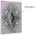
图1为以垂直的观察角度拍摄的一个印刷物品的照片;Figure 1 is a photograph of a printed article taken at a vertical viewing angle;
图2为以第一观察角度拍摄的图1中所示印刷物品的照片;Figure 2 is a photograph of the printed article shown in Figure 1 taken at a first viewing angle;
图3为以第二观察角度拍摄的图1中所示印刷物品的照片;Figure 3 is a photograph of the printed article shown in Figure 1 taken at a second viewing angle;
图4为一磁铁的示意图;4 is a schematic diagram of a magnet;
图5为由图4所示磁铁产生的磁场的示意图;Figure 5 is a schematic diagram of the magnetic field generated by the magnet shown in Figure 4;
图6为使用图4所示磁铁形成的一个图像的示意图;Figure 6 is a schematic diagram of an image formed using the magnet shown in Figure 4;
图7为使用图4所示磁铁形成的图像的横截面的示意图;7 is a schematic diagram of a cross-section of an image formed using the magnet shown in FIG. 4;
图8为图7所示横截面内由薄片形成的角度变化图;FIG. 8 is a view of the angle change formed by the sheet in the cross section shown in FIG. 7;
图9为由使用图4所示磁铁排列的薄片所形成的一个反射表面的图示;FIG. 9 is an illustration of a reflective surface formed by sheets using the magnet arrangement shown in FIG. 4;
图10为包括四个图4所示磁铁的磁性组件的示意图;10 is a schematic diagram of a magnetic assembly including four magnets shown in FIG. 4;
图11为由使用图10所示磁性组件排列的薄片所形成的一个反射表面的图示;Fig. 11 is an illustration of a reflective surface formed by sheets arranged using the magnetic assembly shown in Fig. 10;
图12为以垂直的观察角度拍摄的一个印刷物品的照片;Figure 12 is a photograph of a printed article taken at a vertical viewing angle;
图13为以第一观察角度拍摄的一个印刷物品的照片;Figure 13 is a photograph of a printed article taken at a first viewing angle;
图14为以第二观察角度拍摄的一个印刷物品的照片;Figure 14 is a photograph of a printed article taken at a second viewing angle;
图15为一个磁性组件的示意图;Figure 15 is a schematic diagram of a magnetic assembly;
图16和16A为由图15所示磁性组件产生的磁场的示意图;Figures 16 and 16A are schematic diagrams of the magnetic field produced by the magnetic assembly shown in Figure 15;
图17为由使用图15所示磁性组件排列的薄片所形成的一个反射表面的图示;图18为由图15所示磁性组件产生的磁场的示意图;Figure 17 is an illustration of a reflective surface formed by sheets arranged using the magnetic assembly shown in Figure 15; Figure 18 is a schematic illustration of the magnetic field produced by the magnetic assembly shown in Figure 15;
图19为以接近垂直的观察角度拍摄的一个印刷物品的照片;Figure 19 is a photograph of a printed article taken at a near-vertical viewing angle;
图20为以第一观察角度拍摄的一个印刷物品的照片;Figure 20 is a photograph of a printed article taken at a first viewing angle;
图21为以第二观察角度拍摄的一个印刷物品的照片;Figure 21 is a photograph of a printed article taken at a second viewing angle;
图22为一个磁性组件的示意图;Figure 22 is a schematic diagram of a magnetic assembly;
图23和图24为一个印刷物品的照片;Figures 23 and 24 are photographs of a printed article;
图25为一个磁性组件的示意图;Figure 25 is a schematic diagram of a magnetic assembly;
图26-28为一个印刷物品的照片;Figures 26-28 are photos of a printed item;
图29为一个磁性组件的示意图;Figure 29 is a schematic diagram of a magnetic assembly;
图30为在图29所示磁性组件中使用的托架的示意图;Figure 30 is a schematic diagram of a bracket used in the magnetic assembly shown in Figure 29;
图31为一个磁场的示意图;Figure 31 is a schematic diagram of a magnetic field;
图32为在一个磁性组件中使用的托架的示意图;Figure 32 is a schematic diagram of a bracket used in a magnetic assembly;
图33为一个磁场的示意图;Figure 33 is a schematic diagram of a magnetic field;
图33A为一个印刷物品的照片;Figure 33A is a photograph of a printed article;
图34为一个磁场的示意图;Figure 34 is a schematic diagram of a magnetic field;
图35为一个磁场的示意图;Figure 35 is a schematic diagram of a magnetic field;
图36为一个磁性组件的示意图;Figure 36 is a schematic diagram of a magnetic assembly;
图37为一个印刷物品的照片;Figure 37 is a photograph of a printed article;
图38为一个磁性组件的示意图;Figure 38 is a schematic diagram of a magnetic assembly;
图39和图40为一个印刷物品的照片;Figures 39 and 40 are photographs of a printed article;
图41为一个磁性组件的示意图;Figure 41 is a schematic diagram of a magnetic assembly;
图42和图43为一个印刷物品的照片;Figures 42 and 43 are photographs of a printed article;
图44为一个磁性组件的示意图;Figure 44 is a schematic diagram of a magnetic assembly;
图45和图46为一个印刷物品的照片;Figures 45 and 46 are photographs of a printed article;
图47至图50为一个印刷物品的照片。Figures 47 to 50 are photographs of a printed article.
具体实施方式Detailed ways
发明人在对新的印刷装置的研究中发现了一种此前未知的效应,该新的印刷装置可提供高辨识度的动态光学效果。已经发现,通过其对角线磁化的正方形磁铁可以排列可磁性排列的颜料片,以产生人的裸眼可见的“回力镖”光学效应,如图1-3所示。The inventors discovered a previously unknown effect in their research on a new printing device that provides highly recognizable dynamic optical effects. It has been found that a square magnet magnetized by its diagonal can align magnetically alignable pigment flakes to produce a "boomerang" optical effect visible to the naked human eye, as shown in Figures 1-3.
参考图4,正方形磁铁通过其对角线进行磁化;磁场的磁力线如图5所示。磁力线的半径在整个磁铁上变化。由此,由颜料片形成的排列的半径也会变化,这将形成一个同时运动并逐步改变其形状的动态图像。Referring to Figure 4, a square magnet is magnetized through its diagonal; the magnetic field lines of the magnetic field are shown in Figure 5. The radii of the magnetic field lines vary across the magnet. As a result, the radius of the arrangement formed by the pigment flakes also changes, which creates a dynamic image that moves simultaneously and gradually changes its shape.
当在基底的表面上施加含有可磁性排列的薄片的油墨或涂料、且薄片采用图4所示的磁铁进行排列时,薄片会形成一个排列图案,这可以参考图6和图7进行描述。基底100有底部磁铁的假想轮廓110,磁铁的磁极以“N”和“S”表示;在沿NS线切割出的印刷图像的横截面200(图6)中,可磁性排列的薄片形成弯曲图案。图7所示的另外两个横截面201和202平行于横截面200,在图6中以线121和122示意性示出。尤其是在横截面201和202内,可磁性排列的薄片也形成弯曲图案,但其特征在于半径比横截面200内的要小。When an ink or paint containing magnetically alignable flakes is applied on the surface of the substrate, and the flakes are aligned with the magnet shown in FIG.
一般而言,在与位于点A与B之间的连续假想线130垂直的横截面内,可磁性排列的薄片形成一个弯曲图案,其中弯曲图案的半径在沿假想线从A移动到B时会增大,其中在涂层的横截面内由薄片形成的弯曲图案的半径被视为由薄片的头尾连接形成的曲线的平均半径。优选的是,弯曲图案的半径在进一步沿假想线移动(即超过点B)后会减小(图6),使得跨假想对称轴移动的亮的图像包括完整的双叉回力镖图形。在例如采用非磁性油墨印刷的底层图像包括符号或标记或其他任何局部化图像,而亮的回力镖看上去运动、可能有时部分覆盖住图像的情况下,具有完整的回力镖图形就特别有利。In general, in a cross-section perpendicular to a continuous
油墨或涂料内可磁性排列的薄片的重量浓度可能在4%至25%之间,优选为4%至14%之间,以使底层图形图案或纯色背景在与该亮的图像相邻的区域内可见,即目的是使该亮的图像外围的阴影最小化。已经发现了一种反直觉的情况,即,采用稀释油墨印刷的亮的动态图像比采用高浓度油墨印刷的框架具有更明确限定的形状,且更容易与背景相区分。显然,稀释的磁性油墨允许去除多余的效应和阴影。特别是,其上加印有低浓度磁性油墨的背景几乎在每处均透过磁性油墨可见,只有可磁性排列的薄片以预定方式排列,以使反射光会聚形成亮的图像的区域例外。The weight concentration of the magnetically alignable flakes in the ink or paint may be between 4% and 25%, preferably between 4% and 14%, so that the underlying graphic pattern or solid color background is in the area adjacent to the bright image Visible within, ie the aim is to minimize shadows at the periphery of this bright image. It has been found counter-intuitive that a bright dynamic image printed with diluted ink has a more well-defined shape and is more easily distinguishable from the background than a frame printed with high concentration ink. Apparently, the diluted magnetic ink allows removal of unwanted effects and shadows. In particular, the background on which the low concentration magnetic ink is imprinted is visible through the magnetic ink almost everywhere except in the areas where the magnetically alignable flakes are arranged in a predetermined manner so that the reflected light converges to form a bright image.
为使反射光聚焦或会聚,磁性反射片排列成一个弯曲图案,使得图案的横截面包括在由假想线130限定的图案的中心部分内平行于基底排列的薄片,还包括被倾斜的薄片,以使薄片与基底之间的角度在从假想线130到图案外边缘的方向上逐渐增大。薄片可被视为形成将反射光会聚成观察者可见的亮的图像的菲涅耳反射器。已经被证明的是,重量浓度在4%至14%范围内的稀释油墨可以提供由经排列的反射薄片的聚焦图案形成的足以辨识的图像。To focus or concentrate the reflected light, the magnetic reflective sheets are arranged in a curved pattern such that the cross-section of the pattern includes sheets aligned parallel to the substrate in the central portion of the pattern defined by the
基底表面上的连续假想线130由下面的磁铁确定,且与用于排列薄片的磁铁的表面上的磁力线正交。直接位于连续假想线130上方的一部分可磁性排列的薄片沿线段AB和BC平行于基底。A continuous
图8为图7所示横截面200内由可磁性排列的薄片形成的角度变化图,即沿图5所示磁铁的从南极到北极的方向。薄片可以被排列成使得在多个横截面中的大部分或至少一个之内,磁性排列的薄片与基底所形成的夹角从在假想线上的零度增大到假想线两侧的80度,优选达到85度,理想情况下则达到垂直方向(90度),如图8所示,此结果借助集成工程软件公司(Integrated Engineering Software,integratedsoft.com)所提供的三维磁场解算程序Amperes对所述磁铁形成的磁场进行计算机仿真而得出。FIG. 8 is a graph of the angle variation formed by the magnetically alignable sheets within the
为使回力镖光学效应可被人的裸眼看见,颜料片的图案应有足够的尺寸。例如,位于倾斜角为80度的两个点之间的的最大横截面200内的弯曲图案的宽度优选处于8至25mm的范围内。In order to make the optical effect of the boomerang visible to the naked eye, the pattern of the pigment flakes should be of sufficient size. For example, the width of the curved pattern within the
图9示出了一个三维反射表面,由在图4所示磁铁的磁场中排列的薄片在薄片以首尾相接方式连接时形成。该反射表面示出了上述参考横截面200至202所讨论的半径的变化情况。FIG. 9 shows a three-dimensional reflective surface formed by lamellae aligned in the magnetic field of the magnet shown in FIG. 4 when the lamellae are connected end-to-end. The reflective surface shows the change in radius discussed above with reference to cross-sections 200 to 202 .
图1至3所示为从多个角度拍摄的最终形成的物品的照片,这样自然可以产生与将物品相对于光源倾斜而观察者保持静止的方式相同的效果。当光从光源入射到可磁性排列的薄片上时,从物品反射的光形成一个看上去逐渐改变其形状的弯曲的亮的图像,其在某个时刻像回力镖,并逐渐靠近线130,以便在基底相对光源倾斜时,从假想线130的一侧移动至假想线的另一侧。连续假想线130为对称轴,亮的虚幻图像在此对称轴处逐渐翻转,由此连续假想线130限定该图像。Figures 1 to 3 show photographs of the resulting article taken from various angles, which naturally produce the same effect as if the article were tilted relative to the light source while the observer remained stationary. When light is incident on the magnetically alignable sheet from a light source, the light reflected from the item forms a curved bright image that appears to gradually change its shape, like a boomerang at some point, and gradually approach
可选的,物品包括至少一个印刷或涂覆的背景,以提供含有非磁性颜料的涂层,使亮的图像看上去相对于背景运动。优选的是,下面的非磁性涂层提供一个图像,且弯曲图案的半径沿连续假想线先增大后减小,使亮的图像从图像的一侧移动至另一侧,如图1至3所示。Optionally, the article includes at least one printed or coated background to provide a coating containing a non-magnetic pigment to make the bright image appear to move relative to the background. Preferably, the underlying non-magnetic coating provides an image with the radius of the curved pattern increasing and then decreasing along a continuous imaginary line, moving the bright image from one side of the image to the other, as shown in Figures 1 to 3 shown.
在上述具体实例中,涂层的横截面内由薄片形成的弯曲图案为凸面图案;而其他的磁场布置或印刷技术也可能会形成凹面图案。作为举例,可在透明的塑料支撑物上施加磁性油墨或涂料;磁性排列的薄片可由图4所示的磁铁进行排列,随后可将塑料支撑物应用到文件或其他物体上,其印刷一侧与文件表面相邻,如参照图19至21所进一步讨论的。对于看向文件或物体的观察者而言,磁性排列的薄片会在油墨的横截面内形成一个凹面图案,亮的图像也会逐渐改变其形状,从假想线的一侧翻转至假想线的另一侧,以此形成回力镖效应。In the above specific example, the curved pattern formed by the flakes in the cross section of the coating is a convex pattern; other magnetic field arrangements or printing techniques may also form a concave pattern. As an example, a magnetic ink or paint can be applied to a transparent plastic support; the magnetically aligned flakes can be aligned by a magnet as shown in Figure 4, and the plastic support can then be applied to a document or other object with a printed side that matches the The document surfaces are adjacent, as discussed further with reference to Figures 19-21. To an observer looking at a document or object, the magnetically aligned flakes create a concave pattern within the cross-section of the ink, and the bright image gradually changes its shape, flipping from one side of the imaginary line to the other side of the imaginary line. side to form a boomerang effect.
此外,还有多种磁铁可用于替代正方形磁铁,包括具有平行于磁铁磁轴的平坦表面(例如圆形或菱形)的磁铁。对于对称型磁铁或磁性组件,假想线为一直线,用作移动的图像的对称轴。对于非对称型磁铁,其上薄片平行于基底排列的假想线为曲线。In addition, there are a variety of magnets that can be used in place of square magnets, including magnets with flat surfaces (eg, circles or diamonds) that are parallel to the magnet's magnetic axis. For symmetrical magnets or magnetic assemblies, the imaginary line is a straight line that serves as the axis of symmetry for the moving image. For asymmetrical magnets, the imaginary line on which the lamellae are aligned parallel to the base is a curve.
多个磁铁组装在一起形成的组合可基于前面所讨论的可磁性排列的薄片的排列而产生更为复杂的光学效应。参见图10,磁性组件包括组装在一起的四个完全相同的正方形磁铁;四个磁铁的尺寸和对角线磁化均相同,如图4所示,并由托架(未示出)固定在一起。图11示出了由在图10所示组件的磁场中排列的可磁性排列的薄片的头尾连接所产生的一个反射表面。Combinations of multiple magnets assembled together can produce more complex optical effects based on the arrangement of the magnetically alignable sheets discussed above. Referring to Figure 10, the magnetic assembly consists of four identical square magnets assembled together; the four magnets are identical in size and diagonal magnetization, as shown in Figure 4, and are held together by brackets (not shown) . FIG. 11 shows a reflective surface created by the head-to-tail connection of magnetically alignable sheets aligned in the magnetic field of the assembly shown in FIG. 10 .
图12至图14为所形成的物品的照片,其中可磁性排列的薄片借助图10所示的磁性组件实现排列。这些照片由照相机从多个角度拍摄,这样可以产生与将物品相对于光源倾斜而观察者保持静止的方式相同的效果。这些照片呈现出一种凸面“精灵羽翼”(FairyWings)光学效应。图片系在不同的观察角度拍摄。图12所示为垂直观察角度下的物品。图13示出了上边缘倾斜远离照相机方向的物品,而图14则示出了上边缘朝向照相机方向倾斜的情况。物品在倾斜时呈现出精灵拍打羽翼的效果。FIGS. 12-14 are photographs of the formed articles in which the magnetically alignable sheets are aligned by means of the magnetic assembly shown in FIG. 10 . These photos are taken by the camera from multiple angles, which produces the same effect as if the object were tilted relative to the light source while the viewer remained stationary. The photos show a convex "Fairy Wings" optical effect. The pictures were taken at different viewing angles. Figure 12 shows the item at a vertical viewing angle. Figure 13 shows the item with the top edge slanted away from the camera, while Figure 14 shows the top edge slanted towards the camera. The item has the effect of a elf flapping its wings when tilted.
参见图15,四个磁铁组成的组件有一个经组件中心切割的锥形切割部分。图16示出了磁场沿对角线D(图15)的横截面图,对角线D表示磁性组件的无效区;沿此对角线的磁通密度几乎为零。图16A示出了垂直于对角线D的一个横截面内的磁场。图17所示为一个三维反射表面,其由在图15所示的磁性组件的磁场中排列的薄片在其以首尾相连方式连接时形成。反射表面的半径变化如图9所示。相应地,图15所示组件可被用于排列可磁性排列的薄片,以形成一个图像,使从所排列的图案上反射的光形成一个亮的图像,当基底相对光源倾斜时,该亮的图像看上去逐步改变其形状、并从连续假想线的一侧移动至连续假想线的另一侧,如图19至图21所示。Referring to Figure 15, the assembly of four magnets has a tapered cut portion cut through the center of the assembly. Figure 16 shows a cross-sectional view of the magnetic field along diagonal D (Figure 15), which represents the dead zone of the magnetic assembly; the magnetic flux density along this diagonal is almost zero. FIG. 16A shows the magnetic field in a cross-section perpendicular to the diagonal D. FIG. Figure 17 shows a three-dimensional reflective surface formed from sheets aligned in the magnetic field of the magnetic assembly shown in Figure 15 when they are connected end-to-end. The change in radius of the reflective surface is shown in Figure 9. Accordingly, the assembly shown in Figure 15 can be used to align magnetically alignable sheets to form an image such that light reflected from the aligned pattern forms a bright image that is brighter when the substrate is tilted relative to the light source. The image appears to gradually change its shape and move from one side of the continuous imaginary line to the other side of the continuous imaginary line, as shown in Figures 19-21.
图9、图11和图17中反射表面的特征在于其半径的变化。图18示出,沿一条直的假想线,薄片排列的半径最初为增大,例如半径从R1增大到R2(R2>R1),然后再减小。当然,还可采用其他的半径变化形式。The reflective surfaces of Figures 9, 11 and 17 are characterized by a change in their radius. Figure 18 shows that along a straight imaginary line, the radius of the flake arrangement is initially increasing, eg, the radius increases from R1 to R2 (R2>R1), and then decreases again. Of course, other radius variations can also be used.
图19至图21为所形成的物品的照片,其中可磁性排列的薄片采用图15所示的磁性组件进行排列。这些照片由照相机从多个角度拍摄,这样可以产生与将物品相对于光源倾斜而观察者保持静止的方式相同的效果。这些照片示出了一种由薄片的凹面排列所形成的“回力镖”光学效应,其制作方式为:将重量浓度为5%的金/绿闪光(Gold/Green Spark)油墨印刷到一个薄的透明聚酯片上,将油墨暴露到图15所示磁铁的磁场内,使用紫外线对油墨进行固化,并对薄片进行层压,使其印刷面与纸质基底的安全底纹团花(Guillocherosette)邻接。FIGS. 19-21 are photographs of the formed article in which the magnetically alignable sheets are aligned using the magnetic assembly shown in FIG. 15 . These photos are taken by the camera from multiple angles, which produces the same effect as if the object were tilted relative to the light source while the viewer remained stationary. These photographs show a "boomerang" optical effect created by the concave arrangement of flakes, produced by printing 5% by weight Gold/Green Spark ink onto a thin On a transparent polyester sheet, the ink is exposed to the magnetic field of the magnet shown in Figure 15, the ink is cured using UV light, and the sheet is laminated so that the printed side is adjacent to the Guillocherosette of the paper base .
参见图19,在接近直角的观察角度上,物品的中部呈现出一条亮线。该亮线中部区域较宽,两端则逐渐变细。图20示出向左侧倾斜的物品,图21则为向右侧倾斜。在左侧和右侧倾斜时,亮的图像呈现为回力镖的形状。当样品从左侧(右侧)向右侧(左侧)倾斜时,它开始是一个回力镖形(图20),然后在角度变为直角时变为一条两端渐细的直线(图19),之后当样品倾斜到右侧时,再次变为回力镖(图21)。Referring to Figure 19, at a near-right viewing angle, a bright line appears in the middle of the article. The bright line is wider in the middle and tapered at both ends. Figure 20 shows the item tilted to the left, and Figure 21 is tilted to the right. When tilted to the left and right, the bright image takes on the shape of a boomerang. As the sample is tilted from the left (right) to the right (left), it starts out as a boomerang (Fig. 20) and then becomes a straight line tapering at both ends as the angle becomes right (Fig. 19) ), then when the sample is tilted to the right, it becomes a boomerang again (Figure 21).
图19-图21中的照片示出了一种可用于防伪应用的非常有吸引力、引人注目的效应。The photographs in Figures 19-21 illustrate a very attractive, eye-catching effect that can be used in anti-counterfeiting applications.
参见图22,另一个四磁铁组件有一个经组件中心切出的角锥形切出部分。图23中示出了印刷在一个黑色背景上、重量浓度为15%的油墨中的“尖峰”(Spike)光学效应的外观。然而,当颜料的重量浓度降至5%且油墨被涂覆到带有安全图形的纸上时,该图像将变得更加有吸引力,如图24所示。Referring to Figure 22, another four-magnet assembly has a pyramid-shaped cutout through the center of the assembly. The appearance of the "Spike" optical effect in 15% by weight ink printed on a black background is shown in Figure 23. However, when the weight concentration of the pigment was reduced to 5% and the ink was applied to the paper with the security graphic, the image became more attractive, as shown in Figure 24.
参见图25,一个磁性组件包括偏转器,其可能是高磁导率或中等磁导率的薄片。偏转器的用途是将磁场从其原始方向偏转至预定的方向。图25所示的偏转器是一个具有高磁导率的金属薄片(镍铁钼超导磁合金、(mu-metal)高导磁率合金、坡莫合金等)。偏转器的厚度可以在很大范围内变化,并由磁场的配置和磁铁的等级确定。图25所示的中心有正方形切口的偏转器采用0.006英寸厚的高导磁率合金片制成。该偏转器被直接置于图22所示磁铁的顶部。之前用含有分散的磁片的湿油墨涂覆的纸质基底被置于该偏转器的顶部。Referring to Figure 25, one magnetic assembly includes a deflector, which may be a high or medium permeability sheet. The purpose of the deflector is to deflect the magnetic field from its original direction to a predetermined direction. The deflector shown in FIG. 25 is a metal flake with high magnetic permeability (nickel-iron-molybdenum superconducting magnetic alloy, (mu-metal) high permeability alloy, permalloy, etc.). The thickness of the deflector can vary widely and is determined by the configuration of the magnetic field and the grade of the magnet. The deflector shown in Figure 25 with a square cut in the center was fabricated from a 0.006 inch thick sheet of high permeability alloy. The deflector is placed directly on top of the magnet shown in Figure 22. A paper substrate previously coated with wet ink containing dispersed magnetic flakes was placed on top of the deflector.
在磁片排列完成之后,采用紫外线对油墨进行固化。其结果是,经排列的磁片形成了一个凸面反射表面。偏转器对正方形切口的边缘周围的磁场进行偏转,对切口边缘处的磁片以不同的方式进行排列。参见图26,一个印刷图形部件包括底纹团花(Guillocherosette)、暗色菱形和位于团花中心的数字。该菱形的尺寸与偏转器内的切口尺寸相同。该图形部件之上印刷有磁性油墨,油墨内的可磁性排列的薄片采用图25所示的磁性组件进行排列。从偏转器边缘周围偏转的磁片生成了该图形图像的轮廓。图26中物品的图形部件包括多个底纹图案和一个印刷在图形部件中心的暗色菱形,菱形的中心有一个与之形成反差的白色数字“10”。图26示出观察角度为直角时印有图形和光学部件的物品。其效果呈现为一个有光泽的菱形,有两个点从其上以相反方向出现。磁性排列的菱形看上去不透明,会掩盖住在磁性排列的光学部件下方印刷的菱形图。当样品以右边缘远离观察者的方式倾斜时,磁性排列效果会改变(图27)。此时,不透明的菱形会变为透明,有一个亮的箭头呈现出印刷菱形图形的轮廓。带有数字“10”的印刷菱形图的辨识度非常高。当样品以左边缘远离观察者的方式倾斜时,此效果会以相反方向移动(图28)。图26至图28示出回力镖(或“侧转”)效果,其外观为纺锤形,中部最宽,顶部和底部逐渐变细。该亮的图像逐渐改变其形状,并从印刷图像的中央纵(相对于图纸)轴的左侧翻转至该轴线的右侧。此效果由薄片的弯曲排列实现,其中,沿中央纵轴的薄片平行于基底排列,而在垂直于该纵轴的横截面内,薄片形成拱形图案,拱形的半径沿该轴线先增大后减小。图26-图28所示的与该菱形的两个侧边相邻的箭头特征在样品倾斜时会接触到回力镖。位置靠近穿过磁偏转器的切口的边缘的部分薄片被局部扭曲,这将导致图形部件的菱形元素的箭头状轮廓的外观。After the magnetic sheets are aligned, the ink is cured with UV light. As a result, the aligned magnetic sheets form a convex reflective surface. The deflector deflects the magnetic field around the edges of the square cutouts, aligning the magnetic sheets in different ways at the edges of the cutouts. Referring to Figure 26, a printed graphic element includes a shaded tulle (Guillocherosette), a dark diamond, and a number in the center of the tulle. The size of the diamond is the same as the size of the cutout in the deflector. Magnetic ink is printed on the graphic part, and the magnetically alignable flakes in the ink are arranged using the magnetic assembly shown in FIG. 25 . The contours of this graphic image are generated from magnetic sheets deflected around the edge of the deflector. The graphic element of the article of Figure 26 includes a plurality of shading patterns and a dark diamond printed in the center of the graphic element with a contrasting white number "10" in the center of the diamond. Figure 26 shows an article with printed graphics and optics when viewed at a right angle. The effect appears as a shiny diamond with two points emerging from it in opposite directions. The magnetically aligned diamonds appear opaque and obscure the printed diamond pattern underneath the magnetically aligned optics. When the sample is tilted with the right edge away from the viewer, the magnetic alignment effect changes (Figure 27). At this point, the opaque diamond becomes transparent, with a bright arrow that outlines the printed diamond graphic. The printed diamond with the number "10" is very recognizable. This effect moves in the opposite direction when the sample is tilted with the left edge away from the viewer (Figure 28). Figures 26-28 show the boomerang (or "spin") effect, which has a spindle-shaped appearance, widest in the middle and tapering at the top and bottom. The bright image gradually changes its shape and flips from the left side of the central longitudinal (relative to the drawing) axis of the printed image to the right side of that axis. This effect is achieved by a curved arrangement of the lamellae, wherein the lamellae along a central longitudinal axis are aligned parallel to the substrate, while in cross-section perpendicular to this longitudinal axis the lamellae form an arched pattern, the radius of the arches increasing first along this axis decrease later. The arrow features shown in Figures 26-28 adjacent to the two sides of the rhombus contact the boomerang when the sample is tilted. Parts of the sheet located close to the edge of the cut through the magnetic deflector are locally distorted, which results in the appearance of an arrow-like outline of the diamond-shaped element of the graphic part.
上文已经示出,可采用多种磁铁和磁性组件以产生由基底表面上的假想线所限定的回力镖效应,其中从光源入射到可磁性排列的薄片上的光被物品反射,形成弯曲的亮区,当基底相对光源倾斜时,所述亮区表现为逐步改变其形状,并从假想线的一侧移动至假想线的另一侧。可磁性排列的薄片被排列,以形成由假想线确定的图像,使得在位于假想线的第一点与第二点之间的与假想线垂直的多个横截面之内,可磁性排列的薄片形成一个凹面或凸面图案,其中凹面或凸面图案的半径沿假想线从第一点到第二点增大。优选情况为,在经过第二点之后半径减小,以形成完整的回力镖,其看上去为一个弯的亮的轮廓框架,中部较宽而端部逐渐变细。不过,作为举例,可以仅在磁铁下半部分上印刷磁性油墨(参见图4),这将形成半回力镖效应,其同样具备高的辨识度,可用于防伪目的。It has been shown above that a variety of magnets and magnetic assemblies can be employed to create the boomerang effect defined by imaginary lines on the surface of the substrate, wherein light incident on the magnetically alignable sheet from a light source is reflected by the item, creating a curved Bright areas, which appear to gradually change their shape and move from one side of the imaginary line to the other side of the imaginary line when the substrate is tilted relative to the light source. The magnetically alignable flakes are aligned to form an image defined by an imaginary line such that within a plurality of cross-sections perpendicular to the imaginary line between a first point and a second point of the imaginary line, the magnetically alignable flakes A concave or convex pattern is formed wherein the radius of the concave or convex pattern increases along an imaginary line from a first point to a second point. Preferably, the radius decreases after the second point to form a complete boomerang which appears as a curved bright profile frame, wider in the middle and tapering at the ends. However, as an example, the magnetic ink can be printed only on the lower half of the magnet (see Figure 4), which will create a half boomerang effect, which is also highly recognizable and can be used for anti-counterfeiting purposes.
参见图29,一个磁性组件包括四个压制粘结的可机加工钕铁硼磁铁,已按图29所示进行切割,并由图30所示托架固定在一起。磁铁的顶面排列成锯齿形线。四个磁铁中的每一个的北极和南极均在磁铁的侧表面上。相应地,当粘结剂中含有可磁性排列的薄片的涂层被印刷到基底上,然后基底又被置于图30所示组件的顶上时,在每一段锯齿线上方,薄片被排列成使垂直于锯齿线段的横截面具有薄片排列200(图7)。磁性组件在基底表面上限定一条假想的连续锯齿线,且在该假想连续锯齿线上的两点之间垂直于该线的多个横截面之内,可磁性排列的薄片与基底形成的夹角先减小到零,然后再增大。对应于由图30所示组件产生的薄片排列的反射表面在图31中示意性示出。可磁性排列的薄片被排列以形成一个已排列的图案,其中一部分可磁性排列的薄片沿基底表面上的一条连续假想线上的第一点与第二点之间的部分平行于基底,可磁性排列的薄片在垂直于连续假想线的多个横截面内形成弯曲图案,且其中连续假想线在第一点与第二点之间为锯齿线或波形线。Referring to Figure 29, a magnetic assembly includes four press-bonded, machineable NdFeB magnets that have been cut as shown in Figure 29 and held together by the bracket shown in Figure 30. The top surfaces of the magnets are arranged in a zigzag line. The north and south poles of each of the four magnets are on the side surfaces of the magnets. Correspondingly, when a coating containing magnetically alignable flakes in a binder is printed onto a substrate, which is then placed on top of the assembly shown in Figure 30, over each segment of the zigzag line, the flakes are aligned in a A cross section perpendicular to the zigzag line segment is made to have a lamella arrangement 200 (FIG. 7). The magnetic assembly defines an imaginary continuous zigzag line on the surface of the substrate, and within a plurality of cross-sections perpendicular to the line between two points on the imaginary continuous zigzag line, the included angle formed by the magnetically alignable sheet and the substrate Decrease to zero first, then increase. A reflective surface corresponding to the lamella arrangement produced by the assembly shown in FIG. 30 is shown schematically in FIG. 31 . The magnetically alignable flakes are arranged to form an aligned pattern in which a portion of the magnetically alignable flakes is parallel to the substrate along the portion between the first point and the second point on a continuous imaginary line on the surface of the substrate, which is magnetically alignable. The aligned sheets form a curved pattern in a plurality of cross-sections perpendicular to a continuous imaginary line, and wherein the continuous imaginary line is a zigzag or wavy line between a first point and a second point.
所形成的图像可以被视为锯齿形或波浪形滚动条。当光从光源入射到可磁性排列的薄片上时,从物品反射的光形成一个亮的锯齿形或波浪形,其在基底相对光源倾斜时看上去是运动的。亮锯齿形可包括至少三段。薄片可以被排列成使得在多个横截面中的大部分或至少一个之内,磁性排列的薄片与基底所形成的夹角从在假想线上的零度增大到在假想线两侧上的80度。为使动态锯齿形或曲线光学效应可被人的裸眼看见,颜料片的排列图案应有足够的尺寸。例如,位于倾斜角为80度的两个点之间的横截面内的弯曲图案的宽度优选处于3mm至20mm的范围内。The resulting image can be seen as a zig-zag or wavy scroll bar. When light is incident on the magnetically alignable sheet from the light source, the light reflected from the article forms a bright sawtooth or wave shape that appears to move when the substrate is tilted relative to the light source. The bright sawtooth shape may include at least three segments. The lamellae may be arranged such that the angle formed by the magnetically aligned lamellae and the substrate increases from zero degrees on the imaginary line to 80 degrees on either side of the imaginary line over most or at least one of the plurality of cross-sections. Spend. In order to make the dynamic zigzag or curved optical effect visible to the naked eye, the arrangement pattern of the pigment flakes should be of sufficient size. For example, the width of the curved pattern in the cross-section between two points with an inclination angle of 80 degrees is preferably in the range of 3 mm to 20 mm.
参见图32,一种形成印刷物品的方法包括使用在托架2之间被弯曲的柔性磁铁的堆叠1,以形成一个锯齿形或波浪形。磁铁可以是由Electrodyne公司提供的PlastalloyTM(橡胶黏合式锶铁氧体)或ReanceTM F和ReanceTM SF柔性钕磁铁。波浪形滚动条的磁场分布在图33的示意图以及图33A的照片中示出。Referring to Figure 32, one method of forming a printed article involves using a stack 1 of flexible magnets that are bent between
薄的柔性磁铁的叠层允许形成滚动条半径相同的许多奇形怪状的滚动条效应。此外,采用多种尺寸、在托架之间被夹持和弯曲的柔性磁铁可以形成弯曲的滚动条,其中薄片排列的半径沿限定滚动条的曲线变化。The stack of thin flexible magnets allows the creation of many odd-shaped scroll bar effects with the same scroll bar radius. In addition, flexible magnets of various sizes, clamped and bent between brackets, can form curved roll bars, wherein the radii of the sheet arrangements vary along the curve defining the roll bar.
以下说明和具体细节涉及本文所述的所有实施方式。The following description and specific details refer to all embodiments described herein.
基底可以为纸、塑料或硬纸板基底等,所得的物品可以是钞票、信用卡或其上按本文所述方式施加了可磁性排列的薄片的任何其他物体。The substrate may be a paper, plastic or cardboard substrate, etc., and the resulting article may be a banknote, a credit card, or any other object to which a magnetically alignable sheet has been applied in the manner described herein.
在磁性油墨被印刷到一种塑料基底(例如透明聚酯)上的实施方式中,基底上可以有透明的全息图,带有符号或图案,其可与基底的图案在图形上相匹配。全息图优选涂覆有一种高折射率材料。加入全息图可以为器件提供附加的防伪特征,因为器件的生产不仅涉及防伪印刷和磁性排列方面的技术,还涉及制作全息图的技术。In embodiments where the magnetic ink is printed on a plastic substrate (eg, transparent polyester), the substrate may have a transparent hologram with symbols or patterns that may match graphically with the pattern of the substrate. The hologram is preferably coated with a high refractive index material. The addition of a hologram can provide an additional security feature to the device, as the production of the device involves technology not only in security printing and magnetic alignment, but also in making the hologram.
上述物品可以被用作光学防伪装置,可以有两个部件:图形部件和光学部件,光学部件可能位于图形部件的顶部,并可被集成到钞票或防伪标签内。图形部件可以包括文件防伪行业中使用的防伪图案之一和/或图画或符号。光学部件可采用变色干涉颜料或反射性金属颜料片制成。光学部件可增强图形部件的外观。光学部件从分散于粘结剂内并沿所施加磁场的磁力线排列的磁性颜料(薄片)的凹面、凸面、双凸面或半凸半凹面等布置上对光进行反射。粘结剂为透光型,优选为透明的、可采用紫外线固化的粘结剂。粘结剂内的颗粒重量浓度优选在4%-14%范围内,以使含有可磁性排列的薄片的涂层的大部分为透明,底层图形部件是可见的。低浓度涂层仅在薄片以弯曲图案排列并可能将反射光在预定方向聚焦的区域内提供亮的图像,例如回力镖形或锯齿形图像。薄片的低浓度(重量浓度在4%-14%之间)可用于消除或至少最大限度地减少亮的回力镖形、锯齿形或波浪形图像的阴影。The above article can be used as an optical security device and can have two parts: a graphic part and an optical part, the optical part may be located on top of the graphic part and can be integrated into a banknote or security label. The graphic component may include one of the security patterns and/or drawings or symbols used in the document security industry. Optical components can be made with color-changing interference pigments or reflective metallic pigment flakes. Optical components enhance the appearance of graphic components. Optical components reflect light from concave, convex, biconvex or semi-convex semi-concave arrangements of magnetic pigments (flakes) dispersed within the binder and aligned along the lines of magnetic force of the applied magnetic field. The adhesive is a light-transmitting, preferably transparent, UV-curable adhesive. The particle weight concentration in the binder is preferably in the range of 4% to 14% so that the majority of the coating containing the magnetically alignable flakes is transparent and the underlying graphic features are visible. Low concentration coatings provide bright images, such as boomerang or zigzag images, only in areas where the flakes are arranged in a curved pattern and may focus reflected light in a predetermined direction. Low concentrations of flakes (between 4% and 14% by weight) can be used to eliminate or at least minimize shadows from bright boomerang, zigzag or wavy images.
两种部件均可采用常规技术印刷。图形和由光学部件产生的光学效应应该相互补充。光学部件可以设置在图形的顶部或其下方。光学部件可以被涂覆为图案,也可被涂覆为连续层。光学部件可以是凸面反射器(当采用湿式磁性油墨印刷的基底被置于磁铁顶部时)或凹面反射器(当采用湿式磁性油墨印刷的透明聚合物薄片被置于磁铁顶部、薄片在磁场中被排列、油墨被固化且透明薄片以印刷侧与图形图像贴附的方式被层压时)或凹面反射器与凸面反射器组合的形式。Both parts can be printed using conventional techniques. The graphics and the optical effects produced by the optical components should complement each other. Optical components can be placed on top of the graphic or below it. Optical components can be coated as a pattern or as a continuous layer. The optical component can be a convex reflector (when a substrate printed with wet magnetic ink is placed on top of a magnet) or a concave reflector (when a transparent polymer sheet printed with wet magnetic ink is placed on top of the magnet, the sheet is arrangement, the ink is cured and the transparent sheet is laminated with the print side attached with the graphic image) or in the form of a combination of concave and convex reflectors.
图形部件和光学部件可采用相同颜色的颜料印刷。优选情况是,由光学部件产生的光学效应仅会阻挡住整个区域中的一小部分,将印刷图像的其余部分保留供观察。Graphics and optics can be printed with the same color pigment. Preferably, only a small portion of the entire area is blocked by the optical effect created by the optic, leaving the rest of the printed image for viewing.
可磁性排列的颜料片可以由一个或多个薄膜层组成,包括一层磁性或可磁化材料,例如镍、钴及其合金,以用于在处于磁场影响下的液体粘结剂中时,实现薄片的磁性排列。此类薄片有时被称为磁片,磁片可理解为包括可磁化的颜料片。磁性层可以被隐藏在两个反射层之间,反射层优选由铝制成。此外,可以在每一个反射器层上提供一个电介质层,在每个电介质层上提供一个吸收器层,由此形成变色薄片。作为举例,颜料片具有反射器层/磁性层/反射器层结构,或者吸收层/电介质层/反射层/磁性层/反射层/电介质层/吸收层结构,其中吸收层优选为铬(Cr)层,电介质层优选为二氟化镁(MgF2)层,而反射器层优选为铝(Al)层;当然,也可采用现有技术中已知的其他材料。各种薄膜薄片及其制造方法在5,571,624、4,838,648、7,258,915、6,838,166、6,586,098、6,815,065、6,376,018、7,550,197、4,705,356号美国专利中被披露,在此通过参考并入本申请中。可磁性排列的薄片基本为平面型,不过也可包括符号或光栅。薄片的厚度在50nm至2,000nm之间,长度在2μm至200μm之间。薄片可能为不规则形状。可替换地,例如正方形、六边形或其他可选形状的成形的薄片可以用于提高覆盖度并增强光学性能。Magnetically alignable pigment flakes can be composed of one or more thin film layers, including a layer of magnetic or magnetizable materials such as nickel, cobalt and their alloys, to achieve a Magnetic alignment of flakes. Such flakes are sometimes referred to as magnetic flakes, which are understood to include magnetizable pigment flakes. The magnetic layer can be hidden between two reflective layers, which are preferably made of aluminium. In addition, one dielectric layer can be provided on each reflector layer and one absorber layer can be provided on each dielectric layer, thereby forming a color-changing flake. As an example, the pigment flakes have a reflector layer/magnetic layer/reflector layer structure, or an absorber layer/dielectric layer/reflector layer/magnetic layer/reflector layer/dielectric layer/absorber layer structure, wherein the absorber layer is preferably chromium (Cr) The dielectric layer is preferably a magnesium difluoride (MgF 2 ) layer, and the reflector layer is preferably an aluminum (Al) layer; of course, other materials known in the art can also be used. Various thin film sheets and methods of making them are disclosed in US Pat. Nos. 5,571,624, 4,838,648, 7,258,915, 6,838,166, 6,586,098, 6,815,065, 6,376,018, 7,550,197, 4,705,356, incorporated herein by reference. The magnetically alignable flakes are generally planar, but may also include symbols or gratings. The thickness of the flakes is between 50 nm and 2,000 nm, and the length is between 2 μm and 200 μm. Flakes may be irregularly shaped. Alternatively, shaped sheets such as squares, hexagons, or other optional shapes can be used to improve coverage and enhance optical performance.
优选情况是,可磁性排列的薄片是高反射性薄片,其在可见光谱内的反射率至少为50%,优选为至少70%。Preferably, the magnetically alignable flakes are highly reflective flakes having a reflectance in the visible spectrum of at least 50%, preferably at least 70%.
颜料片通常情况下采用在柔性网(也称为沉积基底)上形成的一种层状薄膜结构制成。采用诸如物理和化学气相沉积等本领域熟知的形成薄涂层结构的方法在网上沉积各个层。薄膜结构随后被从网材料上移除,并破碎成薄膜薄片,这些薄片可以被添加到聚合物介质中,例如各种颜料连接料(粘结剂)中,用作油墨、涂料或漆,这些在本文中统称为“油墨”,并可以用本文中称为“印刷”的任何常规工艺施加到基底的表面上。粘结剂优选为透明粘结剂,但可以采用少量常规的染料染色,并可包括少量的附加剂,例如其上带有符号的示踪用非磁性薄片。Pigment flakes are typically made using a layered film structure formed on a flexible web (also known as a deposition substrate). The layers are deposited on the web using methods well known in the art to form thin coating structures, such as physical and chemical vapor deposition. The thin film structure is then removed from the mesh material and broken into thin film flakes which can be added to polymeric media such as various pigment binders (binders) for use as inks, coatings or lacquers, which Collectively referred to herein as "inks", and may be applied to the surface of a substrate by any conventional process referred to herein as "printing". The binder is preferably a transparent binder, but may be dyed with small amounts of conventional dyes and may include small amounts of additives, such as non-magnetic flakes for tracing with symbols thereon.
在油墨或涂料内,可通过施加由一个或多个永磁铁或电磁铁产生的磁场来定向可磁性排列的薄片。有利的是,本申请中所述的薄片的磁性排列可作为一种高速印刷工艺的一部分加以执行,其中带有印刷或涂漆的图像的基底在例如传送带或盘的支承物上以20英尺/分至300英尺/分的速度运动,该支承物位于如上文所述的磁性组件的附近。磁性组件可以被置于支承物下方,或嵌入到用于旋转式印刷装置的一个辊内。通常,在油墨仍然湿时,薄片倾向于沿所施加磁场的磁力线排列。优选情况是,当印刷图像仍然处于磁场内时,油墨被固化。对可磁性排列的薄片进行排列的各种方法在7,047,883号美国专利和20060198998号美国专利申请中被披露,两者均通过参考并入本申请中。Within the ink or paint, the magnetically alignable flakes can be oriented by applying a magnetic field generated by one or more permanent magnets or electromagnets. Advantageously, the magnetic alignment of the flakes described in this application can be performed as part of a high-speed printing process in which a substrate with a printed or painted image is placed on a support such as a conveyor belt or reel at 20 ft/ min to 300 ft/min with the support located in the vicinity of the magnetic assembly as described above. The magnetic assembly can be placed under the support, or embedded in a roller for a rotary printing unit. Typically, when the ink is still wet, the flakes tend to align along the lines of force of the applied magnetic field. Preferably, the ink is cured while the printed image is still in the magnetic field. Various methods of aligning magnetically alignable flakes are disclosed in US Patent No. 7,047,883 and US Patent Application No. 20060198998, both of which are incorporated herein by reference.
总体而言,在反射薄片的凹面和凸面图案中,图案的横截面包括图案中央部分内平行于基底排列的薄片,以及薄片与基底之间的夹角在从图案中心到图案的外边缘方向上逐渐增大的倾斜薄片。优选情况是,位于图案外边缘处的薄片的定向与基底几乎垂直,至少为80度角,优选为85度,通过最大限度减小不利的“渐浅(shallowing)”效应来减少动态图像的阴影。为明晰起见,薄片与基底之间的夹角被理解为平行于薄片的第一平面与平行于基底的第二平面之间的夹角。In general, in both concave and convex patterns of reflective flakes, the cross-section of the pattern includes flakes aligned parallel to the substrate in the central portion of the pattern, and the angle between the flakes and the substrate is in the direction from the center of the pattern to the outer edge of the pattern. Gradually increasing slanted flakes. Preferably, the flakes at the outer edges of the pattern are oriented nearly perpendicular to the substrate, at an angle of at least 80 degrees, preferably 85 degrees, to reduce shadowing of moving images by minimizing the undesired "shallowing" effect . For clarity, the angle between the lamellae and the substrate is understood to be the angle between a first plane parallel to the lamellae and a second plane parallel to the substrate.
有利的是,逐渐从图像的一侧翻转至另一侧的亮的回力镖、亮的滚动锯齿形或波浪形可被用作防伪特征和装饰元素。Advantageously, bright boomerangs, bright rolling zigzags or waves that gradually flip from one side of the image to the other can be used as security features and decorative elements.
在磁铁顶部与印刷的基底的底部之间加入金属板,其中湿油墨层含有磁性薄片,可实现对磁场方向及其磁通幅度的调整。磁场可以围绕物体改变路线。通过在物体周围环绕比其周围材料可更好地“传导”磁通的材料,磁场将倾向于沿此材料通过,而避开位于其内部的物体。The addition of a metal plate between the top of the magnet and the bottom of the printed substrate, where the wet ink layer contains magnetic flakes, enables adjustment of the direction of the magnetic field and its magnitude of the magnetic flux. Magnetic fields can change course around objects. By surrounding an object with a material that "conducts" the magnetic flux better than its surrounding material, the magnetic field will tend to pass along the material, avoiding objects located within it.
当铁磁性板或片被置于一磁场内时,它会将磁场吸入自身之内,为穿过它的磁力线提供路径。板的另一面上的磁场几乎为零,因为板使磁场发生了偏转,使大部分磁场在板本身内而非在空气中经过。When a ferromagnetic plate or sheet is placed in a magnetic field, it draws the magnetic field into itself, providing a path for the magnetic field lines passing through it. The magnetic field on the other side of the plate is almost zero because the plate deflects the magnetic field so that most of the magnetic field passes within the plate itself rather than through the air.
金属的磁特性限定了当其以板的形状被置于磁场中时将如何使磁场偏转。具有高导磁性的金属或合金通常被用于实现这一目的。(mu-metal)高导磁率合金或坡莫合金被广泛用于屏蔽目的;与磁导率值只有几千的普通钢材相比,它们通常的相对磁导率值在80,000–100,000之间。The magnetic properties of a metal define how it will deflect the magnetic field when placed in a magnetic field in the shape of a plate. Metals or alloys with high magnetic permeability are often used for this purpose. (mu-metal) high-permeability alloys or permalloys are widely used for shielding purposes; they typically have relative permeability values in the range of 80,000–100,000 compared to common steels, which have permeability values of only a few thousand.
(mu-metal)高导磁率合金和坡莫合金还具有非常低的饱和度,饱和就是磁化力的增加不会使磁性材料的磁感应强度再进一步增加的状态。因此尽管其对于非常弱的磁场是极好的通道,但对于非常强的磁场而言,其传导效果基本不会比空气好太多。磁场被转向位于用磁性油墨印刷的中心处的磁极,偏转过程中使磁性排列的环形的半径减小,看起来好似磁场被聚焦。然而现实情况是,这种对磁场的屏蔽几乎使其磁通幅度以两倍减小。(mu-metal) high permeability alloys and permalloys also have very low saturation, which is a state where the increase in magnetization does not further increase the magnetic induction of the magnetic material. So while it's an excellent channel for very weak magnetic fields, it's basically not much better than air for very strong magnetic fields. The magnetic field is diverted to the pole at the center printed with the magnetic ink, and the deflection process reduces the radius of the magnetically aligned annulus, making it appear as if the magnetic field is focused. The reality, however, is that this shielding of the magnetic field almost doubles the magnitude of the magnetic flux.
图34和图35为仿真结果,示出了当将一个不同材料的板置于磁铁上方时磁场的变化情况。一块(mu-metal)高导磁率合金板被置于图34中磁铁的顶部,而一块冷轧1018钢板则也被置于同一磁铁的顶部。Figures 34 and 35 are simulation results showing how the magnetic field changes when a plate of a different material is placed over a magnet. A (mu-metal) high permeability alloy plate was placed on top of the magnet in Figure 34, and a cold rolled 1018 steel plate was placed on top of the same magnet.
如图中所示,(mu-metal)高导磁率合金板将磁场沿其板体分散。而导磁率较低的钢板则会在磁铁附近吸引很大部分的磁场。As shown in the figure, the (mu-metal) high permeability alloy plate disperses the magnetic field along its plate body. A steel plate with a lower magnetic permeability attracts a large portion of the magnetic field near the magnet.
磁铁与板之间的距离也会通过此屏蔽上方的金属和磁场强度来影响磁场的传播。网址http://www.coolmagnetman.com/motion10.htm处的动画可以很好地对此进行演示。The distance between the magnet and the plate also affects the propagation of the magnetic field through the metal above this shield and the strength of the magnetic field. The animation at http://www.coolmagnetman.com/motion10.htm demonstrates this well.
偏转器的目的是将磁场从其原始方向偏转至一个预定方向,以便以可预测的方式改变颗粒的排列。The purpose of the deflector is to deflect the magnetic field from its original direction to a predetermined direction in order to change the arrangement of the particles in a predictable manner.
在两种不同的排列方法中,两种材料已被用作偏转器。它们是(mu-metal)高导磁率合金板和冷轧钢板(冷轧使钢板具有更大的晶粒尺寸,这可以提高导磁率)。板的厚度在0.004英寸至0.1英寸之间。In two different alignment methods, two materials have been used as deflectors. They are (mu-metal) high-permeability alloy sheets and cold-rolled steel sheets (cold-rolled steel sheets have a larger grain size, which increases permeability). The thickness of the board is between 0.004 inches and 0.1 inches.
在第一种方法中使用的(mu-metal)高导磁率合金板被选择为要求其厚度可以使磁场能够向上穿透整块板。偏转器在其中部有切口。对不同的磁铁有不同的切口形状。磁场围绕切口的边缘发生弯曲,相应地对在图25所示的穿过磁铁的磁场中排列的薄片之外的磁性颜料进行排列。通过引入偏转器所产生的光学效应在图26-图28中示出。带有偏转器的磁铁在图36中示出,由此组件产生的光学效应在图37中示出。The (mu-metal) high permeability alloy plate used in the first method is chosen to be of a thickness that enables the magnetic field to penetrate upwards through the plate. The deflector has a cutout in the middle of it. There are different cutout shapes for different magnets. The magnetic field bends around the edge of the cut, aligning the magnetic pigments outside of the flakes aligned in the magnetic field across the magnet as shown in FIG. 25 accordingly. The optical effects produced by introducing a deflector are shown in Figures 26-28. A magnet with a deflector is shown in FIG. 36 and the optical effect produced by this assembly is shown in FIG. 37 .
对于更不常见的光学效应,偏转器被切割成不同的块,并被置于磁铁顶部,以驱动边缘周围的磁场,使之也能穿透偏转器平面。采用相应磁铁产生此类效果的示例在图38-图46中示出。For less common optical effects, the deflector is cut into different pieces and placed on top of a magnet to drive a magnetic field around the edge that also penetrates the deflector plane. Examples of such effects with corresponding magnets are shown in Figures 38-46.
图39中的光学效应为照相机以直角视角拍摄,而图40中则为相对照相机成一倾斜角。The optical effect in Figure 39 is that the camera is photographed at a right angle, while in Figure 40 it is at an oblique angle to the camera.
图41中示意性示出的磁性组件产生了在与样品成直角拍摄的照片(图42)和与样品成斜角拍摄的照片(图43)中示出的效果。The magnetic assembly shown schematically in Fig. 41 produces the effect shown in the photograph taken at right angles to the sample (Fig. 42) and the photograph taken at an oblique angle to the sample (Fig. 43).
图44中的磁性组件产生了在与样品成直角拍摄的照片(图45)和与样品成斜角拍摄的照片(图46)中示出的效果。The magnetic assembly in Figure 44 produced the effect shown in the photo taken at right angles to the sample (Figure 45) and the photo taken at an oblique angle to the sample (Figure 46).
第二种方法中包括完全阻挡磁场的钢制偏转器。这些偏转器也被切块并置于磁铁顶部特定的位置,在这些位置阻挡磁场,使磁场在未被阻挡的地方出现。The second method includes a steel deflector that completely blocks the magnetic field. These deflectors are also diced and placed on top of the magnets at specific locations where they block the magnetic field, allowing the magnetic field to emerge where it is not blocked.
图38中示出同一种组件,只是采用不同的偏转器,形成“领结”效果,在直角视角下如图47所示,在向左倾斜角度下如图48所示,在远离照相机倾斜时如图49所示,朝向照相机倾斜时如图50所示。图47-图50展示了变形效果。变形是运动图像和动画中的一种特效,它是以无缝过渡的方式将一幅图像改变(或变形)为另一幅图像。全部四幅图中最好地演示变形的是图49:在样品远离照相机倾斜时,“领结”形的上部扩大,而底部缩小。The same assembly is shown in Figure 38, but with a different deflector to create a "bow tie" effect, as shown in Figure 47 when viewed at a right angle, as shown in Figure 48 when tilted to the left, and when tilted away from the camera as shown in Figure 47 As shown in Figure 49, when tilted toward the camera, as shown in Figure 50. Figures 47-50 illustrate the deformation effect. Morphing is a special effect in motion graphics and animation that transforms (or morphs) one image into another in a seamless transition. The deformation is best demonstrated in all four figures in Figure 49: as the sample is tilted away from the camera, the upper part of the "bow tie" shape expands and the bottom part shrinks.
偏转器的厚度和材料选择取决于磁铁的强度及其配置。例如,钕铁硼烧结磁铁的磁性非常强。在图38中磁铁顶部放置厚钢板不会阻挡磁场穿过偏转器,由此对薄片进行排列,并形成图39和图40所示的图案。将烧结磁铁替换为压制粘结钕铁硼磁铁,使通过偏转器的体积的磁场彻底转变,消除了其在图38和图47-图50中所示的偏转器表面上的外观。磁场穿过偏转器与围绕偏转器边缘的曲线之间的开口,产生一种体积效应。The thickness and material selection of the deflector depends on the strength of the magnet and its configuration. For example, NdFeB sintered magnets are very magnetic. Placing a thick steel plate on top of the magnet in Figure 38 does not block the magnetic field from passing through the deflector, thereby aligning the sheets and forming the pattern shown in Figures 39 and 40. Replacing the sintered magnets with press bonded NdFeB magnets completely transformed the magnetic field through the volume of the deflector, eliminating its appearance on the deflector surface shown in Figures 38 and 47-50. The magnetic field passes through the opening between the deflector and the curve around the edge of the deflector, creating a volume effect.
Claims (10)
Applications Claiming Priority (3)
| Application Number | Priority Date | Filing Date | Title |
|---|---|---|---|
| US201261585954P | 2012-01-12 | 2012-01-12 | |
| US61/585,954 | 2012-01-12 | ||
| CN201380005440.XA CN104053552B (en) | 2012-01-12 | 2013-01-09 | Items with a curved pattern formed by arranged flakes of paint |
Related Parent Applications (1)
| Application Number | Title | Priority Date | Filing Date |
|---|---|---|---|
| CN201380005440.XA Division CN104053552B (en) | 2012-01-12 | 2013-01-09 | Items with a curved pattern formed by arranged flakes of paint |
Publications (2)
| Publication Number | Publication Date |
|---|---|
| CN107377333A CN107377333A (en) | 2017-11-24 |
| CN107377333B true CN107377333B (en) | 2020-10-16 |
Family
ID=48781869
Family Applications (4)
| Application Number | Title | Priority Date | Filing Date |
|---|---|---|---|
| CN201380005440.XA Active CN104053552B (en) | 2012-01-12 | 2013-01-09 | Items with a curved pattern formed by arranged flakes of paint |
| CN201380013512.5A Active CN104159732B (en) | 2012-01-12 | 2013-01-09 | Objects with dynamic frames formed from arranged paint flakes |
| CN201710523629.8A Active CN107377333B (en) | 2012-01-12 | 2013-01-09 | Items with curved patterns formed by arranged pigment flakes |
| CN201710142056.4A Active CN106925493B (en) | 2012-01-12 | 2013-01-09 | Article with dynamic frame formed from aligned pigment flakes |
Family Applications Before (2)
| Application Number | Title | Priority Date | Filing Date |
|---|---|---|---|
| CN201380005440.XA Active CN104053552B (en) | 2012-01-12 | 2013-01-09 | Items with a curved pattern formed by arranged flakes of paint |
| CN201380013512.5A Active CN104159732B (en) | 2012-01-12 | 2013-01-09 | Objects with dynamic frames formed from arranged paint flakes |
Family Applications After (1)
| Application Number | Title | Priority Date | Filing Date |
|---|---|---|---|
| CN201710142056.4A Active CN106925493B (en) | 2012-01-12 | 2013-01-09 | Article with dynamic frame formed from aligned pigment flakes |
Country Status (11)
| Country | Link |
|---|---|
| US (8) | US9102195B2 (en) |
| EP (6) | EP4043231B1 (en) |
| CN (4) | CN104053552B (en) |
| AU (6) | AU2013208056B2 (en) |
| CA (4) | CA2862905C (en) |
| DK (1) | DK2802450T3 (en) |
| ES (1) | ES2703755T3 (en) |
| IN (2) | IN2014MN01369A (en) |
| MX (4) | MX362029B (en) |
| RU (4) | RU2728839C2 (en) |
| WO (2) | WO2013106470A1 (en) |
Families Citing this family (57)
| Publication number | Priority date | Publication date | Assignee | Title |
|---|---|---|---|---|
| US9458324B2 (en) * | 2002-09-13 | 2016-10-04 | Viava Solutions Inc. | Flakes with undulate borders and method of forming thereof |
| GB201001603D0 (en) * | 2010-02-01 | 2010-03-17 | Rue De Int Ltd | Security elements, and methods and apparatus for their manufacture |
| CA2890164C (en) * | 2013-01-09 | 2023-01-10 | Sicpa Holding Sa | Optical effect layers showing a viewing angle dependent optical effect; processes and devices for their production; items carrying an optical effect layer; and uses thereof |
| TW201431616A (en) * | 2013-01-09 | 2014-08-16 | Sicpa Holding Sa | Optical effect layers showing a viewing angle dependent optical effect; processes and devices for their production; items carrying an optical effect layer; and uses thereof |
| CN104129153B (en) | 2013-03-27 | 2018-06-05 | Viavi 科技有限公司 | Optical device with phantom optical effect and manufacturing method thereof |
| WO2014177448A1 (en) * | 2013-05-02 | 2014-11-06 | Sicpa Holding Sa | Processes for producing security threads or stripes |
| WO2015057209A1 (en) * | 2013-10-15 | 2015-04-23 | Intel Corporation | Magnetic shielded integrated circuit package |
| FR3014017B1 (en) | 2013-12-03 | 2018-12-07 | Hid Global Cid Sas | SECURITY STRUCTURE |
| US10023000B2 (en) * | 2014-02-13 | 2018-07-17 | Sicpa Holding Sa | Security threads and stripes |
| GB2531782A (en) * | 2014-10-30 | 2016-05-04 | Roxar Flow Measurement As | Position indicator for determining the relative position and/or movement of downhole tool componenets and method thereof |
| RU2017113570A (en) * | 2014-11-27 | 2018-10-23 | Сикпа Холдинг Са | DEVICES AND METHODS OF ORGANIZING PLATE MAGNETIC OR MAGNETIZABLE PIGMENT PARTICLES |
| TW201703879A (en) * | 2015-06-02 | 2017-02-01 | 西克帕控股有限公司 | Processes for producing optical effects layers |
| CN106864014B (en) * | 2015-12-10 | 2020-02-28 | 惠州市华阳光学技术有限公司 | Magnet and magnetic orientation device |
| CN109130565B (en) * | 2015-12-11 | 2020-12-01 | 常德金鹏印务有限公司 | Magnetic fixed rolling pattern printed matter |
| DE102015121812B4 (en) | 2015-12-15 | 2017-11-02 | Bogen Electronic Gmbh | An article, method of making the article, and method of determining a position of the article |
| DE102015121822A1 (en) * | 2015-12-15 | 2017-06-22 | Bogen Electronic Gmbh | Information object and method for applying and reading the information of the object |
| EP3455084B1 (en) * | 2016-05-11 | 2021-11-10 | Neenah, Inc. | Security document having enhanced foil durability |
| CN105966055A (en) * | 2016-06-13 | 2016-09-28 | 惠州市华阳光学技术有限公司 | Magnetic printing equipment, magnetic orientation device and magnetic printing method |
| CN109414722B (en) * | 2016-07-29 | 2021-08-17 | 锡克拜控股有限公司 | Method for producing effect layers |
| RU2738179C2 (en) * | 2016-08-16 | 2020-12-09 | Сикпа Холдинг Са | Methods of producing layers with effect |
| KR102612114B1 (en) | 2016-08-31 | 2023-12-11 | 비아비 솔루션즈 아이엔씨. | Article with Angled Reflective Segments |
| DE102016225813A1 (en) * | 2016-12-13 | 2018-06-14 | Continental Automotive Gmbh | Method for producing a transmittable three-dimensional motor vehicle interior element and motor vehicle interior element |
| US10357991B2 (en) | 2016-12-19 | 2019-07-23 | Viavi Solutions Inc. | Security ink based security feature |
| WO2018152100A1 (en) | 2017-02-14 | 2018-08-23 | Nike Innovate C.V. | Anti-odor compositions, structures having anti-odor characteristics, methods of making the anti-odor compositions and the structures |
| JP2018152449A (en) | 2017-03-13 | 2018-09-27 | 株式会社東芝 | Plural flat magnetic metal particles, pressed powder material, and rotary electric machine |
| CN107415437B (en) * | 2017-07-24 | 2019-11-19 | 西安印钞有限公司 | Adjustable magnetic positioning module and use thereof and method for producing stereoscopic light-changing effect |
| US11112537B2 (en) | 2017-09-29 | 2021-09-07 | Nike, Inc. | Structurally-colored articles and methods for making and using structurally-colored articles |
| CN109917626B (en) * | 2017-12-12 | 2022-04-05 | 株式会社爱睦悉缇 | Pattern forming method using magnetic ink and magnetic force and jig therefor |
| JP7362982B2 (en) * | 2018-05-08 | 2023-10-18 | シクパ ホルディング ソシエテ アノニム | Magnetic assembly, apparatus, and process for producing optical effect layers containing non-spherically oriented magnetic or magnetizable pigment particles |
| DE102018004062A1 (en) * | 2018-05-18 | 2019-11-21 | Giesecke+Devrient Currency Technology Gmbh | Security element with micro-reflectors |
| CN109094231B (en) * | 2018-06-27 | 2021-11-19 | 中山市三盛化工科技有限公司 | Magnetic three-dimensional printing process |
| CN108909228B (en) * | 2018-07-02 | 2020-01-21 | 南京造币有限公司 | A kind of combined anti-counterfeiting printed matter and preparation method thereof |
| US10642214B2 (en) | 2018-08-13 | 2020-05-05 | Viavi Solutions Inc. | Optical security device based on a surface of revolution |
| CN110857003B (en) * | 2018-08-23 | 2020-12-25 | 中钞特种防伪科技有限公司 | Optical anti-counterfeiting element, design method thereof and anti-counterfeiting product |
| KR102062482B1 (en) * | 2019-01-24 | 2020-01-03 | 한국과학기술원 | Method for uniformly dispersing single layer nickel plated conductive particle in polymer film by applying megnetic field and method for producing anisotropic conductive file using the same |
| CN109919640A (en) * | 2019-04-12 | 2019-06-21 | 海南亚元防伪技术研究所(普通合伙) | Three-dimensional sawtooth anti-fake product |
| EP4620695A1 (en) | 2019-04-26 | 2025-09-24 | Viavi Solutions Inc. | Optical device with magnetic flakes and structured substrate |
| US11597996B2 (en) | 2019-06-26 | 2023-03-07 | Nike, Inc. | Structurally-colored articles and methods for making and using structurally-colored articles |
| CN114206149A (en) | 2019-07-26 | 2022-03-18 | 耐克创新有限合伙公司 | Structurally colored articles and methods for making and using same |
| CN112570050B (en) * | 2019-09-27 | 2022-07-19 | 厦门大学 | Fluid transportation control system and method |
| US11986042B2 (en) | 2019-10-21 | 2024-05-21 | Nike, Inc. | Structurally-colored articles and methods for making and using structurally-colored articles |
| EP3842253B1 (en) | 2019-12-23 | 2024-03-20 | HID Global CID SAS | Uv curable and heat sealable ink |
| US20210370711A1 (en) | 2020-05-29 | 2021-12-02 | Nike, Inc. | Structurally-colored articles and methods for making and using structurally-colored articles |
| US12152152B2 (en) | 2020-06-05 | 2024-11-26 | Viavi Solutions Inc. | Security pigment |
| US11129444B1 (en) | 2020-08-07 | 2021-09-28 | Nike, Inc. | Footwear article having repurposed material with concealing layer |
| US11241062B1 (en) | 2020-08-07 | 2022-02-08 | Nike, Inc. | Footwear article having repurposed material with structural-color concealing layer |
| US11889894B2 (en) | 2020-08-07 | 2024-02-06 | Nike, Inc. | Footwear article having concealing layer |
| CN112542286B (en) * | 2020-10-30 | 2022-11-22 | 惠州市华阳光学技术有限公司 | Magnetic orientation device, printing apparatus, and method of manufacturing magnetic pattern |
| CN112959814B (en) * | 2021-02-20 | 2022-06-14 | 江西远大保险设备实业集团有限公司 | Manufacturing device of transverse moving target |
| CN113031141A (en) * | 2021-04-02 | 2021-06-25 | 中国科学院光电技术研究所 | Method for processing blazed grating based on gravity field |
| AU2022259105B2 (en) * | 2021-04-15 | 2026-03-12 | Ccl Secure Pty Ltd | A printed security feature |
| US11945255B2 (en) | 2021-06-14 | 2024-04-02 | Viavi Solutions Inc. | Optical security element |
| CN114633574A (en) * | 2022-03-24 | 2022-06-17 | 彭亮 | Safety line or strip with dynamic visual three-dimensional effect |
| CN117734252A (en) * | 2022-09-14 | 2024-03-22 | 彭亮 | Optical anti-counterfeiting element with dynamic three-dimensional effect and virtual framework structure |
| CN116047836A (en) * | 2022-12-08 | 2023-05-02 | 中山联合光电研究院有限公司 | Lens aperture structure and camera device |
| CN116653464A (en) * | 2023-05-11 | 2023-08-29 | 惠州市华阳光学技术有限公司 | Magnetic alignment device, printing apparatus and method for manufacturing magnetic patterns |
| CN116552109A (en) * | 2023-05-11 | 2023-08-08 | 惠州市华阳光学技术有限公司 | Magnetic Orientation Devices and Printing Equipment |
Family Cites Families (203)
| Publication number | Priority date | Publication date | Assignee | Title |
|---|---|---|---|---|
| US1500022A (en) | 1922-03-20 | 1924-07-01 | David J Woodward | Curtain fastener |
| US2570856A (en) | 1947-03-25 | 1951-10-09 | Du Pont | Process for obtaining pigmented films |
| DE1696245U (en) | 1955-02-14 | 1955-04-07 | Willy Bucke | LETTER CLIP. |
| US3011383A (en) | 1957-04-30 | 1961-12-05 | Carpenter L E Co | Decorative optical material |
| NL131828C (en) | 1961-05-04 | |||
| US3338730A (en) | 1964-02-18 | 1967-08-29 | Little Inc A | Method of treating reflective surfaces to make them multihued and resulting product |
| DE1253730B (en) | 1964-06-05 | 1967-11-09 | Agfa Ag | Process for the complete or partial printing of a printing form and rotary duplicator to carry out the process |
| FR1440147A (en) | 1965-04-15 | 1966-05-27 | Tefal Sa | A method of decorating, in the mass, a translucent plastic material |
| GB1127043A (en) | 1967-01-26 | 1968-09-11 | Portals Ltd | Security papers |
| US3627580A (en) | 1969-02-24 | 1971-12-14 | Eastman Kodak Co | Manufacture of magnetically sensitized webs |
| US3633720A (en) * | 1969-09-25 | 1972-01-11 | Honeywell Inc | Alphanumeric printing device employing magnetically positionable particles |
| US3845499A (en) | 1969-09-25 | 1974-10-29 | Honeywell Inc | Apparatus for orienting magnetic particles having a fixed and varying magnetic field component |
| US3610721A (en) | 1969-10-29 | 1971-10-05 | Du Pont | Magnetic holograms |
| US3853676A (en) | 1970-07-30 | 1974-12-10 | Du Pont | Reference points on films containing curved configurations of magnetically oriented pigment |
| US3676273A (en) * | 1970-07-30 | 1972-07-11 | Du Pont | Films containing superimposed curved configurations of magnetically orientated pigment |
| IT938725B (en) | 1970-11-07 | 1973-02-10 | Magnetfab Bonn Gmbh | PROCEDURE AND DEVICE FOR EIGHT BLACK DRAWINGS IN SURFACE LAYERS BY MEANS OF MAGNETIC FIELDS |
| US3790407A (en) | 1970-12-28 | 1974-02-05 | Ibm | Recording media and method of making |
| US3873975A (en) | 1973-05-02 | 1975-03-25 | Minnesota Mining & Mfg | System and method for authenticating and interrogating a magnetic record medium |
| AU488652B2 (en) | 1973-09-26 | 1976-04-01 | Commonwealth Scientific And Industrial Research Organisation | Improvements in or relating to security tokens |
| US4054992A (en) | 1974-05-30 | 1977-10-25 | Weed Eater, Inc. | Rotary cutting assembly |
| DE2520581C3 (en) | 1975-05-09 | 1980-09-04 | Kienzle Apparate Gmbh, 7730 Villingen-Schwenningen | Arrangement for erasable recording of measured quantities |
| US4011009A (en) | 1975-05-27 | 1977-03-08 | Xerox Corporation | Reflection diffraction grating having a controllable blaze angle |
| CA1090631A (en) | 1975-12-22 | 1980-12-02 | Roland Moraw | Holographic identification elements and method and apparatus for manufacture thereof |
| US4155627A (en) | 1976-02-02 | 1979-05-22 | Rca Corporation | Color diffractive subtractive filter master recording comprising a plurality of superposed two-level relief patterns on the surface of a substrate |
| US4066280A (en) | 1976-06-08 | 1978-01-03 | American Bank Note Company | Documents of value printed to prevent counterfeiting |
| DE2752895A1 (en) | 1976-12-06 | 1978-06-08 | Emi Ltd | METHOD FOR PRODUCING A MATERIAL LAYER, THE SURFACE OF WHICH HAS A SCANABLE PATTERN, AS WELL AS A SECURITY DOCUMENT SYSTEM |
| FR2408890A1 (en) | 1977-11-10 | 1979-06-08 | Transac Dev Transact Automat | METHOD AND DEVICE FOR ORIENTATION AND FIXATION IN A DETERMINED DIRECTION OF MAGNETIC PARTICLES CONTAINED IN A POLYMERISABLE INK |
| US4168983A (en) | 1978-04-13 | 1979-09-25 | Vittands Walter A | Phosphate coating composition |
| US4271782A (en) | 1978-06-05 | 1981-06-09 | International Business Machines Corporation | Apparatus for disorienting magnetic particles |
| US4310584A (en) | 1979-12-26 | 1982-01-12 | The Mearl Corporation | Multilayer light-reflecting film |
| US5059245A (en) | 1979-12-28 | 1991-10-22 | Flex Products, Inc. | Ink incorporating optically variable thin film flakes |
| US4434010A (en) | 1979-12-28 | 1984-02-28 | Optical Coating Laboratory, Inc. | Article and method for forming thin film flakes and coatings |
| US5135812A (en) | 1979-12-28 | 1992-08-04 | Flex Products, Inc. | Optically variable thin film flake and collection of the same |
| US5569535A (en) | 1979-12-28 | 1996-10-29 | Flex Products, Inc. | High chroma multilayer interference platelets |
| US5766738A (en) | 1979-12-28 | 1998-06-16 | Flex Products, Inc. | Paired optically variable article with paired optically variable structures and ink, paint and foil incorporating the same and method |
| US5171363A (en) | 1979-12-28 | 1992-12-15 | Flex Products, Inc. | Optically variable printing ink |
| US5084351A (en) | 1979-12-28 | 1992-01-28 | Flex Products, Inc. | Optically variable multilayer thin film interference stack on flexible insoluble web |
| US4398798A (en) | 1980-12-18 | 1983-08-16 | Sperry Corporation | Image rotating diffraction grating |
| HU182355B (en) | 1981-07-10 | 1983-12-28 | Budapesti Radiotechnikai Gyar | Aerial array for handy radio transceiver |
| AU550965B2 (en) | 1983-10-14 | 1986-04-10 | Dow Chemical Company, The | Coextruded multi-layered articles |
| CA1232068A (en) | 1984-06-08 | 1988-01-26 | National Research Council Of Canada | Form depicting, optical interference authenticating device |
| US4543551A (en) | 1984-07-02 | 1985-09-24 | Polaroid Corporation | Apparatus for orienting magnetic particles in recording media |
| US4705356A (en) | 1984-07-13 | 1987-11-10 | Optical Coating Laboratory, Inc. | Thin film optical variable article having substantial color shift with angle and method |
| US4705300A (en) | 1984-07-13 | 1987-11-10 | Optical Coating Laboratory, Inc. | Thin film optically variable article and method having gold to green color shift for currency authentication |
| GB8418010D0 (en) | 1984-07-16 | 1984-08-22 | Automotive Prod Plc | Brake disc assembly |
| DE3446861A1 (en) | 1984-12-21 | 1986-07-10 | GAO Gesellschaft für Automation und Organisation mbH, 8000 München | SECURITY DOCUMENT WITH THE SECURITY THREAD STORED IN IT AND METHOD FOR THE PRODUCTION AND AUTHENTICITY TESTING OF THE SECURITY DOCUMENT |
| DE3500079A1 (en) | 1985-01-03 | 1986-07-10 | Henkel KGaA, 4000 Düsseldorf | AGENT AND METHOD FOR PRODUCING COLORLESS COMPRESSION LAYERS ON ANODIZED ALUMINUM SURFACES |
| US4788116A (en) | 1986-03-31 | 1988-11-29 | Xerox Corporation | Full color images using multiple diffraction gratings and masking techniques |
| DE3617430A1 (en) | 1986-05-23 | 1987-11-26 | Merck Patent Gmbh | PEARL PIGMENT |
| US4721217A (en) | 1986-08-07 | 1988-01-26 | Optical Coating Laboratory, Inc. | Tamper evident optically variable device and article utilizing the same |
| US4930866A (en) | 1986-11-21 | 1990-06-05 | Flex Products, Inc. | Thin film optical variable article and method having gold to green color shift for currency authentication |
| US4779898A (en) | 1986-11-21 | 1988-10-25 | Optical Coating Laboratory, Inc. | Thin film optically variable article and method having gold to green color shift for currency authentication |
| JPH0694543B2 (en) | 1987-01-09 | 1994-11-24 | 三菱自動車工業株式会社 | Paint |
| WO1988007214A1 (en) | 1987-03-10 | 1988-09-22 | Precis (549) Limited | Light reflective materials |
| JPS63172779U (en) | 1987-05-01 | 1988-11-09 | ||
| EP0301561B1 (en) | 1987-07-31 | 1992-12-09 | TDK Corporation | Magnetic shield-forming magnetically soft powder, composition thereof, and process of making |
| JP2514828B2 (en) | 1988-01-18 | 1996-07-10 | 富士写真フイルム株式会社 | Method of manufacturing magnetic recording medium |
| US5145212A (en) | 1988-02-12 | 1992-09-08 | American Banknote Holographics, Inc. | Non-continuous holograms, methods of making them and articles incorporating them |
| US5128779A (en) | 1988-02-12 | 1992-07-07 | American Banknote Holographics, Inc. | Non-continuous holograms, methods of making them and articles incorporating them |
| US5002312A (en) | 1988-05-03 | 1991-03-26 | Flex Products, Inc. | Pre-imaged high resolution hot stamp transfer foil, article and method |
| US4838648A (en) | 1988-05-03 | 1989-06-13 | Optical Coating Laboratory, Inc. | Thin film structure having magnetic and color shifting properties |
| US5186787A (en) | 1988-05-03 | 1993-02-16 | Phillips Roger W | Pre-imaged high resolution hot stamp transfer foil, article and method |
| JPH0298811A (en) | 1988-10-05 | 1990-04-11 | Fuji Photo Film Co Ltd | Magnetic recording medium |
| US5192611A (en) | 1989-03-03 | 1993-03-09 | Kansai Paint Co., Ltd. | Patterned film forming laminated sheet |
| US5079058A (en) | 1989-03-03 | 1992-01-07 | Kansai Paint Co., Ltd. | Patterned film forming laminated sheet |
| US5278590A (en) | 1989-04-26 | 1994-01-11 | Flex Products, Inc. | Transparent optically variable device |
| KR0135274B1 (en) | 1989-06-27 | 1998-04-22 | 사사끼 가즈오 | Forming method of patterned coating |
| DE3932505C2 (en) | 1989-09-28 | 2001-03-15 | Gao Ges Automation Org | Data carrier with an optically variable element |
| DE3938055A1 (en) | 1989-11-16 | 1991-05-23 | Merck Patent Gmbh | MATERIALS COATED WITH PLAIN-SHAPED PIGMENTS |
| ATE105784T1 (en) | 1989-12-01 | 1994-06-15 | Landis & Gyr Business Support | ARRANGEMENT TO IMPROVE THE SECURITY OF A VALUABLE DOCUMENT FROM COUNTERFEITING. |
| US5142383A (en) | 1990-01-25 | 1992-08-25 | American Banknote Holographics, Inc. | Holograms with discontinuous metallization including alpha-numeric shapes |
| EP0453131A3 (en) | 1990-04-12 | 1992-04-29 | James River Corporation | Security paper and method of manufacturing same |
| US5214530A (en) | 1990-08-16 | 1993-05-25 | Flex Products, Inc. | Optically variable interference device with peak suppression and method |
| US5177344A (en) | 1990-10-05 | 1993-01-05 | Rand Mcnally & Company | Method and appparatus for enhancing a randomly varying security characteristic |
| US5254390B1 (en) | 1990-11-15 | 1999-05-18 | Minnesota Mining & Mfg | Plano-convex base sheet for retroreflective articles |
| GB9025390D0 (en) | 1990-11-22 | 1991-01-09 | De La Rue Thomas & Co Ltd | Security device |
| EP0556449B1 (en) | 1992-02-21 | 1997-03-26 | Hashimoto Forming Industry Co., Ltd. | Painting with magnetically formed pattern and painted product with magnetically formed pattern |
| DE4212290C2 (en) | 1992-02-29 | 1996-08-01 | Kurz Leonhard Fa | value document |
| DE69303651T2 (en) | 1992-03-13 | 1997-01-02 | Fuji Photo Film Co Ltd | Magnetic recording medium and method for its production |
| US5672410A (en) | 1992-05-11 | 1997-09-30 | Avery Dennison Corporation | Embossed metallic leafing pigments |
| US5549774A (en) | 1992-05-11 | 1996-08-27 | Avery Dennison Corporation | Method of enhancing the visibility of diffraction pattern surface embossment |
| DE4217511A1 (en) | 1992-05-27 | 1993-12-02 | Basf Ag | Gloss pigments based on multi-coated platelet-shaped metallic substrates |
| USRE35512F1 (en) | 1992-07-20 | 1998-08-04 | Presstek Inc | Lithographic printing members for use with laser-discharge imaging |
| US5339737B1 (en) | 1992-07-20 | 1997-06-10 | Presstek Inc | Lithographic printing plates for use with laser-discharge imaging apparatus |
| US5856048A (en) | 1992-07-27 | 1999-01-05 | Dai Nippon Printing Co., Ltd. | Information-recorded media and methods for reading the information |
| US5991078A (en) | 1992-08-19 | 1999-11-23 | Dai Nippon Printing Co., Ltd. | Display medium employing diffraction grating and method of producing diffraction grating assembly |
| JP2655551B2 (en) | 1992-09-09 | 1997-09-24 | 工業技術院長 | Fine surface shape creation method |
| TW400952U (en) | 1993-04-06 | 2000-08-01 | Commw Scient Ind Res Org | Optical data element |
| US5549953A (en) | 1993-04-29 | 1996-08-27 | National Research Council Of Canada | Optical recording media having optically-variable security properties |
| GB9309673D0 (en) | 1993-05-11 | 1993-06-23 | De La Rue Holographics Ltd | Security device |
| WO1995002838A1 (en) | 1993-07-16 | 1995-01-26 | Luckoff Display Corporation | Diffractive display utilizing reflective or transmissive light yielding single pixel full color capability |
| US6033782A (en) | 1993-08-13 | 2000-03-07 | General Atomics | Low volume lightweight magnetodielectric materials |
| EP0644508B1 (en) | 1993-08-31 | 1999-12-22 | Control Module, Inc. | Secure optical identification method and means |
| DE4335308C2 (en) | 1993-10-16 | 1995-12-14 | Daimler Benz Ag | Identification of vehicles to make theft and / or unauthorized sale more difficult |
| US5437931A (en) | 1993-10-20 | 1995-08-01 | Industrial Technology Research Institute | Optically variable multilayer film and optically variable pigment obtained therefrom |
| US5415950A (en) | 1993-11-08 | 1995-05-16 | E. I. Du Pont De Nemours And Company | Holographic flake pigment |
| TW265421B (en) | 1993-11-23 | 1995-12-11 | Commw Scient Ind Res Org | |
| US5464710A (en) | 1993-12-10 | 1995-11-07 | Deposition Technologies, Inc. | Enhancement of optically variable images |
| DE4343387A1 (en) | 1993-12-18 | 1995-06-29 | Kurz Leonhard Fa | Visually identifiable, optical security element for documents of value |
| BR9408412A (en) | 1993-12-23 | 1997-08-05 | Basf Corp | Coating composition containing optically variable dichroic pigment and interference mica pigment |
| US5700550A (en) | 1993-12-27 | 1997-12-23 | Toppan Printing Co., Ltd. | Transparent hologram seal |
| US5424119A (en) | 1994-02-04 | 1995-06-13 | Flex Products, Inc. | Polymeric sheet having oriented multilayer interference thin film flakes therein, product using the same and method |
| US5624017A (en) * | 1994-04-06 | 1997-04-29 | Gap Technologies, Inc. | Multi-purpose currency validator with compact low power cassette stacker |
| US5591527A (en) | 1994-11-02 | 1997-01-07 | Minnesota Mining And Manufacturing Company | Optical security articles and methods for making same |
| DE4439455A1 (en) | 1994-11-04 | 1996-05-09 | Basf Ag | Process for the production of coatings with three-dimensional optical effects |
| EP0741370B2 (en) | 1995-05-05 | 2001-11-14 | OVD Kinegram AG | Method for applying a security element on a substrate |
| US5641719A (en) | 1995-05-09 | 1997-06-24 | Flex Products, Inc. | Mixed oxide high index optical coating material and method |
| EP0756945A1 (en) | 1995-07-31 | 1997-02-05 | National Bank Of Belgium | Colour copy protection of security documents |
| US5907436A (en) | 1995-09-29 | 1999-05-25 | The Regents Of The University Of California | Multilayer dielectric diffraction gratings |
| DE19538295A1 (en) | 1995-10-14 | 1997-04-17 | Basf Ag | Goniochromatic gloss pigments with silicon-containing coating |
| ATE215887T1 (en) | 1995-11-28 | 2002-04-15 | Ovd Kinegram Ag | OPTICAL INFORMATION CARRIER |
| GB9524862D0 (en) | 1995-12-06 | 1996-02-07 | The Technology Partnership Plc | Colour diffractive structure |
| US5815292A (en) | 1996-02-21 | 1998-09-29 | Advanced Deposition Technologies, Inc. | Low cost diffraction images for high security application |
| DE19611383A1 (en) | 1996-03-22 | 1997-09-25 | Giesecke & Devrient Gmbh | Data carrier with optically variable element |
| US5742411A (en) | 1996-04-23 | 1998-04-21 | Advanced Deposition Technologies, Inc. | Security hologram with covert messaging |
| DE19618564A1 (en) | 1996-05-09 | 1997-11-13 | Merck Patent Gmbh | Platelet-shaped titanium dioxide pigment |
| GB9619781D0 (en) | 1996-09-23 | 1996-11-06 | Secr Defence | Multi layer interference coatings |
| DE19639165C2 (en) | 1996-09-24 | 2003-10-16 | Wacker Chemie Gmbh | Process for obtaining new color effects using pigments with a color that depends on the viewing angle |
| US6060143A (en) | 1996-11-14 | 2000-05-09 | Ovd Kinegram Ag | Optical information carrier |
| AUPO728397A0 (en) | 1997-06-11 | 1997-07-03 | Securency Pty Ltd | Security document including a magnetic watermark and method of production thereof |
| JP3329234B2 (en) | 1997-06-20 | 2002-09-30 | 凸版印刷株式会社 | Forgery prevention film and forgery prevention transfer foil |
| US6112388A (en) | 1997-07-07 | 2000-09-05 | Toyota Jidosha Kabushiki Kaisha | Embossed metallic flakelets and method for producing the same |
| DE19731968A1 (en) | 1997-07-24 | 1999-01-28 | Giesecke & Devrient Gmbh | Security document |
| US6103361A (en) | 1997-09-08 | 2000-08-15 | E. I. Du Pont De Nemours And Company | Patterned release finish |
| DE19744953A1 (en) | 1997-10-10 | 1999-04-15 | Giesecke & Devrient Gmbh | Security element with an auxiliary inorganic layer |
| US6168100B1 (en) | 1997-10-23 | 2001-01-02 | Toyota Jidosha Kabushiki Kaisha | Method for producing embossed metallic flakelets |
| US6549131B1 (en) | 1999-10-07 | 2003-04-15 | Crane & Co., Inc. | Security device with foil camouflaged magnetic regions and methods of making same |
| US6013370A (en) | 1998-01-09 | 2000-01-11 | Flex Products, Inc. | Bright metal flake |
| US6045230A (en) | 1998-02-05 | 2000-04-04 | 3M Innovative Properties Company | Modulating retroreflective article |
| EP0953937A1 (en) | 1998-04-30 | 1999-11-03 | Securency Pty. Ltd. | Security element to prevent counterfeiting of value documents |
| US6031457A (en) | 1998-06-09 | 2000-02-29 | Flex Products, Inc. | Conductive security article and method of manufacture |
| US6376018B1 (en) | 1998-06-17 | 2002-04-23 | Wilfred C. Kittler, Jr. | Method for the production of unsupported thin film particles |
| EP0978373B1 (en) | 1998-08-06 | 2011-10-12 | Sicpa Holding Sa | Inorganic sheet for making pigments |
| US6576155B1 (en) | 1998-11-10 | 2003-06-10 | Biocrystal, Ltd. | Fluorescent ink compositions comprising functionalized fluorescent nanocrystals |
| US6643001B1 (en) | 1998-11-20 | 2003-11-04 | Revco, Inc. | Patterned platelets |
| US6157489A (en) | 1998-11-24 | 2000-12-05 | Flex Products, Inc. | Color shifting thin film pigments |
| US6150022A (en) | 1998-12-07 | 2000-11-21 | Flex Products, Inc. | Bright metal flake based pigments |
| US6692031B2 (en) | 1998-12-31 | 2004-02-17 | Mcgrew Stephen P. | Quantum dot security device and method |
| US6242510B1 (en) | 1999-04-02 | 2001-06-05 | Green Bay Packaging, Inc. | Label adhesive with dispersed refractive particles |
| US6761959B1 (en) | 1999-07-08 | 2004-07-13 | Flex Products, Inc. | Diffractive surfaces with color shifting backgrounds |
| US7517578B2 (en) | 2002-07-15 | 2009-04-14 | Jds Uniphase Corporation | Method and apparatus for orienting magnetic flakes |
| US6987590B2 (en) | 2003-09-18 | 2006-01-17 | Jds Uniphase Corporation | Patterned reflective optical structures |
| US7604855B2 (en) * | 2002-07-15 | 2009-10-20 | Jds Uniphase Corporation | Kinematic images formed by orienting alignable flakes |
| US7047883B2 (en) | 2002-07-15 | 2006-05-23 | Jds Uniphase Corporation | Method and apparatus for orienting magnetic flakes |
| US7667895B2 (en) | 1999-07-08 | 2010-02-23 | Jds Uniphase Corporation | Patterned structures with optically variable effects |
| GB9917442D0 (en) | 1999-07-23 | 1999-09-29 | Rue De Int Ltd | Security device |
| US6241858B1 (en) | 1999-09-03 | 2001-06-05 | Flex Products, Inc. | Methods and apparatus for producing enhanced interference pigments |
| US6545809B1 (en) | 1999-10-20 | 2003-04-08 | Flex Products, Inc. | Color shifting carbon-containing interference pigments |
| JP2003520986A (en) | 2000-01-21 | 2003-07-08 | フレックス プロダクツ インコーポレイテッド | Optical modulation security device |
| US6649256B1 (en) | 2000-01-24 | 2003-11-18 | General Electric Company | Article including particles oriented generally along an article surface and method for making |
| FR2808478B1 (en) | 2000-05-03 | 2002-07-19 | Hologram Ind | MEANS FOR SECURING A SUBSTRATE |
| GB0015871D0 (en) | 2000-06-28 | 2000-08-23 | Rue De Int Ltd | A security device |
| GB0015873D0 (en) | 2000-06-28 | 2000-08-23 | Rue De Int Ltd | Optically variable security device |
| GB0016918D0 (en) | 2000-07-10 | 2000-08-30 | Rue De Int Ltd | Method of providing an image on a substrate, and an ink for use therein |
| DE60101870T2 (en) | 2000-07-11 | 2004-11-04 | Oji Paper Co., Ltd. | Counterfeit-proof recording paper and paper backing |
| US6586098B1 (en) | 2000-07-27 | 2003-07-01 | Flex Products, Inc. | Composite reflective flake based pigments comprising reflector layers on bothside of a support layer |
| US6686027B1 (en) | 2000-09-25 | 2004-02-03 | Agra Vadeko Inc. | Security substrate for documents of value |
| US6565770B1 (en) | 2000-11-17 | 2003-05-20 | Flex Products, Inc. | Color-shifting pigments and foils with luminescent coatings |
| US6572784B1 (en) | 2000-11-17 | 2003-06-03 | Flex Products, Inc. | Luminescent pigments and foils with color-shifting properties |
| EP1239307A1 (en) | 2001-03-09 | 2002-09-11 | Sicpa Holding S.A. | Magnetic thin film interference device |
| CN1327048C (en) | 2001-03-16 | 2007-07-18 | 独立行政法人科学技术振兴机构 | Method for flattening surface of oxide crystal to ultra high degree |
| DE10114445A1 (en) | 2001-03-23 | 2002-09-26 | Eckart Standard Bronzepulver | Flat metal oxide-covered white iron pigment used for paint and printing comprises substrate of reduced carbonyl iron powder and oxide coating of transparent or selectively absorbent metal oxide |
| US20020160194A1 (en) | 2001-04-27 | 2002-10-31 | Flex Products, Inc. | Multi-layered magnetic pigments and foils |
| US6808806B2 (en) | 2001-05-07 | 2004-10-26 | Flex Products, Inc. | Methods for producing imaged coated articles by using magnetic pigments |
| US6749936B2 (en) | 2001-12-20 | 2004-06-15 | Flex Products, Inc. | Achromatic multilayer diffractive pigments and foils |
| US6692830B2 (en) | 2001-07-31 | 2004-02-17 | Flex Products, Inc. | Diffractive pigment flakes and compositions |
| US6902807B1 (en) | 2002-09-13 | 2005-06-07 | Flex Products, Inc. | Alignable diffractive pigment flakes |
| US7625632B2 (en) * | 2002-07-15 | 2009-12-01 | Jds Uniphase Corporation | Alignable diffractive pigment flakes and method and apparatus for alignment and images formed therefrom |
| US6841238B2 (en) | 2002-04-05 | 2005-01-11 | Flex Products, Inc. | Chromatic diffractive pigments and foils |
| US6815065B2 (en) | 2002-05-31 | 2004-11-09 | Flex Products, Inc. | All-dielectric optical diffractive pigments |
| US7934451B2 (en) * | 2002-07-15 | 2011-05-03 | Jds Uniphase Corporation | Apparatus for orienting magnetic flakes |
| US7258900B2 (en) | 2002-07-15 | 2007-08-21 | Jds Uniphase Corporation | Magnetic planarization of pigment flakes |
| US20070224398A1 (en) * | 2006-03-21 | 2007-09-27 | Jds Uniphase Corporation | Brand Protection Label With A Tamper Evident Abrasion-Removable Magnetic Ink |
| US7645510B2 (en) | 2002-09-13 | 2010-01-12 | Jds Uniphase Corporation | Provision of frames or borders around opaque flakes for covert security applications |
| US7258915B2 (en) | 2003-08-14 | 2007-08-21 | Jds Uniphase Corporation | Flake for covert security applications |
| US7241489B2 (en) | 2002-09-13 | 2007-07-10 | Jds Uniphase Corporation | Opaque flake for covert security applications |
| US8025952B2 (en) * | 2002-09-13 | 2011-09-27 | Jds Uniphase Corporation | Printed magnetic ink overt security image |
| WO2005000585A1 (en) | 2003-06-30 | 2005-01-06 | Kba-Giori S.A. | Printing machine |
| JP4964408B2 (en) | 2003-07-14 | 2012-06-27 | フレックス プロダクツ インコーポレイテッド | Vacuum roll coated anti-counterfeit thin film interference article with overt and / or hidden patterned layer |
| US7550197B2 (en) | 2003-08-14 | 2009-06-23 | Jds Uniphase Corporation | Non-toxic flakes for authentication of pharmaceutical articles |
| EP1516957A1 (en) | 2003-09-17 | 2005-03-23 | Hueck Folien Ges.m.b.H | Security element with colored indicia |
| US7029525B1 (en) | 2003-10-21 | 2006-04-18 | The Standard Register Company | Optically variable water-based inks |
| EP1529653A1 (en) | 2003-11-07 | 2005-05-11 | Sicpa Holding S.A. | Security document, method for producing a security document and the use of a security document |
| JP4525072B2 (en) * | 2003-12-22 | 2010-08-18 | 日産自動車株式会社 | Rare earth magnet and manufacturing method thereof |
| US7229520B2 (en) | 2004-02-26 | 2007-06-12 | Film Technologies International, Inc. | Method for manufacturing spandrel glass film with metal flakes |
| US20060202469A1 (en) * | 2005-03-10 | 2006-09-14 | Neil Teitelbaum | Financial instrument having indicia related to a security feature thereon |
| CA2541568C (en) * | 2005-04-06 | 2014-05-13 | Jds Uniphase Corporation | Dynamic appearance-changing optical devices (dacod) printed in a shaped magnetic field including printable fresnel structures |
| DE102005019919A1 (en) * | 2005-04-27 | 2006-11-16 | Leonhard Kurz Gmbh & Co. Kg | Method of producing color effect images |
| EP1719636A1 (en) | 2005-05-04 | 2006-11-08 | Sicpa Holding S.A. | Black-to-color shifting security element |
| CA2564764C (en) | 2005-10-25 | 2014-05-13 | Jds Uniphase Corporation | Patterned optical structures with enhanced security feature |
| CA2568274C (en) * | 2005-11-18 | 2014-08-12 | Jds Uniphase Corporation | Magnetic plate for printing of optical effects |
| US20070120683A1 (en) * | 2005-11-25 | 2007-05-31 | Alexis Flippen | Implantable electronically-encoded critical health care instruction aka "the Terry" |
| AU2007200128B8 (en) * | 2006-01-17 | 2013-02-07 | Viavi Solutions Inc. | Apparatus for orienting magnetic flakes |
| TWI330550B (en) * | 2006-04-05 | 2010-09-21 | Inoue Mtp Kk | Pattern forming apparatus and pattern forming method |
| AU2007238799B2 (en) * | 2006-04-11 | 2011-11-24 | Viavi Solutions Inc. | Security image coated with a single coating having visualy distinct regions |
| MX2009004094A (en) * | 2006-10-17 | 2009-05-01 | Sicpa Holding Sa | Method and means for producing a magnetically induced indicia in a coating containing magnetic particles. |
| WO2008080134A2 (en) * | 2006-12-22 | 2008-07-03 | Rigel Pharmaceuticals, Inc. | 4-amin0-2- (hetero) arylamino-5- (hetero) arylthiazoles useful as axl inhibitors |
| EP1990208A1 (en) * | 2007-05-10 | 2008-11-12 | Kba-Giori S.A. | Device and method for magnetically transferring indica to a coating composition applied to a substrate |
| WO2009092984A1 (en) * | 2008-01-23 | 2009-07-30 | De La Rue International Limited | Optically variable magnetic stripe assembly |
| RU2499635C2 (en) * | 2008-08-18 | 2013-11-27 | Джей Ди Эс ЮНИФЕЙЗ КОРПОРЕЙШН | Biaxial leveling of magnetic plates |
| DE102009010248A1 (en) * | 2009-02-24 | 2010-09-02 | Dürr Systems GmbH | Coating device and coating method for coating a workpiece |
| US8511712B2 (en) * | 2009-11-24 | 2013-08-20 | Jds Uniphase Corporation | Mixture of magnetically orientable color shifting flakes and non-magnetically orientable color shifting flakes exhibiting a common color |
| GB201001603D0 (en) * | 2010-02-01 | 2010-03-17 | Rue De Int Ltd | Security elements, and methods and apparatus for their manufacture |
-
2013
- 2013-01-09 EP EP22165369.4A patent/EP4043231B1/en active Active
- 2013-01-09 ES ES13736068T patent/ES2703755T3/en active Active
- 2013-01-09 MX MX2016008690A patent/MX362029B/en unknown
- 2013-01-09 RU RU2016130873A patent/RU2728839C2/en active
- 2013-01-09 WO PCT/US2013/020885 patent/WO2013106470A1/en not_active Ceased
- 2013-01-09 DK DK13735802.4T patent/DK2802450T3/en active
- 2013-01-09 CA CA2862905A patent/CA2862905C/en active Active
- 2013-01-09 EP EP13736068.1A patent/EP2802461B1/en active Active
- 2013-01-09 RU RU2016130813A patent/RU2711855C2/en active
- 2013-01-09 MX MX2016008695A patent/MX362030B/en unknown
- 2013-01-09 CN CN201380005440.XA patent/CN104053552B/en active Active
- 2013-01-09 CN CN201380013512.5A patent/CN104159732B/en active Active
- 2013-01-09 AU AU2013208056A patent/AU2013208056B2/en active Active
- 2013-01-09 RU RU2014133031/12A patent/RU2596942C2/en active
- 2013-01-09 CA CA3123564A patent/CA3123564C/en active Active
- 2013-01-09 WO PCT/US2013/020873 patent/WO2013106462A1/en not_active Ceased
- 2013-01-09 IN IN1369MUN2014 patent/IN2014MN01369A/en unknown
- 2013-01-09 EP EP18180000.4A patent/EP3415340B1/en active Active
- 2013-01-09 CN CN201710523629.8A patent/CN107377333B/en active Active
- 2013-01-09 AU AU2013208064A patent/AU2013208064B2/en active Active
- 2013-01-09 EP EP18194896.9A patent/EP3434496B1/en active Active
- 2013-01-09 EP EP13735802.4A patent/EP2802450B1/en active Active
- 2013-01-09 EP EP22200949.0A patent/EP4140761A1/en active Pending
- 2013-01-09 US US13/737,811 patent/US9102195B2/en active Active
- 2013-01-09 US US13/737,836 patent/US10259254B2/en active Active
- 2013-01-09 CN CN201710142056.4A patent/CN106925493B/en active Active
- 2013-01-09 CA CA3217881A patent/CA3217881A1/en active Pending
- 2013-01-09 IN IN1816MUN2014 patent/IN2014MN01816A/en unknown
- 2013-01-09 CA CA2860859A patent/CA2860859C/en active Active
- 2013-01-09 RU RU2014133034/12A patent/RU2596736C2/en active
- 2013-01-09 MX MX2014008467A patent/MX340221B/en active IP Right Grant
- 2013-01-09 MX MX2014008465A patent/MX340220B/en active IP Right Grant
-
2015
- 2015-07-13 US US14/797,864 patent/US10232660B2/en active Active
- 2015-08-13 AU AU2015213320A patent/AU2015213320B2/en active Active
-
2016
- 2016-11-10 AU AU2016256755A patent/AU2016256755B2/en active Active
-
2017
- 2017-08-17 AU AU2017216528A patent/AU2017216528A1/en not_active Abandoned
-
2018
- 2018-12-18 US US16/224,575 patent/US10562333B2/en not_active Expired - Fee Related
-
2019
- 2019-03-01 AU AU2019201454A patent/AU2019201454B2/en active Active
- 2019-04-01 US US16/372,041 patent/US10752042B2/en active Active
-
2020
- 2020-01-02 US US16/733,081 patent/US11198315B2/en active Active
-
2021
- 2021-11-10 US US17/523,660 patent/US12466209B2/en active Active
-
2025
- 2025-10-21 US US19/365,092 patent/US20260109170A1/en active Pending
Also Published As
Similar Documents
| Publication | Publication Date | Title |
|---|---|---|
| CN107377333B (en) | Items with curved patterns formed by arranged pigment flakes | |
| CN100384546C (en) | Method and apparatus for orienting magnetic pigment flakes | |
| CN104129153B (en) | Optical device with phantom optical effect and manufacturing method thereof | |
| HK1243376B (en) | Article with curved patterns formed of aligned pigment flakes | |
| HK40088380A (en) | Article with curved patterns formed of aligned pigment flakes | |
| HK1201792B (en) | Article with curved patterns formed of aligned pigment flakes | |
| HK1239613B (en) | Article with a dynamic frame formed with aligned pigment flakes | |
| HK1239613A1 (en) | Article with a dynamic frame formed with aligned pigment flakes | |
| HK1200147B (en) | Article with a dynamic frame formed with aligned pigment flakes |
Legal Events
| Date | Code | Title | Description |
|---|---|---|---|
| PB01 | Publication | ||
| PB01 | Publication | ||
| SE01 | Entry into force of request for substantive examination | ||
| SE01 | Entry into force of request for substantive examination | ||
| REG | Reference to a national code |
Ref country code: HK Ref legal event code: DE Ref document number: 1243376 Country of ref document: HK |
|
| CB02 | Change of applicant information |
Address after: American California Applicant after: Only Yahweh Communication Technology Co Ltd Address before: American California Applicant before: VIAVI SOLUTIONS INC. |
|
| CB02 | Change of applicant information | ||
| GR01 | Patent grant | ||
| GR01 | Patent grant |