CN107106803B - Interconnect assembly and support assembly including the same - Google Patents
Interconnect assembly and support assembly including the same Download PDFInfo
- Publication number
- CN107106803B CN107106803B CN201580058129.0A CN201580058129A CN107106803B CN 107106803 B CN107106803 B CN 107106803B CN 201580058129 A CN201580058129 A CN 201580058129A CN 107106803 B CN107106803 B CN 107106803B
- Authority
- CN
- China
- Prior art keywords
- magnet
- body member
- receiving portion
- disposed
- interconnecting
- Prior art date
- Legal status (The legal status is an assumption and is not a legal conclusion. Google has not performed a legal analysis and makes no representation as to the accuracy of the status listed.)
- Active
Links
Images


Classifications
-
- A—HUMAN NECESSITIES
- A61—MEDICAL OR VETERINARY SCIENCE; HYGIENE
- A61M—DEVICES FOR INTRODUCING MEDIA INTO, OR ONTO, THE BODY; DEVICES FOR TRANSDUCING BODY MEDIA OR FOR TAKING MEDIA FROM THE BODY; DEVICES FOR PRODUCING OR ENDING SLEEP OR STUPOR
- A61M16/00—Devices for influencing the respiratory system of patients by gas treatment, e.g. ventilators; Tracheal tubes
- A61M16/06—Respiratory or anaesthetic masks
- A61M16/0683—Holding devices therefor
-
- A—HUMAN NECESSITIES
- A61—MEDICAL OR VETERINARY SCIENCE; HYGIENE
- A61M—DEVICES FOR INTRODUCING MEDIA INTO, OR ONTO, THE BODY; DEVICES FOR TRANSDUCING BODY MEDIA OR FOR TAKING MEDIA FROM THE BODY; DEVICES FOR PRODUCING OR ENDING SLEEP OR STUPOR
- A61M16/00—Devices for influencing the respiratory system of patients by gas treatment, e.g. ventilators; Tracheal tubes
- A61M16/0003—Accessories therefor, e.g. sensors, vibrators, negative pressure
-
- A—HUMAN NECESSITIES
- A44—HABERDASHERY; JEWELLERY
- A44D—INDEXING SCHEME RELATING TO BUTTONS, PINS, BUCKLES OR SLIDE FASTENERS, AND TO JEWELLERY, BRACELETS OR OTHER PERSONAL ADORNMENTS
- A44D2203/00—Fastening by use of magnets
-
- A—HUMAN NECESSITIES
- A61—MEDICAL OR VETERINARY SCIENCE; HYGIENE
- A61M—DEVICES FOR INTRODUCING MEDIA INTO, OR ONTO, THE BODY; DEVICES FOR TRANSDUCING BODY MEDIA OR FOR TAKING MEDIA FROM THE BODY; DEVICES FOR PRODUCING OR ENDING SLEEP OR STUPOR
- A61M2205/00—General characteristics of the apparatus
- A61M2205/60—General characteristics of the apparatus with identification means
- A61M2205/6045—General characteristics of the apparatus with identification means having complementary physical shapes for indexing or registration purposes
-
- A—HUMAN NECESSITIES
- A61—MEDICAL OR VETERINARY SCIENCE; HYGIENE
- A61M—DEVICES FOR INTRODUCING MEDIA INTO, OR ONTO, THE BODY; DEVICES FOR TRANSDUCING BODY MEDIA OR FOR TAKING MEDIA FROM THE BODY; DEVICES FOR PRODUCING OR ENDING SLEEP OR STUPOR
- A61M2209/00—Ancillary equipment
- A61M2209/08—Supports for equipment
- A61M2209/088—Supports for equipment on the body
-
- A—HUMAN NECESSITIES
- A62—LIFE-SAVING; FIRE-FIGHTING
- A62B—DEVICES, APPARATUS OR METHODS FOR LIFE-SAVING
- A62B18/00—Breathing masks or helmets, e.g. affording protection against chemical agents or for use at high altitudes or incorporating a pump or compressor for reducing the inhalation effort
- A62B18/08—Component parts for gas-masks or gas-helmets, e.g. windows, straps, speech transmitters, signal-devices
- A62B18/084—Means for fastening gas-masks to heads or helmets
Landscapes
- Health & Medical Sciences (AREA)
- Heart & Thoracic Surgery (AREA)
- Life Sciences & Earth Sciences (AREA)
- Engineering & Computer Science (AREA)
- Anesthesiology (AREA)
- Biomedical Technology (AREA)
- Emergency Medicine (AREA)
- Hematology (AREA)
- Pulmonology (AREA)
- Animal Behavior & Ethology (AREA)
- General Health & Medical Sciences (AREA)
- Public Health (AREA)
- Veterinary Medicine (AREA)
- Magnetic Treatment Devices (AREA)
- Respiratory Apparatuses And Protective Means (AREA)
Abstract
Description
相关申请的交叉引用CROSS-REFERENCE TO RELATED APPLICATIONS
本专利申请根据35U.S.C.§119主张享有2014年10月30日提交的美国临时申请No.62/072,569的优先权,其内容通过引用的方式并入本文中。This patent application claims priority under 35 U.S.C. §119 to US Provisional Application No. 62/072,569, filed October 30, 2014, the contents of which are incorporated herein by reference.
技术领域technical field
本发明总体上涉及支撑组件,例如(举例来说)但不限于,用于患者界面装置的支撑组件。本发明进一步涉及用于支撑组件的互连组件。The present invention generally relates to support assemblies, such as, by way of example, but not limited to, support assemblies for patient interface devices. The present invention further relates to interconnection assemblies for support assemblies.
背景技术Background technique
存在着许多需要或期望将呼吸气体流以非侵入的方式输送到患者气道的情形(即,在不对患者插管或不以外科手术方式将气管导管插入患者食道中的情况下)。举例来说,已知使用称为非侵入式通气的技术给患者通气。还已知输送持续气道正压(CPAP)或可变气道压力(其随患者的呼吸循环而变化)来治疗医学病症,例如,睡眠呼吸暂停综合征(尤其是,睡眠呼吸骤停(OSA))或充血性心力衰竭。There are many situations in which it is desirable or desirable to deliver a flow of breathing gas non-invasively to a patient's airway (ie, without intubating the patient or surgically inserting an endotracheal tube into the patient's esophagus). For example, it is known to ventilate patients using a technique known as non-invasive ventilation. It is also known to deliver continuous positive airway pressure (CPAP) or variable airway pressure, which varies with the patient's breathing cycle, to treat medical conditions, such as sleep apnea syndrome (especially, sleep apnea arrest (OSA) )) or congestive heart failure.
非侵入式通气和压力支持疗法涉及将包括面罩部件的患者界面装置放置在患者的面部上。已知用头架将这些装置保持在佩戴者的面部上,这种头架具有适于配合在患者的头部上方/周围的一个或多个条带。为了将头架连接到面罩框架,已知的患者界面装置采用夹子。然而,已知的夹子难以连接到框架和头架,并且因此需要花费不期望的时间来进行这些连接。此外,当患者期望反转面罩框架并且使面罩框架的相反侧朝向患者时,已知的夹子需要大量时间来断开连接然后重新连接到相反侧。Non-invasive ventilation and pressure support therapy involves placing a patient interface device including a mask component on the patient's face. It is known to hold these devices on the wearer's face with a headgear having one or more straps adapted to fit over/around the patient's head. To attach the headgear to the mask frame, known patient interface devices employ clips. However, known clips are difficult to connect to the frame and headgear, and therefore take undesirably time to make these connections. Furthermore, when the patient desires to invert the mask frame and have the opposite side of the mask frame facing the patient, known clips require significant time to disconnect and then reconnect to the opposite side.
因此,在互连组件和包括互连组件的支撑组件中存在改进的余地。Accordingly, there is room for improvement in interconnect assemblies and support assemblies including interconnect assemblies.
发明内容SUMMARY OF THE INVENTION
在一个实施例中,提供了一种用于支撑组件的互连组件。所述支撑组件包括保持构件和被构造成连接到所述保持构件的条带构件。所述互连组件包括:多个凹入式互连构件,至少一个凹入式互连构件包括第一主体构件和联接到所述第一主体构件的第一磁体,所述第一主体构件连接到所述保持构件,所述第一主体构件具有孔隙;和多个凸出式互连构件,至少一个凸出式互连构件包括第二主体构件和联接到所述第二主体构件的第二磁体,所述第二主体构件连接到所述条带构件,所述第二主体构件包括突出部,所述突出部被构造成设置在所述孔隙内。当所述突出部设置在所述孔隙内时,所述第一磁体被吸引到所述第二磁体,从而将所述第一主体构件可移除地连接到所述第二主体构件。In one embodiment, an interconnect assembly for a support assembly is provided. The support assembly includes a retention member and a strap member configured to connect to the retention member. The interconnect assembly includes a plurality of female interconnect members, at least one female interconnect member including a first body member and a first magnet coupled to the first body member, the first body member connecting to the retention member, the first body member having an aperture; and a plurality of male interconnecting members, at least one male interconnecting member including a second body member and a second body member coupled to the second body member A magnet, the second body member connected to the strap member, the second body member including a protrusion configured to be disposed within the aperture. When the protrusion is disposed within the aperture, the first magnet is attracted to the second magnet, thereby removably connecting the first body member to the second body member.
在另一个实施例中,一种支撑组件,包括:保持构件;条带构件,所述条带构件被构造成连接到所述保持构件;和互连组件,所述互连组件包括多个凹入式互连构件和多个凸出式互连构件,其中至少一个凹入式互连构件包括第一主体构件和联接到所述第一主体构件的第一磁体,所述第一主体构件连接到所述保持构件,所述第一主体构件具有孔隙,至少一个凸出式互连构件包括第二主体构件和联接到所述第二主体构件的第二磁体,所述第二主体构件连接到所述条带构件,所述第二主体构件包括突出部,所述突出部被构造成设置在所述孔隙内。当所述突出部设置在所述孔隙内时,所述第一磁体被吸引到所述第二磁体,从而将所述第一主体构件可移除地连接到所述第二主体构件。In another embodiment, a support assembly includes: a retention member; a strap member configured to connect to the retention member; and an interconnect assembly including a plurality of recesses a male interconnecting member and a plurality of male interconnecting members, wherein at least one female interconnecting member includes a first body member and a first magnet coupled to the first body member, the first body member connecting To the retention member, the first body member has an aperture, at least one male interconnecting member includes a second body member and a second magnet coupled to the second body member, the second body member connected to The strap member, the second body member includes a protrusion configured to be disposed within the aperture. When the protrusion is disposed within the aperture, the first magnet is attracted to the second magnet, thereby removably connecting the first body member to the second body member.
在参照附图考虑了下面的描述和所附的权利要求之后,本发明的这些和其它目的、特征和特点以及结构的相关元件和部件组合的操作方法和功能、制造的经济性将变得更加明显,所有的这些形成本说明书的一部分,其中,类似的附图标记表示不同附图中的对应部件。然而,应当清楚地理解,这些附图仅出于例示和描述的目的,并不旨在作为对本发明的限制的限定。除非上下文中清楚地以其它方式指明,否则在说明书和权利要求中使用的单数形式“一”,“一个”和“所述”包括复数的指代。These and other objects, features and characteristics of the present invention, as well as the method of operation and function, economics of manufacture, of the related elements and component combinations of the present invention will become more apparent after consideration of the following description and appended claims with reference to the accompanying drawings. Obviously, all of these form a part of this specification, wherein like reference numerals refer to corresponding parts in the different figures. It should be clearly understood, however, that these drawings are for purposes of illustration and description only, and are not intended to limit the scope of the present invention. As used in the specification and the claims, the singular forms "a," "an," and "the" include plural referents unless the context clearly dictates otherwise.
附图说明Description of drawings
图1是根据可实施本发明的一个特定的非限制性实施例的支撑组件的一部分的简化视图;1 is a simplified view of a portion of a support assembly in accordance with one specific non-limiting embodiment in which the present invention may be practiced;
图2A和图2B是图1的支撑组件的轴测图和分解轴测图,其中示出没有头架条带;2A and 2B are axonometric and exploded axonometric views of the support assembly of FIG. 1, shown without the headgear straps;
图3A和图3B分别是用于图1的支撑组件的互连组件的一部分的轴测图和分解轴测图;3A and 3B are, respectively, an isometric and exploded axonometric view of a portion of an interconnect assembly for the support assembly of FIG. 1;
图4A和图4B是用于图3A和图3B的互连组件的凹入式互连构件的分解轴测图;Figures 4A and 4B are exploded isometric views of a recessed interconnect member for the interconnect assembly of Figures 3A and 3B;
图5A是用于图3A和图3B的互连组件的凸出式互连构件的分解轴测图,其中示出移除了凸出式互连构件的一部分以显示隐藏的结构;5A is an exploded isometric view of a male interconnect member for the interconnect assembly of FIGS. 3A and 3B showing a portion of the male interconnect member removed to reveal hidden structures;
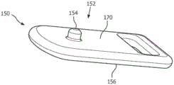
图5B是图3A和图3B的互连组件的凸出式互连构件的轴测图;5B is an isometric view of a male interconnect member of the interconnect assembly of FIGS. 3A and 3B;
图6是图3A和图3B的互连组件的简化截面视图,其中示出另一凹入式互连构件和另一凸出式互连构件;6 is a simplified cross-sectional view of the interconnect assembly of FIGS. 3A and 3B showing another female interconnect member and another male interconnect member;
图7是根据所公开构思的替代性的非限制性实施例的另一互连组件的简化视图;和7 is a simplified view of another interconnect assembly according to an alternative non-limiting embodiment of the disclosed concept; and
图8是根据所公开构思的替代性的非限制性实施例的又一互连组件的简化视图。8 is a simplified view of yet another interconnect assembly in accordance with an alternative non-limiting embodiment of the disclosed concept.
具体实施方式Detailed ways
除非本文中明确地记载,否则用在本文中的方向性短语,例如但不限于,顶、底、左、右、上、下、前、后以及它们的派生词,涉及在图中所示出的元件的方位,且并不是对权利要求的限制。Directional phrases used herein, such as, but not limited to, top, bottom, left, right, top, bottom, front, back, and their derivatives, refer to those shown in the figures unless explicitly stated otherwise herein. The orientation of the elements is not intended to limit the claims.
如本文所采用的,两个或更多个部分或部件“连接”或“联接”在一起的语句是指所述部分直接地或通过一个或多个中间部分或部件连接或一起操作。如本文所使用的,两个或更多个部分或部件彼此“接合”的语句是指所述部分直接地或通过一个或多个中间部分或部件彼此施加力。如本文所使用的,术语“数目”是指一个或大于一的整数(即,多个)。As used herein, the statement that two or more parts or components are "connected" or "coupled" together means that the parts are connected or operate together, either directly or through one or more intermediate parts or components. As used herein, the statement that two or more parts or components "engage" each other means that the parts exert a force on each other, either directly or through one or more intermediate parts or components. As used herein, the term "number" refers to one or an integer greater than one (ie, a plurality).
图1示出了根据所公开构思的非限制性实施例的支撑组件2。支撑组件 2包括保持构件(例如但不限于,面罩框架4)和被构造成可移除地连接到面罩框架4的条带构件(例如但不限于,头架条带6,在虚线图中以简化形式示出)。支撑组件2可以(例如但不限于)在使用患者界面装置(未示出) 的压力支持疗法期间固定到患者的头部。如下文将更详细地论述的,支撑组件2进一步包括快速并且容易地允许面罩框架4可移除地连接到头架条带6的互连组件100(在图1中部分地示出)。Figure 1 shows a support assembly 2 according to a non-limiting embodiment of the disclosed concept. The support assembly 2 includes a retention member (such as, but not limited to, the mask frame 4) and a strap member (such as, but not limited to, the
互连组件100包括多个凹入式互连构件(在图1中示出并且指示了一个凹入式互连构件110,也可参见图6中的凹入式互连构件210)和多个凸出式互连构件(在图1中示出并且指示了一个凸出式互连构件150,也可参见图6中的凸出式互连构件250)。为了节约公开内容,在本文中将详细描述凹入式互连构件110和凸出式互连构件150,但是应当了解,凹入式互连构件210(图6)和凸出式互连构件250(图6)以实质上相同的方式用于支撑组件2,如下文将论述的。
面罩框架4具有位于患者鼻子附近的中心位置8和在相反方向上从中心位置8延伸的一对Y形臂部分10、12。臂部分10、12各自具有一对相应的端部部分(仅指示了端部部分11、13)。如图2A和图2B中所示,端部部分11具有多个通孔(示出并且指示了两个通孔16、18)。凹入式互连构件110延伸穿过通孔16、18,以便有利地将头架条带6(图1)连接到面罩框架4。The
参照图3A和图3B,凹入式互连构件110可移除地连接到凸出式互连构件150。更具体来说,并且参照图3B,凹入式互连构件110包括具有孔隙114的主体构件112,并且凸出式互连构件150包括具有圆柱形的突出部 154的主体构件152。当突出部154设置在孔隙114内时,凹入式互连构件 110被磁性地吸引到凸出式互连构件150,从而将主体构件112可移除地连接到主体构件152。Referring to FIGS. 3A and 3B , the
如图4A和图4B所示,主体构件112包括多个容纳部分120、130。容纳部分120、130可以通过本领域已知的任何合适的机制(例如但不限于,超声波焊接或胶合在一起)联接。容纳部分120、130各自具有相应的突出唇缘122、132和相应的柱124、126、134、136。柱124、126从突出唇缘 122朝向突出唇缘132延伸,柱134、136从突出唇缘132朝向突出唇缘122 延伸。另外,柱124、126各自具有相应的开口125、127。在操作中,柱 124、126、134、136中的每一个延伸穿过通孔16、18(图2A和2B)中的对应一个,并且柱134、136延伸到开口125、127中,以便有利地将主体构件112连接到面罩框架4。以这种方式,突出唇缘122、132位于面罩框架4的相反侧上,以提供相对牢固的连接。As shown in FIGS. 4A and 4B , the
另外,容纳部分120具有环形接收部分128,并且容纳部分130包括延伸到接收部分128中的环形凸缘138,以便进一步提供在容纳部分120、130 之间的牢固连接。如所看到的,容纳部分120、130各自具有相应的凹部121、 131。凹入式互连构件110进一步包括联接到主体构件112并具有与孔隙114 对准的通孔117的盘形磁体116。磁体116位于凹部121、131中的每一个内并且相对于接收部分128和凸缘138而言是在内部。Additionally, the receiving
图5A示出了凸出式互连构件150的部分的分解视图,并且图5B示出了凸出式互连构件150。优选地,凸出式互连构件150通过包覆注射成型工艺制成。例如但不限于,第一模制部分156通过注射成型工艺制成,盘形磁体160放置在第一模制部分156上,然后第二模制部分170优选地被模制在第一模制部分156和磁体160中的每一个上。然而,通过将物体(即,磁体160)嵌入主体构件(未示出)内的任何合适的替代性已知方法来制造凸出式互连构件(未示出)(例如但不限于,以与凹入式互连构件110类似的方式利用位于中间的磁体160将两个分开的半部粘附在一起)在所公开的构思的范围内。FIG. 5A shows an exploded view of a portion of
继续参照图5A,磁体160具有通孔161,并且突出部154包括设置在第一模制部分156中的X形细长主体158。另外,第一模制部分156具有凹部157。在组装期间,磁体160通过被放置到凹部157中而联接到主体构件152,其中细长主体158延伸穿过通孔161。通过采用X形细长主体158,当第二模制部分170被模制在第一模制部分156和磁体160上时,磁体160能够有利地被良好地保持在第一模制部分156上。然而,应当了解,第一模制部分(未示出)可以具有任何合适的替代形状和/或构造,以便在成型工艺的第二阶段期间完成保持磁体160的期望功能。With continued reference to FIG. 5A , the
第一模制部分156进一步具有相反的端部部分162、164。端部部分162 连接到头架条带6(图1)。位于端部部分164附近的是多个稳定化突出部 (示出并且指示了两个稳定化突出部166、168)。当第二模制部分170被模制在第一模制部分156和磁体160上时,稳定化突出部166、168有利地将第一模制部分156保持在相关联的模具(未示出)内。The first molded
图6示出了互连组件100的截面视图。如所看到的,互连组件100包括凹入式互连构件110和凸出式互连构件150,并且进一步包括相反的凹入式互连构件210和相反的凸出式互连构件250(其中类似的附图标记指示类似的特征)。应当理解,凹入式互连构件210和凸出式互连构件250以与凹入式互连构件110和凸出式互连构件150实质上相同的方式被构造成并且连接到支撑组件2。更精确地,凹入式互连构件210和凸出式互连构件250 将端部部分13(图1)连接到头架条带6(图1)。FIG. 6 shows a cross-sectional view of
再次参照图1到图2B,端部部分11、13各自包括相应的凹入接收部分 14、15。通过具有凹入接收部分14、15,互连组件100有利地在使用期间在患者的面部上施加较小的压力。换句话说,当凹入式互连构件110、210 连接到相应的凹入接收部分14、15时,与没有凹入接收部分14、15时相比,凹入式互连构件110、210从相应的端部部分11、13朝向患者面部突出更小的距离。这导致对患者来说明显更舒适的配合。Referring again to Figures 1 to 2B, the
如图6中所示,磁体116大致覆盖并且磁性地吸引到磁体160。更具体地,磁体116具有北极118和南极119。磁体160具有北极163和南极165。如所示出,北极118位于南极119与磁体160之间。此外,北极118和南极 165彼此面对并且彼此磁性地吸引。换句话说,当突出部154设置在孔隙 114中时,磁体116、160被彼此吸引并且有利地使得主体构件112、152能够可移除地彼此连接。以这种方式,当患者期望将主体构件112、152彼此连接并且因此将面罩框架4(图1)的端部部分11连接到头架条带6(图1) 时,患者仅需要将突出部154插入于孔隙114中。在这种构造中,磁体116、 160将被适当地定位以彼此吸引。类似地,当患者期望将主体构件112与主体构件152断开连接时,患者仅需要施加大于磁体116、160之间的磁力的机械力。因此,互连组件100提供了将面罩框架4(图1)连接到头架条带 6(图1)和将面罩框架4(图1)从头架条带6(图1)断开连接明显更容易的机构。As shown in FIG. 6 ,
同样地,凹入式互连构件210包括盘形磁体216,并且凸出式互连构件 250包括盘形磁体260。磁体216具有北极218和南极219,并且磁体260 具有北极263和南极265。如所示出,南极219位于北极218与磁体260之间。此外,南极219和北极263彼此面对并且彼此磁性地吸引。另外,凹入式互连构件210具有孔隙214,并且凸出式互连构件包括被构造成设置在孔隙214中的突出部254。以与凹入式互连构件110和凸出式互连构件150 类似的方式,当突出部254设置在孔隙214中时,磁体216、260被彼此吸引并且有利地使相应的主体构件212、252可移除地彼此连接,因此将端部部分13(图1到图2B)连接到头架条带6(图1)。因此,应当理解,与凹入式互连构件110和凸出式互连构件150相关联的优点同样适用于凹入式互连构件210和凸出式互连构件250。Likewise,
另外,凹入式互连构件110、210和凸出式互连构件150、250有利地具有反转的极性。具体地,北极118设置在凹入式互连构件110的左侧(例如,相对于图6中所示方位中的南极119)上,并且北极163设置在凸出式互连构件150的左侧(例如,相对于图6中所示方位中的南极165)上。相比之下,北极218设置在凹入式互连构件210的右侧(例如,相对于图6 中所示方位中的南极219)上,并且北极263设置在凸出式互连构件250的右侧(例如,相对于图6中所示方位中的南极265)上。以这种方式,当患者期望使面罩框架4(图1)反转时,凸出式互连构件150、250无需与头架条带6(图1)断开连接。更精确地,因为凹入式互连构件具有反转的极性,所以当面罩框架4(图1)反转(未示出)时,凹入式互连构件110将覆盖并磁性地吸引到凸出式互连构件250,并且凹入式互连构件210将覆盖并且被磁性地吸引到凸出式互连构件150。这有利地导致更少的时间来使面罩框架4(图1)与头架6(图1)断开连接和使面罩框架4(图1)重新连接到头架6(图1)。通过具有反转的极性,凸出式互连构件150、250仅需要具有一个相应的突出部154、254,这与在每一侧上具有突出部(未示出) 以适应相应的凹入式互连构件110、210的极性改变相反。除了美学上的改进之外,这还有利地消除了外突出部(未示出)对患者造成任何不适的可能性。Additionally, the
图7示出了可以实施为具有支撑组件2以代替互连组件100的互连组件300的简化视图。如所看到的,互连组件300包括凹入式互连构件310 和凸出式互连构件350。每一个互连构件310、350包括联接到相应的磁体361 、360的相应的主体构件312、352。此外,凹入式互连构件310具有限定孔隙314的接收部分315,并且凸出式互连构件350包括突出部(例如但不限于,钩子354)。当钩子354设置在孔隙314中时,磁体361 、360被彼此吸引,从而将主体构件312可移除地连接到主体构件352。另外,接收部分315的形状大致类似于钩子354。因此,除了将主体构件312、352彼此连接的磁力之外,钩子354还提供额外的保持力以防止主体构件352在使用期间与主体构件312断开连接。FIG. 7 shows a simplified view of an
图8示出了大体上类似于图6的互连组件100的互连组件400的截面视图。在这个实施例中,互连组件400包括凹入式互连构件410和凸出式互连构件450。凸出式互连构件450包括具有北极463和南极465的磁体 460、在其一侧上的第一柱或突出部452和在其相反的第二侧上的第二柱或突出部454。凹入式互连构件410包括具有北极417和南极419的磁体416 和孔隙414,所述孔隙被确定尺寸和构造成接收第一突出部或第二突出部。FIG. 8 shows a cross-sectional view of an
互连组件400的这种构造允许凸出式互连构件450从一侧翻转到另一侧,以使得第一突出部452或第二突出部454能够接合孔隙414。简言之,凸出式互连构件450是实际上可反转的,从而允许任一侧暴露。凹入式互连构件410包括患者接触表面420,该患者接触表面可以以适于接触患者的任何方式(例如,扁平的、平坦的、光滑的、垫衬的和/或波状外形的(contoured))形成。This configuration of
因此,应当理解,所公开的构思提供了改进的(例如但不限于,更容易组装和拆卸)互连组件100、300和包括上述互连组件的支撑组件2,除其它益处外,支撑组件2采用磁体116、160、216、260、361 、360以快速并且容易地允许面罩框架4可移除地连接到头架条带6。Accordingly, it should be appreciated that the disclosed concepts provide improved (eg, but not limited to, easier assembly and disassembly)
另外,尽管已经与支撑组件2相关联地公开了互连组件100、300,但是其它组件(例如但不限于,书包、钱包或其它类似的组件(未示出))采用的互连组件100、300或类似的合适的替代性互连组件(未示出)在所公开的构思的范围内。Additionally, although the
虽然已经详细描述了所公开的构思的具体实施例,但是本领域技术人员应理解,根据本公开内容的整体教导,可以开发出针对那些细节的各种修改和替代方案。因此,所公开的具体布置结构仅仅是例示性的,并且对于所公开构思的范围来说不是限制性的,所述范围应当由所附权利要求及其任何和所有等同方案的整个宽度给定。Although specific embodiments of the disclosed concepts have been described in detail, it will be understood by those skilled in the art that various modifications and alternatives to those details may be developed in light of the overall teachings of this disclosure. Therefore, the specific arrangements disclosed are merely exemplary, and are not limiting as to the scope of the disclosed concepts, which should be given the full breadth of the appended claims and any and all equivalents thereof.
Claims (10)
Applications Claiming Priority (3)
| Application Number | Priority Date | Filing Date | Title |
|---|---|---|---|
| US201462072569P | 2014-10-30 | 2014-10-30 | |
| US62/072,569 | 2014-10-30 | ||
| PCT/IB2015/057938 WO2016067152A1 (en) | 2014-10-30 | 2015-10-15 | Interconnect assembly and support assembly including same |
Publications (2)
| Publication Number | Publication Date |
|---|---|
| CN107106803A CN107106803A (en) | 2017-08-29 |
| CN107106803B true CN107106803B (en) | 2020-11-06 |
Family
ID=54477032
Family Applications (1)
| Application Number | Title | Priority Date | Filing Date |
|---|---|---|---|
| CN201580058129.0A Active CN107106803B (en) | 2014-10-30 | 2015-10-15 | Interconnect assembly and support assembly including the same |
Country Status (5)
| Country | Link |
|---|---|
| US (1) | US10842965B2 (en) |
| EP (2) | EP3363488B1 (en) |
| JP (1) | JP6739429B2 (en) |
| CN (1) | CN107106803B (en) |
| WO (1) | WO2016067152A1 (en) |
Families Citing this family (9)
| Publication number | Priority date | Publication date | Assignee | Title |
|---|---|---|---|---|
| JP7171606B2 (en) * | 2017-03-28 | 2022-11-15 | コーニンクレッカ フィリップス エヌ ヴェ | Valve device for full face mask |
| CN109276787B (en) * | 2017-07-21 | 2021-05-28 | 深圳市美好创亿医疗科技股份有限公司 | Fixing device and mask with same |
| EP3773846B1 (en) | 2018-03-29 | 2023-11-29 | ResMed Pty Ltd | Conduit with magnetic connector |
| US11554236B2 (en) * | 2018-12-24 | 2023-01-17 | Koninklijke Philips N.V. | Patient interface device having magnetic coupling features |
| US20220031990A1 (en) * | 2020-07-29 | 2022-02-03 | ResMed Asia Pte Ltd | Patient interface system and components therefor |
| US12465711B2 (en) * | 2020-12-21 | 2025-11-11 | Koninklijke Philips N.V. | Mask with quick release frame and headgear |
| KR102475624B1 (en) * | 2021-07-19 | 2022-12-08 | 엘지전자 주식회사 | Mask apparatus |
| KR102498505B1 (en) * | 2021-07-19 | 2023-02-10 | 엘지전자 주식회사 | Mask apparatus |
| USD1043965S1 (en) * | 2023-08-10 | 2024-09-24 | Dcstar Inc | Frame |
Citations (4)
| Publication number | Priority date | Publication date | Assignee | Title |
|---|---|---|---|---|
| CN101229410A (en) * | 2002-04-23 | 2008-07-30 | 雷斯梅德有限公司 | Ergonomic and adjustable respiratory mask assembly with headgear assembly |
| CN101389369A (en) * | 2004-06-16 | 2009-03-18 | 雷斯梅德有限公司 | Cushion for respiratory mask assembly |
| WO2014025267A1 (en) * | 2012-08-08 | 2014-02-13 | Fisher & Paykel Healthcare Limited | Headgear for patient interface |
| US20140283826A1 (en) * | 2013-03-19 | 2014-09-25 | Curtis Murray | Quick Release Magnetic Clasp for Continuous Positive Airway Pressure Interface Devices |
Family Cites Families (27)
| Publication number | Priority date | Publication date | Assignee | Title |
|---|---|---|---|---|
| US3032847A (en) | 1961-02-06 | 1962-05-08 | Weiswurm Konrad | Quick release mechanism for oxygen mask |
| CH608351A5 (en) * | 1976-06-16 | 1979-01-15 | Stephan Marbacher | |
| DE3736254A1 (en) * | 1987-10-27 | 1989-05-11 | Uhli Hinderberger | Fastener for clothing |
| DE4224476C2 (en) * | 1992-07-24 | 1995-10-26 | Optrel Ag | Device for protecting the human head against external influences |
| US5630258A (en) * | 1995-08-07 | 1997-05-20 | Schneider; John R. | Magnetic buckle |
| US5983464A (en) * | 1997-12-16 | 1999-11-16 | Bauer; Irving | Magnetic fastener |
| IT1297007B1 (en) * | 1997-12-22 | 1999-08-03 | Sama S P A | MAGNETIC CLOSURE WITH MUTUAL CONNECTION FOR BAGS, BACKPACKS, CLOTHING AND SIMILAR |
| US5974634A (en) * | 1998-09-08 | 1999-11-02 | Eisenpresser; Kenneth | Decorative multi-use magnetic buttons |
| JP2002191410A (en) * | 2000-12-26 | 2002-07-09 | Yamato Shoji Nire:Kk | Clasp |
| US8042542B2 (en) * | 2002-04-23 | 2011-10-25 | Resmed Limited | Respiratory mask assembly with magnetic coupling to headgear assembly |
| AUPS192602A0 (en) | 2002-04-23 | 2002-05-30 | Resmed Limited | Nasal mask |
| US7743767B2 (en) * | 2002-04-23 | 2010-06-29 | Resmed Limited | Ergonomic and adjustable respiratory mask assembly with frame |
| NZ604214A (en) * | 2002-11-08 | 2014-06-27 | Resmed Ltd | Headgear assembly for a respiratory mask assembly |
| US20060174892A1 (en) | 2005-01-05 | 2006-08-10 | Steven Leksutin | Method and apparatus for magnetically connecting a head gear to an air mask |
| CN101657120B (en) * | 2006-07-12 | 2013-03-27 | 菲德洛克有限责任公司 | Mechanic-magnetic connecting structure |
| NZ569226A (en) * | 2007-06-22 | 2010-02-26 | Resmed Ltd | Flexible forehead support |
| US7681256B2 (en) | 2008-05-20 | 2010-03-23 | Cedar Ridge Research, Llc. | Correlated magnetic mask and method for using the correlated magnetic mask |
| US8210572B2 (en) | 2008-05-30 | 2012-07-03 | Hana Consulting, Inc. | Magnetic coupling device and method |
| US20100257898A1 (en) * | 2009-04-08 | 2010-10-14 | Aleshia Michelle Bonilla | Magnetic Jewelry Clasp and Interchangeable Pendant System |
| DE202010010300U1 (en) * | 2009-08-24 | 2010-10-21 | Fidlock Gmbh | Mechanical lock with a locking device |
| JP2012147980A (en) * | 2011-01-20 | 2012-08-09 | Morito Co Ltd | Buckle made with magnet |
| PL67376Y1 (en) | 2011-11-08 | 2014-09-30 | Select Spółka Z Ograniczoną Odpowiedzialnością | Anti-chipping face-guard |
| BR112014030323A2 (en) | 2012-06-07 | 2017-06-27 | Koninklijke Philips Nv | mask assembly for use in a system that supplies a pediatric patient airway treatment gas flow, a pediatric patient airway treatment gas supply system, kit |
| RU2650074C2 (en) | 2012-09-21 | 2018-04-06 | Конинклейке Филипс Н.В. | Respiratory mask with patch retained by magnetic action |
| EP2833754B1 (en) * | 2012-12-14 | 2016-04-27 | Fidlock GmbH | Closure device for detachably connecting two parts |
| EP3967352B1 (en) * | 2013-01-16 | 2026-01-07 | ResMed Pty Ltd | Patient interface |
| EP3348299B1 (en) * | 2013-01-18 | 2025-04-02 | ResMed Pty Ltd | Headgear system and patient interface |
-
2015
- 2015-10-15 CN CN201580058129.0A patent/CN107106803B/en active Active
- 2015-10-15 EP EP18152095.8A patent/EP3363488B1/en active Active
- 2015-10-15 WO PCT/IB2015/057938 patent/WO2016067152A1/en not_active Ceased
- 2015-10-15 US US15/520,857 patent/US10842965B2/en active Active
- 2015-10-15 EP EP15790675.1A patent/EP3212265A1/en not_active Withdrawn
- 2015-10-15 JP JP2017523352A patent/JP6739429B2/en active Active
Patent Citations (4)
| Publication number | Priority date | Publication date | Assignee | Title |
|---|---|---|---|---|
| CN101229410A (en) * | 2002-04-23 | 2008-07-30 | 雷斯梅德有限公司 | Ergonomic and adjustable respiratory mask assembly with headgear assembly |
| CN101389369A (en) * | 2004-06-16 | 2009-03-18 | 雷斯梅德有限公司 | Cushion for respiratory mask assembly |
| WO2014025267A1 (en) * | 2012-08-08 | 2014-02-13 | Fisher & Paykel Healthcare Limited | Headgear for patient interface |
| US20140283826A1 (en) * | 2013-03-19 | 2014-09-25 | Curtis Murray | Quick Release Magnetic Clasp for Continuous Positive Airway Pressure Interface Devices |
Also Published As
| Publication number | Publication date |
|---|---|
| CN107106803A (en) | 2017-08-29 |
| EP3363488A2 (en) | 2018-08-22 |
| EP3212265A1 (en) | 2017-09-06 |
| US20170333660A1 (en) | 2017-11-23 |
| EP3363488B1 (en) | 2022-05-25 |
| JP6739429B2 (en) | 2020-08-12 |
| JP2017533030A (en) | 2017-11-09 |
| EP3363488A3 (en) | 2018-11-14 |
| US10842965B2 (en) | 2020-11-24 |
| WO2016067152A1 (en) | 2016-05-06 |
Similar Documents
| Publication | Publication Date | Title |
|---|---|---|
| CN107106803B (en) | Interconnect assembly and support assembly including the same | |
| US20240216634A1 (en) | Respiratory mask having a magnetically supported cushion | |
| US11660414B2 (en) | Patient interface device and retention assembly therefor | |
| JP6720186B2 (en) | Patient interface device | |
| JP2014532502A (en) | Patient interface with headgear post to clip or strap | |
| JP2014532500A (en) | Modular patient interface device with chamber and nasal pillow assembly | |
| JP2022512120A (en) | Patient interface device with magnetic coupling mechanism | |
| CN109310841B (en) | Magnetically assisted seal arrangement for patient interface device | |
| JP2013517036A (en) | Replaceable nose pillow | |
| US20130220328A1 (en) | Gas delivery conduit management system | |
| CN103533981A (en) | Low profile mask attachment element | |
| EP3522967B1 (en) | Magnetic anti-crush feature for conduit | |
| US10016572B2 (en) | Pivoting quick release for a patient interface device |
Legal Events
| Date | Code | Title | Description |
|---|---|---|---|
| PB01 | Publication | ||
| PB01 | Publication | ||
| SE01 | Entry into force of request for substantive examination | ||
| SE01 | Entry into force of request for substantive examination | ||
| GR01 | Patent grant | ||
| GR01 | Patent grant |