CN107084029B - Urea mixer - Google Patents
Urea mixer Download PDFInfo
- Publication number
- CN107084029B CN107084029B CN201710070410.7A CN201710070410A CN107084029B CN 107084029 B CN107084029 B CN 107084029B CN 201710070410 A CN201710070410 A CN 201710070410A CN 107084029 B CN107084029 B CN 107084029B
- Authority
- CN
- China
- Prior art keywords
- mixer
- exhaust
- downstream
- urea
- upstream
- Prior art date
- Legal status (The legal status is an assumption and is not a legal conclusion. Google has not performed a legal analysis and makes no representation as to the accuracy of the status listed.)
- Expired - Fee Related
Links
Images


Classifications
-
- F—MECHANICAL ENGINEERING; LIGHTING; HEATING; WEAPONS; BLASTING
- F01—MACHINES OR ENGINES IN GENERAL; ENGINE PLANTS IN GENERAL; STEAM ENGINES
- F01N—GAS-FLOW SILENCERS OR EXHAUST APPARATUS FOR MACHINES OR ENGINES IN GENERAL; GAS-FLOW SILENCERS OR EXHAUST APPARATUS FOR INTERNAL-COMBUSTION ENGINES
- F01N3/00—Exhaust or silencing apparatus having means for purifying, rendering innocuous, or otherwise treating exhaust
- F01N3/08—Exhaust or silencing apparatus having means for purifying, rendering innocuous, or otherwise treating exhaust for rendering innocuous
- F01N3/10—Exhaust or silencing apparatus having means for purifying, rendering innocuous, or otherwise treating exhaust for rendering innocuous by thermal or catalytic conversion of noxious components of exhaust
- F01N3/24—Exhaust or silencing apparatus having means for purifying, rendering innocuous, or otherwise treating exhaust for rendering innocuous by thermal or catalytic conversion of noxious components of exhaust characterised by constructional aspects of converting apparatus
- F01N3/28—Construction of catalytic reactors
- F01N3/2892—Exhaust flow directors or the like, e.g. upstream of catalytic device
-
- F—MECHANICAL ENGINEERING; LIGHTING; HEATING; WEAPONS; BLASTING
- F01—MACHINES OR ENGINES IN GENERAL; ENGINE PLANTS IN GENERAL; STEAM ENGINES
- F01N—GAS-FLOW SILENCERS OR EXHAUST APPARATUS FOR MACHINES OR ENGINES IN GENERAL; GAS-FLOW SILENCERS OR EXHAUST APPARATUS FOR INTERNAL-COMBUSTION ENGINES
- F01N13/00—Exhaust or silencing apparatus characterised by constructional features
- F01N13/08—Other arrangements or adaptations of exhaust conduits
- F01N13/082—Other arrangements or adaptations of exhaust conduits of tailpipe, e.g. with means for mixing air with exhaust for exhaust cooling, dilution or evacuation
-
- F—MECHANICAL ENGINEERING; LIGHTING; HEATING; WEAPONS; BLASTING
- F01—MACHINES OR ENGINES IN GENERAL; ENGINE PLANTS IN GENERAL; STEAM ENGINES
- F01N—GAS-FLOW SILENCERS OR EXHAUST APPARATUS FOR MACHINES OR ENGINES IN GENERAL; GAS-FLOW SILENCERS OR EXHAUST APPARATUS FOR INTERNAL-COMBUSTION ENGINES
- F01N3/00—Exhaust or silencing apparatus having means for purifying, rendering innocuous, or otherwise treating exhaust
- F01N3/08—Exhaust or silencing apparatus having means for purifying, rendering innocuous, or otherwise treating exhaust for rendering innocuous
- F01N3/10—Exhaust or silencing apparatus having means for purifying, rendering innocuous, or otherwise treating exhaust for rendering innocuous by thermal or catalytic conversion of noxious components of exhaust
- F01N3/18—Exhaust or silencing apparatus having means for purifying, rendering innocuous, or otherwise treating exhaust for rendering innocuous by thermal or catalytic conversion of noxious components of exhaust characterised by methods of operation; Control
- F01N3/20—Exhaust or silencing apparatus having means for purifying, rendering innocuous, or otherwise treating exhaust for rendering innocuous by thermal or catalytic conversion of noxious components of exhaust characterised by methods of operation; Control specially adapted for catalytic conversion
- F01N3/206—Adding periodically or continuously substances to exhaust gases for promoting purification, e.g. catalytic material in liquid form, NOx reducing agents
- F01N3/2066—Selective catalytic reduction [SCR]
-
- F—MECHANICAL ENGINEERING; LIGHTING; HEATING; WEAPONS; BLASTING
- F01—MACHINES OR ENGINES IN GENERAL; ENGINE PLANTS IN GENERAL; STEAM ENGINES
- F01N—GAS-FLOW SILENCERS OR EXHAUST APPARATUS FOR MACHINES OR ENGINES IN GENERAL; GAS-FLOW SILENCERS OR EXHAUST APPARATUS FOR INTERNAL-COMBUSTION ENGINES
- F01N3/00—Exhaust or silencing apparatus having means for purifying, rendering innocuous, or otherwise treating exhaust
- F01N3/08—Exhaust or silencing apparatus having means for purifying, rendering innocuous, or otherwise treating exhaust for rendering innocuous
- F01N3/10—Exhaust or silencing apparatus having means for purifying, rendering innocuous, or otherwise treating exhaust for rendering innocuous by thermal or catalytic conversion of noxious components of exhaust
- F01N3/18—Exhaust or silencing apparatus having means for purifying, rendering innocuous, or otherwise treating exhaust for rendering innocuous by thermal or catalytic conversion of noxious components of exhaust characterised by methods of operation; Control
- F01N3/20—Exhaust or silencing apparatus having means for purifying, rendering innocuous, or otherwise treating exhaust for rendering innocuous by thermal or catalytic conversion of noxious components of exhaust characterised by methods of operation; Control specially adapted for catalytic conversion
- F01N3/206—Adding periodically or continuously substances to exhaust gases for promoting purification, e.g. catalytic material in liquid form, NOx reducing agents
- F01N3/208—Control of selective catalytic reduction [SCR], e.g. by adjusting the dosing of reducing agent
-
- F—MECHANICAL ENGINEERING; LIGHTING; HEATING; WEAPONS; BLASTING
- F01—MACHINES OR ENGINES IN GENERAL; ENGINE PLANTS IN GENERAL; STEAM ENGINES
- F01N—GAS-FLOW SILENCERS OR EXHAUST APPARATUS FOR MACHINES OR ENGINES IN GENERAL; GAS-FLOW SILENCERS OR EXHAUST APPARATUS FOR INTERNAL-COMBUSTION ENGINES
- F01N9/00—Electrical control of exhaust gas treating apparatus
-
- F—MECHANICAL ENGINEERING; LIGHTING; HEATING; WEAPONS; BLASTING
- F01—MACHINES OR ENGINES IN GENERAL; ENGINE PLANTS IN GENERAL; STEAM ENGINES
- F01N—GAS-FLOW SILENCERS OR EXHAUST APPARATUS FOR MACHINES OR ENGINES IN GENERAL; GAS-FLOW SILENCERS OR EXHAUST APPARATUS FOR INTERNAL-COMBUSTION ENGINES
- F01N2240/00—Combination or association of two or more different exhaust treating devices, or of at least one such device with an auxiliary device, not covered by indexing codes F01N2230/00 or F01N2250/00, one of the devices being
- F01N2240/20—Combination or association of two or more different exhaust treating devices, or of at least one such device with an auxiliary device, not covered by indexing codes F01N2230/00 or F01N2250/00, one of the devices being a flow director or deflector
-
- F—MECHANICAL ENGINEERING; LIGHTING; HEATING; WEAPONS; BLASTING
- F01—MACHINES OR ENGINES IN GENERAL; ENGINE PLANTS IN GENERAL; STEAM ENGINES
- F01N—GAS-FLOW SILENCERS OR EXHAUST APPARATUS FOR MACHINES OR ENGINES IN GENERAL; GAS-FLOW SILENCERS OR EXHAUST APPARATUS FOR INTERNAL-COMBUSTION ENGINES
- F01N2470/00—Structure or shape of exhaust gas passages, pipes or tubes
- F01N2470/02—Tubes being perforated
-
- F—MECHANICAL ENGINEERING; LIGHTING; HEATING; WEAPONS; BLASTING
- F01—MACHINES OR ENGINES IN GENERAL; ENGINE PLANTS IN GENERAL; STEAM ENGINES
- F01N—GAS-FLOW SILENCERS OR EXHAUST APPARATUS FOR MACHINES OR ENGINES IN GENERAL; GAS-FLOW SILENCERS OR EXHAUST APPARATUS FOR INTERNAL-COMBUSTION ENGINES
- F01N2470/00—Structure or shape of exhaust gas passages, pipes or tubes
- F01N2470/30—Tubes with restrictions, i.e. venturi or the like, e.g. for sucking air or measuring mass flow
-
- F—MECHANICAL ENGINEERING; LIGHTING; HEATING; WEAPONS; BLASTING
- F01—MACHINES OR ENGINES IN GENERAL; ENGINE PLANTS IN GENERAL; STEAM ENGINES
- F01N—GAS-FLOW SILENCERS OR EXHAUST APPARATUS FOR MACHINES OR ENGINES IN GENERAL; GAS-FLOW SILENCERS OR EXHAUST APPARATUS FOR INTERNAL-COMBUSTION ENGINES
- F01N2610/00—Adding substances to exhaust gases
- F01N2610/02—Adding substances to exhaust gases the substance being ammonia or urea
-
- F—MECHANICAL ENGINEERING; LIGHTING; HEATING; WEAPONS; BLASTING
- F01—MACHINES OR ENGINES IN GENERAL; ENGINE PLANTS IN GENERAL; STEAM ENGINES
- F01N—GAS-FLOW SILENCERS OR EXHAUST APPARATUS FOR MACHINES OR ENGINES IN GENERAL; GAS-FLOW SILENCERS OR EXHAUST APPARATUS FOR INTERNAL-COMBUSTION ENGINES
- F01N2610/00—Adding substances to exhaust gases
- F01N2610/14—Arrangements for the supply of substances, e.g. conduits
- F01N2610/1453—Sprayers or atomisers; Arrangement thereof in the exhaust apparatus
-
- F—MECHANICAL ENGINEERING; LIGHTING; HEATING; WEAPONS; BLASTING
- F01—MACHINES OR ENGINES IN GENERAL; ENGINE PLANTS IN GENERAL; STEAM ENGINES
- F01N—GAS-FLOW SILENCERS OR EXHAUST APPARATUS FOR MACHINES OR ENGINES IN GENERAL; GAS-FLOW SILENCERS OR EXHAUST APPARATUS FOR INTERNAL-COMBUSTION ENGINES
- F01N2900/00—Details of electrical control or of the monitoring of the exhaust gas treating apparatus
- F01N2900/06—Parameters used for exhaust control or diagnosing
- F01N2900/14—Parameters used for exhaust control or diagnosing said parameters being related to the exhaust gas
- F01N2900/1411—Exhaust gas flow rate, e.g. mass flow rate or volumetric flow rate
-
- Y—GENERAL TAGGING OF NEW TECHNOLOGICAL DEVELOPMENTS; GENERAL TAGGING OF CROSS-SECTIONAL TECHNOLOGIES SPANNING OVER SEVERAL SECTIONS OF THE IPC; TECHNICAL SUBJECTS COVERED BY FORMER USPC CROSS-REFERENCE ART COLLECTIONS [XRACs] AND DIGESTS
- Y02—TECHNOLOGIES OR APPLICATIONS FOR MITIGATION OR ADAPTATION AGAINST CLIMATE CHANGE
- Y02A—TECHNOLOGIES FOR ADAPTATION TO CLIMATE CHANGE
- Y02A50/00—TECHNOLOGIES FOR ADAPTATION TO CLIMATE CHANGE in human health protection, e.g. against extreme weather
- Y02A50/20—Air quality improvement or preservation, e.g. vehicle emission control or emission reduction by using catalytic converters
-
- Y—GENERAL TAGGING OF NEW TECHNOLOGICAL DEVELOPMENTS; GENERAL TAGGING OF CROSS-SECTIONAL TECHNOLOGIES SPANNING OVER SEVERAL SECTIONS OF THE IPC; TECHNICAL SUBJECTS COVERED BY FORMER USPC CROSS-REFERENCE ART COLLECTIONS [XRACs] AND DIGESTS
- Y02—TECHNOLOGIES OR APPLICATIONS FOR MITIGATION OR ADAPTATION AGAINST CLIMATE CHANGE
- Y02T—CLIMATE CHANGE MITIGATION TECHNOLOGIES RELATED TO TRANSPORTATION
- Y02T10/00—Road transport of goods or passengers
- Y02T10/10—Internal combustion engine [ICE] based vehicles
- Y02T10/12—Improving ICE efficiencies
-
- Y—GENERAL TAGGING OF NEW TECHNOLOGICAL DEVELOPMENTS; GENERAL TAGGING OF CROSS-SECTIONAL TECHNOLOGIES SPANNING OVER SEVERAL SECTIONS OF THE IPC; TECHNICAL SUBJECTS COVERED BY FORMER USPC CROSS-REFERENCE ART COLLECTIONS [XRACs] AND DIGESTS
- Y02—TECHNOLOGIES OR APPLICATIONS FOR MITIGATION OR ADAPTATION AGAINST CLIMATE CHANGE
- Y02T—CLIMATE CHANGE MITIGATION TECHNOLOGIES RELATED TO TRANSPORTATION
- Y02T10/00—Road transport of goods or passengers
- Y02T10/10—Internal combustion engine [ICE] based vehicles
- Y02T10/40—Engine management systems
Landscapes
- Engineering & Computer Science (AREA)
- Chemical & Material Sciences (AREA)
- Chemical Kinetics & Catalysis (AREA)
- Combustion & Propulsion (AREA)
- Mechanical Engineering (AREA)
- General Engineering & Computer Science (AREA)
- Health & Medical Sciences (AREA)
- Toxicology (AREA)
- Exhaust Gas After Treatment (AREA)
Abstract
本申请涉及尿素混合器。提供了用于尿素混合器的方法和系统。在一个示例中,尿素混合器可包括被定位成邻近文丘里管通道的喉部的多个出口。
The present application relates to urea mixers. Methods and systems for urea mixers are provided. In one example, the urea mixer may include a plurality of outlets positioned adjacent the throat of the venturi channel.
Description
Technical Field
The present description generally relates to methods and systems for urea mixers.
Background
One technique for the aftertreatment of engine exhaust uses Selective Catalytic Reduction (SCR) to allow certain chemical reactions to occur between NOx and ammonia (NH3) in the exhaust. NH3 is introduced into the engine exhaust system upstream of the SCR catalyst, or is generated in an upstream catalyst, by injecting urea into the exhaust passage. Urea is entropically (entropically) degraded under high temperature conditions to NH 3. SCR promotes a reaction between NH3 and NOx to convert NOx to nitrogen (N2) and water (H2O). However, as recognized by the inventors herein, problems may arise when injecting urea into the exhaust passage. In one example, urea may mix poorly into the exhaust stream (e.g., a first portion of the exhaust stream has a higher concentration of urea than a second portion of the exhaust stream), which may result in poor coating of the SCR and poor reactivity between emissions (e.g., NOx) and the SCR. In addition, excessive mixing and agitation of the urea in the exhaust gas can also cause problems, such as increased deposits.
Attempts to address inadequate mixing have included introducing a mixing device downstream of the urea injector and upstream of the SCR so that the exhaust flow may be more uniform. Other attempts to address urea mixing include static mixing devices. Cho et al in US2013/0104531 shows an exemplary method. Wherein the static mixer is located in the exhaust passage downstream of the outer tube for injecting urea. Exhaust gas flows through the exhaust passage and is combined with the urea injection before flowing through the static mixer.
However, the inventors herein have recognized potential problems with such systems. As one example, the static mixers described above exhibit limited mixing capabilities due to the directionality of the exhaust gas outflow through the mixer, failing to completely mix the laminar exhaust flow. Static mixers in the exhaust path also present manufacturing and packaging limitations. Different exhaust passage geometries require changes in the manufacture of the static mixer to allow the mixer to fit closely within the exhaust passage.
Disclosure of Invention
In one example, the above problem may be solved by a mixer comprising a hollow annular ring having an internal exhaust passage, the ring comprising an inlet on a downstream inner surface and an outlet located along an intersection between an upstream inner surface and the downstream inner surface adjacent a throat (throat) of a venturi passage upstream of an SCR device; and a urea injector positioned to inject into the annulus. In this manner, the outlet may be fluidly coupled to a vacuum created by flowing exhaust gas through the venturi passage.
As one example, the vacuum created by the venturi passage is supplied to an annular chamber created in the space outside the upstream and downstream inner surfaces and within the exhaust passage, wherein the supplied vacuum may draw exhaust gas into the annular chamber through the inlet. The exhaust gas in the annular chamber may mix with urea and/or exhaust gas from different regions of the exhaust passage. The inner ring surface may be shaped to form a venturi and may completely separate the exhaust gas in the central passage from the hollow interior, except for the inlet and outlet. The mixture of exhaust gas and urea flows into the inner central exhaust passage by the generated vacuum, where the mixture may be combined with the exhaust gas without injected reductant. In this way, the entire exhaust flow through the exhaust passage may be more in contact with urea and improve the overall reduction of the SCR device.
It should be appreciated that the summary above is provided to introduce a selection of concepts in a simplified form that are further described in the detailed description. It is not intended to identify key or essential features of the claimed subject matter, the scope of which is defined uniquely by the claims that follow the detailed description. Furthermore, the claimed subject matter is not limited to implementations that solve any disadvantages noted above or in any part of this disclosure.
Drawings
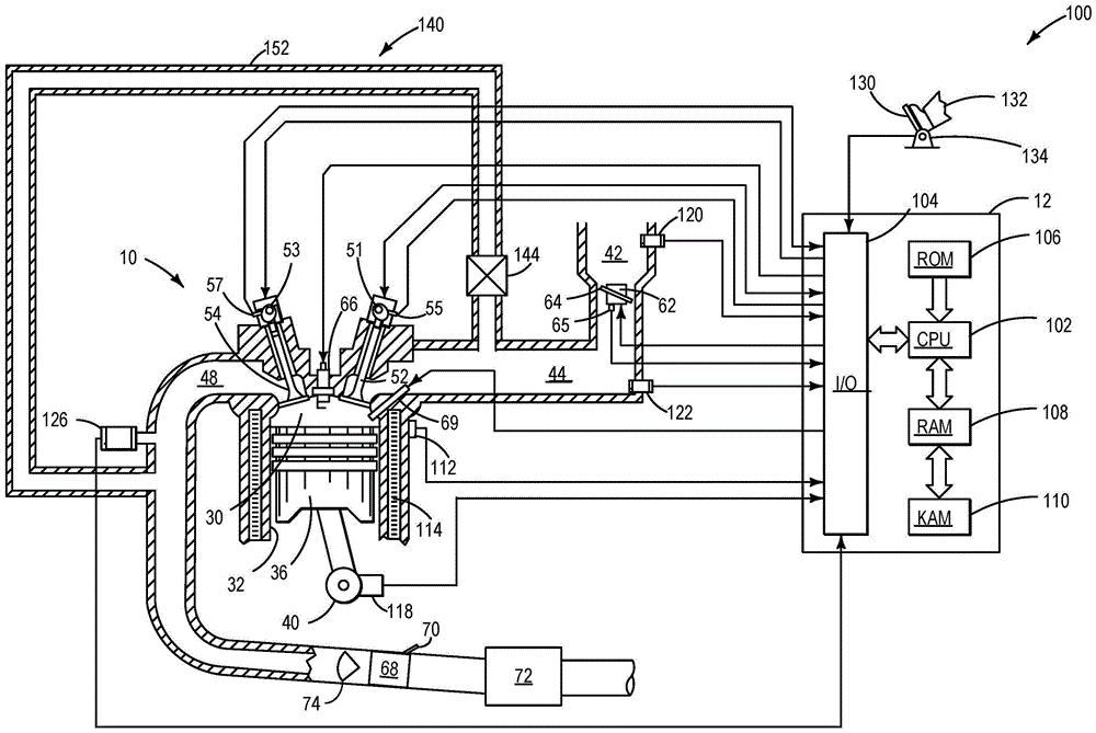
FIG. 1 shows a schematic diagram of an engine having a mixer.
Fig. 2 shows an isometric view of a mixer positioned along the exhaust passage.
Fig. 3 shows a downstream to upstream forward view of the mixer.
FIG. 4 illustrates a cutaway view of a mixer with an exemplary exhaust flow directed through the mixer.
Fig. 2-4 are shown approximately to scale, but other relative dimensions may be used.
Fig. 5 illustrates a method for operating an ejector of a mixer.
Detailed Description
The following description relates to systems and methods for a urea mixer configured to receive urea injection from an injector. The urea mixer may be located upstream of the SCR catalyst, as shown in fig. 1. A venturi device may be located upstream of the urea mixer to further promote urea mixing. The urea mixer is in coplanar contact with the exhaust pipe, wherein the urea mixer protrudes annularly into the exhaust passage, as shown in fig. 2. The urea mixer includes a curved upstream wall and a curved downstream wall, wherein the urea mixer projects annularly from the exhaust pipe into the exhaust passage. The inlet is not aligned with the downstream wall and is located on the downstream wall, as shown in fig. 3. The outlet is located at the intersection between the upstream wall and the downstream wall, as also shown in fig. 3. A side view of the mixer is shown in fig. 4, which shows the extent of the profile on the upstream side and the extent of the profile on the downstream side, and an example flow of exhaust gas through the mixer. A method for operating a urea injector and venturi is shown in fig. 5.
Fig. 2-4 illustrate example configurations with relative positioning of various components. In at least one example, if shown in direct contact with each other, or directly coupled, these elements may be referred to as being in direct contact or directly coupled, respectively. Similarly, elements shown as abutting or adjacent to one another may, at least in one example, abut or be adjacent to one another, respectively. By way of example, components placed in coplanar contact with each other may be referred to as coplanar contacts. As another example, in at least one example, elements that are positioned apart from one another with only space between them and no other components may be referred to as such.
Continuing to FIG. 1, a schematic diagram of one cylinder of multi-cylinder engine 10 in engine system 100, which may be included in a propulsion system of an automobile, is shown. Engine 10 may be controlled at least partially by a control system including controller 12 and by input from a vehicle operator 132 via an input device 130. In this example, the input device 130 includes an accelerator pedal and a pedal position sensor 134 for generating a proportional pedal position signal. Combustion chamber 30 of engine 10 may include a cylinder formed by cylinder walls 32 with a piston 36 positioned therein. Piston 36 may be coupled to crankshaft 40 such that reciprocating motion of the piston is translated into rotational motion of the crankshaft. Crankshaft 40 may be coupled to at least one drive wheel of a vehicle via an intermediate transmission system. Further, a starter motor may be coupled to crankshaft 40 via a flywheel to enable a starting operation of engine 10.
In this example, intake valve 52 and exhaust valve 54 may be controlled via respective cam actuation systems 51 and 53 via cam actuation. Cam actuation systems 51 and 53 may each include one or more cams and may utilize one or more of a cam profile switching system (CPS), a Variable Cam Timing (VCT), a Variable Valve Timing (VVT) and/or a Variable Valve Lift (VVL) system, which may be operated by controller 12 to vary valve operation. The position of intake valve 52 and exhaust valve 54 may be determined by position sensors 55 and 57, respectively. In alternative examples, intake valve 52 and/or exhaust valve 54 may be controlled by electric valve actuation. For example, cylinder 30 may alternatively include an intake valve controlled via electric valve actuation and an exhaust valve controlled via cam actuation including CPS and/or VCT systems.
Spark is provided to combustion chamber 30 via spark plug 66. The ignition system may further include an ignition coil (not shown) for increasing the voltage supplied to the spark plug 66. In other examples, such as diesel, spark plug 66 may be omitted.
Exhaust Gas Recirculation (EGR) system 140 may communicate a desired portion of exhaust gas from exhaust passage 48 to intake manifold 44 via EGR passage 152. The amount of EGR provided to intake manifold 44 may be varied by controller 12 via EGR valve 144. Under some conditions, EGR system 140 may be used to regulate the temperature of the air-fuel mixture within the combustion chamber, thus providing a method of controlling the spark timing during some combustion modes.
The controller 12 is shown in fig. 1 as a microcomputer that includes a microprocessor unit (CPU)102, input/output ports (I/O)104, an electronic storage medium, shown in this particular example as a read only memory chip (ROM)106 (e.g., non-transitory memory), a Random Access Memory (RAM)108, a Keep Alive Memory (KAM)110, and a data bus, for executable programs and calibration values. In addition to those signals previously discussed, controller 12 may receive various signals from sensors coupled to engine 10, including a measure of the Mass Air Flow (MAF) inducted from mass air flow sensor 120; engine Coolant Temperature (ECT) from temperature sensor 112 coupled to cooling sleeve 114; an engine position signal from a Hall effect sensor 118 (or other type) that senses a position of crankshaft 40; throttle position from throttle position sensor 65; and a Manifold Absolute Pressure (MAP) signal from sensor 122. An engine speed signal may be generated by controller 12 based on crankshaft position sensor 118. The manifold pressure signal also provides an indication of vacuum or pressure in intake manifold 44. It is noted that various combinations of the above sensors may be used, such as no MAP sensor and a MAF sensor, or vice versa. During engine operation, engine torque may be inferred from the output of the MAP sensor 122 and engine speed. Furthermore, the sensor, along with the detected engine speed, may be the basis for estimating the charge (including air) inducted into the cylinder. In one example, a crankshaft position sensor 118, which also functions as an engine speed sensor, may produce a predetermined number of equally spaced pulses per revolution of the crankshaft.
Storage medium read-only memory 106 can be programmed with computer readable data representing non-transitory instructions executable by processor 102 to perform the methods described below as well as other variations that are anticipated but not specifically listed.
The controller 12 receives signals from the various sensors of FIG. 1 and, based on the received signals and instructions stored on the controller's memory, employs the various actuators of FIG. 1 to adjust engine operation. For example, adjusting the oxidation state of the SCR may include adjusting an actuator of a urea injector to inject urea to reduce the SCR. For example, adjusting injection into the mixer may include adjusting an actuator of the injector to open an orifice of the injector to inject an amount of fluid into the mixer.
FIG. 2 shows an isometric view of mixer 200 positioned within exhaust pipe 204 along exhaust passage 202. The mixer 200 may be used similarly to the mixer 68 in the embodiment of fig. 1. The mixer 200 is continuous and hollow with an uninterrupted passageway therein for mixing urea with exhaust gases. The mixer 200 may receive exhaust gas via a plurality of inlets and discharge exhaust gas via a plurality of outlets. In the present description, a portion of the exhaust pipe 204 is omitted to expose the mixer 200. The mixer 200 is fixed in the exhaust passage 202, and may not be coupled to a mechanical actuator or an electronic actuator.
Coordinate system 290 is shown to include three axes, an x-axis in a horizontal direction, a y-axis in a vertical direction, and a z-axis in a direction perpendicular to both the x-axis and the y-axis. The central axis 295 of the exhaust pipe 204 is shown by a dashed line. The mixer 200 may be symmetrical about a central axis 295. The general direction of exhaust flow is shown by arrow 298.
The mixer 200 may be a single machined piece. Mixer 200 may be composed of one or more of a ceramic material, a metal alloy, a silicon derivative, or other suitable material capable of withstanding high temperatures while also mitigating friction experienced by the exhaust flow such that exhaust pressure is maintained. Additionally or alternatively, the mixer 200 may include one or more of coatings and materials such that exhaust gas may contact surfaces of the mixer 200 without depositing soot or other exhaust gas constituents on the mixer 200.
The exhaust pipe 204 is tubular and configured to guide exhaust gas through the exhaust passage 202. Mixer 200 is in coplanar contact with the inner circumference of exhaust pipe 204 via outer annular surface 206 in such a way that gas cannot flow between the outer annular surface and exhaust pipe 204. The outer annular surface 206 may be coupled to the exhaust pipe 204 via welding, adhesives, and/or other suitable coupling means that provide a hermetic seal. In some embodiments, the mixer 200 may be forcibly slid into the exhaust passage 202. In this manner, mixer 200 includes an outer circumference that is correspondingly smaller than an inner circumference of exhaust pipe 204 such that the mixer is positioned along exhaust passage 202 while substantially not allowing exhaust gas to flow between the exhaust pipe and outer annular surface 206.
The outer annular surface 206 includes a width equal to the distance between the upstream edge 207 and the downstream edge 208. The circumference of the upstream edge 207 is substantially equal to the circumference of the downstream edge 208. A first inner surface 210 of mixer 200 is located between upstream edge 207 and annular intersection 212. The second inner surface 220 is located between the annular intersection 212 and the downstream edge 208. The first inner surface 210 may be continuous with at least some portion of the second inner surface 220. Thus, the first inner surface 210 is upstream of the second inner surface 220. The first inner surface 210 may be referred to herein as the upstream surface 210, and the second inner surface 220 may be referred to herein as the downstream surface 220.
The upstream and downstream surfaces 210, 220 extend from the outer annular surface 206 and project radially into the exhaust passage 202. A hole (opening) 230 is formed through the protruding surface of the mixer 200 so that the exhaust passage 202 is narrowed by the mixer forming the central exhaust passage. This narrowing of the central exhaust passage may create an internal passage (e.g., throat) of the venturi passage within the exhaust passage, as will be described in more detail below. Upstream surface 210 and downstream surface 220 are radially spaced from central axis 295.
The upstream surface 210 is curved and becomes progressively radially spaced from the central axis 295 in the downstream direction. Downstream surface 220 is curved and becomes increasingly radially spaced from central axis 295 in the downstream direction. As an example, upstream surface 210 may be curved outward and downstream surface 220 may be curved inward, relative to central axis 295. In this manner, the annular intersection 212 at the juncture of the upstream and downstream surfaces 210, 220 is adjacent the narrowest portion of the exhaust passage 202 within the bore 230.
As described above, mixer 200 is hollow, having an annular chamber located inside upstream surface 210, downstream surface 220, and outer annular surface 206. The annular chamber spans the entire 360 of the interior of the mixer 200. The annular chamber is configured to receive exhaust gas through a plurality of inlets, including an upstream inlet 250 and a downstream inlet 252. The upstream inlet 250 is positioned closer to the annular intersection 212 than the downstream inlet 252. The upstream inlets 250 may be aligned with each other at a common axial location along the exhaust flow through the exhaust passage, as with the downstream inlets 252. The upstream inlet 250 and the downstream inlet 252 may allow entry of exhaust gas in a plurality of directions further including a first direction oblique to arrow 298 (exhaust flow in exhaust passage 202), and a second direction perpendicular to arrow 298. A plurality of outlets 254 are positioned along the annular intersection 212 upstream of the upstream inlet 250 and the downstream inlet 252. In this manner, exhaust gas in the annular chamber flows in an upstream direction (negative x-axis) opposite arrow 298 to mix with urea and flows through outlet 254 and back into exhaust passage 202 in a radially inward direction. The outlet 254 is positioned adjacent the narrowest portion of the exhaust passage 202 extending through the aperture 230. The mixer 200 does not include other inlets and additional outlets other than the upstream inlet 250, the downstream inlet 252, and the outlet 254. By way of example, the upstream inner surface 210 and the downstream inner surface 220 are continuous and are the only walls (surfaces) separating the annular chamber from the exhaust passage 202.
As exhaust gas flows through the exhaust passage 202, a vacuum may be created at the narrowest portion of the exhaust passage 202 in the bore 230. The generated vacuum may be supplied to the annular chamber of the mixer 200 via the outlet 254. The supplied vacuum may facilitate the entry of exhaust into the annular chamber via the upstream inlet 250 or the downstream inlet 252. The vacuum may further promote increased turbulence and/or turbulence of the exhaust gas in the annular chamber as compared to the exhaust passage 202. This may also improve mixing within the mixer 200.
The injector 260 is positioned to inject fluid into the annular chamber of the mixer 200. In one example, the injector 260 is a urea injector and the fluid is urea. The injector 260 may extend through the upper receiving aperture of the exhaust pipe 204 and the outer annular surface 206 with the nozzle 262 located inside the annular chamber. The injector 260 projects through the exhaust pipe 204 and the uppermost wall of the mixer 200 into an annular chamber that is outside the central exhaust passage of the vehicle on a level ground. Exhaust gas cannot flow out of the exhaust pipe via the upper receiving orifice. Thus, the injector 260 is hermetically coupled to the exhaust pipe 204 and the outer annular surface 206. The nozzles 262 may atomize the fluid jet, allowing the fluid jet to be more easily mixed within the annular chamber than a non-atomized fluid jet. Fluid may be injected via a controller (e.g., controller 12) instructing injector 260 based on one or more conditions of an aftertreatment device located downstream of mixer 200. In one example, injector 260 injects urea in response to oxidation of the SCR device being greater than a threshold oxidation. By doing so, urea may be injected into the annular chamber where the exhaust gas may mix with the urea. The mixture of exhaust gas and urea flows into exhaust passage 202 and combines with the unmixed exhaust gas. The increased turbulence of the mixed exhaust gas mixed with the unmixed exhaust gas may increase urea dispersion along the exhaust passage 202 such that urea may be located in multiple regions in the exhaust passage, including adjacent to the exhaust pipe 204 and adjacent to the central axis 295.
Thus, a mixer including an annular protrusion extending into the exhaust passage may continuously mix gases in the exhaust passage during engine operation. The mixer changes the shape of the central exhaust passage adjacent its bore to resemble a venturi passage. As the exhaust gas flows through the holes, the venturi creates a vacuum at an internal passage (throat) located along the narrowest portion of the central exhaust passage, wherein the annular passage of the mixer is coupled to the created vacuum, thereby supplying the mixer with vacuum. The vacuum may promote gas flow through the upstream inlet or the downstream inlet of the mixer and into the annular chamber. The gases may mix within the annular chamber before flowing through the outlet and into the exhaust passage. In some cases, mixing in the annular chamber may occur in the presence of urea injection. The mixture of gases and urea may flow into the exhaust passage where the mixture may combine with unmixed gases (e.g., exhaust gases without urea), which may increase the dispersion of urea in the exhaust passage. The exhaust uniformity may also be increased.
Fig. 3 shows a downstream-to-upstream view 300 of mixer 200. Accordingly, previously presented components may be similarly numbered in subsequent figures. The mixer 200 is in coplanar contact with the inner surface of the exhaust pipe 204. In the downstream-to-upstream view 300, the upstream surface is occluded. A coordinate system 290 is shown that includes three axes, an x-axis in the horizontal direction, a y-axis in the vertical direction, and a z-axis in a direction perpendicular to the x and y-axes.
Through the coupling between the exhaust tube and the outer annular surface 206, the mixer 200 is hermetically sealed and completely closed from the ambient atmosphere outside the exhaust tube 204. The mixer 200 receives exhaust gas via one or more upstream inlets 250 and downstream inlets 252. The upstream inlet 250 is located upstream of the downstream inlet 252 with respect to the direction of exhaust flow (parallel to the negative z-axis). The outlet 254 is located upstream of the upstream inlet 250 and the downstream inlet 252. The outlet 254 may discharge exhaust gas from the annular chamber into the exhaust passage.
The outlet 254, the upstream inlet 250, and the downstream inlet 252 are radially misaligned with one another. In some examples, the inlet and outlet may be radially aligned. In one example, the opening sizes of the upstream inlet 250 and the downstream inlet 252 may be substantially the same. In another example, the opening size of the upstream inlet 250 may be larger or smaller than the downstream inlet 252. Substantially the same may be defined as a deviation between the opening size of the upstream inlet 250 and the opening size of the downstream inlet being within 1-5% due to manufacturing deviation. In one example, the downstream inlet 252 is larger than the upstream inlet 250, and the upstream inlet 250 is larger than the outlet 254. In some embodiments, the upstream inlet 250 and the downstream inlet 252 may be oriented equally or unequally.
The number of upstream inlets 250 may be equal to the number of the plurality of downstream inlets 252. The total number of inlets (the sum of the number of upstream and downstream inlets) may be greater than the number of outlets 254. In some examples, the number of outlets 254 may equal the total number of inlets. The total surface area of outlet 254 may be equal to the total surface area of upstream inlet 250 and/or the total surface area of downstream inlet 252. In this way, the flow rate through the upstream inlet or the downstream inlet may be equal to the flow rate through the outlet. As an example, the inlet and outlet 254 may be oval. In other examples, the inlet and outlet 254 may be circular, square, diamond, triangular, hexagonal, or other suitable shape.
The first radius 310 of the mixer 200 extends from the center of the exhaust passage 202 to one of the outlets 254. The second radius 320 of the mixer 200 extends from the center of the exhaust pipe to one of the upstream inlets 250. The third radius 330 of the mixer 200 extends from the center of the exhaust pipe 204 to one of the downstream inlets 252. The third radius 330 is greater than the second radius 320 and the second radius 320 is greater than the first radius 310. In this manner, the downstream inlet 252 may receive exhaust gas from a more outer region of the exhaust passage 202 (closer to the exhaust pipe 204) than the upstream inlet 250. Further, the outlet 254 is positioned adjacent to the narrowest portion of the exhaust passage 202, as indicated by the first radius 310.
The outlet 254 faces perpendicular to the direction of exhaust gas flowing through the exhaust passage 202. This may improve mixing in the exhaust passage when the mixed exhaust collides with the unmixed exhaust, thereby increasing turbulence in the exhaust passage 202 outside the annular inner passage. The upstream inlet 250 and the downstream inlet 252 face in a downstream direction parallel to the incoming exhaust flow. The exhaust gas may bend and/or turn its flow direction to enter the inlet. This may improve the swirl and/or turbulence of the exhaust gas in the mixer, which may result in increased mixing of urea with the exhaust gas. In the absence of urea injection, exhaust mixing may still occur in mixer 200.
FIG. 4 illustrates a lateral cross-section 400 depicting an exemplary flow of exhaust gas through mixer 200 in combination with urea injection 402. As described above, the exhaust gas may be mixed in mixer 200 in the absence of urea injection. The upstream and downstream directions may be described below with respect to the general direction of exhaust flow (general direction) parallel to arrow 495.
Coordinate system 490 includes two axes, an x-axis in the horizontal direction and a y-axis in the vertical direction. The central axis 295 of the exhaust pipe 204 is shown by a dashed line. Arrow 498 represents a downward direction parallel to gravity. Exhaust passage 202 includes an upstream exhaust passage 410 and a downstream exhaust passage 412 with an internal passage 414 (e.g., a central exhaust passage) therebetween.
The mixer 200 includes a curved upstream surface 210 between line a and line b, an annular intersection 212 between line b and line c, and a curved downstream side between line c and line d. The radial height of the mixer increases from line a to line b. The radial height may be defined as the length of mixer 200 extending from exhaust pipe 204 to central axis 295. The radial height is substantially constant between line b and line c, where a deviation may occur at the outlet 254. The radial height of the mixer decreases between line c and line d, wherein the rate at which the radial height decreases from line c to line d is less than the rate at which the radial height increases from line a to line b. In this manner, upstream surface 210 has a greater slope than downstream surface 220.
The bore 230 of the mixer 200 extends between lines a-d, with the venturi passage formed inside the bore 230, as described above. Accordingly, the internal passage 414 may be referred to herein as a venturi passage 414. The venturi passage 414 includes a venturi inlet 416 located between line a and line b. Accordingly, the area between line a and line b may be referred to herein as the venturi inlet 416. The venturi passage 414 also includes a venturi outlet 420 located between line c and line d. Thus, the area between line c and line d may be referred to herein as the venturi outlet 420. The venturi passage further includes a throat 418 between lines b and c that fluidly couples the venturi inlet 416 and the venturi outlet 420. The area between line b and line c may be referred to herein as throat 418.
The radial height of the mixer 200 is inversely proportional to the diameter of the venturi passage 414. Thus, the diameter of the venturi inlet 416 decreases in the downstream direction in a manner corresponding to the curvature of the upstream surface 210, and the diameter of the venturi outlet 420 increases in the downstream direction in a manner corresponding to the curvature of the downstream surface 220. The diameter of the throat 418 is the smallest diameter of the venturi passage 414. Thus, the throat 418 is sized to reduce the pressure of the exhaust while increasing the velocity of the exhaust flowing through the venturi passage 414, thereby providing a vacuum to the annular chamber 406 via the outlet 254.
Exhaust flowing through the exhaust passage 202 flows from the upstream exhaust passage 410 and enters the venturi passage 414 in the bore 230. The exhaust gas flows into the venturi inlet 416, where the exhaust gas may contact the upstream surface 210. In one example, exhaust gas proximate to the exhaust pipe 204 contacts the upstream surface 210 where the exhaust gas may bounce (ricochet) in multiple directions that are oblique relative to its original flow path. The exhaust gas near the central axis 295 may not contact the upstream surface 210, where its flow path may be uninterrupted, or may change due to collisions occurring between it and exhaust gas colliding with the upstream surface 210.
Exhaust flows near central axis 295 from venturi inlet 416 to throat 418. The pressure of the exhaust gas in the throat 418 is less than the pressure of the exhaust gas in the venturi inlet 416. This creates a vacuum adjacent the outlet 254 which can be supplied to the annular chamber 406. The strength of the vacuum generated may be based on the exhaust flow rate and/or the engine load. In some embodiments, the intensity of the vacuum may be increased by actuating a variable venturi device toward the mixer 200, as will be described below. Exhaust gas in the throat 418 may flow through the outlet 254 due to its increased velocity compared to the venturi inlet 416.
As the exhaust flows from the throat 418 to the venturi outlet 420, the exhaust may flow away from the central axis 295. A portion of the exhaust gas may flow uninterrupted through the venturi outlet 420 and into the downstream exhaust passage 412, while the remaining portion of the exhaust gas in the venturi outlet 420 may flow through the upstream inlet 250 and the downstream inlet 252. The flow of exhaust gas into the inlet may be facilitated by the vacuum supplied to the mixer 200. Exhaust gas flowing through the inlet may flow at a plurality of angles including a first angle perpendicular to arrow 495 and a second angle oblique to arrow 495. These changes in the direction of the exhaust flow may increase the mixing capacity in annular chamber 406.
Exhaust gas in the annular chamber 406 may flow through portions of the mixer 200 above and below the central axis 295. As shown in fig. 2, the mixer 200 is continuous around the entire circumference of the exhaust pipe 204. This allows the exhaust in the annular chamber 406 to flow uninterrupted through the chamber. Exhaust flows from the inlet to the outlet 254 in a direction substantially opposite to arrow 495. Exhaust in chamber 406 may mix with urea injection 402 before flowing through outlet 254 at multiple angles into throat 418. In one example, exhaust gas may flow through the outlet 254 at a first angle perpendicular to the arrow 495. Exhaust gas (e.g., mixed gas) that has flowed through mixer 200 is shown by the dashed arrows. Urea injector 401 may inject urea into annular chamber 406 directly above outlet 254, and thus parallel to the direction of gravity into throat 418. Thus, the vacuum supplied by the throat may help draw urea into the venturi passage 414 and limit the volume of urea that impinges on the inner surface of the annular chamber 406. In some embodiments, urea injector 401 may inject urea in a direction that is oblique to the direction of gravity, and/or offset to outlet 254.
The exhaust flowing through the outlet 254 may combine with the exhaust proximate the central axis 295 in the throat 418. The unmixed exhaust gas (represented by solid arrows) and the mixed exhaust gas (represented by dashed arrows) flow together in the venturi exit 420 before entering the downstream exhaust passage 412. The mixed exhaust and the unmixed exhaust are located together near the exhaust pipe 204 and near the central axis 295, resulting in dispersion of urea throughout the downstream exhaust passage 412. In this manner, the catalyst located downstream of mixer 200 may receive a more uniform exhaust gas mixture, which may enable better delivery of urea to multiple surfaces of the catalyst, thereby improving the reduction of the catalyst.
FIG. 5 illustrates a method 500 for operating a urea injector of a mixer. The method 500 may also be used to adjust the position of a variable venturi device located upstream of the mixer. The instructions for performing the method may be executable by the controller based on instructions stored on a memory of the controller in conjunction with signals received from sensors of the engine system, such as the sensors described above with reference to fig. 1. The controller may employ engine actuators of the engine system to adjust engine operation according to the method described below. The method 500 may be described with reference to the components previously introduced above.
At 502, method 500 includes determining, estimating, and/or measuring a current engine operating parameter. The current engine operating parameters may include, but are not limited to, one or more of vehicle speed, engine load, engine speed, manifold vacuum, exhaust temperature, vehicle miles driven, exhaust mass flow rate, and air-fuel ratio.
At 504, method 500 includes determining whether urea injection is desired based on an oxidation state of the SCR catalyst being greater than a threshold oxidation state. The oxidation state of the SCR may be determined via one or more of the following: the duration elapsed since the previous urea injection, the miles traveled since the previous urea injection, and the total mass flow of exhaust flowing through the SCR catalyst since the previous injection. The threshold oxidation state may be based on one or more of an oxidation state of a catalyst in the SCR and a volume of urea in the SCR. The duration may be measured from a previous urea injection, where it may be desirable to inject urea based on hours, days, weeks, months, etc. The urea injections may occur based on miles driven, wherein a threshold number of miles may be driven between urea injections. In one example, the threshold number of miles may be equal to 500 miles. Those skilled in the art will appreciate that the threshold miles may be other suitable distances traveled, such as 100 miles. Finally, urea injection may be desired based on the total mass flow of exhaust flowing through the SCR since the previous urea injection. The oxidation state of the SCR may be greater than a threshold oxidation state if the total mass flow rate is greater than a threshold mass flow rate. The total mass flow may be estimated via a flow rate sensor located upstream or downstream of the SCR.
If urea injection is not desired, method 500 proceeds to 508 to maintain current engine operating parameters and no urea is injected. The oxidation state of the SCR is less than a threshold oxidation state, and the SCR can reduce the emission compound. If urea injection is desired, method 500 proceeds to 508 to determine a desired injection pressure. The desired injection pressure may be based on one or more of engine load, a likelihood of urea deposits forming within the mixer, a current mass of deposits within the mixer, exhaust gas temperature, and exhaust gas flow rate. Injection pressure may increase as engine load increases, exhaust temperature increases, and/or as exhaust flow rate increases. The injection pressure may be decreased as the likelihood of urea deposits forming within the mixer increases, and/or if the current mass of urea deposits within the mixer is greater than a threshold mass. The likelihood of urea deposits forming may be based on engine load, exhaust flow rate, mixing efficiency, urea temperature, exhaust temperature, and/or other suitable parameters affecting urea mixing and/or vacuum generation. The threshold mass may be based on a mass of deposits that inhibit mixing of urea with exhaust gas in the annular chamber. Deposits can accumulate on the inner surface of the annular chamber.
At 510, method 500 includes determining whether a urea mixing effectiveness is less than a mixing threshold. The mixing threshold may be based on an amount of mixing that is capable of dispersing urea to a region of the exhaust passage proximate the exhaust pipe and proximate a central axis of the exhaust pipe. Based on the vacuum created in the venturi passage, the urea mixing effectiveness can be estimated. The vacuum created may be based on one or more of engine load, exhaust flow rate, and current mass of deposits in the mixer. In one example, the vacuum created may increase in response to an increased engine load and/or an increased exhaust flow rate. The vacuum generated may be reduced in response to the current mass of the deposit in the mixer being greater than the threshold mass.
If the urea mixing effectiveness is not less than the mixing threshold, method 500 proceeds to 512 to inject urea into the annular chamber of the mixer, and the position of the variable venturi device is not adjusted. In one example, the variable venturi device may be downstream of line a in the embodiment of fig. 4 such that the variable venturi device does not inhibit exhaust flow through the venturi passage.
If the urea mixing effectiveness is less than the mixing threshold, method 500 proceeds to 514 to actuate the variable venturi device in a downstream direction. Referring to fig. 4, the starting position of the variable venturi device may be upstream of line a (venturi inlet) and the device may be actuated downstream to a position adjacent to line b (throat). In some examples, based on engine load, the variable venturi may be actuated to a position between line a and line b. As an example, in the embodiment of fig. 4, if the engine load is low and the exhaust flow rate is low, the variable venturi may be actuated to a downstream position near line b, such that a greater amount of vacuum is created between line b and line c as exhaust flows through the venturi passage. As another example, in the embodiment of FIG. 4, if the EGR flow rate is high, the variable venturi device may be actuated to a downstream position near line b. As a further example, if the engine load is medium, the variable venturi device may be actuated to a position between lines a and b of fig. 4. In this manner, the variable venturi device may increase vacuum generation during vehicle conditions that may not promote sufficient vacuum generation to enable urea mixing effectiveness to be greater than a mixing threshold.
At 516, method 500 injects urea into the annular chamber of the mixer at a desired injection pressure, wherein the variable venturi device is actuated to a position downstream of its initial position.
At 518, method 500 includes moving the variable venturi back to its starting position once urea injection is disabled. By doing so, the variable venturi may be downstream beyond the starting position only when urea injection is desired. This may allow for uninterrupted flow of exhaust gas through the venturi passage when urea injection is not desired.
In this way, a compact, easily designed urea mixer may be located along the exhaust passage upstream of the SCR device. The urea mixer may increase urea mixing by combining exhaust gas and urea in the mixer and releasing the mixture into the exhaust passage in a direction substantially perpendicular to the exhaust flow. A technical effect of configuring the urea mixer to receive urea injection and exhaust flow is to improve SCR reactivity via increased urea dispersion. The venturi passage is located inside the bore of the mixer, wherein the venturi passage may facilitate mixing within the mixer.
It is noted that the example control and estimation routines included herein can be used with various engine and/or vehicle system configurations. The control methods and programs disclosed herein may be stored as executable instructions in non-transitory memory and executed by a control system that includes a controller in combination with various sensors, actuators, and other engine hardware. The specific routines described herein may represent one or more of any number of processing strategies such as event-driven, interrupt-driven, multi-tasking, multi-threading, and the like. As such, various acts, operations, and/or functions illustrated may be performed in the sequence illustrated, in parallel, or in some cases omitted. Likewise, the order of processing is not necessarily required to achieve the features and advantages of the example embodiments described herein, but is provided for ease of illustration and description. One or more of the illustrated acts, operations, and/or functions may be repeatedly performed depending on the particular strategy being used. Further, the described acts, operations, and/or functions may be represented graphically in code programmed into the non-transitory memory of the computer readable storage medium in an engine control system, where the acts are performed by executing instructions in a system that includes various engine hardware components in combination with an electronic controller.
It will be appreciated that the configurations and routines disclosed herein are exemplary in nature, and that these specific embodiments are not to be considered in a limiting sense, because numerous variations are possible. For example, the above techniques may be applied to V-6, I-4, I-6, V-12, opposed 4, and other engine types. The subject matter of the present disclosure includes all novel and nonobvious combinations and subcombinations of the various systems and configurations, and other features, functions, and/or properties disclosed herein.
The following claims particularly point out certain combinations and subcombinations regarded as novel and nonobvious. Such claims may refer to "an" element or "a first" element or the equivalent thereof. It is to be understood that such claims are intended to cover combinations of one or more such elements, neither requiring nor excluding two or more such elements. Other combinations and subcombinations of the disclosed features, functions, elements, and/or properties may be claimed through amendment of the present claims or through presentation of new claims in this or a related application. Such claims, whether broader, narrower, equal, or different in scope to the original claims, also are regarded as included within the subject matter of the present disclosure.
Claims (20)
1. A mixer, comprising:
a hollow annular ring having an internal exhaust passage, the annular ring including an inlet on a downstream inner surface and an outlet located along an intersection between an upstream inner surface and the downstream inner surface adjacent a throat portion of the venturi passage upstream of the SCR device; and
a urea injector positioned to inject into the annular ring.
2. The mixer of claim 1, wherein the upstream and downstream inner surfaces of the annular ring define an outer surface of the venturi, the annular ring having an outer wall shaped to couple to a cylindrical exhaust passage, the venturi including a central exhaust passage.
3. The mixer of claim 2, wherein the urea injector is separated from the central exhaust passage by the inner surface of the annular ring.
4. The mixer of claim 1, wherein a radial height of the upstream inner surface from the central axis decreases in a downstream direction.
5. The mixer of claim 1, wherein a radial height of the downstream inner surface from the central axis increases in a downstream direction.
6. The mixer of claim 1, wherein the urea injector injects urea in a direction parallel to a direction of gravity when coupled in a vehicle located on level ground.
7. The mixer of claim 1, wherein the annular ring includes an outer annular surface in coplanar contact with the exhaust pipe.
8. The mixer of claim 1, wherein the annular ring comprises an annular chamber that uninterruptedly spans an interior volume of the annular ring that is fluidly separated from the venturi passage by the upstream and downstream interior surfaces, and wherein an outlet and an inlet are configured to fluidly couple the venturi passage to the annular chamber.
9. The mixer of claim 1, wherein the mixer is secured in an exhaust passage.
10. The mixer of claim 1, wherein the mixer is symmetrical about a central axis of the exhaust pipe.
11. A method for an engine, comprising:
injecting reductant vertically above an outlet of a hollow annular mixer configured with a downstream inlet that receives a flow of exhaust gas to mix with the reductant, and wherein the inlet is positioned downstream of the outlet along a venturi passage positioned along an aperture of the mixer.
12. The method of claim 11, wherein the injecting the reductant is responsive to an oxidation state of a catalyst being less than a threshold oxidation.
13. The method of claim 11, wherein the injecting further comprises injecting pressure, and wherein the injecting pressure is based on one or more of engine load and mass of reductant accumulated on an internal surface of the mixer.
14. The method of claim 11, wherein injecting the reductant further comprises actuating a variable venturi device located upstream of a venturi inlet, and wherein actuating the variable venturi is based on one or more of an engine load and a vacuum generated at a throat of the venturi.
15. The method of claim 11, further comprising flowing exhaust gas through the inlet at a plurality of angles, the plurality of angles including a first angle that is perpendicular to a direction of exhaust flow in an exhaust passage and a second angle that is oblique to the direction of exhaust flow in the exhaust passage.
16. A urea mixer, comprising:
a contoured upstream surface and a curved downstream surface intersecting along the throat of the venturi;
a plurality of outlets positioned adjacent the throat and a plurality of inlets positioned adjacent the venturi outlet; and
an injector positioned to inject urea along an axis of the throat into an annular chamber outside of an exhaust passage between the upstream and downstream surfaces.
17. The urea mixer of claim 16, wherein the plurality of inlets includes an upstream inlet and a downstream inlet facing in a downstream direction relative to an exhaust flow, and wherein the downstream inlet is closer to the exhaust pipe than the upstream inlet.
18. The urea mixer of claim 16, wherein the upstream surface increases in radial elevation from an upstream portion of a venturi inlet to the throat, and wherein the downstream surface decreases in radial elevation from the throat to a downstream portion of the venturi outlet.
19. The urea mixer of claim 16, wherein the outlet fluidly couples the annular chamber to a vacuum created at the throat, and wherein the vacuum is applied to the annular chamber to draw in exhaust through the plurality of inlets.
20. Urea mixer according to claim 16, wherein there are no further inlets and no additional outlets.
Applications Claiming Priority (2)
| Application Number | Priority Date | Filing Date | Title |
|---|---|---|---|
| US15/042,680 | 2016-02-12 | ||
| US15/042,680 US10100706B2 (en) | 2016-02-12 | 2016-02-12 | Urea mixer |
Publications (2)
| Publication Number | Publication Date |
|---|---|
| CN107084029A CN107084029A (en) | 2017-08-22 |
| CN107084029B true CN107084029B (en) | 2021-01-12 |
Family
ID=59410036
Family Applications (1)
| Application Number | Title | Priority Date | Filing Date |
|---|---|---|---|
| CN201710070410.7A Expired - Fee Related CN107084029B (en) | 2016-02-12 | 2017-02-09 | Urea mixer |
Country Status (4)
| Country | Link |
|---|---|
| US (2) | US10100706B2 (en) |
| CN (1) | CN107084029B (en) |
| DE (1) | DE102017102410A1 (en) |
| RU (1) | RU2704180C2 (en) |
Families Citing this family (7)
| Publication number | Priority date | Publication date | Assignee | Title |
|---|---|---|---|---|
| US10408169B2 (en) * | 2017-03-15 | 2019-09-10 | Ford Global Technologies, Llc | Exhaust gas recirculation mixer |
| CN112796861A (en) * | 2019-11-14 | 2021-05-14 | 无锡恒和环保科技有限公司 | An SCR hybrid exhaust device |
| CN110848004B (en) * | 2019-12-19 | 2024-06-18 | 无锡亿利环保科技有限公司 | Multi-stage parallel SCR system |
| WO2022178231A1 (en) | 2021-02-19 | 2022-08-25 | Purem Novi, Inc. | Exhaust aftertreatment apparatus |
| EP4116563B1 (en) * | 2021-07-09 | 2024-04-17 | Volvo Car Corporation | Pressure sensor system for charge air load control |
| DE112022004119T5 (en) * | 2021-08-23 | 2024-07-11 | Cummins Emission Solutions Inc. | Outlet sampling system for aftertreatment system |
| US20250121338A1 (en) * | 2023-10-13 | 2025-04-17 | V-Stax, L.L.C. | Apparatus and method for fluid mixing |
Citations (2)
| Publication number | Priority date | Publication date | Assignee | Title |
|---|---|---|---|---|
| CN1864835A (en) * | 2005-04-28 | 2006-11-22 | 株式会社日立制作所 | Fluid mixing apparatus |
| CN101624932A (en) * | 2008-07-11 | 2010-01-13 | 通用汽车环球科技运作公司 | Nozzle diffuser mixer |
Family Cites Families (23)
| Publication number | Priority date | Publication date | Assignee | Title |
|---|---|---|---|---|
| US5522218A (en) * | 1994-08-23 | 1996-06-04 | Caterpillar Inc. | Combustion exhaust purification system and method |
| JP3210350B2 (en) | 1998-01-26 | 2001-09-17 | 和二 福永 | Coagulation concentration device and coagulation concentration method |
| US6439212B1 (en) | 2001-12-19 | 2002-08-27 | Caterpillar Inc. | Bypass venturi assembly and elbow with turning vane for an exhaust gas recirculation system |
| US7032578B2 (en) | 2004-09-21 | 2006-04-25 | International Engine Intellectual Property Company, Llc | Venturi mixing system for exhaust gas recirculation (EGR) |
| KR101186693B1 (en) | 2005-04-08 | 2012-09-27 | 헌트스만 인터내셔날, 엘엘씨 | Spiral mixer nozzle and method for mixing two or more fluids and process for manufacturing isocyanates |
| JP4989062B2 (en) | 2005-04-28 | 2012-08-01 | バブコック日立株式会社 | Fluid mixing device |
| DE102005020484A1 (en) | 2005-04-29 | 2006-11-02 | Mahle International Gmbh | Exhaust gas recirculation device for internal combustion engine, has exhaust gas recirculation valve for controlling exhaust gas recirculation line and comprising actuating device for axially adjusting sleeve relative to fresh-air duct |
| JP2007032472A (en) | 2005-07-28 | 2007-02-08 | Hitachi Ltd | Exhaust treatment equipment using urea water |
| US7497077B2 (en) | 2006-07-26 | 2009-03-03 | Southwest Research Institute | System and method for dispensing an aqueous urea solution into an exhaust gas stream |
| US7712305B2 (en) | 2006-08-23 | 2010-05-11 | Universal Silencer, Llc | Exhaust aftertreatment system with spiral mixer |
| JP4787817B2 (en) * | 2007-12-27 | 2011-10-05 | 三菱ふそうトラック・バス株式会社 | Engine exhaust purification system |
| US8459017B2 (en) * | 2008-04-09 | 2013-06-11 | Woodward, Inc. | Low pressure drop mixer for radial mixing of internal combustion engine exhaust flows, combustor incorporating same, and methods of mixing |
| US8171722B2 (en) * | 2008-12-05 | 2012-05-08 | Caterpillar Inc. | Fluid delivery system |
| DE102009016810A1 (en) * | 2009-04-09 | 2010-10-14 | Albonair Gmbh | Dosing system for injecting a reducing agent in the exhaust stream of an internal combustion engine |
| US7886727B2 (en) | 2009-05-26 | 2011-02-15 | Ford Global Technologies, Llc | Variable venturi system and method for engine |
| US20110239631A1 (en) | 2010-04-05 | 2011-10-06 | Caterpillar Inc. | Ring Reductant Mixer |
| KR101664494B1 (en) | 2010-07-08 | 2016-10-13 | 두산인프라코어 주식회사 | Static mixer for mixing urea aqueous solution and engine exhaust gas |
| SE535198C2 (en) * | 2010-09-30 | 2012-05-15 | Scania Cv Ab | Arrangement for introducing a liquid medium into exhaust gases from an internal combustion engine |
| US8756923B2 (en) | 2010-11-24 | 2014-06-24 | Cnh Industrial America Llc | Mixing pipe for SCR mufflers |
| US8453626B2 (en) | 2011-08-26 | 2013-06-04 | Concentric Skånes Fagerhult AB | EGR venturi diesel injection |
| US9027536B2 (en) | 2012-06-26 | 2015-05-12 | Ford Global Technologies, Llc | Crankcase ventilation and vacuum generation |
| DE102012014333A1 (en) * | 2012-07-20 | 2014-01-23 | Man Truck & Bus Ag | Mixing device for aftertreatment of exhaust gases |
| US9410464B2 (en) * | 2013-08-06 | 2016-08-09 | Tenneco Automotive Operating Company Inc. | Perforated mixing pipe with swirler |
-
2016
- 2016-02-12 US US15/042,680 patent/US10100706B2/en not_active Expired - Fee Related
-
2017
- 2017-01-30 RU RU2017102981A patent/RU2704180C2/en active
- 2017-02-08 DE DE102017102410.7A patent/DE102017102410A1/en not_active Withdrawn
- 2017-02-09 CN CN201710070410.7A patent/CN107084029B/en not_active Expired - Fee Related
-
2018
- 2018-08-09 US US16/059,320 patent/US10947888B2/en not_active Expired - Fee Related
Patent Citations (2)
| Publication number | Priority date | Publication date | Assignee | Title |
|---|---|---|---|---|
| CN1864835A (en) * | 2005-04-28 | 2006-11-22 | 株式会社日立制作所 | Fluid mixing apparatus |
| CN101624932A (en) * | 2008-07-11 | 2010-01-13 | 通用汽车环球科技运作公司 | Nozzle diffuser mixer |
Also Published As
| Publication number | Publication date |
|---|---|
| RU2017102981A3 (en) | 2019-05-13 |
| US10947888B2 (en) | 2021-03-16 |
| US10100706B2 (en) | 2018-10-16 |
| CN107084029A (en) | 2017-08-22 |
| DE102017102410A1 (en) | 2017-08-17 |
| RU2017102981A (en) | 2018-08-02 |
| US20170234201A1 (en) | 2017-08-17 |
| US20180347439A1 (en) | 2018-12-06 |
| RU2704180C2 (en) | 2019-10-24 |
Similar Documents
| Publication | Publication Date | Title |
|---|---|---|
| CN107084029B (en) | Urea mixer | |
| US9932875B2 (en) | Mixer for mixing exhaust gas | |
| CN108798940B (en) | Mixer for mixing exhaust gas | |
| CN106640289B (en) | Method and system for a mixer | |
| US10086332B2 (en) | Exhaust flow device | |
| US10035102B2 (en) | System for a urea mixer | |
| CN106437980B (en) | exhaust mixer | |
| US10316723B2 (en) | Exhaust gas mixer | |
| US10066530B2 (en) | Exhaust gas mixer | |
| US10378413B2 (en) | Urea mixer | |
| CN106677866B (en) | Static flow mixer with multiple open arcuate passageways | |
| CN108730074B (en) | Exhaust gas recirculation mixer | |
| US9822688B2 (en) | Exhaust flow device | |
| JP2001304045A (en) | Engine exhaust recirculation gas inlet structure |
Legal Events
| Date | Code | Title | Description |
|---|---|---|---|
| PB01 | Publication | ||
| PB01 | Publication | ||
| SE01 | Entry into force of request for substantive examination | ||
| SE01 | Entry into force of request for substantive examination | ||
| GR01 | Patent grant | ||
| GR01 | Patent grant | ||
| CF01 | Termination of patent right due to non-payment of annual fee | ||
| CF01 | Termination of patent right due to non-payment of annual fee |
Granted publication date: 20210112 |