CN106851794B - Apparatus and method capable of communicating according to a wireless communication protocol - Google Patents
Apparatus and method capable of communicating according to a wireless communication protocol Download PDFInfo
- Publication number
- CN106851794B CN106851794B CN201611093044.9A CN201611093044A CN106851794B CN 106851794 B CN106851794 B CN 106851794B CN 201611093044 A CN201611093044 A CN 201611093044A CN 106851794 B CN106851794 B CN 106851794B
- Authority
- CN
- China
- Prior art keywords
- mode
- transceiver
- data packets
- remote device
- activity level
- Prior art date
- Legal status (The legal status is an assumption and is not a legal conclusion. Google has not performed a legal analysis and makes no representation as to the accuracy of the status listed.)
- Active
Links
Images


Classifications
-
- H—ELECTRICITY
- H04—ELECTRIC COMMUNICATION TECHNIQUE
- H04W—WIRELESS COMMUNICATION NETWORKS
- H04W52/00—Power management, e.g. Transmission Power Control [TPC] or power classes
- H04W52/02—Power saving arrangements
- H04W52/0209—Power saving arrangements in terminal devices
- H04W52/0225—Power saving arrangements in terminal devices using monitoring of external events, e.g. the presence of a signal
- H04W52/0229—Power saving arrangements in terminal devices using monitoring of external events, e.g. the presence of a signal where the received signal is a wanted signal
- H04W52/0232—Power saving arrangements in terminal devices using monitoring of external events, e.g. the presence of a signal where the received signal is a wanted signal according to average transmission signal activity
-
- H—ELECTRICITY
- H04—ELECTRIC COMMUNICATION TECHNIQUE
- H04W—WIRELESS COMMUNICATION NETWORKS
- H04W52/00—Power management, e.g. Transmission Power Control [TPC] or power classes
- H04W52/02—Power saving arrangements
- H04W52/0209—Power saving arrangements in terminal devices
- H04W52/0225—Power saving arrangements in terminal devices using monitoring of external events, e.g. the presence of a signal
- H04W52/0229—Power saving arrangements in terminal devices using monitoring of external events, e.g. the presence of a signal where the received signal is a wanted signal
-
- H—ELECTRICITY
- H04—ELECTRIC COMMUNICATION TECHNIQUE
- H04W—WIRELESS COMMUNICATION NETWORKS
- H04W52/00—Power management, e.g. Transmission Power Control [TPC] or power classes
- H04W52/02—Power saving arrangements
- H04W52/0209—Power saving arrangements in terminal devices
- H04W52/0225—Power saving arrangements in terminal devices using monitoring of external events, e.g. the presence of a signal
-
- G—PHYSICS
- G06—COMPUTING OR CALCULATING; COUNTING
- G06F—ELECTRIC DIGITAL DATA PROCESSING
- G06F1/00—Details not covered by groups G06F3/00 - G06F13/00 and G06F21/00
- G06F1/26—Power supply means, e.g. regulation thereof
- G06F1/32—Means for saving power
- G06F1/3203—Power management, i.e. event-based initiation of a power-saving mode
-
- H—ELECTRICITY
- H04—ELECTRIC COMMUNICATION TECHNIQUE
- H04L—TRANSMISSION OF DIGITAL INFORMATION, e.g. TELEGRAPHIC COMMUNICATION
- H04L43/00—Arrangements for monitoring or testing data switching networks
- H04L43/08—Monitoring or testing based on specific metrics, e.g. QoS, energy consumption or environmental parameters
- H04L43/0876—Network utilisation, e.g. volume of load or congestion level
- H04L43/0894—Packet rate
-
- H—ELECTRICITY
- H04—ELECTRIC COMMUNICATION TECHNIQUE
- H04L—TRANSMISSION OF DIGITAL INFORMATION, e.g. TELEGRAPHIC COMMUNICATION
- H04L43/00—Arrangements for monitoring or testing data switching networks
- H04L43/10—Active monitoring, e.g. heartbeat, ping or trace-route
-
- H—ELECTRICITY
- H04—ELECTRIC COMMUNICATION TECHNIQUE
- H04L—TRANSMISSION OF DIGITAL INFORMATION, e.g. TELEGRAPHIC COMMUNICATION
- H04L43/00—Arrangements for monitoring or testing data switching networks
- H04L43/16—Threshold monitoring
-
- H—ELECTRICITY
- H04—ELECTRIC COMMUNICATION TECHNIQUE
- H04L—TRANSMISSION OF DIGITAL INFORMATION, e.g. TELEGRAPHIC COMMUNICATION
- H04L47/00—Traffic control in data switching networks
- H04L47/10—Flow control; Congestion control
- H04L47/26—Flow control; Congestion control using explicit feedback to the source, e.g. choke packets
- H04L47/263—Rate modification at the source after receiving feedback
-
- H—ELECTRICITY
- H04—ELECTRIC COMMUNICATION TECHNIQUE
- H04L—TRANSMISSION OF DIGITAL INFORMATION, e.g. TELEGRAPHIC COMMUNICATION
- H04L5/00—Arrangements affording multiple use of the transmission path
- H04L5/003—Arrangements for allocating sub-channels of the transmission path
- H04L5/0053—Allocation of signalling, i.e. of overhead other than pilot signals
-
- H—ELECTRICITY
- H04—ELECTRIC COMMUNICATION TECHNIQUE
- H04L—TRANSMISSION OF DIGITAL INFORMATION, e.g. TELEGRAPHIC COMMUNICATION
- H04L5/00—Arrangements affording multiple use of the transmission path
- H04L5/003—Arrangements for allocating sub-channels of the transmission path
- H04L5/0058—Allocation criteria
- H04L5/0066—Requirements on out-of-channel emissions
-
- H—ELECTRICITY
- H04—ELECTRIC COMMUNICATION TECHNIQUE
- H04W—WIRELESS COMMUNICATION NETWORKS
- H04W24/00—Supervisory, monitoring or testing arrangements
- H04W24/10—Scheduling measurement reports ; Arrangements for measurement reports
-
- H—ELECTRICITY
- H04—ELECTRIC COMMUNICATION TECHNIQUE
- H04W—WIRELESS COMMUNICATION NETWORKS
- H04W52/00—Power management, e.g. Transmission Power Control [TPC] or power classes
- H04W52/02—Power saving arrangements
- H04W52/0209—Power saving arrangements in terminal devices
- H04W52/0212—Power saving arrangements in terminal devices managed by the network, e.g. network or access point is leader and terminal is follower
- H04W52/0216—Power saving arrangements in terminal devices managed by the network, e.g. network or access point is leader and terminal is follower using a pre-established activity schedule, e.g. traffic indication frame
-
- H—ELECTRICITY
- H04—ELECTRIC COMMUNICATION TECHNIQUE
- H04W—WIRELESS COMMUNICATION NETWORKS
- H04W52/00—Power management, e.g. Transmission Power Control [TPC] or power classes
- H04W52/02—Power saving arrangements
- H04W52/0209—Power saving arrangements in terminal devices
- H04W52/0225—Power saving arrangements in terminal devices using monitoring of external events, e.g. the presence of a signal
- H04W52/0248—Power saving arrangements in terminal devices using monitoring of external events, e.g. the presence of a signal dependent on the time of the day, e.g. according to expected transmission activity
-
- H—ELECTRICITY
- H04—ELECTRIC COMMUNICATION TECHNIQUE
- H04W—WIRELESS COMMUNICATION NETWORKS
- H04W52/00—Power management, e.g. Transmission Power Control [TPC] or power classes
- H04W52/02—Power saving arrangements
- H04W52/0209—Power saving arrangements in terminal devices
- H04W52/0261—Power saving arrangements in terminal devices managing power supply demand, e.g. depending on battery level
- H04W52/0287—Power saving arrangements in terminal devices managing power supply demand, e.g. depending on battery level changing the clock frequency of a controller in the equipment
- H04W52/029—Power saving arrangements in terminal devices managing power supply demand, e.g. depending on battery level changing the clock frequency of a controller in the equipment reducing the clock frequency of the controller
-
- H—ELECTRICITY
- H04—ELECTRIC COMMUNICATION TECHNIQUE
- H04W—WIRELESS COMMUNICATION NETWORKS
- H04W8/00—Network data management
- H04W8/02—Processing of mobility data, e.g. registration information at HLR [Home Location Register] or VLR [Visitor Location Register]; Transfer of mobility data, e.g. between HLR, VLR or external networks
- H04W8/04—Registration at HLR or HSS [Home Subscriber Server]
-
- H—ELECTRICITY
- H04—ELECTRIC COMMUNICATION TECHNIQUE
- H04W—WIRELESS COMMUNICATION NETWORKS
- H04W80/00—Wireless network protocols or protocol adaptations to wireless operation
-
- H—ELECTRICITY
- H04—ELECTRIC COMMUNICATION TECHNIQUE
- H04W—WIRELESS COMMUNICATION NETWORKS
- H04W84/00—Network topologies
- H04W84/02—Hierarchically pre-organised networks, e.g. paging networks, cellular networks, WLAN [Wireless Local Area Network] or WLL [Wireless Local Loop]
- H04W84/10—Small scale networks; Flat hierarchical networks
- H04W84/12—WLAN [Wireless Local Area Networks]
-
- Y—GENERAL TAGGING OF NEW TECHNOLOGICAL DEVELOPMENTS; GENERAL TAGGING OF CROSS-SECTIONAL TECHNOLOGIES SPANNING OVER SEVERAL SECTIONS OF THE IPC; TECHNICAL SUBJECTS COVERED BY FORMER USPC CROSS-REFERENCE ART COLLECTIONS [XRACs] AND DIGESTS
- Y02—TECHNOLOGIES OR APPLICATIONS FOR MITIGATION OR ADAPTATION AGAINST CLIMATE CHANGE
- Y02D—CLIMATE CHANGE MITIGATION TECHNOLOGIES IN INFORMATION AND COMMUNICATION TECHNOLOGIES [ICT], I.E. INFORMATION AND COMMUNICATION TECHNOLOGIES AIMING AT THE REDUCTION OF THEIR OWN ENERGY USE
- Y02D30/00—Reducing energy consumption in communication networks
- Y02D30/70—Reducing energy consumption in communication networks in wireless communication networks
Landscapes
- Engineering & Computer Science (AREA)
- Signal Processing (AREA)
- Computer Networks & Wireless Communication (AREA)
- General Health & Medical Sciences (AREA)
- Health & Medical Sciences (AREA)
- Cardiology (AREA)
- Environmental & Geological Engineering (AREA)
- Theoretical Computer Science (AREA)
- Physics & Mathematics (AREA)
- General Engineering & Computer Science (AREA)
- General Physics & Mathematics (AREA)
- Databases & Information Systems (AREA)
- Mobile Radio Communication Systems (AREA)
Abstract
The present invention provides an apparatus and method capable of communicating according to a wireless communication protocol. The device includes: a transceiver operable in a first mode or a second mode and configured to receive data packets from a remote device, each data packet comprising an indication of whether the remote device has a further data packet to transmit, wherein in the first mode the transceiver: (i) transmitting a polling message in response to receiving an indication of a further data packet for transmission; and (ii) listen for the further data packet; and in a second mode, the transceiver: (i) not transmitting a polling message in response to receiving an indication of a further data packet for transmission; and (ii) listen for data packets regardless of whether the received data packet indicates the presence of further data packets to be transmitted; and a controller configured to monitor an activity level for the transceiver and cause the transceiver to operate in the first mode or the second mode according to the activity level.
Description
Technical Field
The present invention relates to an apparatus and method for power saving and reduced latency at a wireless transceiver.
Background
There is a continuing need for portable battery powered devices to be power efficient. Wireless communications by such devices may be power hungry, particularly for communications having high data rates and/or spanning long distances. When transmitting data, the wireless communication device may power up its transmitter when it has data to transmit. Once the data is transmitted, the wireless communication device may power down to save power until the wireless communication device again has data to transmit. When transmitting data, the device knows when it needs to transmit data, and thus the device can power up and power down the transmitter as needed. This may be more power efficient than having the transmitter in a continuously powered state, particularly when data is transmitted intermittently. However, when receiving data, the receiver may not have any knowledge at all of when the data is sent by the remote device to the receiver or whether the remote device has any data to send. Thus, the receiver may be required to listen continuously or for a long period of time to ensure that the receiver receives data as it is being transmitted. Continuous listening may result in power consumption and may be inefficient, particularly when there is no data to receive for a long period of time. Therefore, there is a need to provide a more efficient way of receiving data.
Disclosure of Invention
According to a first aspect, there is provided an apparatus capable of communicating according to a wireless communication protocol, the apparatus comprising: a transceiver configured to receive data packets from a remote device, each data packet including an indication of whether the remote device has a further data packet to transmit, the transceiver being operable in a first mode or a second mode, wherein: in a first mode, the transceiver is configured to: (i) transmitting a polling message to the remote device in response to receiving an indication that the remote device has a further data packet to transmit; and (ii) listen for the further data packet; and in the second mode, the transceiver is configured to: (i) not transmitting a polling message to the remote device in response to receiving an indication that the remote device has additional data packets to transmit; and (ii) listen for data packets regardless of whether the received data packet indicates that the remote device has additional data packets to send; and a controller configured to monitor an activity level for the transceiver and cause the transceiver to operate in the first mode or the second mode in accordance with the monitored activity level.
The controller may be configured to monitor the activity level by measuring a rate of the number of data packets received over a period of time. The controller may be configured to cause the transceiver to operate in the second mode if the measured rate is greater than 800 packets received per second.
The controller may be configured to monitor the activity level by measuring a rate of amount of data received over a period of time. The controller may be configured to cause the transceiver to operate in the second mode if the measured rate is greater than 10 mbits per second.
The controller may be configured to monitor the activity level by determining a priority for the received data. The controller may be configured to cause the transceiver to operate in the second mode if the priority is associated with video and/or voice data.
The transceiver may consume less power in the first mode than in the second mode.
The transceiver may be configured to listen for data packets for a greater amount of time in the second mode than in the first mode.
The transceiver may be configured to continuously listen for data packets in the second mode.
The transceiver may be configured to intermittently listen for data packets in the first mode. The transceiver may be configured to operate in the first mode by default.
In response to operating in the second mode, the transceiver may be configured to indicate to the remote apparatus that the apparatus is operating in the second mode.
The wireless communication protocol may be a Wi-Fi protocol. According to the Wi-Fi protocol, the first mode may be a Power Saving (PS) mode and the second mode may be an active mode. The indication of whether the remote device has further data packets to send may depend on more data fields of the Wi-Fi data packets, and wherein the polling message may be a PS poll. The controller may be configured to monitor the activity level by measuring the rate of receiving data packets having a further data field set to indicate that the remote device has further data packets to transmit. The controller may be configured to cause the transceiver to operate in the second mode if said rate of received data packets with the set more data field is greater than 10 data packets per second.
The apparatus may be embodied in hardware on an integrated circuit.
According to a second aspect, there is provided a method of communicating according to a wireless communication protocol, the method comprising: receiving data packets from the remote device, each data packet including an indication of whether the remote device has a further data packet to send; operating the transceiver in a first mode or a second mode, wherein: in a first mode, the transceiver: (i) transmitting a polling message to the remote device in response to receiving an indication that the remote device has a further data packet to transmit; and (ii) listen for the further data packet; and in a second mode, the transceiver: (i) not transmitting a polling message to the remote device in response to receiving an indication that the remote device has additional data packets to transmit; and (ii) listen for data packets regardless of whether the received data packet indicates that the remote device has additional data packets to send; and monitoring an activity level for the transceiver and causing the transceiver to operate in the first mode or the second mode in accordance with the monitored activity level.
The monitoring step may include: the activity level is monitored by measuring the rate of the number of data packets received over a period of time. The transceiver may be caused to operate in the second mode if the measured rate is greater than 800 packets received per second.
The monitoring step may include: the activity level is monitored by measuring the rate of the amount of data received over a period of time. The transceiver may be caused to operate in the second mode if the measured rate is greater than 10Mbit per second.
The monitoring step may include: the activity level is monitored by determining a priority for the received data. The transceiver may be caused to operate in the second mode if the priority is associated with video and/or voice data.
The transceiver may consume less power in the first mode than in the second mode.
The transceiver may listen for data packets for a greater amount of time in the second mode than in the first mode.
The transceiver may continuously listen for data packets in the second mode. The transceiver listens intermittently for data packets in the first mode.
The transceiver may operate in the first mode by default.
In response to operating in the second mode, the method may further comprise: indicating to the remote device that the device is operating in the second mode.
The wireless communication protocol may be a Wi-Fi protocol. According to the Wi-Fi protocol, the first mode may be a Power Saving (PS) mode and the second mode may be an active mode. The indication of whether the remote device has further data packets to send may depend on more data fields of the Wi-Fi data packets, and wherein the polling message may be a PS poll. The monitoring step may include: the activity level is monitored by measuring the rate at which data packets having more data fields set to indicate that the remote device has additional data packets to send. The transceiver may be caused to operate in the second mode if the rate of received data packets with the set more data field is greater than 10 data packets per second.
According to a third aspect, a method of fabricating the above-described apparatus at an integrated circuit fabrication system is provided.
According to a fourth aspect, there is provided an integrated circuit definition data set which, when processed in an integrated circuit manufacturing system, configures the system to manufacture an apparatus as described above.
According to a fifth aspect, there is provided a non-transitory computer readable storage medium having stored thereon an integrated circuit definition dataset that, when processed in an integrated circuit manufacturing system, configures the system to manufacture the apparatus described above.
According to a sixth aspect, there is provided an integrated circuit manufacturing system comprising: a non-transitory computer readable storage medium having stored thereon an integrated circuit definition dataset defining the apparatus;
a layout processing system configured to process the integrated circuit definition dataset so as to generate a manufacturing definition of an integrated circuit embodying the apparatus; and
an integrated circuit generation system configured to manufacture the apparatus according to a manufacturing definition.
According to a seventh aspect, there is provided a computer program code for performing the above method.
According to an eighth aspect, there is provided a non-transitory computer-readable storage medium having stored thereon computer-readable instructions which, when executed at a computer system, cause the computer system to perform the above-described method.
Drawings
The invention will now be described by way of example with reference to the accompanying drawings. In the drawings:
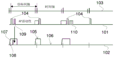
FIG. 1 illustrates a conventional Wi-Fi communication method;
FIG. 2 illustrates an apparatus capable of efficiently receiving data;
FIG. 3 illustrates a process for efficiently receiving data; and
FIG. 4 is a schematic diagram of an integrated circuit manufacturing system.
Detailed Description
The following description is presented by way of example to enable any person skilled in the art to make and use the invention. The present invention is not limited to the embodiments described herein and various modifications to the disclosed embodiments will be apparent to those skilled in the art.
The following describes a network that transmits data between wireless communication devices. The data is described herein as being sent in data packets and/or frames and/or messages. This term is used for convenience and ease of description. Packets, frames, and messages have different formats in different communication protocols. Some communication protocols use different terminology. Thus, it will be understood that the terms "packet" and "frame" as well as "message" are used herein to refer to any signal, data or message transmitted over a network.
Wi-Fi communication protocols are commonly used for many wireless applications between computing devices, web servers, and the like. The apparatus, methods, and networks disclosed below will be described with reference to apparatus and networks that may operate in accordance with the IEEE 802.11Wi-Fi communication protocol. However, the general principles described below may be applied to devices and systems operating in accordance with other communication protocols (such as bluetooth, 3GPP, LTE, etc.).
Figure 1 shows a prior art Wi-Fi network in which the device operates in a power saving mode. The figure shows activity between an Access Point (AP)101 and a Station (STA) 102. The top row 103 in fig. 1 represents the time axis.
The transceiver of the STA 102 may be in one of two different power states: (i) awakening: the STA transceiver is fully powered (as shown at 105) or (ii) dozes: the STA transceiver is unable to receive data and consumes very low power or no power (as shown at 106).
The AP 101 periodically broadcasts a beacon 104, which beacon 104 may include an indication to the STAs 102 of whether the AP 101 has any data to transmit to the STAs 102. The time between each beacon broadcast is referred to as the beacon interval. The STA 102 may know the beacon interval and thus enter an awake state so that the STA 102 may listen for beacons from the AP 101. The transceiver power rises from the doze state to the awake state, as indicated at 107, and receives a beacon frame 104.
In a Power Save (PS) mode (which may be a default operating mode for the STA), if the beacon 104 indicates that there are data frames buffered for that STA 102, a message, such as a PS-poll frame 108, is generated and transmitted that causes the buffered data frames 109 to be transmitted from the AP 101. The indication may be provided in a Traffic Indication Map (TIM) in the beacon. The AP 101 transmits a single buffered data frame 109 to the STA 102 only in response to the PS poll from the STA 102. In PS mode, the STA 102 will be in a doze state and enter an awake state to receive beacon frames, receive broadcast and multicast transmissions following a particular receive beacon frame, to transmit and wait for a response to the transmitted PS poll frame to receive buffered data frames. When the beacon indicates that there is no data for the STA 102, the STA does not send a PS-poll message and enters the doze state. In the figure, data 110 at AP 101 is data for another STA (not shown). The beacon received by the STA 120 may indicate that the data 110 is for another STA, so the transceiver at the STA 102 does not send a PS-poll message and switches to the doze state.
The Data frame 109 may include a "More Data (More Data)" field that may be set to indicate to the STA 102 whether there are additional Data frames buffered at the AP 101 to be transmitted to the STA 102. If the more data field in the received data indicates that more traffic is buffered for that STA 102, the STA 102 should poll the AP using PS-poll messages when convenient until no more data frames are buffered for that STA 102. If the more data field indicates that there is no more data buffered for the STA 102, the STA 102 will enter the doze state.
The STA 102 may operate in an active mode instead of a PS mode. In the active mode, the STA 102 may receive frames at any time and the STA 102 is continuously in an awake state. An STA 102 operating in active mode will have its receiver continuously powered up. The STA 102 may indicate to the AP 101 in which mode (PS or active) the STA 102 is operating. This indication may be made via a power management field in a frame sent by the STA 102 to the AP 101. For example, the STA 102 may send a Null-Data/QoS-Null-Data frame with the power management bit set to 0 to indicate that the STA 102 is in the active mode. When the STA 102 is operating in active mode, the AP 101 will not buffer any data frames for that STA 102 for power management reasons. Data frames destined for the STA 102 in active mode will be sent directly to the STA 102 without waiting for the PS poll to be received first by the AP 101. Thus, because the STA 102 does not need to transmit a PS-poll message to cause the AP to transmit data, the STA 102 does not need to interpret the beacon frame to determine whether there is any data waiting for the STA 102.
In the power save mode, the STA 102 is required to send a PS-poll message to the AP 101 every data frame to be received. This helps the STA 102 save power because the STA 102 will only be awake when there is data to receive. However, when there is a large amount of traffic to be sent from the AP 101 to the STA 102, sending a PS-poll frame at each frame to be received may result in high latency and lower throughput. Thus, it may be more efficient to switch the STA 102 from the power save mode to the active mode in high traffic situations. In the case when there is low traffic and the STA 102 is operating in active mode, if there are only a small number of data packets to send, the STA 102 continuously listening may not be power efficient.
Fig. 2 illustrates an apparatus 200, which apparatus 200 may operate as a STA and may be able to provide STAs with greater power efficiency, lower latency, and higher throughput than legacy STAs using a hybrid approach that combines the benefits of both power save and active modes.
To send a message, the processor 203 may drive the RF front-end 202, which RF front-end 202 in turn causes the antenna 201 to transmit the appropriate RF signal. Signals received at the antenna 201 (e.g., from an AP) may be pre-processed (e.g., by analog filtering and amplification) by the RF front end 202, which the RF front end 202 presents corresponding signals to the processor 203 for decoding. The apparatus includes a controller 211, as will be described in more detail below, the controller 211 can monitor the received signals and control the mode of operation.
The device further comprises a clock 208, which clock 208 can be switched on or off by the microprocessor 204 in order to save power, and optionally an external connection 209, which external connection 209 is adapted to exchange information with other components (not shown) connected to the device 200 or integrated with the device 200. The external connection 209 may be wired or wireless. The device also includes a power source 210, which may be a battery. The device may also be powered by a power source.
The RF front end 202 and the baseband processor 203 may be implemented on one or more integrated circuits.
Where the wireless communication device operates according to two or more communication protocols, the wireless communication device may have separate transceiver circuitry for each communication protocol, in which case the device of fig. 2 would additionally have additional antennas, RF front ends and baseband processors for each communication protocol it supports. Alternatively, one or more of the antenna, the RF front end, and the baseband processor may be shared by two or more of the communication protocols through which the device is configured to communicate.
Fig. 3 illustrates a process that may be performed by an apparatus 200 (e.g., the apparatus 200 may be a STA) to implement an efficient hybrid power save and active mode method. At step 301, the STA 200 is in PS mode. This mode may be a default mode for STA 200.
At step 302, the activity level of STA 200 is monitored. The activity level of a STA may be determined based on one or a combination of two or more of the following metrics: (i) a number of data packets received during a time period; (ii) an amount of data received over a period of time; (iii) a number of "more data" indications in a more data field of a packet received over a period of time; and (iv) the type or priority of the incoming data (which may be based on, for example, the IEEE 802.11 user preference value in each received data packet). Other suitable metrics may be used, such as traffic characteristics from applications that use STAs to transmit/receive data. The activity level is monitored to help infer the level of incoming traffic that will be coming in from the AP. If the current activity level is high, it may be inferred that there may be more urgent incoming traffic for the STA. If the current activity level is low, it can be inferred that there may not be a lot of incoming traffic.
The period of time for monitoring the activity level may depend on which mode STA 200 is currently operating in. Preferably, the monitoring period when the STA 200 operates in the power saving mode is smaller than the monitoring period when operating in the active mode. One advantage of this is that it allows the STA 200 to quickly detect potentially high levels of traffic and quickly switch from a power save mode to an active mode to ensure that high levels of incoming traffic are quickly received. Having a longer monitoring period in the active mode helps to ensure that traffic is no longer high before switching to the power saving mode. For example, the monitoring period when in active mode may be between 400ms and 600ms (preferably about 500 ms). When in the power saving mode, the monitoring period may be between 200ms and 400ms (preferably 300 ms).
At step 303, it is determined whether the monitored activity level is above or below a threshold activity level. If the monitored activity level is above the threshold, it is inferred that there will be a high level of incoming traffic for STA 200 (step 305). If the monitored activity level is below the threshold, then it is inferred at step 304 that there will be low level incoming traffic for STA 200. Then, the mode is maintained or switched to the power saving mode, thereby returning to step 301. The STA 200 may also notify the AP that it enters PS mode if the mode switches from active mode to PS mode.
The threshold may be fixed or variable and depends on the implementation. For example, if the number of received packets is used for monitoring activity, the threshold may be, for example, at least 600 packets per second (preferably at least about 800 data per second). If the input data rate is used to monitor the activity level, the threshold may be, for example, at least 5Mbit per second (preferably at least 10Mbit per second or so). If the activity level is monitored by counting the number of times the more data field is set to indicate further data to be sent, the threshold may be, for example, at least 5 data packets indicating more data per second are received (preferably at least about 10 data packets indicating more data per second). If the activity level is measured according to the IEEE 802.11 user priority values, the threshold may be set, for example, such that high priority traffic (like voice or audio) causes the STA 200 to wake up and for low priority traffic (like best effort or background) causes the STA 200 to be in power save.
In one example, the apparatus may switch between the active mode and the PS mode depending on whether the monitored activity level is greater than or less than the same threshold. In another example, the apparatus may switch from PS mode to active mode if the activity level is greater than a first threshold, and switch from active mode to PS mode if the activity level falls below a second, different threshold (which is preferably lower than the first threshold). Providing a lower second threshold may help maintain low latency and avoid frequent switching between modes as compared to having a single threshold when the activity level is about the single threshold level.
The threshold value is variable. For example, the threshold may vary depending on the amount of power available to the apparatus 200 or depending on the power mode of the apparatus 200 (which may be user-selectable). If the available power is low or the device 200 is in a power saving mode, the threshold may be increased so that a higher level of activity is required to switch or maintain the device in an active mode. Generally, this will help to save more power, but at the cost of higher latency for incoming traffic. In another example, if the available power is high and/or the data to be received is critical, the threshold may be lowered such that a lower level of activity is required to switch or maintain the device in an active mode. Generally, this will help to reduce latency, but at the cost of higher power usage.
At step 305, it is inferred from the monitored traffic level being above the threshold that the level of incoming traffic to be received from the AP may be high. Thus, at step 306, STA 200 switches to (or remains in) the active mode. If STA 200 switches from PS mode to active mode, STA 200 will inform the AP that it enters active mode. The AP then sends any data packets for that STA 200 to the STA 200 without first waiting for a PS poll from the STA 200. Thus, the STA 200 will not be required to send a PS-poll message, which releases the communication medium. Furthermore, in active mode, STA 200 need not interpret the TIM field in any beacon received from the AP. This helps to save processor resources. Processing then returns to step 302 to continue monitoring the activity level.
The process of fig. 3 allows a STA to save power when it is predicted that it will have low incoming traffic and reduce latency when it is predicted that it will have high or important incoming traffic. Further, the process provides for more efficient use of the communication medium because polling messages are not required to be transmitted by the STA to the AP when there is high incoming traffic. STAs that switch to active mode during high traffic will also be less burdened to the AP because the AP sends data packets directly rather than having to buffer the data packets because it is waiting for PS-poll messages.
The decision to switch or maintain the mode of operation may also depend on other factors. For example, if the battery powering STA 200 is low, the STA may switch to (or remain in) a power save mode even if it is inferred that there is high level of incoming traffic.
The activity level may also be monitored to help infer other scenarios that may affect the operation of STA 200. For example, in an example scenario, STA 200 may be part of a portable device (such as a smartphone) that traverses multiple AP coverage areas (e.g., Wi-Fi hotspots). STA 200 may monitor changes in the identifier (e.g., SSID) of the AP over a period of time to determine whether STA 200 is stationary or in progress. If it is determined that STA 200 is on the go, the device may switch to (or remain in) the active mode so that the device receives data as soon as possible before moving to the next hotspot.
The above-described processing may be implemented using communication protocols other than Wi-Fi. For example, the processing may be implemented on a mobile network device (such as an LTE device).
The apparatus of fig. 2 is shown to include a number of functional blocks. This is merely illustrative and is not intended to define a strict division between different logical elements of such an entity. Each functional block may be provided in any suitable manner.
In general, any of the functions, methods, techniques, or components described above may be implemented in software, firmware, hardware (e.g., fixed logic circuitry), or any combination thereof. The terms "module," "function," "component," "element," "unit," "block," and "logic" may be used herein to generally represent software, firmware, hardware, or any combination thereof. In the case of a software implementation, the module, function, component, element, unit, block, or logic represents program code that performs specified tasks when executed on a processor. The algorithms and methods described herein may be executed by one or more processors executing code that causes the processors to perform the algorithms/methods. Examples of a computer-readable storage medium include Random Access Memory (RAM), Read Only Memory (ROM), optical disks, flash memory, hard disk memory, and other storage devices that may use magnetic, optical, and other techniques to store instructions or other data and that may be accessed by a machine.
The terms computer program code and computer readable instructions as used herein refer to any kind of executable code for a processor, including code expressed in a machine language, an interpreted language, or a scripting language. Executable code includes binary code, machine code, byte code, code defining an integrated circuit (such as a hardware description language or netlist), and code expressed in programmable language code (such as C, Java or OpenCL). The executable code may be, for example, any kind of software, firmware, script, module or library that, when executed, processed, interpreted, compiled, executed, as appropriate, at a virtual machine or other software environment, causes a processor of a computer system supporting the executable code to perform the tasks specified by the code.
A processor, computer, or computer system may be any kind of device, machine, or special purpose circuit, or collection or portion thereof, having processing capabilities that enable the execution of instructions. The processor may be any kind of general or special purpose processor, such as a CPU, GPU, system on chip, state machine, media processor, Application Specific Integrated Circuit (ASIC), programmable logic array, Field Programmable Gate Array (FPGA), or the like. A computer or computer system may include one or more processors.
It is also contemplated to include software, such as HDL (hardware description language) software, defining the hardware configuration as described herein, used to design an integrated circuit or to configure a programmable chip to achieve the desired functionality. That is, a computer readable storage medium may be provided having computer readable program code encoded thereon in the form of an integrated circuit defining data set which, when processed in an integrated circuit manufacturing system, configures the system to manufacture an apparatus configured to perform any of the methods described herein, or to manufacture an apparatus including any of the devices described herein.
The integrated circuit definition dataset may be in the form of computer code, such as a netlist (code for configuring a programmable chip), a hardware description language (including Register Transfer Level (RTL) code) that defines any level of integrated circuit, a high-level circuit representation (such as Verilog or VHDL), and a low-level circuit representation (such as OASIS and GDSII). A logically defined higher-level representation of an integrated circuit, such as RTL, may be processed at a computer system configured for generating, in the context of a software environment, fabrication definitions for the integrated circuit that include definitions of circuit elements and rules for combining those elements to generate a fabrication definition that represents the integrated circuit so defined. Generally, as with software executing at a computer system to define a machine, one or more intermediate user steps (e.g., providing commands, variables, etc.) may be required in order for a computer system configured to generate a manufacturing definition for an integrated circuit to execute code defining the integrated circuit to generate the manufacturing definition for the integrated circuit.
An example of processing an integrated circuit definition data set at an integrated circuit manufacturing system to configure the system as a manufacturing device will now be described with respect to fig. 4.
Fig. 4 illustrates an example of an Integrated Circuit (IC) manufacturing system 1002, the IC manufacturing system 1002 including a layout processing system 1004 and an integrated circuit generation system 1006. The IC manufacturing system 1002 is configured to receive an IC definition dataset (e.g., defining an apparatus as described in any example herein), process the IC definition dataset, and generate an IC from the IC definition dataset (e.g., embodying an apparatus as described in any example herein). The processing of the IC definition data set configures the IC manufacturing system 1002 to manufacture integrated circuits embodying an apparatus as described in any of the examples herein.
The layout processing system 1004 is configured to receive and process the IC definition data set to determine a circuit layout. Methods of determining circuit layouts from IC definition data sets are known in the art and may involve, for example, synthesizing RTL code to determine gate level representations of circuits to be generated, for example, from logic components (e.g., nand, nor, and, or, multiplexing, and flip-flop components). The circuit layout may be determined from a gate level representation of the circuit by determining location information for the logic component. This may be done automatically or by user intervention to optimize the circuit layout. When the layout processing system 1004 has determined the circuit layout, the layout processing system 1004 may output a circuit layout definition to the IC generation system 1006.
As is known in the art, the IC generation system 1006 generates ICs from circuit layout definitions. For example, the IC generation system 1006 may implement a semiconductor device fabrication process that generates ICs, which may involve a multi-step sequence of lithographic and chemical processing steps during which electronic circuits are progressively created on wafers made of semiconducting materials. The circuit layout definition may be in the form of a mask that may be used in a lithographic process to generate an IC from the circuit definition. Alternatively, the circuit layout definition provided to the IC generation system 1006 may be in the form of computer readable code that the IC generation system 1006 may use to form an appropriate mask for generating an IC.
The different processes performed by the IC manufacturing system 1002 may all be implemented in one location, for example, by a party. Alternatively, the IC manufacturing system 1002 may be a distributed system, such that some of the processes may be performed at different locations and by different parties. For example, some of the following stages may be performed in different locations and/or by different parties: (i) synthesizing RTL code representing the IC definition dataset to form a gate level representation of the circuit to be generated, (ii) generating a circuit layout based on the gate level representation, (iii) forming a mask from the circuit layout, and (iv) manufacturing the integrated circuit using the mask.
In other examples, processing the integrated circuit definition data set at the integrated circuit manufacturing system may configure the system as a manufacturing device without processing the IC definition data set to determine the circuit layout. For example, an integrated circuit definition dataset may define a configuration of a reconfigurable processor (such as an FPGA), and processing of the dataset may configure an IC manufacturing system to generate the reconfigurable processor with the defined configuration (e.g., by loading configuration data to the FPGA).
In some embodiments, the integrated circuit fabrication definition data set may, when processed in an integrated circuit fabrication system, cause the integrated circuit fabrication system to generate an apparatus as described herein. For example, configuring an integrated circuit manufacturing system from an integrated circuit manufacturing definition dataset in the manner described above with respect to fig. 4 may result in the manufacture of an apparatus as described herein.
In some examples, the integrated circuit definition dataset may include software that runs on or is combined with hardware defined at the dataset. In the example shown in fig. 4, the IC generation system may also be configured by the integrated circuit definition dataset to load firmware onto the integrated circuit at the time of manufacture of the integrated circuit in accordance with program code defined at the integrated circuit definition dataset, or to otherwise provide the integrated circuit with program code for use with the integrated circuit.
The applicant hereby discloses in isolation each individual feature described herein and any combination of two or more such features, to the extent that such features or combinations are capable of being carried out based on the present specification as a whole in the light of the common general knowledge of a person skilled in the art, irrespective of whether such features or combinations of features solve any problems disclosed herein. In view of the foregoing description it will be evident to a person skilled in the art that various modifications may be made within the scope of the invention.
Claims (18)
1. An apparatus capable of communicating according to a wireless communication protocol, the apparatus comprising:
a transceiver configured to receive data packets from a remote device, each data packet comprising an indication of whether the remote device has a further data packet to transmit, the transceiver being operable in a first mode or a second mode, wherein:
in the first mode, the transceiver is configured to: (i) in response to receiving the indication that the remote device has additional data packets to send, sending a polling message to the remote device; and (ii) listen for the further data packet; and
in the second mode, the transceiver is configured to: (i) in response to receiving the indication that the remote device has additional data packets to send, not sending a polling message to the remote device; and (ii) listen for data packets regardless of whether the received data packet indicates that the remote device has additional data packets to send; and
a controller configured to
Monitoring an activity level for the transceiver by measuring a number of data packets received over a period of time indicating that the remote device has additional data packets to transmit;
comparing the activity level to a threshold; and is
Causing the transceiver to operate in the first mode or the second mode depending on the comparison.
2. The apparatus of claim 1, wherein the controller is configured to monitor the activity level by measuring a rate of a number of data packets received over a period of time.
3. The apparatus of claim 1, wherein the controller is configured to monitor the activity level by measuring a rate of an amount of data received over a period of time.
4. The apparatus of claim 1, wherein the controller is configured to monitor the activity level by determining a priority for the received data.
5. The apparatus of claim 4, wherein the controller is configured to cause the transceiver to operate in the second mode if the priority is associated with video and/or voice data.
6. The apparatus of any one of claims 1 to 5, wherein the transceiver is configured to listen for data packets for a greater amount of time in the second mode than in the first mode.
7. The apparatus according to any one of claims 1 to 5, wherein the transceiver is configured to listen for data packets intermittently in the first mode and to listen for data packets continuously in the second mode.
8. The apparatus of any of claims 1-5, wherein, in response to operating in the second mode, the transceiver is configured to indicate to the remote apparatus that the apparatus is operating in the second mode.
9. The apparatus of any of claims 1-5, wherein the wireless communication protocol is a Wi-Fi protocol.
10. The apparatus of claim 9, wherein the first mode is a Power Save (PS) mode and the second mode is an active mode according to the Wi-Fi protocol.
11. The apparatus of claim 9, wherein the indication of whether the remote apparatus has additional data packets to send depends on a more data field of a Wi-Fi data packet, and wherein the polling message is a PS poll.
12. The apparatus of claim 11, wherein the controller is configured to monitor the activity level by measuring a rate of receiving data packets having the more data field set to indicate that the remote apparatus has additional data packets to transmit.
13. The apparatus of any of claims 1 to 5, wherein the monitoring of the activity level comprises: monitoring for changes in identifiers received from one or more remote devices.
14. The apparatus of any of claims 1-5, wherein the transceiver is caused to operate in the first mode or the second mode further dependent on a power level of a battery powering the transceiver.
15. The apparatus of any of claims 1 to 5, wherein the controller is configured to cause the transceiver to operate in the second mode in response to the monitored activity level being greater than a first threshold, and to cause the transceiver to operate in the first mode in response to the monitored activity level being less than a second threshold; and
wherein the second threshold is different from the first threshold.
16. A method of communicating according to a wireless communication protocol, the method comprising:
receiving data packets from a remote device, each data packet including an indication of whether the remote device has a further data packet to send;
operating the transceiver in a first mode or a second mode, wherein:
in the first mode, the transceiver: (i) in response to receiving the indication that the remote device has additional data packets to send, sending a polling message to the remote device; and (ii) listen for the further data packet; and is
In the second mode, the transceiver: (i) in response to receiving the indication that the remote device has additional data packets to send, not sending a polling message to the remote device; and (ii) listen for data packets regardless of whether the received data packet indicates that the remote device has additional data packets to send;
monitoring an activity level for the transceiver by measuring a number of data packets received over a period of time indicating that the remote device has additional data packets to transmit;
comparing the activity level to a threshold; and is
Causing the transceiver to operate in the first mode or the second mode depending on the comparison.
17. The method of claim 16, wherein monitoring the activity level further comprises: monitoring for a change in an identifier of one or more remote devices.
18. The method of claim 16 or 17, further comprising: causing the transceiver to operate in the second mode in response to the monitored activity level being greater than a first threshold, and causing the transceiver to operate in the first mode in response to the monitored activity level being less than a second threshold; and is
Wherein the second threshold is different from the first threshold.
Applications Claiming Priority (2)
| Application Number | Priority Date | Filing Date | Title |
|---|---|---|---|
| GB1521461.2 | 2015-12-04 | ||
| GB1521461.2A GB2545024B (en) | 2015-12-04 | 2015-12-04 | Intelligent power saving |
Publications (2)
| Publication Number | Publication Date |
|---|---|
| CN106851794A CN106851794A (en) | 2017-06-13 |
| CN106851794B true CN106851794B (en) | 2021-05-07 |
Family
ID=55234448
Family Applications (1)
| Application Number | Title | Priority Date | Filing Date |
|---|---|---|---|
| CN201611093044.9A Active CN106851794B (en) | 2015-12-04 | 2016-12-01 | Apparatus and method capable of communicating according to a wireless communication protocol |
Country Status (4)
| Country | Link |
|---|---|
| US (2) | US11627529B2 (en) |
| EP (2) | EP3177079B1 (en) |
| CN (1) | CN106851794B (en) |
| GB (1) | GB2545024B (en) |
Families Citing this family (8)
| Publication number | Priority date | Publication date | Assignee | Title |
|---|---|---|---|---|
| GB2545024B (en) * | 2015-12-04 | 2019-01-02 | Imagination Tech Ltd | Intelligent power saving |
| WO2018206105A1 (en) * | 2017-05-10 | 2018-11-15 | Telefonaktiebolaget Lm Ericsson (Publ) | A communication node and method for handling communications between nodes of a system |
| CN109561487B (en) * | 2017-09-25 | 2022-03-04 | 中兴通讯股份有限公司 | Method and device for reducing energy consumption of mobile terminal and mobile terminal |
| US11178566B2 (en) | 2017-11-17 | 2021-11-16 | Texas Instruments Incorporated | Power saving medium access in congested network environments |
| CN113038581A (en) * | 2017-12-25 | 2021-06-25 | 维沃移动通信有限公司 | Control channel monitoring method, monitoring indication method, terminal and network equipment |
| US11570715B2 (en) * | 2020-09-07 | 2023-01-31 | Mediatek Inc. | Power saving with latency control mechanism of electronic device |
| US20220321403A1 (en) * | 2021-04-02 | 2022-10-06 | Nokia Solutions And Networks Oy | Programmable network segmentation for multi-tenant fpgas in cloud infrastructures |
| TWI792599B (en) * | 2021-10-05 | 2023-02-11 | 瑞昱半導體股份有限公司 | Wireless communication system, wireless access point, and electronic device |
Citations (5)
| Publication number | Priority date | Publication date | Assignee | Title |
|---|---|---|---|---|
| EP1473951A3 (en) * | 2003-05-02 | 2006-07-05 | Nokia Corporation | A method for saving power in a wireless terminal and a terminal therefore |
| CN103313201A (en) * | 2012-03-14 | 2013-09-18 | 中兴通讯股份有限公司 | Traffic indication information transmission method and device |
| CN104335645A (en) * | 2012-06-07 | 2015-02-04 | 高通股份有限公司 | System and method for intelligent power save notification |
| CN104813718A (en) * | 2012-11-30 | 2015-07-29 | 摩托罗拉移动有限责任公司 | Pass data to wireless station |
| CN105025561A (en) * | 2011-08-31 | 2015-11-04 | 高通股份有限公司 | Power save with data fetch time, with end of data indication, and with more data acknowledgement |
Family Cites Families (8)
| Publication number | Priority date | Publication date | Assignee | Title |
|---|---|---|---|---|
| US7660578B2 (en) * | 2003-05-02 | 2010-02-09 | Nokia Corporation | Method for saving power in a wireless terminal and a terminal |
| JP2006014167A (en) * | 2004-06-29 | 2006-01-12 | Nec Corp | Power saving method/program/recording medium for wireless lan, terminal station, and wireless lan system |
| US7590100B2 (en) * | 2005-12-23 | 2009-09-15 | Motorola, Inc. | Method for packet polling in a WLAN |
| US7668129B2 (en) * | 2006-03-30 | 2010-02-23 | Intel Corporation | Learning mechanism to configure power save parameters for automatic power save delivery |
| US20090046711A1 (en) * | 2007-08-14 | 2009-02-19 | Nokia Corporation | Data rate adaptation enhancement |
| WO2013019225A1 (en) * | 2011-08-03 | 2013-02-07 | Draeger Medical Systems, Inc. | Throughput-based active mode trigger |
| EP3022960B8 (en) * | 2013-07-16 | 2019-10-09 | Avast Software s.r.o. | Mobile device tracking prevention method and system |
| GB2545024B (en) * | 2015-12-04 | 2019-01-02 | Imagination Tech Ltd | Intelligent power saving |
-
2015
- 2015-12-04 GB GB1521461.2A patent/GB2545024B/en active Active
-
2016
- 2016-11-25 EP EP16200758.7A patent/EP3177079B1/en active Active
- 2016-11-25 EP EP19165577.8A patent/EP3522616B1/en active Active
- 2016-12-01 CN CN201611093044.9A patent/CN106851794B/en active Active
- 2016-12-05 US US15/368,809 patent/US11627529B2/en active Active
-
2022
- 2022-06-07 US US17/834,609 patent/US11968622B2/en active Active
Patent Citations (5)
| Publication number | Priority date | Publication date | Assignee | Title |
|---|---|---|---|---|
| EP1473951A3 (en) * | 2003-05-02 | 2006-07-05 | Nokia Corporation | A method for saving power in a wireless terminal and a terminal therefore |
| CN105025561A (en) * | 2011-08-31 | 2015-11-04 | 高通股份有限公司 | Power save with data fetch time, with end of data indication, and with more data acknowledgement |
| CN103313201A (en) * | 2012-03-14 | 2013-09-18 | 中兴通讯股份有限公司 | Traffic indication information transmission method and device |
| CN104335645A (en) * | 2012-06-07 | 2015-02-04 | 高通股份有限公司 | System and method for intelligent power save notification |
| CN104813718A (en) * | 2012-11-30 | 2015-07-29 | 摩托罗拉移动有限责任公司 | Pass data to wireless station |
Also Published As
| Publication number | Publication date |
|---|---|
| US20170164285A1 (en) | 2017-06-08 |
| GB2545024B (en) | 2019-01-02 |
| US20220303896A1 (en) | 2022-09-22 |
| GB2545024A (en) | 2017-06-07 |
| EP3177079A1 (en) | 2017-06-07 |
| GB201521461D0 (en) | 2016-01-20 |
| CN106851794A (en) | 2017-06-13 |
| EP3177079B1 (en) | 2019-05-01 |
| US11968622B2 (en) | 2024-04-23 |
| EP3522616A1 (en) | 2019-08-07 |
| EP3522616B1 (en) | 2021-08-11 |
| US11627529B2 (en) | 2023-04-11 |
Similar Documents
| Publication | Publication Date | Title |
|---|---|---|
| US11968622B2 (en) | Intelligent power saving | |
| CN113038578B (en) | Site awakening method and site | |
| US10638423B2 (en) | Group wake-up and keep-alive indication | |
| US20190253973A1 (en) | Wake-up method and device | |
| CN109951892B (en) | Power efficient communication of group addressed frames | |
| CN105813179A (en) | Method, device and equipment of batch wake-up equipment | |
| WO2021062612A1 (en) | Communication method and apparatus | |
| WO2023241292A1 (en) | Communication method and apparatus | |
| CN106879051A (en) | Power reduction method and electronic installation | |
| WO2025167419A1 (en) | Communication method and related device | |
| JP2024531491A (en) | Method, device and system for saving energy in terminal | |
| WO2016161547A1 (en) | Method and apparatus for transmitting indication message to be received | |
| CN118201041B (en) | A communication method and related equipment | |
| JP2025527919A (en) | Communication method and communication device | |
| CN119300125A (en) | A Wake-up Signal Monitoring Method and Communication Device | |
| CN119866650A (en) | Low power wake-up signal monitoring | |
| EP4727219A1 (en) | Communication method, apparatus and system | |
| WO2025113181A1 (en) | Communication method, apparatus and system | |
| CN120021310A (en) | A communication method and a communication device | |
| CN121510228A (en) | Communication methods, communication devices and communication systems | |
| CN120224374A (en) | Communication method and communication device | |
| WO2025162073A1 (en) | Communication method, and apparatus | |
| CN120380838A (en) | Communication method and related device | |
| CN121753421A (en) | Communication method, access point device, station device and communication system | |
| WO2026067621A1 (en) | Code point determination method and apparatus, and terminal and network-side device |
Legal Events
| Date | Code | Title | Description |
|---|---|---|---|
| PB01 | Publication | ||
| PB01 | Publication | ||
| SE01 | Entry into force of request for substantive examination | ||
| SE01 | Entry into force of request for substantive examination | ||
| TA01 | Transfer of patent application right |
Effective date of registration: 20210331 Address after: Trondheim Applicant after: NORDIC SEMICONDUCTOR ASA Address before: Hertfordshire Applicant before: Imagination Technologies Ltd. |
|
| TA01 | Transfer of patent application right | ||
| GR01 | Patent grant | ||
| GR01 | Patent grant |