CN106843258B - Omni-directional tilting trolley seesaw device and balance control method thereof - Google Patents
Omni-directional tilting trolley seesaw device and balance control method thereof Download PDFInfo
- Publication number
- CN106843258B CN106843258B CN201710240057.2A CN201710240057A CN106843258B CN 106843258 B CN106843258 B CN 106843258B CN 201710240057 A CN201710240057 A CN 201710240057A CN 106843258 B CN106843258 B CN 106843258B
- Authority
- CN
- China
- Prior art keywords
- trolley
- circular rail
- seesaw
- rail groove
- platform
- Prior art date
- Legal status (The legal status is an assumption and is not a legal conclusion. Google has not performed a legal analysis and makes no representation as to the accuracy of the status listed.)
- Active
Links
Images


Classifications
-
- G—PHYSICS
- G05—CONTROLLING; REGULATING
- G05D—SYSTEMS FOR CONTROLLING OR REGULATING NON-ELECTRIC VARIABLES
- G05D1/00—Control of position, course, altitude or attitude of land, water, air or space vehicles, e.g. using automatic pilots
- G05D1/08—Control of attitude, i.e. control of roll, pitch, or yaw
- G05D1/0891—Control of attitude, i.e. control of roll, pitch, or yaw specially adapted for land vehicles
-
- Y—GENERAL TAGGING OF NEW TECHNOLOGICAL DEVELOPMENTS; GENERAL TAGGING OF CROSS-SECTIONAL TECHNOLOGIES SPANNING OVER SEVERAL SECTIONS OF THE IPC; TECHNICAL SUBJECTS COVERED BY FORMER USPC CROSS-REFERENCE ART COLLECTIONS [XRACs] AND DIGESTS
- Y02—TECHNOLOGIES OR APPLICATIONS FOR MITIGATION OR ADAPTATION AGAINST CLIMATE CHANGE
- Y02T—CLIMATE CHANGE MITIGATION TECHNOLOGIES RELATED TO TRANSPORTATION
- Y02T10/00—Road transport of goods or passengers
- Y02T10/60—Other road transportation technologies with climate change mitigation effect
- Y02T10/72—Electric energy management in electromobility
Landscapes
- Engineering & Computer Science (AREA)
- Aviation & Aerospace Engineering (AREA)
- Radar, Positioning & Navigation (AREA)
- Remote Sensing (AREA)
- Physics & Mathematics (AREA)
- General Physics & Mathematics (AREA)
- Automation & Control Theory (AREA)
- Toys (AREA)
- Control Of Position, Course, Altitude, Or Attitude Of Moving Bodies (AREA)
Abstract
本发明公开了一种可全方位倾斜的小车跷跷板装置及其平衡控制方法,其全向轮支撑组件包括圆周均布的三个全向轮,三个全向轮的轴线向下交汇于一点,设有检测对应全向轮转动参数的绝对式编码器和增量式编码器;其跷跷板平台包括上、下圆形轨槽,下圆形轨槽通过其底部同轴设置的半球体置于三个全向轮上,下圆形轨槽上设有陀螺仪传感器,一圆形轨槽内设有自由运动小车,另一圆形轨槽内设有可控小车,各圆形轨槽的底部和侧部圆周均布设有检测对应小车位置的霍尔传感器,各小车上设有检测其自身运动速度的编码器。本发明能够绕任意方向倾斜,大大地提高了跷跷板平台平衡控制系统的维度,从而扩大了跷跷板平台控制理论研究的范围与深度。
The invention discloses a seesaw device for a trolley that can be tilted in all directions and a balance control method thereof. The omnidirectional wheel support assembly includes three omnidirectional wheels uniformly distributed on the circumference, and the axes of the three omnidirectional wheels converge at one point downwards. It is equipped with an absolute encoder and an incremental encoder to detect the rotation parameters of the corresponding omnidirectional wheel; its seesaw platform includes upper and lower circular rail grooves, and the lower circular rail groove is placed in three There are gyro sensors on the upper and lower circular rail grooves of an omnidirectional wheel, a free-moving trolley is installed in one circular rail groove, and a controllable trolley is installed in the other circular rail groove. The bottom of each circular rail groove Hall sensors for detecting the position of the corresponding trolley are evenly distributed on the circumference of the side and side, and each trolley is provided with an encoder for detecting its own movement speed. The invention can tilt around any direction, greatly improves the dimension of the balance control system of the seesaw platform, thereby expanding the scope and depth of the control theory research of the seesaw platform.
Description
技术领域technical field
本发明涉及平衡控制技术,具体为一种可全方位倾斜的小车跷跷板装置及其平衡控制方法。The invention relates to balance control technology, in particular to a seesaw device for a trolley that can tilt in all directions and a balance control method thereof.
背景技术Background technique
小车跷跷板平衡控制实验装置具有结构简单、运动机理易于分析等良好的物理特性,是进行运动控制理论研究的一种实验平台,目前常运用于大学生电子设计大赛、智能车大赛等表演展示领域。The trolley seesaw balance control experimental device has good physical characteristics such as simple structure and easy analysis of motion mechanism. It is an experimental platform for theoretical research on motion control. Currently, it is often used in performances such as college student electronic design competitions and smart car competitions.
现有的小车跷跷板实验平台通常是由可以绕固定方向倾斜的跷跷板以及可以在跷跷板上自由运动的小车组成,其基本的控制原理是通过单轴的倾角传感器检测跷跷板的倾斜状态,并实时调整小车相对跷跷板的位置来使跷跷板保持动态平衡。然而,现有的小车跷跷板实验装置,其中的跷跷板只能单方向倾斜,以这种小车跷跷板实验系统进行控制理论研究时,其研究的范围会受到一定的限制,比如控制系统的维数。The existing seesaw test platform for trolleys is usually composed of a seesaw that can tilt around a fixed direction and a trolley that can move freely on the seesaw. The basic control principle is to detect the tilt state of the seesaw through a single-axis inclination sensor and adjust the trolley in real time. The relative position of the seesaw is used to keep the seesaw in dynamic balance. However, in the existing seesaw experimental device, the seesaw can only be tilted in one direction. When using this seesaw experimental system for control theory, the research scope will be limited, such as the dimension of the control system.
如果能够将只能绕固定方向转动的单自由度跷跷板改为可以绕空间任意方向转动的空间多自由度跷跷板,则可以大大地提高小车跷跷板平衡控制系统的维度,从而扩大小车跷跷板控制理论研究的范围与深度。If the single-degree-of-freedom seesaw that can only rotate around a fixed direction can be changed into a space multi-degree-of-freedom seesaw that can rotate around any direction in space, the dimension of the balance control system of the trolley seesaw can be greatly improved, thereby expanding the research scope of the trolley seesaw control theory range and depth.
目前尚未见到有可以绕任意轴转动的小车跷跷板实验平台。Have not yet seen the dolly seesaw experimental platform that can rotate around any axis yet.
发明内容Contents of the invention
为此,本发明提出了一种可全方位倾斜的小车跷跷板装置及其平衡控制方法。Therefore, the present invention proposes a seesaw device for a trolley that can tilt in all directions and a balance control method thereof.
本发明可全方位倾斜的小车跷跷板装置,其技术方案包括跷跷板平衡机构,所不同的是所述跷跷板平衡机构包括跷跷板平台和全向轮支撑组件:The seesaw device for a trolley that can be tilted in all directions in the present invention has a technical solution including a seesaw balance mechanism, the difference is that the seesaw balance mechanism includes a seesaw platform and an omnidirectional wheel support assembly:
1、全向轮支撑组件包括分别通过对应轮架安装且圆周均布的三个全向轮,三个全向轮的轴线向下交汇于一点,各轮架上分别设有检测对应全向轮转动参数(转动幅度和转动速度)的绝对式编码器和增量式编码器。1. The omnidirectional wheel support assembly includes three omnidirectional wheels that are installed on the corresponding wheel frame and are evenly distributed on the circumference. Absolute and incremental encoders for rotational parameters (rotational amplitude and rotational speed).
2、所述跷跷板平台包括同轴设置的上、下圆形轨槽,所述下圆形轨槽通过其底部同轴设置的半球体置于三个全向轮上,上圆形轨槽或下圆形轨槽上设有可实时反馈跷跷板平台姿态的陀螺仪传感器。2. The seesaw platform includes upper and lower circular track grooves arranged coaxially, and the lower circular track groove is placed on three omnidirectional wheels through the hemisphere coaxially arranged at the bottom, and the upper circular track groove or The lower circular rail groove is provided with a gyroscope sensor that can provide real-time feedback of the attitude of the seesaw platform.
3、一圆形轨槽内设有可制造干扰因素使跷跷板平台倾斜的自由运动小车,另一圆形轨槽内设有使跷跷板平台恢复平衡的可控小车,各圆形轨槽的底部和/或侧部圆周均布设有检测对应小车位置的霍尔传感器,各小车上设有检测其自身运动速度的编码器。3. One circular rail groove is equipped with a free-moving trolley that can create disturbance factors to tilt the seesaw platform, and the other circular rail groove is equipped with a controllable trolley that restores the balance of the seesaw platform. The bottom of each circular rail groove and /or Hall sensors for detecting the position of the corresponding trolley are evenly distributed on the circumference of the side, and encoders for detecting its own movement speed are provided on each trolley.
进一步,所述自由运动小车设于下圆形轨槽内,所述可控小车设于上圆形轨槽内。Further, the free-moving trolley is set in the lower circular track groove, and the controllable trolley is set in the upper circular track groove.
更进一步,所述自由运动小车设为一个,所述可控小车设为两个。Further, there is one free-moving trolley, and two controllable trolleys.
按常规,上、下圆形轨槽的大小设计为一致。Conventionally, the sizes of the upper and lower circular rail grooves are designed to be consistent.
按常规,所述轮架通过的支撑架设于底座上。Conventionally, the support passed by the wheel frame is erected on the base.
本发明可全方位倾斜的小车跷跷板装置平衡控制方法为当跷跷板平台受到自由运动小车的干扰而发生倾斜时,可通过控制可控小车的运动使跷跷板平台恢复水平并保持动态平衡,其平衡控制步骤为:The balance control method of the trolley seesaw device that can tilt in all directions in the present invention is that when the seesaw platform is tilted due to the interference of the free moving trolley, the seesaw platform can be restored to the level and maintain dynamic balance by controlling the movement of the controllable trolley. The balance control steps for:
1、建立跷跷板系统的坐标系,其中,Z轴垂直于跷跷板平台,X轴和Y轴构成的平面在初始时刻与水平面平行。1. Establish the coordinate system of the seesaw system, wherein the Z axis is perpendicular to the seesaw platform, and the plane formed by the X axis and the Y axis is parallel to the horizontal plane at the initial moment.
2、由上、下圆形轨槽内的霍尔传感器分别测出自由运动小车和可控小车在坐标系中的坐标,通过各小车上的编码器确定各自的行走速度。2. The coordinates of the free-moving trolley and the controllable trolley in the coordinate system are respectively measured by the Hall sensors in the upper and lower circular rail grooves, and the respective walking speeds are determined by the encoders on each trolley.
3、通过跷跷板平台上的陀螺仪传感器以及各轮架上的编码器实时测量出跷跷板平台的运动状态。3. Measure the motion state of the seesaw platform in real time through the gyroscope sensor on the seesaw platform and the encoders on each wheel frame.
4、结合各小车位置坐标以及跷跷板平台的运动状态计算出自由运动小车重力对半球体球心产生的力矩和可控小车重力对半球体球心产生的力矩。4. Combining the position coordinates of each trolley and the motion state of the seesaw platform, calculate the moment generated by the gravity of the freely moving trolley on the center of the hemisphere and the moment produced by the gravity of the controllable trolley on the center of the hemisphere.
5、以自由运动小车和可控小车的合力矩为虚拟控制输入量,以减小跷跷板平台的倾角和倾角速度、恢复并保持跷跷板平台水平为目标,计算得出可控小车需要达到的位置。5. Taking the resultant torque of the free-moving car and the controllable car as the virtual control input, and aiming at reducing the inclination and inclination velocity of the seesaw platform and restoring and maintaining the level of the seesaw platform, calculate the position that the controllable car needs to reach.
6、根据可控小车需要达到的位置,结合可控小车的当前速度推算出可控小车需要的输入速度大小和方向。6. According to the position that the controllable car needs to reach, combined with the current speed of the controllable car, calculate the input speed and direction required by the controllable car.
7、按照步骤6的计算结果驱动可控小车运动。7. Drive the controllable car to move according to the calculation result in
8、重复步骤2进行下一次控制循环。8. Repeat
本发明的有益效果:Beneficial effects of the present invention:
1、本发明可全方位倾斜的小车跷跷板装置及其平衡控制方法解决了由于干扰因素导致跷跷板平台向任意方向倾斜的问题,为研究复杂的平衡控制问题提供一种简洁的通用平台。1. The trolley seesaw device capable of tilting in all directions and its balance control method of the present invention solve the problem that the seesaw platform tilts in any direction due to interference factors, and provide a simple and general platform for studying complex balance control problems.
2、本发明在一定的程度上提高了小车跷跷板平衡控制系统的维度,并在结构原理上扩大了小车跷跷板控制理论研究的范围与深度,从而更有效的训练使用者的控制系统设计开发能力。2. The present invention improves the dimension of the trolley seesaw balance control system to a certain extent, and expands the scope and depth of theoretical research on the trolley seesaw control theory in terms of structural principles, thereby more effectively training the user's ability to design and develop the control system.
3、本发明通过各种编码器和传感器实时测量小车以及跷跷板平台的运动参数实现实时平衡,更具有动态效果。3. The present invention realizes real-time balance by measuring the motion parameters of the trolley and the seesaw platform in real time through various encoders and sensors, and has a more dynamic effect.
附图说明:Description of drawings:
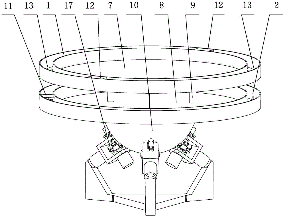
图1为本发明一种实施方式的立体结构示意图。Fig. 1 is a schematic perspective view of an embodiment of the present invention.
图2为图1实施方式中全向轮支撑组件的立体结构示意图。Fig. 2 is a three-dimensional structural schematic view of the omnidirectional wheel support assembly in the embodiment of Fig. 1 .
图3(a)为图1实施方式中下圆台及下环形轨槽的俯视图。Fig. 3(a) is a top view of the lower circular platform and the lower annular rail groove in the embodiment of Fig. 1 .
图3(b)为图3(a)中的A-A剖视图。Fig. 3(b) is a sectional view of A-A in Fig. 3(a).
图号标识:1、上圆形轨槽;2、下圆形轨槽;3、全向轮;4、轮架;5、绝对式编码器;6、增量式编码器;7、上圆台;8、下圆台;9、支撑柱体;10、半球体;11、自由运动小车;12、可控小车;13、霍尔传感器;14、支撑架;15、底座;16、陀螺仪传感器;17、全向轮支撑组件。Drawing number identification: 1. Upper circular rail groove; 2. Lower circular rail groove; 3. Omnidirectional wheel; 4. Wheel frame; 5. Absolute encoder; 6. Incremental encoder; 7. Upper round table ;8. Lower round platform; 9. Supporting cylinder; 10. Hemisphere; 11. Free movement car; 12. Controllable car; 13. Hall sensor; 14. Support frame; 15. Base; 16. Gyro sensor; 17. Omni-directional wheel support assembly.
具体实施方式Detailed ways
下面结合附图所示实施方式对本发明的技术方案作进一步说明。The technical solutions of the present invention will be further described below in conjunction with the embodiments shown in the accompanying drawings.
本发明可全方位倾斜的小车跷跷板装置的技术方案包括跷跷板平衡机构,所述跷跷板平衡机构包括跷跷板平台和全向轮支撑组件17,如图1所示。The technical solution of the seesaw device for a trolley that can tilt in all directions in the present invention includes a seesaw balance mechanism, and the seesaw balance mechanism includes a seesaw platform and an omnidirectional
所述全向轮支撑组件17包括于同一水平层面上圆周内均布的三个全向轮3,各全向轮3安装于对应的“U”型轮架4内,各轮架4分别通过各自的支撑架14安装于底座15上,三个全向轮3的轴线向下交汇于底座15中心处;所述轮架4上设有与对应全向轮3的两轮轴分别连接的绝对式编码器5和增量式编码器6,如图1、图2所示。The omnidirectional
所述跷跷板平台包括大小一致且同轴的上圆形轨槽1和下圆形轨槽2,所述上圆形轨槽1同轴设于上圆台7上,所述下圆形轨槽2同轴设于下圆台8上,上、下圆台7、8通过圆周均布的支撑柱体9连接为一体,下圆台8底部同轴设有空心的半球体10,所述半球体10内部的下圆台8底部中央设有陀螺仪传感器16,跷跷板平台通过半球体10放置于三个全向轮3上,三个全向轮3可以实现跷跷板平台在任意角度方向上的运动,满足任意自由度的倾斜;所述下圆形轨槽2内设有一个自由运动小车11,所述上圆形轨槽1内设有两个可控小车12,各小车上设有磁性元件和检测其自身运动速度的编码器,各圆形轨槽的底部和一侧面上圆周均布设有霍尔传感器13,所述霍尔传感器13上的线圈与小车上的磁性元件发生作用从而实现对小车位置的检测,如图1、图3(a)、图3(b)所示。The seesaw platform includes an upper
本发明通过全向轮支撑组件17实现了跷跷板平台在空间绕任意轴线的倾斜,当系统受到外界干扰(自由运动小车11的运行)发生倾斜时,通过陀螺仪传感器16、各种编码器、霍尔传感器13等不同类型的传感器来检测跷跷板平台以及其上自由运动小车11的相关物理参数,驱动可控小车12到达适当的位置来使跷跷板平台恢复水平并保持动态平衡。The present invention realizes the inclination of the seesaw platform around any axis in space through the omnidirectional
具体的,本发明可全方位倾斜的小车跷跷板装置平衡控制方法,其平衡控制步骤为:Specifically, the balance control method of the trolley seesaw device that can be tilted in all directions in the present invention, the balance control steps are:
1、建立跷跷板系统的坐标系,其中,Z轴垂直于跷跷板平台,X轴和Y轴构成的平面在初始时刻与水平面平行。1. Establish the coordinate system of the seesaw system, wherein the Z axis is perpendicular to the seesaw platform, and the plane formed by the X axis and the Y axis is parallel to the horizontal plane at the initial moment.
2、通过上圆形轨槽1内的霍尔传感器13测出两个可控小车12在坐标系中的坐标,通过下圆形轨槽2内的霍尔传感器13测出自由运动小车11在坐标系中的坐标,并通过各小车上的编码器确定各自的行走速度。2. Measure the coordinates of the two
3、通过下圆台8上的陀螺仪传感器16以及各轮架4上的编码器(绝对式和增量式)实时测量出跷跷板平台的运动状态。3. Measure the motion state of the seesaw platform in real time through the
4、结合各小车位置坐标以及跷跷板平台的运动状态计算出自由运动小车11重力对半球体10球心产生的力矩和两可控小车12重力对半球体10球心产生的力矩。4. Combine the position coordinates of each trolley and the motion state of the seesaw platform to calculate the moment generated by the gravity of the freely moving
5、以自由运动小车11和两可控小车12的合力矩为虚拟控制输入量,以减小跷跷板平台的倾角和倾角速度、恢复并保持跷跷板平台水平为目标,计算得出两可控小车12需要各自达到的位置。5. Taking the resultant torque of the free-moving
6、根据两可控小车12需要达到的位置,结合各可控小车12的当前速度推算出各可控小车12需要的输入速度大小和方向。6. According to the positions that the two
7、按照步骤6的计算结果分别驱动各可控小车12运动。7. Drive each
8、重复步骤2进行下一次控制循环。8.
Claims (6)
Priority Applications (1)
| Application Number | Priority Date | Filing Date | Title |
|---|---|---|---|
| CN201710240057.2A CN106843258B (en) | 2017-04-13 | 2017-04-13 | Omni-directional tilting trolley seesaw device and balance control method thereof |
Applications Claiming Priority (1)
| Application Number | Priority Date | Filing Date | Title |
|---|---|---|---|
| CN201710240057.2A CN106843258B (en) | 2017-04-13 | 2017-04-13 | Omni-directional tilting trolley seesaw device and balance control method thereof |
Publications (2)
| Publication Number | Publication Date |
|---|---|
| CN106843258A CN106843258A (en) | 2017-06-13 |
| CN106843258B true CN106843258B (en) | 2023-05-23 |
Family
ID=59146854
Family Applications (1)
| Application Number | Title | Priority Date | Filing Date |
|---|---|---|---|
| CN201710240057.2A Active CN106843258B (en) | 2017-04-13 | 2017-04-13 | Omni-directional tilting trolley seesaw device and balance control method thereof |
Country Status (1)
| Country | Link |
|---|---|
| CN (1) | CN106843258B (en) |
Families Citing this family (8)
| Publication number | Priority date | Publication date | Assignee | Title |
|---|---|---|---|---|
| CN107131874B (en) * | 2017-06-23 | 2023-03-24 | 桂林电子科技大学 | Totally-enclosed spherical omnidirectional gyro mechanism and operation method thereof |
| CN107137062B (en) * | 2017-06-29 | 2023-04-11 | 桂林电子科技大学 | Device and method for testing human balance perception capability |
| CN107628175B (en) * | 2017-09-30 | 2022-10-28 | 桂林电子科技大学 | Ball wheel steering handlebar-free self-balancing bicycle |
| CN107628174B (en) * | 2017-09-30 | 2022-10-28 | 桂林电子科技大学 | Omnidirectional ball wheel driven handlebar-free self-balancing bicycle |
| CN107639647A (en) * | 2017-10-30 | 2018-01-30 | 桂林电子科技大学 | The wrist joint of robot mechanism of omnidirectional's wheel drive |
| CN107643761B (en) * | 2017-10-30 | 2023-06-20 | 桂林电子科技大学 | Multi-stage omnidirectional space inverted pendulum mechanism and balancing method |
| CN115771721A (en) * | 2021-09-07 | 2023-03-10 | 一汽-大众汽车有限公司 | Reciprocating transmission device driven by balance car |
| CN114129962B (en) * | 2022-01-05 | 2024-04-26 | 桂林电子科技大学 | Unicycle Riding Skills Training Device |
Citations (8)
| Publication number | Priority date | Publication date | Assignee | Title |
|---|---|---|---|---|
| CN101957250A (en) * | 2010-06-09 | 2011-01-26 | 天津职业技术师范大学 | Motion balance detection system for teeterboard of electric vehicle |
| CN103050047A (en) * | 2012-12-11 | 2013-04-17 | 燕山大学 | Self-balanced parallel movement simulator of two-freedom degree closed loop |
| CN104494721A (en) * | 2014-12-02 | 2015-04-08 | 中国矿业大学 | Mecanum wheel-based rocker omnidirectional mobile platform |
| CN105899265A (en) * | 2013-12-06 | 2016-08-24 | 创新运输系统有限责任公司 | Vehicle for the movement of a driver comprising a ball rolling on a ground surface and in any desired direction |
| CN205670259U (en) * | 2016-06-04 | 2016-11-02 | 浙江侍维波机器人科技有限公司 | The dynamic self-adapting stabilizing control system of mobile robot |
| CN106515903A (en) * | 2016-12-12 | 2017-03-22 | 上海汇聚自动化科技有限公司 | Omni-directional mobile vehicle capable of adjusting goods postures accurately |
| CN206075630U (en) * | 2016-07-25 | 2017-04-05 | 桂林电子科技大学 | Space Rotating converting means |
| CN206649346U (en) * | 2017-04-13 | 2017-11-17 | 桂林电子科技大学 | Can omnibearing tilt dolly seesaws device |
Family Cites Families (3)
| Publication number | Priority date | Publication date | Assignee | Title |
|---|---|---|---|---|
| US7581603B2 (en) * | 2004-11-15 | 2009-09-01 | Hammonds Technical Services, Inc. | Omni-directional aircraft and ordinance handling vehicle |
| TWI361747B (en) * | 2008-08-01 | 2012-04-11 | Micro Star Int Co Ltd | Concentric joint mechanism capable of rotating in multiple degrees of freedom |
| US8577516B2 (en) * | 2009-09-18 | 2013-11-05 | Honda Motor Co., Ltd. | Control device of inverted pendulum type vehicle |
-
2017
- 2017-04-13 CN CN201710240057.2A patent/CN106843258B/en active Active
Patent Citations (8)
| Publication number | Priority date | Publication date | Assignee | Title |
|---|---|---|---|---|
| CN101957250A (en) * | 2010-06-09 | 2011-01-26 | 天津职业技术师范大学 | Motion balance detection system for teeterboard of electric vehicle |
| CN103050047A (en) * | 2012-12-11 | 2013-04-17 | 燕山大学 | Self-balanced parallel movement simulator of two-freedom degree closed loop |
| CN105899265A (en) * | 2013-12-06 | 2016-08-24 | 创新运输系统有限责任公司 | Vehicle for the movement of a driver comprising a ball rolling on a ground surface and in any desired direction |
| CN104494721A (en) * | 2014-12-02 | 2015-04-08 | 中国矿业大学 | Mecanum wheel-based rocker omnidirectional mobile platform |
| CN205670259U (en) * | 2016-06-04 | 2016-11-02 | 浙江侍维波机器人科技有限公司 | The dynamic self-adapting stabilizing control system of mobile robot |
| CN206075630U (en) * | 2016-07-25 | 2017-04-05 | 桂林电子科技大学 | Space Rotating converting means |
| CN106515903A (en) * | 2016-12-12 | 2017-03-22 | 上海汇聚自动化科技有限公司 | Omni-directional mobile vehicle capable of adjusting goods postures accurately |
| CN206649346U (en) * | 2017-04-13 | 2017-11-17 | 桂林电子科技大学 | Can omnibearing tilt dolly seesaws device |
Non-Patent Citations (2)
| Title |
|---|
| Masaaki Kumagai ; Takaya Ochiai.Development of a robot balancing on a ball.《2008 International Conference on Control, Automation and Systems》.2008,全文. * |
| 贾中华 ; 张少昆 ; .球上平衡移动机器人线性二次型最优控制.北京信息科技大学学报(自然科学版).2013,(第06期),全文. * |
Also Published As
| Publication number | Publication date |
|---|---|
| CN106843258A (en) | 2017-06-13 |
Similar Documents
| Publication | Publication Date | Title |
|---|---|---|
| CN106843258B (en) | Omni-directional tilting trolley seesaw device and balance control method thereof | |
| CN107063570B (en) | Omni-directional tiltable motion test bench and control method | |
| US8269447B2 (en) | Magnetic spherical balancing robot drive | |
| Kumaga et al. | Development of a robot balanced on a ball—Application of passive motion to transport— | |
| CN104461018B (en) | Electromagnetic type multi-degree of freedom virtual roaming platform | |
| EP3316735B1 (en) | Motion control seat input device | |
| CN104656684A (en) | Method for controlling tri-axis stabilization tripod head with brushless motors by using single IMU sensors | |
| EA027337B1 (en) | Two-wheeled gyro-stabilized vehicle and method for controlling such a vehicle | |
| US20200088758A1 (en) | System for stabilizing an object to control tipping during omnidirectional movement | |
| JP2004167676A5 (en) | ||
| US9610511B1 (en) | Amusement park ride vehicle including a chassis driven to have heave and sway motions | |
| CN120578171A (en) | Motion control method of mobile robot and mobile robot | |
| CN106828643A (en) | A kind of omni-directional movement ball shape robot | |
| CN205699105U (en) | A kind of step trailing type omnidirectional treadmill | |
| CN103600795A (en) | Self-balancing bicycle based on disk grating | |
| CN206067368U (en) | Omni-directional wheel, including the robot moving platform and mobile robot of omni-directional wheel | |
| CN206648781U (en) | Can omnibearing tilt exercise test platform | |
| CN106393108A (en) | Independent-state single-spheroid self-balanced movement device | |
| CN207871441U (en) | A kind of shuttlecock robot | |
| CN104494725A (en) | Robot | |
| CN206649346U (en) | Can omnibearing tilt dolly seesaws device | |
| CN107131874B (en) | Totally-enclosed spherical omnidirectional gyro mechanism and operation method thereof | |
| CN108393882A (en) | Robot pose control method and robot | |
| Kim et al. | A rolling robot: Design and implementation | |
| CN204673629U (en) | The single wheel self-balance robot of horizontal gyroscope structure |
Legal Events
| Date | Code | Title | Description |
|---|---|---|---|
| PB01 | Publication | ||
| PB01 | Publication | ||
| SE01 | Entry into force of request for substantive examination | ||
| SE01 | Entry into force of request for substantive examination | ||
| GR01 | Patent grant | ||
| GR01 | Patent grant | ||
| EE01 | Entry into force of recordation of patent licensing contract | ||
| EE01 | Entry into force of recordation of patent licensing contract |
Application publication date: 20170613 Assignee: Nanning Thumb Cloud Information Technology Co.,Ltd. Assignor: GUILIN University OF ELECTRONIC TECHNOLOGY Contract record no.: X2023980046596 Denomination of invention: A small car seesaw device that can tilt in all directions and its balance control method Granted publication date: 20230523 License type: Common License Record date: 20231108 |