CN106575135B - Peripheral holding device - Google Patents
Peripheral holding device Download PDFInfo
- Publication number
- CN106575135B CN106575135B CN201580041800.0A CN201580041800A CN106575135B CN 106575135 B CN106575135 B CN 106575135B CN 201580041800 A CN201580041800 A CN 201580041800A CN 106575135 B CN106575135 B CN 106575135B
- Authority
- CN
- China
- Prior art keywords
- peripheral
- computing device
- housing
- securing portion
- cradle
- Prior art date
- Legal status (The legal status is an assumption and is not a legal conclusion. Google has not performed a legal analysis and makes no representation as to the accuracy of the status listed.)
- Active
Links
Images


Classifications
-
- G—PHYSICS
- G06—COMPUTING OR CALCULATING; COUNTING
- G06F—ELECTRIC DIGITAL DATA PROCESSING
- G06F1/00—Details not covered by groups G06F3/00 - G06F13/00 and G06F21/00
- G06F1/16—Constructional details or arrangements
- G06F1/1613—Constructional details or arrangements for portable computers
- G06F1/1633—Constructional details or arrangements of portable computers not specific to the type of enclosures covered by groups G06F1/1615 - G06F1/1626
- G06F1/1656—Details related to functional adaptations of the enclosure, e.g. to provide protection against EMI, shock, water, or to host detachable peripherals like a mouse or removable expansions units like PCMCIA cards, or to provide access to internal components for maintenance or to removable storage supports like CDs or DVDs, or to mechanically mount accessories
-
- G—PHYSICS
- G06—COMPUTING OR CALCULATING; COUNTING
- G06F—ELECTRIC DIGITAL DATA PROCESSING
- G06F1/00—Details not covered by groups G06F3/00 - G06F13/00 and G06F21/00
- G06F1/16—Constructional details or arrangements
- G06F1/1613—Constructional details or arrangements for portable computers
- G06F1/1626—Constructional details or arrangements for portable computers with a single-body enclosure integrating a flat display, e.g. Personal Digital Assistants [PDAs]
-
- G—PHYSICS
- G06—COMPUTING OR CALCULATING; COUNTING
- G06F—ELECTRIC DIGITAL DATA PROCESSING
- G06F1/00—Details not covered by groups G06F3/00 - G06F13/00 and G06F21/00
- G06F1/16—Constructional details or arrangements
- G06F1/1613—Constructional details or arrangements for portable computers
- G06F1/1633—Constructional details or arrangements of portable computers not specific to the type of enclosures covered by groups G06F1/1615 - G06F1/1626
- G06F1/1637—Details related to the display arrangement, including those related to the mounting of the display in the housing
- G06F1/1643—Details related to the display arrangement, including those related to the mounting of the display in the housing the display being associated to a digitizer, e.g. laptops that can be used as penpads
-
- G—PHYSICS
- G06—COMPUTING OR CALCULATING; COUNTING
- G06F—ELECTRIC DIGITAL DATA PROCESSING
- G06F1/00—Details not covered by groups G06F3/00 - G06F13/00 and G06F21/00
- G06F1/16—Constructional details or arrangements
- G06F1/1613—Constructional details or arrangements for portable computers
- G06F1/1633—Constructional details or arrangements of portable computers not specific to the type of enclosures covered by groups G06F1/1615 - G06F1/1626
- G06F1/1656—Details related to functional adaptations of the enclosure, e.g. to provide protection against EMI, shock, water, or to host detachable peripherals like a mouse or removable expansions units like PCMCIA cards, or to provide access to internal components for maintenance or to removable storage supports like CDs or DVDs, or to mechanically mount accessories
- G06F1/166—Details related to functional adaptations of the enclosure, e.g. to provide protection against EMI, shock, water, or to host detachable peripherals like a mouse or removable expansions units like PCMCIA cards, or to provide access to internal components for maintenance or to removable storage supports like CDs or DVDs, or to mechanically mount accessories related to integrated arrangements for adjusting the position of the main body with respect to the supporting surface, e.g. legs for adjusting the tilt angle
-
- G—PHYSICS
- G06—COMPUTING OR CALCULATING; COUNTING
- G06F—ELECTRIC DIGITAL DATA PROCESSING
- G06F3/00—Input arrangements for transferring data to be processed into a form capable of being handled by the computer; Output arrangements for transferring data from processing unit to output unit, e.g. interface arrangements
- G06F3/01—Input arrangements or combined input and output arrangements for interaction between user and computer
- G06F3/03—Arrangements for converting the position or the displacement of a member into a coded form
- G06F3/033—Pointing devices displaced or positioned by the user, e.g. mice, trackballs, pens or joysticks; Accessories therefor
- G06F3/0354—Pointing devices displaced or positioned by the user, e.g. mice, trackballs, pens or joysticks; Accessories therefor with detection of two-dimensional [2D] relative movements between the device, or an operating part thereof, and a plane or surface, e.g. 2D mice, trackballs, pens or pucks
- G06F3/03545—Pens or stylus
-
- G—PHYSICS
- G06—COMPUTING OR CALCULATING; COUNTING
- G06F—ELECTRIC DIGITAL DATA PROCESSING
- G06F2200/00—Indexing scheme relating to G06F1/04 - G06F1/32
- G06F2200/16—Indexing scheme relating to G06F1/16 - G06F1/18
- G06F2200/163—Indexing scheme relating to constructional details of the computer
- G06F2200/1632—Pen holder integrated in the computer
-
- G—PHYSICS
- G06—COMPUTING OR CALCULATING; COUNTING
- G06F—ELECTRIC DIGITAL DATA PROCESSING
- G06F2200/00—Indexing scheme relating to G06F1/04 - G06F1/32
- G06F2200/16—Indexing scheme relating to G06F1/16 - G06F1/18
- G06F2200/163—Indexing scheme relating to constructional details of the computer
- G06F2200/1633—Protecting arrangement for the entire housing of the computer
-
- G—PHYSICS
- G06—COMPUTING OR CALCULATING; COUNTING
- G06F—ELECTRIC DIGITAL DATA PROCESSING
- G06F2200/00—Indexing scheme relating to G06F1/04 - G06F1/32
- G06F2200/16—Indexing scheme relating to G06F1/16 - G06F1/18
- G06F2200/163—Indexing scheme relating to constructional details of the computer
- G06F2200/1634—Integrated protective display lid, e.g. for touch-sensitive display in handheld computer
Landscapes
- Engineering & Computer Science (AREA)
- Computer Hardware Design (AREA)
- Theoretical Computer Science (AREA)
- General Engineering & Computer Science (AREA)
- Human Computer Interaction (AREA)
- Physics & Mathematics (AREA)
- General Physics & Mathematics (AREA)
- Telephone Set Structure (AREA)
- Microelectronics & Electronic Packaging (AREA)
- User Interface Of Digital Computer (AREA)
- Casings For Electric Apparatus (AREA)
Abstract
Description
背景background
平板计算设备可包括诸如指示笔之类的可替换的输入设备。然而,指示笔的存储可造成若干设计挑战。对这个问题有两个传统解决方案。在第一示例中,内部槽被用来通过摩擦力或通过双推(push-push)式机制存储并保持该指示笔。Tablet computing devices may include alternative input devices such as a stylus. However, storage of the stylus can pose several design challenges. There are two traditional solutions to this problem. In a first example, an internal slot is used to store and hold the stylus by friction or by a push-push mechanism.
这可能造成在设备内部需要额外空间和部分的问题。这也可导致对于移动配置而言是不理想的在设备复杂性、设备的整体大小方面的增加,并且可能因此妨碍了用户对该设备的体验。This can create problems requiring additional space and sections inside the device. This may also result in an increase in device complexity, the overall size of the device, which is not ideal for mobile configurations, and may therefore hinder the user's experience with the device.
在另一实例中,挂绳和笔帽被使用。此传统解决方案也可能造成问题。例如,挂绳可在某种程度上用作不受控附属物,并因此勾住其他物体,笔帽往往因可被使用的保持力的限制而让笔落出,等等。In another example, a lanyard and cap are used. This traditional solution can also cause problems. For example, lanyards can act to some extent as uncontrolled appendages and thus hook on other objects, pen caps tend to let the pen fall out due to limitations in the holding force that can be used, etc.
概述Overview
描述了外围保持设备技术。在一个或多个实现中,外围保持设备包括计算设备固定部分和外围固定部分。计算设备固定部分被配置成可移除地啮合计算设备,使得使用用户的一只或多只手可将该计算设备固定部分固定到计算设备外壳的第一侧并可从计算设备外壳的第一侧移除。外围固定部分被连接到计算设备固定部分并且被配置成经由与外壳的第一侧相对的外壳的第二侧可移除地啮合外围设备,使得使用用户的一只或多只手可将该外围设备固定到外围固定部分并可从外围固定部分移除。Peripheral hold device technology is described. In one or more implementations, the peripheral retention device includes a computing device securing portion and a peripheral securing portion. The computing device securing portion is configured to removably engage the computing device such that the computing device securing portion can be secured to the first side of the computing device housing and accessible from the first side of the computing device housing using one or more hands of a user. side removed. The peripheral securing portion is connected to the computing device securing portion and is configured to removably engage the peripheral device via a second side of the housing opposite the first side of the housing such that the peripheral can be accessed using one or more hands of a user The device is fixed to and removable from the peripheral fixing portion.
在一个或多个实现中,计算设备包括显示设备、外壳以及一个或多个模块。外壳具有被配置成由用户的一只或多只手握持的形状因子并包括在显示设备被固定于外壳的情况下支持显示设备的不同的观看位置的可移动的支架。支架被配置成可移除地啮合外围保持设备,使得使用用户的一只或多只手可将该外围保持设备固定到支架并可从支架移除,使用用户的一只或多只手可将外围设备固定到外围保持设备并可从外围保持设备移除。一个或多个模块至少部分地以硬件方式实现,并被配置成响应于从外围设备接收的输入而执行一个或多个操作。In one or more implementations, a computing device includes a display device, a housing, and one or more modules. The housing has a form factor configured to be held by one or more hands of a user and includes a movable stand that supports different viewing positions of the display device while the display device is secured to the housing. The bracket is configured to removably engage the peripheral retention device such that the peripheral retention device can be secured to and removed from the bracket using one or more hands of a user, and can be removed using one or more hands of a user. The peripheral device is fixed to and removable from the peripheral holding device. One or more modules are implemented at least in part in hardware and are configured to perform one or more operations in response to input received from a peripheral device.
在一个或多个实现中,系统包括指示笔和包括具有手持式配置的外壳的计算设备。外壳包括支架,该支架可移动以在显示设备被固定于外壳的情况下支持显示设备的不同的观看位置。支架被配置成可移除地啮合外围保持设备,使得使用用户的一只或多只手可将该外围保持设备固定到支架并可从支架移除,并且使用用户的一只或多只手可将指示笔固定到外围保持设备并可从外围保持设备移除。In one or more implementations, a system includes a stylus and a computing device including a housing having a handheld configuration. The housing includes a stand that is movable to support different viewing positions of the display device while the display device is secured to the housing. The bracket is configured to removably engage the peripheral retention device such that the peripheral retention device can be secured to and removed from the bracket using one or more hands of a user and can be removed using one or more hands of a user. The stylus is secured to and removable from the peripheral holder.
提供本概述以便以简化的形式介绍以下在详细描述中进一步描述的一些概念。本概述并非旨在标识出要求保护的主题的关键特征或必要特征,亦非旨在用作辅助确定要求保护的主题的范围。This summary is provided to introduce some concepts in a simplified form that are further described below in the Detailed Description. This Summary is not intended to identify key features or essential features of the claimed subject matter, nor is it intended to be used as an aid in determining the scope of the claimed subject matter.
附图简述Brief Description of Drawings
结合附图来描述具体实施方式。在附图中,附图标记最左边的数字标识该附图标记首次出现的附图。在说明书和附图的不同实例中使用相同的附图标记可指示相似或相同的项目。附图中所表示的各实体可指示一个或多个实体并且因而在讨论中可互换地作出对各实体的单数或复数形式的引用。The specific embodiments are described in conjunction with the accompanying drawings. In the figures, the left-most digit(s) of a reference number identifies the figure in which the reference number first appears. The use of the same reference numbers in different instances in the specification and the drawings may indicate similar or identical items. Various entities represented in the figures may refer to one or more entities and thus references to the various entities in the singular or plural are interchangeably made in the discussion.
图1是可用于采用本文描述的技术以固定外围设备的示例实现中的环境的图示。1 is an illustration of an environment that may be used in an example implementation that employs the techniques described herein to secure peripheral devices.
图2例示出了图1的包括处于闭合位置的支架的计算设备的侧视图。2 illustrates a side view of the computing device of FIG. 1 including the stand in a closed position.
图3例示出了图1的具有处于示例打开位置的支架的计算设备的侧视图。3 illustrates a side view of the computing device of FIG. 1 with the stand in an example open position.
图4例示出了具有处于闭合位置的支架的计算设备的后视图。4 illustrates a rear view of a computing device with the stand in a closed position.
图5例示出了具有处于打开位置的支架的计算设备的后视图。5 illustrates a rear view of a computing device with a stand in an open position.
图6和7分别例示出了计算设备的侧视图和后视图,在示例中处于打开位置的支架包括用于固定指示笔的外围保持设备。6 and 7 illustrate side and rear views, respectively, of a computing device, with the stand in an example in an open position including a peripheral holding device for securing a stylus.
图8a更详细地示出了图6和7的外围保持设备的示例。Figure 8a shows an example of the peripheral holding device of Figures 6 and 7 in more detail.
图8b和8c示出了图8a的处于压缩状态的外围保持设备。Figures 8b and 8c show the peripheral holding device of Figure 8a in a compressed state.
图9描绘了被配置成可被连接在一起的两个分开的部分的外围保持设备的示例。9 depicts an example of a peripheral holding device configured as two separate parts that can be connected together.
图10描绘了示出第一、第二、以及第三视图的示例,所述第一、第二、以及第三视图更详细地示出了图8和9的计算设备固定部分。10 depicts an example showing first, second, and third views showing the computing device fixed portion of FIGS. 8 and 9 in greater detail.
图11描绘了图1的外围保持设备安装到外壳和从外壳移除的示例。FIG. 11 depicts an example of the peripheral retention device of FIG. 1 being mounted to and removed from the housing.
图12描绘了图1的外围保持设备被固定到外壳的支架中的腔的示例。12 depicts an example of the peripheral retention device of FIG. 1 being secured to a cavity in a bracket of a housing.
图13描绘了图1的外围保持设备的另一示例。FIG. 13 depicts another example of the peripheral retention device of FIG. 1 .
图14描绘了图1的外围保持设备的又一示例。FIG. 14 depicts yet another example of the peripheral retention device of FIG. 1 .
图15描绘了图1的外围保持设备的进一步的示例。FIG. 15 depicts a further example of the peripheral retention device of FIG. 1 .
图16例示出了包括可被实现为如参考图1-15描述的任何类型的计算设备来实现本文描述的技术的各实施例的示例设备的各个组件的示例系统。16 illustrates an example system including various components of an example device that may be implemented as any type of computing device as described with reference to FIGS. 1-15 to implement embodiments of the techniques described herein.
详细描述Detailed Description
概览Overview
计算设备可以使用各种各样外围设备以支持不同类型的与设备的用户交互。这可包括被配置成除了计算设备之外被使用的输入设备,其示例是指示笔。然而,被用于存储外围设备的传统技术往往麻烦并且妨碍了用户与外围设备和计算设备两者的交互。Computing devices may use a wide variety of peripherals to support different types of user interactions with the device. This may include an input device configured to be used in addition to a computing device, an example of which is a stylus. However, conventional techniques used to store peripherals are often cumbersome and hinder user interaction with both peripherals and computing devices.
描述了外围保持设备技术。在一个或多个实现中,外围保持设备被配置成使用计算设备固定部分来被固定到计算设备,例如被固定在外壳的腔内。外围保持设备包括外围固定部分,该外围固定部分可被配置成延伸穿过外壳的环,使得计算设备固定部分和外围固定部分被置于外壳的相对侧上。以此方式,外围保持设备具有足够的固定力,使得用户可抓握外围设备(例如,指示笔)并“拿起”计算设备而无需该计算设备以其他方式被支持。Peripheral hold device technology is described. In one or more implementations, the peripheral retention device is configured to be secured to the computing device using the computing device securing portion, eg, within a cavity of the housing. The peripheral retention device includes a peripheral securing portion that can be configured to extend through a loop of the housing such that the computing device securing portion and the peripheral securing portion are disposed on opposite sides of the housing. In this way, the peripheral holding device has sufficient retention force so that a user can grasp the peripheral device (eg, a stylus) and "pick up" the computing device without the computing device being otherwise supported.
附加地,外围固定部分的环可以是柔性的,使得即使当外围保持设备被固定到计算设备时,该计算设备可仍旧“平放”在表面上。外围保持设备可被附连于计算设备的外壳的各种不同的位置处,诸如支架或别处,如以下各节进一步描述的。Additionally, the ring of the peripheral securing portion may be flexible so that even when the peripheral holding device is secured to the computing device, the computing device may still "lay flat" on the surface. The peripheral retention device may be attached at various different locations on the housing of the computing device, such as a stand or elsewhere, as further described in the following sections.
在以下讨论中,首先描述了可采用本文描述的技术的示例环境。同样描述了可在该示例环境以及其他环境中执行的示例机制。因此,对各示例机制的使用不限于该示例环境,并且该示例环境不限于对示例机制的使用。In the following discussion, an example environment in which the techniques described herein may be employed is first described. Example mechanisms that may be implemented in this example environment as well as other environments are also described. Thus, the use of the various example mechanisms is not limited to the example environment, and the example environment is not limited to the use of the example mechanisms.
示例环境Example environment
图1是可在操作上采用本文描述的技术的一示例实现中的环境100的图示。示例环境100包括具有至少部分以硬件实现的多个计算组件104的计算设备102。这些计算组件104所示出的示例包括处理系统106和被例示为存储器108的计算机可读存储介质、外围保持设备110、电池112、以及被置于外壳116内和/或被固定到外壳116的显示设备114。可在处理系统106上执行并可在存储器108中存储的软件的示例包括操作系统118和应用120。FIG. 1 is an illustration of an
计算设备102可以各种各样的方式被配置。例如,计算设备可被配置成能够通过网络进行通信的计算机,诸如台式计算机、移动站、娱乐设备、通信地耦合至显示设备的机顶盒、无线电话、游戏控制台等等。因此,计算设备102的范围可以是从具有充足存储器和处理器资源的全资源设备(例如,个人计算机、游戏控制台)到具有有限存储器和/或处理资源的低资源设备(例如,常规机顶盒、手持式游戏控制台)。
计算设备102被进一步例示为包括操作系统118。操作系统118被配置来将计算设备102的底层功能抽象给可在计算设备102上执行的应用120。例如,操作系统118可抽象计算设备102的计算组件104,以使得可在不知晓这个底层功能“如何”实现的情况下编写应用120。例如,应用120可向操作系统118提供要被呈现并由显示设备114显示的数据,而无需理解该呈现如何被执行,可接收使用显示设备114的触摸屏功能检测到的输入,等等。操作系统118也可表示各种其他功能,诸如管理计算设备102的用户可导航的文件系统和用户界面。
计算设备102可支持各种各样不同的交互。例如,计算设备102可包括可被用户操纵来与设备进行交互的一个或多个硬件设备,其可能是诸如键盘、光标控制设备(例如,鼠标)、指示笔122等的外围设备。
在所例示出的示例中,用户的第一只手124和第二只手126被示出。用户的第一只手124被显示为正握持计算设备102的外壳116。用户的第二只手126被例示为使用指示笔122提供使用显示设备114的触摸屏功能被检测到的一个或多个输入,以执行诸如加载应用的操作。由此,输入的识别可被利用来与由计算设备102输出的用户界面进行交互,诸如与游戏、应用进行交互,浏览因特网、改变计算设备102的一个或多个设置,等等。尽管示出了指示笔122,也构想了各种其他外围设备,诸如鼠标或其他光标控制设备、输出设备、外部电源,等等。In the illustrated example, the user's
诸如所例示的指示笔122的外围设备在某种情况下可能被用户遗失,因为设备没有物理地附连到计算设备102,特别是在计算设备102的手持(即,移动)配置中。然而,用于将指示笔固定到计算设备102的传统技术可在外壳116内消耗大量空间(例如,通过用于摩擦力或通过双推式机制存储并保持指示笔的内部槽),干扰与设备的用户交互(例如,挂绳),等等。因此,外围保持设备110可被配置来将指示笔122或其他外围设备以不干扰与计算设备102的用户交互的方式固定到外壳116。一个这类配置的示例在下面被描述并且在相应的附图中被示出。Peripherals such as the illustrated
图2例示出了包括处于闭合位置200的支架202的计算设备102的侧视图。在闭合状态200下,支架202形成计算设备102的后表面204的一部分,使得支架202符合计算设备102的表面轮廓。例如,当支架202处于闭合状态200时,支架202集成到外壳116的其余部分中并且不从后表面204所形成的平面中突出。一般而言,闭合位置200支持计算设备102的各种使用场景,诸如计算设备102的手持使用。FIG. 2 illustrates a side view of
尽管支架202被例示为处于从计算设备102的侧视图中可见的闭合位置200,然而这不旨在是限制性的。例如,如在一些附图中所例示的,在一些实现中,支架202位于后表面204的包括当支架202处于闭合位置时围绕支架202的边界的镂空部分(cutout portion)内。Although
显示设备114被置于前表面104上,其表示如之前描述的用于为计算设备102提供视觉输出的功能。支架202被置于后表面204上,其允许计算设备102诸如相对于附近表面的各种操作位置。一般而言,支架202是经由材料的平坦部分形成的,诸如塑料、金属、各种合金、碳化纤维等的实例和/或组合。
如本文更详细地讨论的,支架202可调整地附连到后表面204,使得支架202可相对于后表面204被移动到不同位置。在至少一些实现中,这使得支架202能够被闭合以支持计算设备102的手持使用,如图2所示。如图3所例示,支架202还可被打开,以使得计算设备102可斜靠在虚线中示出的表面上并至少部分地由支架202支撑。例如,支架202使得计算设备102能够斜靠在邻近表面,诸如桌子、桌面、用户的膝盖等。As discussed in greater detail herein, the
在至少一些实现中,支架202包括允许不同倾斜角度(例如,显示设备114的前表面相对于该表面的不同角度)的多个预设打开位置。例如,支架202经由铰链机制206附连于计算设备102,该铰链机制允许支架202相对于后表面204的移动。因此,铰链机制206可包括闭合位置,该闭合位置使得支架202能够以闭合位置200被放置。铰链机制206可进一步包括一个或多个预设打开位置,该一个或多个预设打开位置使得支架202能够被置于一个或多个打开位置以支持计算设备102的不同操作位置,其示例如以下所述并在相应的附图中示出。In at least some implementations, the
图3例示出了具有处于示例打开位置300的支架202的计算设备102的侧视图。在打开位置300中,支架202被定位成使得计算设备102可按一定角度被置于一表面上,该角度准许观看显示设备114。FIG. 3 illustrates a side view of
图4例示出了具有处于闭合位置(例如,上面在图2中介绍的位置200)的支架202的计算设备102的后视图400。在此特定实现中,后表面204具有形成后表面204的外边界的外围部分402。4 illustrates a rear view 400 of
支架202包括第一侧边缘404、第二侧边缘406、底部边缘408以及顶部边缘410。如图所示,外围部分402围绕第一侧边缘404、第二侧边缘406和底部边缘408。顶部边缘410表示支架202在其处连接至计算设备102的区域。The
图5例示出了具有处于打开位置(例如,结合图3讨论的打开位置300)的支架202的计算设备102的后视图500。后视图500例示出了支架202被形成为如上所述的从计算设备102延伸的单个板的情况。5 illustrates a
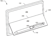
图6和7分别例示出了计算设备102的侧视图600和后视图700,在示例中处于打开位置300的支架202包括用于固定指示笔122的外围保持设备110。如前所述,在打开位置300中,支架202被定位成使得计算设备102可按一定角度被置于一表面上,该角度准许观看显示设备114。FIGS. 6 and 7 illustrate a
然而,在此示例中,外壳116的一部分(例如,在此实例中是支架202)已将外围保持设备110固定于此。此外,外围保持设备110还被例示为固定外围设备(在此实例中是指示笔122)。因此,指示笔122可通过使用外围保持设备110来被固定到计算设备102。However, in this example, a portion of housing 116 (eg,
外围保持设备110可以各种方式被配置。在所例示的示例中,外围保持设备110包括外围固定部分602,该外围固定部分602被配置为固定诸如指示笔122之类的外围设备。外围固定部分602还可以各种方式被配置。在所例示的示例中,外围固定部分602采取被固定的外围设备的互补的形状。这可通过使用诸如织物、橡胶或弹性材料之类的柔性材料来执行。其他示例也被构想,包括其中该外围固定部分602不是可弯曲的、被铸模成适应要被保持的外围设备的外表面的示例等等。The
外围固定部分602还可被配置成提供用于固定外围设备的偏置力。例如,当被形成为弹性环时,弹性体可将外围设备朝向外壳114(例如,支架)偏置,并且由此靠着外壳114保持外围设备。还构想了其他示例,诸如通过使用弹簧等。因此,外围保持设备110可采取各种不同的配置,其示例如以下所述并在相应的附图中示出。The
图8a更详细地示出了图6和7的外围保持设备110的示例800。外围保持设备110包括如前所述的外围固定部分602以及计算设备固定部分802。外围固定部分602可由诸如织物、橡胶、弹性或其他材料之类的柔性材料配置,使得当其被抵靠表面放置时外围固定部分602可如虚线箭头所示“展平”,例如当计算设备102被放置在表面804上时,使得外围固定部分602被压缩在表面804与图1的计算设备102之间。以此方式,外围保持设备110不干扰用户与计算设备102的交互。如图8b和8c所示,例如,外围固定部分可采取压缩状态,使得其具有仅为两层织物的厚度。也构想了其他示例。Figure 8a shows an example 800 of the
如图8a所示计算设备固定部分802被配置成可移除地啮合计算设备102,使得计算设备固定部分可固定到图1-7的计算设备102的外壳116并且可从图1-7的计算设备102的外壳116移除。这可以用各种方式来执行,它们的进一步讨论可结合图11-12被找到。The computing
如图9的示例900所示,外围保持设备110可被配置成两个分开的部分(例如,计算设备固定部分802和外围设备部分806),该两个分开的部分可诸如通过粘合剂、声波焊接、热激活膜等被联结在一起。也构想了诸如通过形成为单个集成单元之类的其他示例。As shown in example 900 of FIG. 9,
再次返回串接的图8和9,外围设备部分602被形成为环,诸如通过粘合剂、声波焊接等通过将设备的材料固定到其自身以形成织物环的固定部分806。外围设备部分602以交错形式被固定,使得具有从固定部分806延伸的一长度808的材料的分层结构被形成。Returning again to Figures 8 and 9 in series, the
此长度808的材料然后被附连到计算设备固定部分802的凸起部分810(例如,“脚”)从而形成分层结构,其中固定部分806被嵌套在计算设备固定部分802的凹槽内。以此方式,外围保持设备802的总体厚度可被减小,从而限制该设备对用户的正常使用的干扰。此外,凸起部分810在垂直于计算设备固定部分802的方向上支撑外围设备部分602的环,这提供了强的机械保持力。此外,这可被配置成使得用户仅可见外围设备部分602的环的织物,如结合图12示出并描述的。This
图10描绘了示出图8和9的计算设备固定部分802的第一、第二、以及第三视图1002、1004、1006的示例。第一视图1002是立体图,第二视图1004是从侧面获得的,而第三视图1006是从计算设备固定部分802的顶部获得的。计算设备固定部分802包括与外围设备部分702的交错配置互补的表面,例如,被形成为包括固定部分806和从固定部分806延伸的一长度的材料的环。FIG. 10 depicts examples showing first, second, and
例如,计算设备固定部分802可包括凸起部分810,如前所述,该凸起部分810被配置成固定到外围设备部分702的长度808。计算设备固定部分802还包括相对于凸起部分810的凹陷表面1008,该凹陷表面1008形成计算设备固定部分802与外围设备部分702之间的腔,如先前结合图8和9所描述的。For example, the computing
计算设备固定部分802还包括在计算设备固定部分802的相对侧上的凹口1010、1012,该凹口被配置成啮合于计算设备的外壳116的互补形状。这可被用于帮助支持先前所描述的高保持力,其进一步关于将外围保持设备110安装到计算设备102的外壳116和将外围保持设备110从计算设备102的外壳116移除的讨论可在下文中被找到。The computing
图11描绘了外围保持设备110安装到外壳114和从外壳114移除的示例1100。在此示例中,以截面图例示出了外壳114的支架202。支架202包括腔1102,该腔包括具有与外围保持设备的计算设备固定部分802的形状形成互补形状的边缘。FIG. 11 depicts an example 1100 of
为了安装外围保持设备110,外围设备部分602的环可从支架202的第一侧1106被拉动1104穿过腔1102到达支架202的第二侧1108。这使得外围设备部分602被压缩1110(例如,如虚线箭头所例示,环的相对侧朝向彼此移动)以适合穿过腔1102。此运动可继续以定位1112外围保持设备110的计算设备固定部分802的边缘,以啮合支架202中的腔1102的边缘,其进一步的讨论可以在下文中被找到并且在相应的附图中被示出。To install the
图12描绘了示例1200,其中外围保持设备110被固定到外壳114的支架202的腔1102。在安装时,外围固定部分602被置于支架202的第二侧上,而计算设备固定部分802被固定到外壳的第一侧1106的腔1102的边缘。FIG. 12 depicts an example 1200 in which the
例如,作为计算设备固定部分802提供的力的结果,计算设备固定部分802可弯曲并“点击”以偏置该部分和腔的边缘的接触。如图11和12所描述的此过程也可被反转以将外围保持设备110从计算设备102移除而不是将外围保持设备110固定到计算设备102。以此方式,外围保持设备110可在不使用工具的情况下通过用户的一只或多只手被固定到计算设备102并从计算设备102移除。For example, as a result of the force provided by the computing
如先前结合图10所描述并如该图的展开视图1202所示,计算设备固定部分802可包括凹口1010,该凹口1010被配置成啮合外壳114(例如在此示例中的支架202)的互补形状1204。此机制被配置成支持在外围保持设备110与支架202之间的高保持力。As previously described in connection with FIG. 10 and shown in expanded
例如,用户可用一只或多只手抓握外围固定部分602和/或由该部分固定的外围设备,并将其从支架上拉开。这可导致模拟了被用于拉动1104外围固定部分穿过腔1102的力的力。然而,凹口1010的边缘与腔1102的互补形状1204的边缘的机械啮合可被配置成抵抗这种移动,在所例示的实例中该机械啮合被配置成提供大致垂直于该拉动1104的固定力。也构想了可与先前的示例一起使用或与先前的示例分开使用的其他示例,诸如用于支持磁附连、粘合剂的使用等。For example, a user may grasp peripheral securing
因此,如在此示例中安装的计算设备固定部分802经由支架202的第二侧1108不可见。此外,如先前所描述的,外围设备部分602可被配置为柔性的,并且因此在不使用时(例如,当被放置在表面上时)最小化外围保持设备110对用户与计算设备102的交互的侵入。还构想了外围保持设备配置的各种其他示例,其讨论可以在下文中被找到并且在相应的附图中被示出。Thus, the computing
图13描绘了图1的外围保持设备110的另一示例1300。在此示例中,计算设备固定部分802被形成为将外围固定部分602固定到支架202的第二侧1108的板。外围固定部分602可被配置为柔性的,并且如前所述向外围设备提供偏置力。FIG. 13 depicts another example 1300 of the
图14描绘了图1的外围保持设备110的又一示例1400。在此示例中,计算设备固定部分802也被形成为将外围固定部分602固定到支架202的第二侧1108的板。然而,在该示例1440中,外围固定部分602通过使用计算设备固定部分802被固定于支架202的第一和第二侧1106、1108两者。例如,环的一侧可被塞在计算设备固定部分802下方,而另一侧可螺旋在支架202下方。如前所述,外围固定部分602可被配置为柔性的,并且如前所述向外围设备提供偏置力。FIG. 14 depicts yet another example 1400 of the
图15描绘了图1的外围保持设备110的进一步的示例1500。在此示例中,计算设备固定部分802也被形成为将外围固定部分602例如通过焊接固定到支架202的第一侧1106的板。在此实例中,外围固定部分602通常不是柔性的,因为其不被配置成展平的并且以相应的外围设备(例如,指示笔)的互补形状来形成。还可以设想各种其他示例而不背离其精神和范围,诸如涉及使用具有卷起端的夹子、将外围固定部分的环“拉伸”在形成为“药片”的计算设备固定部分上、在第一1106侧使用螺钉等等。FIG. 15 depicts a further example 1500 of the
示例系统和设备Example Systems and Devices
图16在1600概括地例示了包括示例计算设备1602的示例系统,该示例计算设备表示可以实现本文描述的各个技术的一个或多个计算系统和/或设备。计算设备1602例如可被构造成通过采取所形成的外壳以及由用户的一个或多个手抓握和携带的尺寸来采用移动配置,这些计算设备的所例示的示例包括移动电话、移动游戏和音乐设备和平板计算机,但还构想其他示例。还包括外围保持设备110,其可被用于保持如上所述的外围设备122。16 generally illustrates, at 1600, an example system including an example computing device 1602, which represents one or more computing systems and/or devices that may implement the various techniques described herein. The computing device 1602, for example, may be configured to assume a mobile configuration by taking a housing formed and dimensions to be grasped and carried by one or more hands of a user, illustrated examples of which include mobile phones, mobile games, and music devices and tablets, but other examples are envisioned. Also included is a
所例示的示例计算设备1602包括处理系统1604、一个或多个计算机可读介质1606、以及相互通信地耦合的一个或多个I/O接口1608。尽管没有示出,计算设备1602可进一步包括系统总线或将各种组件相互耦合的其它数据和命令传输系统。系统总线可以包括不同总线结构中的任一个或其组合,诸如存储器总线或存储器控制器、外围总线、通用串行总线和/或利用各种总线体系结构中的任一种的处理器或局部总线。也构想了各种其它示例,诸如控制和数据线。The illustrated example computing device 1602 includes a processing system 1604, one or more computer-readable media 1606, and one or more I/O interfaces 1608 communicatively coupled to each other. Although not shown, computing device 1602 may further include a system bus or other data and command transmission system that couples the various components to each other. The system bus may include any or a combination of different bus structures, such as a memory bus or memory controller, a peripheral bus, a universal serial bus, and/or a processor or local bus utilizing any of a variety of bus architectures . Various other examples are also contemplated, such as control and data lines.
处理系统1604表示使用硬件执行一个或多个操作的功能。因此,处理系统1604被例示为包括可被配置为处理器、功能块等等的硬件元件1610。这可包括在作为专用集成电路或使用一个或多个半导体构成的其它逻辑设备的硬件中的实现。硬件元件1610不受形成它们的材料或者其中利用的处理机制的限制。例如,处理器可以由半导体和/或晶体管(例如,电子集成电路(IC))构成。在这一上下文中,处理器可执行指令可以是可电子地执行的指令。Processing system 1604 represents functionality that uses hardware to perform one or more operations. Accordingly, processing system 1604 is illustrated as including hardware elements 1610 that may be configured as processors, functional blocks, and the like. This may include implementation in hardware as an application specific integrated circuit or other logic device constructed using one or more semiconductors. Hardware elements 1610 are not limited by the materials from which they are formed or the processing mechanisms utilized therein. For example, a processor may be constructed of semiconductors and/or transistors (eg, electronic integrated circuits (ICs)). In this context, processor-executable instructions may be electronically executable instructions.
计算机可读存储介质1606被例示为包括存储器/存储1612。存储器/存储1612表示与一个或多个计算机可读介质相关联的存储器/存储容量。存储器/存储组件1612可包括易失性介质(如随机存取存储器(RAM))和/或非易失性介质(如只读存储器(ROM)、闪存、光盘、磁盘等等)。存储器/存储组件1612可包括固定介质(例如,RAM、ROM、固定硬盘驱动器等)以及可移动介质(例如闪存、可移动硬盘驱动器、光盘等等)。计算机可读介质1606可以下面进一步描述的各种方式来配置。Computer readable storage medium 1606 is illustrated as including memory/storage 1612 . Memory/storage 1612 represents memory/storage capacity associated with one or more computer-readable media. The memory/storage component 1612 may include volatile media (eg, random access memory (RAM)) and/or non-volatile media (eg, read only memory (ROM), flash memory, optical disks, magnetic disks, etc.). Memory/storage component 1612 may include fixed media (eg, RAM, ROM, fixed hard drives, etc.) as well as removable media (eg, flash memory, removable hard drives, optical discs, etc.). Computer readable medium 1606 may be configured in various ways as described further below.
输入/输出接口1608表示允许用户向计算设备1602输入命令和信息的功能,并且还允许使用各种输入/输出设备向用户和/或其它组件或设备呈现信息。输入设备的示例包括键盘、光标控制设备(例如,鼠标)、话筒、扫描仪、触摸功能(例如,电容性的或被配置来检测物理触摸的其它传感器)、照相机(例如,可采用可见或诸如红外频率的不可见波长来将移动识别为不涉及触摸的手势),等等。输出设备的示例包括显示设备(例如,监视器或投影仪)、扬声器、打印机、网卡、触觉响应设备,等等。因此,计算设备1602可以按照各种方式来配置以支持用户交互。Input/output interface 1608 represents functionality that allows a user to input commands and information to computing device 1602, and also allows information to be presented to a user and/or other components or devices using various input/output devices. Examples of input devices include keyboards, cursor control devices (eg, mice), microphones, scanners, touch capabilities (eg, capacitive or other sensors configured to detect physical touch), cameras (eg, which may employ visible or other sensors such as invisible wavelengths of infrared frequencies to recognize movement as gestures that do not involve touch), etc. Examples of output devices include display devices (eg, monitors or projectors), speakers, printers, network cards, haptic responsive devices, and the like. Accordingly, computing device 1602 may be configured in various ways to support user interaction.
计算设备1602还被例示为物理地耦合到外围设备1614,所述外围设备614可物理地从计算设备1602移除,例如使用磁性。以此方式,各种不同的输入设备可以耦合到计算设备1602,从而具有各种各样的配置来支持各种各样的功能。Computing device 1602 is also illustrated as being physically coupled to peripheral device 1614, which is physically removable from computing device 1602, eg, using magnetism. In this manner, a variety of different input devices may be coupled to computing device 1602, having a variety of configurations to support a variety of functions.
此处可以在软件、硬件元件或程序模块的一般上下文中描述各种技术。一般而言,此类模块包括执行特定任务或实现特定抽象数据类型的例程、程序、对象、元件、组件、数据结构等等。本文使用的术语“模块”、“功能”和“组件”一般表示软件、固件、硬件或其组合。本文描述的技术的各特征是平台无关的,从而意味着该技术可在具有各种处理器的各种商用计算平台上实现。Various techniques may be described herein in the general context of software, hardware elements, or program modules. Generally, such modules include routines, programs, objects, elements, components, data structures, etc. that perform particular tasks or implement particular abstract data types. The terms "module," "function," and "component" as used herein generally mean software, firmware, hardware, or a combination thereof. Features of the techniques described herein are platform independent, meaning that the techniques can be implemented on a variety of commodity computing platforms with a variety of processors.
所描述的模块和技术的实现可以被存储在某种形式的计算机可读介质上或跨某种形式的计算机可读介质传输。计算机可读介质可包括可由计算设备1602访问的各种介质。作为示例而非限制,计算机可读介质可包括“计算机可读存储介质”和“计算机可读信号介质”。An implementation of the described modules and techniques may be stored on or transmitted across some form of computer-readable media. Computer-readable media may include various media that can be accessed by computing device 1602 . By way of example and not limitation, computer-readable media may include "computer-readable storage media" and "computer-readable signal media."
“计算机可读存储介质”可以指相对于仅信号传输、载波、或信号本身而言,启用对信息的持久和/或非瞬态存储的介质和/或设备。因此,计算机可读存储介质是指非信号承载介质。计算机可读存储介质包括以适合于存储如计算机可读指令、数据结构、程序模块、逻辑元件/电路、或其它数据等的方法或技术来实现的诸如易失性和非易失性、可移动和不可移动介质和/或存储设备的硬件。该计算机可读存储介质的示例包括但不限于,RAM、ROM、EEPROM、闪存或其它存储器技术、CD-ROM、数字多功能盘(DVD)或其它光存储、硬盘、磁带盒、磁带、磁盘存储或其它磁存储设备、或者可适用于存储所需信息并可由计算机访问的其它存储设备、有形介质或制品。A "computer-readable storage medium" may refer to a medium and/or device that enables persistent and/or non-transitory storage of information, as opposed to merely signaling, carrier waves, or the signals themselves. Thus, computer-readable storage media refers to non-signal bearing media. Computer-readable storage media includes volatile and non-volatile, removable storage media such as volatile and non-volatile, removable storage media implemented in methods or technologies suitable for storage of computer-readable instructions, data structures, program modules, logic elements/circuits, or other data, etc. and non-removable media and/or storage device hardware. Examples of such computer-readable storage media include, but are not limited to, RAM, ROM, EEPROM, flash memory or other memory technology, CD-ROM, digital versatile disk (DVD) or other optical storage, hard disks, magnetic cassettes, magnetic tape, magnetic disk storage or other magnetic storage devices, or other storage devices, tangible media, or articles of manufacture that may be suitable for storing the desired information and that can be accessed by a computer.
“计算机可读信号介质”可以指被配置为诸如经由网络向计算设备1602的硬件传输指令的信号承载介质。信号介质通常用诸如载波、数据信号、或其它传输机制等已调制数据信号来体现计算机可读指令、数据结构、程序模块或其他数据。信号介质还包括任何信息传送介质。术语“已调制数据信号”是指使得以在信号中编码信息的方式来设定或改变其一个或多个特征的信号。作为示例而非限制,通信介质包括有线介质,诸如有线网络或直接线路连接,以及无线介质,诸如声学、RF、红外线和其它无线介质。A "computer-readable signal medium" may refer to a signal-bearing medium configured to transmit instructions to the hardware of computing device 1602, such as via a network. Signal media typically embody computer readable instructions, data structures, program modules, or other data in a modulated data signal such as a carrier wave, data signal, or other transport mechanism. Signal media also includes any information delivery media. The term "modulated data signal" refers to a signal that causes one or more of its characteristics to be set or changed in a manner that encodes information in the signal. By way of example and not limitation, communication media includes wired media, such as a wired network or direct-line connection, and wireless media, such as acoustic, RF, infrared, and other wireless media.
如前面所描述的,硬件元件1610和计算机可读介质1606表示以硬件形式实现的模块、可编程设备逻辑和/或固定设备逻辑,其可被某些实施例采用来实现此处描述的技术的至少某些方面,诸如执行一个或多个指令。硬件可包括集成电路或片上系统、专用集成电路(ASIC)、现场可编程门阵列(FPGA)、复杂可编程逻辑器件(CPLD),和以硅或其它硬件实现的组件。在此上下文中,硬件可操作为通过指令和/或由硬件实现的逻辑来执行程序任务的处理设备,以及被用来存储用于执行的指令的硬件(例如上面描述的计算机可读存储介质)。As previously described, hardware elements 1610 and computer-readable media 1606 represent modules, programmable device logic and/or fixed device logic implemented in hardware that may be employed by certain embodiments to implement the techniques described herein. at least some aspects, such as executing one or more instructions. Hardware may include integrated circuits or systems on a chip, application specific integrated circuits (ASICs), field programmable gate arrays (FPGAs), complex programmable logic devices (CPLDs), and components implemented in silicon or other hardware. In this context, hardware is operable as a processing device that performs program tasks through instructions and/or logic implemented by hardware, as well as hardware (eg, the computer-readable storage medium described above) used to store instructions for execution. .
前面的组合也可被采用来实现在此描述的各种技术。因此,软件、硬件,或可执行模块可被实现为在某种形式的计算机可读存储介质上和/或由一个或多个硬件元件1610实现的一个或多个指令和/或逻辑。计算设备1602可被配置成实现对应于软件和/或硬件模块的特定指令和/或功能。因此,可作为软件由计算设备1602执行的模块的实现可至少部分以硬件完成,例如,通过使用计算机可读存储介质和/或处理系统1604的硬件元件1610。指令和/或功能可以是一个或多个制品(例如,一个或多个计算设备1602和/或处理系统1604)可执行/可操作的,以实现本文描述的技术、模块、以及示例。Combinations of the foregoing may also be employed to implement the various techniques described herein. Accordingly, software, hardware, or executable modules may be implemented as one or more instructions and/or logic implemented on some form of computer-readable storage medium and/or by one or more hardware elements 1610 . Computing device 1602 may be configured to implement specific instructions and/or functions corresponding to software and/or hardware modules. Thus, implementation of modules executable by computing device 1602 as software may be accomplished at least in part in hardware, eg, through the use of computer-readable storage media and/or hardware elements 1610 of processing system 1604 . The instructions and/or functions may be executable/operable by one or more articles of manufacture (eg, one or more computing devices 1602 and/or processing system 1604 ) to implement the techniques, modules, and examples described herein.
结语Epilogue
尽管用结构特征和/或方法动作专用的语言描述了各个示例实现,但可以理解,所附权利要求书中定义的各实现不必限于上述具体特征或动作。相反,这些具体特征和动作是作为实现所要求保护的特征的示例形式而公开的。Although various example implementations have been described in language specific to structural features and/or methodological acts, it is to be understood that the various implementations defined in the appended claims are not necessarily limited to the specific features or acts described above. Rather, the specific features and acts are disclosed as example forms of implementing the claimed features.
Claims (20)
Applications Claiming Priority (3)
| Application Number | Priority Date | Filing Date | Title |
|---|---|---|---|
| US14/450,023 | 2014-08-01 | ||
| US14/450,023 US9513671B2 (en) | 2014-08-01 | 2014-08-01 | Peripheral retention device |
| PCT/US2015/042551 WO2016018958A1 (en) | 2014-08-01 | 2015-07-29 | Peripheral retention device |
Publications (2)
| Publication Number | Publication Date |
|---|---|
| CN106575135A CN106575135A (en) | 2017-04-19 |
| CN106575135B true CN106575135B (en) | 2020-01-07 |
Family
ID=53887200
Family Applications (1)
| Application Number | Title | Priority Date | Filing Date |
|---|---|---|---|
| CN201580041800.0A Active CN106575135B (en) | 2014-08-01 | 2015-07-29 | Peripheral holding device |
Country Status (4)
| Country | Link |
|---|---|
| US (1) | US9513671B2 (en) |
| EP (1) | EP3175316B1 (en) |
| CN (1) | CN106575135B (en) |
| WO (1) | WO2016018958A1 (en) |
Families Citing this family (8)
| Publication number | Priority date | Publication date | Assignee | Title |
|---|---|---|---|---|
| KR101776262B1 (en) * | 2014-06-27 | 2017-09-11 | 삼성전자주식회사 | Foldable device |
| US10191986B2 (en) | 2014-08-11 | 2019-01-29 | Microsoft Technology Licensing, Llc | Web resource compatibility with web applications |
| US9705637B2 (en) | 2014-08-19 | 2017-07-11 | Microsoft Technology Licensing, Llc | Guard band utilization for wireless data communication |
| US9397723B2 (en) | 2014-08-26 | 2016-07-19 | Microsoft Technology Licensing, Llc | Spread spectrum wireless over non-contiguous channels |
| US9424048B2 (en) | 2014-09-15 | 2016-08-23 | Microsoft Technology Licensing, Llc | Inductive peripheral retention device |
| TWI594109B (en) * | 2016-10-14 | 2017-08-01 | 緯創資通股份有限公司 | Portable electronic device capable of preventing screen dumping |
| US10236710B1 (en) * | 2016-12-20 | 2019-03-19 | Quirklogic, Inc. | Stylus securing apparatus |
| US12282358B1 (en) * | 2024-11-11 | 2025-04-22 | Pioneer Square Brands, Inc. | Enhanced portable electronic device case stand system |
Citations (2)
| Publication number | Priority date | Publication date | Assignee | Title |
|---|---|---|---|---|
| CN202189301U (en) * | 2011-06-29 | 2012-04-11 | 健博贸易有限公司 | An adapter device for a tablet computer |
| CN203299717U (en) * | 2013-08-21 | 2013-11-20 | 联想(北京)有限公司 | Electronic device |
Family Cites Families (179)
| Publication number | Priority date | Publication date | Assignee | Title |
|---|---|---|---|---|
| GB2102632B (en) | 1981-07-09 | 1985-10-16 | Tdk Electronics Co Ltd | Electronic components e.g. inductors |
| GB2178570A (en) | 1985-06-07 | 1987-02-11 | Remanco Systems Inc | Computer overlay keyboard |
| US6266685B1 (en) | 1991-07-11 | 2001-07-24 | Intermec Ip Corp. | Hand-held data collection system with stylus input |
| GB9218876D0 (en) | 1992-09-07 | 1992-10-21 | Millicom Holdings Uk Ltd | Communication system |
| US5576981A (en) | 1993-11-17 | 1996-11-19 | Intermec Corporation | Portable computer with interchangeable keypad and method for operating same |
| US7123600B2 (en) | 1995-06-30 | 2006-10-17 | Interdigital Technology Corporation | Initial power control for spread-spectrum communications |
| CH687757A5 (en) | 1995-08-29 | 1997-02-14 | Stucki Ag Entwicklungen | Collection device for Writing Instruments or tools. |
| US5719898A (en) | 1995-09-29 | 1998-02-17 | Golden Bridge Technology, Inc. | Fuzzy-logic spread-spectrum adaptive power control |
| US5862133A (en) | 1996-08-02 | 1999-01-19 | Golden Bridge Technology | Packet-switched spread-spectrum system |
| US5973677A (en) | 1997-01-07 | 1999-10-26 | Telxon Corporation | Rechargeable, untethered electronic stylus for computer with interactive display screen |
| FI973837A7 (en) | 1997-09-29 | 1999-03-30 | Nokia Telecommunications Oy | Allocation of data transfer resources |
| US6807405B1 (en) | 1999-04-28 | 2004-10-19 | Isco International, Inc. | Method and a device for maintaining the performance quality of a code-division multiple access system in the presence of narrow band interference |
| US6337924B1 (en) | 1999-02-26 | 2002-01-08 | Hewlett-Packard Company | System and method for accurately recognizing text font in a document processing system |
| FR2791185B1 (en) | 1999-03-16 | 2001-06-01 | Infra Sa | LOW VOLTAGE CONNECTOR PROVIDED WITH AN ADAPTER AND ADAPTER FOR SUCH A CONNECTOR |
| US6737591B1 (en) | 1999-05-25 | 2004-05-18 | Silverbrook Research Pty Ltd | Orientation sensing device |
| BR0012916A (en) | 1999-08-06 | 2002-10-22 | Omniboard Inc | Keyboard for use as an input device for a host computer, system for use as an input mechanism for a host computer, and, process for connecting a keyboard to a host computer |
| US6468090B2 (en) | 1999-09-15 | 2002-10-22 | Fci Americas Technology, Inc. | Low inductance power connector and method of reducing inductance in an electrical connector |
| US6630943B1 (en) | 1999-09-21 | 2003-10-07 | Xsides Corporation | Method and system for controlling a complementary user interface on a display surface |
| US7203946B2 (en) | 1999-10-11 | 2007-04-10 | Hewlett-Packard Development Company, L.P. | System and method for intercepting, instrumenting and characterizing usage of an application programming interface |
| US6691176B1 (en) | 1999-11-04 | 2004-02-10 | Microsoft Corporation | Method for managing client services across browser pages |
| EP1256211A2 (en) | 2000-02-07 | 2002-11-13 | QUALCOMM Incorporated | Position determination using bluetooth devices |
| US6324209B1 (en) | 2000-02-28 | 2001-11-27 | Golden Bridge Technology Inc. | Multi-channel spread spectrum system |
| JP2001267133A (en) | 2000-03-15 | 2001-09-28 | Murata Mfg Co Ltd | Multilayer inductor |
| US6880086B2 (en) | 2000-05-20 | 2005-04-12 | Ciena Corporation | Signatures for facilitating hot upgrades of modular software components |
| US6442764B1 (en) | 2000-07-28 | 2002-09-03 | Intelligent Designs 2000 Corp. | Multi-use cap with tab for holding accessories |
| US20020036253A1 (en) | 2000-08-02 | 2002-03-28 | Lake Gary F. | Mountable holder for writing implements |
| WO2002069533A2 (en) | 2000-10-27 | 2002-09-06 | L-3 Communications Corporation | Two-dimensional channel bonding in a hybrid cdma/fdma fixed wireless access system to provide finely variable rate channels |
| JP3617958B2 (en) | 2001-03-07 | 2005-02-09 | 株式会社東芝 | Housing for display device |
| US7055146B1 (en) | 2001-03-08 | 2006-05-30 | Microsoft Corporation | Method and system for dynamically inserting modifications for identified programs |
| US6944460B2 (en) | 2001-06-07 | 2005-09-13 | Telefonaktiebolaget L M Ericsson (Publ) | System and method for link adaptation in communication systems |
| KR100386597B1 (en) | 2001-06-26 | 2003-06-09 | 엘지전자 주식회사 | apparatus and method for conversing communication protocol |
| US6918066B2 (en) | 2001-09-26 | 2005-07-12 | International Business Machines Corporation | Method and system for evaluating applications on different user agents |
| US6724914B2 (en) | 2001-10-16 | 2004-04-20 | Digimarc Corporation | Progressive watermark decoding on a distributed computing platform |
| US6938077B2 (en) | 2001-11-07 | 2005-08-30 | Microsoft Corporation | Client version advertisement service for overriding default client version properties |
| US7370120B2 (en) | 2001-12-07 | 2008-05-06 | Propel Software Corporation | Method and system for reducing network latency in data communication |
| US7069562B2 (en) | 2001-12-12 | 2006-06-27 | Sun Microsystems, Inc. | Application programming interface for connecting a platform independent plug-in to a web browser |
| US7151795B1 (en) | 2001-12-31 | 2006-12-19 | Arraycomm Llc | Method and apparatus for increasing spectral efficiency using mitigated power near band-edge |
| US7383556B1 (en) | 2002-02-08 | 2008-06-03 | Mcafee, Inc. | Extractor system, method and computer program product for managing network access on a per-application basis |
| JP2003348007A (en) | 2002-03-20 | 2003-12-05 | Nec Corp | Wireless mobile communication method and cell-site, and wireless resource management system and mobile node device |
| US7437193B2 (en) | 2002-06-28 | 2008-10-14 | Boston Scientific Neuromodulation Corporation | Microstimulator employing improved recharging reporting and telemetry techniques |
| US20040100457A1 (en) | 2002-11-21 | 2004-05-27 | Mandle Thomas C. | Method and system for switching power and loading and closing applications in a portable computing device using a removable pointing device |
| US20040120290A1 (en) | 2002-12-24 | 2004-06-24 | Makhijani Mahesh A. | Admission control in a wireless communication network |
| WO2005040990A2 (en) | 2003-10-24 | 2005-05-06 | Spencer Donald B | Tablet and notebook pc carrier |
| US7373451B2 (en) | 2003-12-08 | 2008-05-13 | The Board Of Trustees Of The Leland Stanford Junior University | Cache-based system management architecture with virtual appliances, network repositories, and virtual appliance transceivers |
| DE102004019349A1 (en) | 2003-12-23 | 2005-07-28 | BSH Bosch und Siemens Hausgeräte GmbH | Connecting device for establishing an electrical connection between a power cable and a wiring harness |
| US7483262B2 (en) | 2004-01-15 | 2009-01-27 | Hewlett-Packard Development Company, L.P. | Computer system with multiple-connector apparatus |
| US7412259B2 (en) | 2004-02-19 | 2008-08-12 | Lime Electronics Co., Ltd. | Mobile phone with USB interface |
| US20060081714A1 (en) | 2004-08-23 | 2006-04-20 | King Martin T | Portable scanning device |
| CN2750420Y (en) | 2004-04-23 | 2006-01-04 | 鸿富锦精密工业(深圳)有限公司 | Optical recording/reproducing device |
| US7400860B2 (en) | 2004-06-15 | 2008-07-15 | Rotani, Inc. | Method and apparatus for increasing data throughput |
| US7327777B2 (en) | 2004-06-17 | 2008-02-05 | General Dynamics Corporation | Method and apparatus for distributed polyphase spread spectrum communications |
| US20060012567A1 (en) | 2004-07-13 | 2006-01-19 | Todd Sicklinger | Minature optical mouse and stylus |
| ITTV20040158A1 (en) | 2004-12-30 | 2005-03-30 | Nice Spa | REMOTE CONTROLLER. |
| US7639876B2 (en) | 2005-01-14 | 2009-12-29 | Advanced Digital Systems, Inc. | System and method for associating handwritten information with one or more objects |
| JP4507909B2 (en) | 2005-02-21 | 2010-07-21 | 株式会社日立製作所 | Base station apparatus and control method for adaptively controlling channel density |
| US7549144B2 (en) | 2005-02-22 | 2009-06-16 | Microsoft Corporation | Custom API modeling for source code static analysis simulator |
| JP4476324B2 (en) | 2005-03-02 | 2010-06-09 | 富士通株式会社 | OFDM communication system and OFDM communication method |
| US20060197755A1 (en) | 2005-03-02 | 2006-09-07 | Bawany Muhammad A | Computer stylus cable system and method |
| US7653893B2 (en) | 2005-03-04 | 2010-01-26 | Microsoft Corporation | Methods and apparatus for implementing checkin policies in source code control systems |
| US7382357B2 (en) | 2005-04-25 | 2008-06-03 | Avago Technologies Ecbu Ip Pte Ltd | User interface incorporating emulated hard keys |
| US7623121B2 (en) | 2005-05-02 | 2009-11-24 | Microsoft Corporation | Flexible pen holder for a computer |
| US7568163B2 (en) | 2005-07-20 | 2009-07-28 | Applied Minds, Inc. | Method and apparatus for utilizing prescribed aspect(s) of feedback object select operation to indicate user feedback of hypermedia content unit |
| GB0521792D0 (en) | 2005-10-26 | 2005-12-07 | Ibm | A method, apparatus and computer program for validating source code |
| US20070147226A1 (en) | 2005-10-27 | 2007-06-28 | Aamod Khandekar | Method and apparatus for achieving flexible bandwidth using variable guard bands |
| CN100492301C (en) | 2005-12-23 | 2009-05-27 | 国际商业机器公司 | Method and system for avoiding software conflicts |
| US7853646B2 (en) | 2006-01-26 | 2010-12-14 | International Business Machines Corporation | Assured validation for facade method invocations |
| US8509563B2 (en) | 2006-02-02 | 2013-08-13 | Microsoft Corporation | Generation of documents from images |
| US20070283048A1 (en) | 2006-06-01 | 2007-12-06 | Nokia Corporation | Method, Apparatus and Computer Program Product for Providing Universal Information Transcoding |
| US7953295B2 (en) | 2006-06-29 | 2011-05-31 | Google Inc. | Enhancing text in images |
| JP4743154B2 (en) | 2006-07-05 | 2011-08-10 | セイコーエプソン株式会社 | Document editing apparatus, program, and storage medium |
| US8175613B2 (en) | 2006-08-04 | 2012-05-08 | Misonimo Chi Acquisitions L.L.C. | Systems and methods for determining location of devices within a wireless network |
| US7805730B2 (en) | 2006-09-21 | 2010-09-28 | Reuters America, Llc | Common component framework |
| US20080077855A1 (en) | 2006-09-21 | 2008-03-27 | Shirel Lev | Generic website |
| GB2443459A (en) | 2006-10-31 | 2008-05-07 | Hewlett Packard Development Co | Data packet incuding computing platform indication |
| US7626358B2 (en) | 2006-12-01 | 2009-12-01 | Intel Corporation | Method and device for charging peripherals |
| US8687563B2 (en) | 2007-01-09 | 2014-04-01 | Stmicroelectronics, Inc. | Simultaneous sensing and data transmission |
| US7825913B2 (en) | 2007-01-30 | 2010-11-02 | Hewlett-Packard Development Company, L.P. | Computer stylus with integrated memory |
| WO2008115237A1 (en) | 2007-03-21 | 2008-09-25 | Tegic Communications, Inc. | Interchangeable input modules associated with varying languages |
| TW200840160A (en) | 2007-03-21 | 2008-10-01 | Asustek Comp Inc | Electrical connection mechanism between a body and a base of an electronic device |
| US8416197B2 (en) | 2007-06-15 | 2013-04-09 | Ricoh Co., Ltd | Pen tracking and low latency display updates on electronic paper displays |
| US8065624B2 (en) | 2007-06-28 | 2011-11-22 | Panasonic Corporation | Virtual keypad systems and methods |
| TW200919299A (en) | 2007-08-01 | 2009-05-01 | Silverbrook Res Pty Ltd | Handheld scanner for coded surfaces |
| US8232976B2 (en) | 2010-03-25 | 2012-07-31 | Panasonic Corporation Of North America | Physically reconfigurable input and output systems and methods |
| US8241047B2 (en) | 2007-10-30 | 2012-08-14 | Super Talent Electronics, Inc. | Flash drive with spring-loaded swivel connector |
| US8418142B2 (en) | 2008-01-22 | 2013-04-09 | Oracle International Corporation | Architecture for data validation |
| US8199768B1 (en) | 2008-01-30 | 2012-06-12 | Google Inc. | Dynamic spectrum allocation and access |
| US8045482B2 (en) | 2008-02-08 | 2011-10-25 | Yahoo! Inc. | Location tracking based on proximity-based ad hoc network |
| US20090217241A1 (en) | 2008-02-22 | 2009-08-27 | Tetsuro Motoyama | Graceful termination of a web enabled client |
| US20100021022A1 (en) | 2008-02-25 | 2010-01-28 | Arkady Pittel | Electronic Handwriting |
| US8958460B2 (en) | 2008-03-18 | 2015-02-17 | On-Ramp Wireless, Inc. | Forward error correction media access control system |
| TWI420327B (en) | 2008-03-24 | 2013-12-21 | Wistron Corp | Method and related apparatus and website accessing system capable of enhancing website capability |
| US20090250366A1 (en) | 2008-04-02 | 2009-10-08 | Amir Sabber Esfahani | Adhesive Pen Holder |
| US8941590B2 (en) | 2008-04-24 | 2015-01-27 | Oblong Industries, Inc. | Adaptive tracking system for spatial input devices |
| US20110050164A1 (en) | 2008-05-07 | 2011-03-03 | Afshin Partovi | System and methods for inductive charging, and improvements and uses thereof |
| US8432939B2 (en) | 2008-05-15 | 2013-04-30 | Qualcomm Incorporated | Using guard carriers for extra channels |
| US8842076B2 (en) | 2008-07-07 | 2014-09-23 | Rockstar Consortium Us Lp | Multi-touch touchscreen incorporating pen tracking |
| US20100055928A1 (en) | 2008-07-24 | 2010-03-04 | Mitch Randall | Connector for providing power to a mobile electronic device |
| JP4653230B2 (en) | 2008-09-22 | 2011-03-16 | 株式会社エヌ・ティ・ティ・ドコモ | API inspection device and condition monitoring device |
| CN100568255C (en) | 2008-10-07 | 2009-12-09 | 珠海金山软件股份有限公司 | A method of anti-hacking on web pages |
| WO2010048746A1 (en) | 2008-10-31 | 2010-05-06 | Ebay Inc. | System and method to test executable instructions |
| US8819630B2 (en) | 2008-12-08 | 2014-08-26 | Microsoft Corporation | Automatic test tool for webpage design with micro-browsers on mobile platforms |
| CA2647704A1 (en) | 2008-12-22 | 2010-06-22 | Belden Cdt (Canada) Inc. | Coupler connector |
| NO332210B1 (en) | 2009-03-23 | 2012-07-30 | Cisco Systems Int Sarl | Interface unit between video conferencing codec and interactive whiteboard |
| US8760415B2 (en) | 2009-03-30 | 2014-06-24 | Kent Displays Incorporated | Display with overlayed electronic skin |
| US8490084B1 (en) | 2009-06-18 | 2013-07-16 | Amazon Technologies, Inc. | Installation testing in automated application distribution |
| JPWO2011004868A1 (en) | 2009-07-08 | 2012-12-20 | 京セラ株式会社 | Radio base station and communication control method |
| US20110066973A1 (en) | 2009-09-11 | 2011-03-17 | Apple Inc. | Rendering System Log Data |
| CN101650659B (en) | 2009-09-15 | 2013-07-03 | 福建升腾资讯有限公司 | Device and method for automatically installing and saving Activex control in XPe operating system |
| US8516471B2 (en) | 2009-10-06 | 2013-08-20 | International Business Machines Corporation | Detecting impact of operating system upgrades |
| US8996988B2 (en) | 2009-10-19 | 2015-03-31 | Browsera, LLC | Automated application compatibility testing |
| JP5465015B2 (en) | 2010-01-06 | 2014-04-09 | キヤノン株式会社 | Apparatus and method for digitizing documents |
| US8200251B2 (en) | 2010-01-15 | 2012-06-12 | Apple Inc. | Determining a location of a mobile device using a location database |
| US8509166B2 (en) | 2010-01-28 | 2013-08-13 | Tti Inventions D Llc | System and method for resource allocation of a LTE network integrated with femtocells |
| US8719702B2 (en) | 2010-03-09 | 2014-05-06 | Xerox Corporation | Document organizing based on page numbers |
| CN101799855B (en) | 2010-03-12 | 2012-08-22 | 北京大学 | Simulated webpage Trojan detecting method based on ActiveX component |
| US9092129B2 (en) | 2010-03-17 | 2015-07-28 | Logitech Europe S.A. | System and method for capturing hand annotations |
| JP5859513B2 (en) | 2010-03-30 | 2016-02-10 | ビーエイイー・システムズ・インフォメーション・アンド・エレクトロニック・システムズ・インテグレイション・インコーポレーテッド | Method and system for operation of spectrum manager in cognitive radio system |
| US9823831B2 (en) | 2010-04-07 | 2017-11-21 | Apple Inc. | Device, method, and graphical user interface for managing concurrently open software applications |
| US8370629B1 (en) | 2010-05-07 | 2013-02-05 | Qualcomm Incorporated | Trusted hybrid location system |
| CN201774769U (en) | 2010-06-21 | 2011-03-23 | 深圳富泰宏精密工业有限公司 | Stylus pen fixing structure |
| US9747270B2 (en) | 2011-01-07 | 2017-08-29 | Microsoft Technology Licensing, Llc | Natural input for spreadsheet actions |
| US8655944B2 (en) | 2010-10-05 | 2014-02-18 | Microsoft Corporation | Website compatibility shims |
| US8606293B2 (en) | 2010-10-05 | 2013-12-10 | Qualcomm Incorporated | Mobile device location estimation using environmental information |
| US8711552B2 (en) | 2010-10-06 | 2014-04-29 | Compal Electronics Inc. | Modular system having expandable form factor |
| TWI485555B (en) | 2010-10-29 | 2015-05-21 | Compal Electronics Inc | Electronic apparatus |
| US8832836B2 (en) | 2010-12-30 | 2014-09-09 | Verisign, Inc. | Systems and methods for malware detection and scanning |
| US8751216B2 (en) | 2010-12-30 | 2014-06-10 | International Business Machines Corporation | Table merging with row data reduction |
| US20120170966A1 (en) | 2011-01-03 | 2012-07-05 | Novak Jr James Russell | Writing implement with storage enclosure |
| US9179565B2 (en) * | 2011-01-11 | 2015-11-03 | Sung-mok Cho | Portable electronic device holder |
| US8634849B2 (en) | 2011-01-19 | 2014-01-21 | Qualcomm Incorporated | Methods and apparatus for mobile device based location determination in a communications system |
| US20120192155A1 (en) | 2011-01-20 | 2012-07-26 | Microsoft Corporation | Code advisor for web compatibility and interoperability |
| US9042653B2 (en) | 2011-01-24 | 2015-05-26 | Microsoft Technology Licensing, Llc | Associating captured image data with a spreadsheet |
| US20120249300A1 (en) | 2011-03-30 | 2012-10-04 | Avital Shlomo | Determination of location using rssi and transmit power |
| US8934500B2 (en) | 2011-04-13 | 2015-01-13 | Motorola Mobility Llc | Method and apparatus using two radio access technologies for scheduling resources in wireless communication systems |
| US8606261B2 (en) | 2011-04-19 | 2013-12-10 | Blackberry Limited | Method and system for frequency scan using a differential power metric |
| EP2710827B1 (en) | 2011-05-16 | 2019-02-27 | Telefonaktiebolaget LM Ericsson (publ) | Method and arrangement related to interference between systems |
| US9204381B2 (en) | 2011-06-08 | 2015-12-01 | St-Ericsson Sa | Probability calculation of RAT candidate |
| GB2492051B (en) | 2011-06-13 | 2015-08-26 | Neul Ltd | Channel bandwidth |
| WO2012173434A2 (en) | 2011-06-15 | 2012-12-20 | 엘지전자 주식회사 | Method for allocating wireless resources in a wireless access system, and apparatus therefor |
| DE202011103087U1 (en) | 2011-07-11 | 2011-08-25 | Fujitsu Technology Solutions Intellectual Property Gmbh | Holder for a pen on a portable electronic device and an assembly |
| US9307415B2 (en) | 2011-07-20 | 2016-04-05 | Broadcom Corporation | Methods and apparatuses for provision of a downlink synchronization group during discontinuous transmission in an unlicensed band |
| KR101873054B1 (en) | 2011-08-22 | 2018-07-02 | 삼성전자주식회사 | Stylus pen mounting apparatus for information device |
| US8947379B2 (en) | 2011-10-28 | 2015-02-03 | Atmel Corporation | Inductive charging for active stylus |
| US8761193B2 (en) | 2011-11-21 | 2014-06-24 | Broadcom Corporation | Wireless communication device capable of utilizing additional bandwidth |
| US20130179798A1 (en) | 2012-01-06 | 2013-07-11 | Microsoft Corporation | Application dissemination and feedback |
| EP2807608B1 (en) | 2012-01-23 | 2024-04-10 | Microsoft Technology Licensing, LLC | Borderless table detection engine |
| US9360893B2 (en) | 2012-03-02 | 2016-06-07 | Microsoft Technology Licensing, Llc | Input device writing surface |
| US8639266B2 (en) | 2012-04-18 | 2014-01-28 | Google Inc. | Using peer devices to locate a mobile device |
| TW201345089A (en) * | 2012-04-30 | 2013-11-01 | Ibm | An electrical adapter for identifying the connection state of network |
| US9485042B2 (en) | 2012-06-01 | 2016-11-01 | Electronics And Telecommunications Research Instit | Transmitting and receiving apparatus and method for separating multiple broadcast signals in terrestrial cloud broadcast system |
| US20130342465A1 (en) | 2012-06-13 | 2013-12-26 | Microsoft Corporation | Interchangeable Surface Translation and Force Concentration |
| US9073123B2 (en) | 2012-06-13 | 2015-07-07 | Microsoft Technology Licensing, Llc | Housing vents |
| US20130346636A1 (en) | 2012-06-13 | 2013-12-26 | Microsoft Corporation | Interchangeable Surface Input Device Mapping |
| US9063693B2 (en) | 2012-06-13 | 2015-06-23 | Microsoft Technology Licensing, Llc | Peripheral device storage |
| US20130335330A1 (en) | 2012-06-13 | 2013-12-19 | Microsoft Corporation | Media processing input device |
| US9268379B2 (en) | 2012-07-27 | 2016-02-23 | Hewlett-Packard Development Company, L.P. | Stylus and holder device associated therewith |
| US20140028635A1 (en) | 2012-07-27 | 2014-01-30 | Christoph Horst Krah | Modular stylus device |
| US8917505B2 (en) | 2012-07-31 | 2014-12-23 | Hewlett-Packard Development Company, L.P. | Positionable stand for computing device |
| US20140061406A1 (en) * | 2012-09-06 | 2014-03-06 | Eddy Nelson Chevalier | System for attaching accessories to a monitor |
| CN102855232B (en) | 2012-09-14 | 2016-02-24 | 同方知网数字出版技术股份有限公司 | A kind of tabular analysis adapts job operation |
| US9125289B2 (en) * | 2012-10-05 | 2015-09-01 | Javid Vahid | Asymmetric computer tablet frame docking system |
| US9528847B2 (en) | 2012-10-15 | 2016-12-27 | Microsoft Technology Licensing, Llc | Pictures from sketches |
| TWM449362U (en) | 2012-10-31 | 2013-03-21 | 鴻海精密工業股份有限公司 | Wireless rechargeable thin film battery with radio frequency antenna |
| US9626349B2 (en) | 2012-12-18 | 2017-04-18 | International Business Machines Corporation | Dynamically manipulating tables based on a font |
| US9939842B2 (en) * | 2013-01-03 | 2018-04-10 | Carroll Boston Correll, JR. | Electronic device combination |
| US8977212B2 (en) | 2013-03-15 | 2015-03-10 | DGS Global Systems, Inc. | Systems, methods, and devices for electronic spectrum management with remote access to data in a virtual computing network |
| US9842125B2 (en) | 2013-04-24 | 2017-12-12 | Atlys, Inc. | Nested media container, panel and organizer |
| KR20140131275A (en) | 2013-05-02 | 2014-11-12 | 삼성전자주식회사 | Method and system for handling interference between a low power network and a high power network sharing a commnon frequency band |
| US10356623B2 (en) | 2013-09-24 | 2019-07-16 | Qualcomm Incorporated | Techniques for performing carrier sense adaptive transmission in unlicensed spectrum |
| TWM482205U (en) | 2013-10-29 | 2014-07-11 | Knowmax Technology Ltd | Wireless charging system with auto-detection |
| US20150277500A1 (en) | 2014-03-28 | 2015-10-01 | Microsoft Corporation | Peripheral Device Storage |
| US10191986B2 (en) | 2014-08-11 | 2019-01-29 | Microsoft Technology Licensing, Llc | Web resource compatibility with web applications |
| US20160050529A1 (en) | 2014-08-18 | 2016-02-18 | Microsoft Corporation | Location Information from a Mobile Device |
| US9705637B2 (en) | 2014-08-19 | 2017-07-11 | Microsoft Technology Licensing, Llc | Guard band utilization for wireless data communication |
| US9805483B2 (en) | 2014-08-21 | 2017-10-31 | Microsoft Technology Licensing, Llc | Enhanced recognition of charted data |
| US9524429B2 (en) | 2014-08-21 | 2016-12-20 | Microsoft Technology Licensing, Llc | Enhanced interpretation of character arrangements |
| US9397723B2 (en) | 2014-08-26 | 2016-07-19 | Microsoft Technology Licensing, Llc | Spread spectrum wireless over non-contiguous channels |
| US20160073267A1 (en) | 2014-09-04 | 2016-03-10 | Microsoft Corporation | Intelligence for Encoded Communication Data |
| US9424048B2 (en) | 2014-09-15 | 2016-08-23 | Microsoft Technology Licensing, Llc | Inductive peripheral retention device |
-
2014
- 2014-08-01 US US14/450,023 patent/US9513671B2/en not_active Expired - Fee Related
-
2015
- 2015-07-29 EP EP15753245.8A patent/EP3175316B1/en active Active
- 2015-07-29 CN CN201580041800.0A patent/CN106575135B/en active Active
- 2015-07-29 WO PCT/US2015/042551 patent/WO2016018958A1/en not_active Ceased
Patent Citations (2)
| Publication number | Priority date | Publication date | Assignee | Title |
|---|---|---|---|---|
| CN202189301U (en) * | 2011-06-29 | 2012-04-11 | 健博贸易有限公司 | An adapter device for a tablet computer |
| CN203299717U (en) * | 2013-08-21 | 2013-11-20 | 联想(北京)有限公司 | Electronic device |
Also Published As
| Publication number | Publication date |
|---|---|
| EP3175316B1 (en) | 2019-09-25 |
| EP3175316A1 (en) | 2017-06-07 |
| US20160034001A1 (en) | 2016-02-04 |
| WO2016018958A1 (en) | 2016-02-04 |
| CN106575135A (en) | 2017-04-19 |
| US9513671B2 (en) | 2016-12-06 |
Similar Documents
| Publication | Publication Date | Title |
|---|---|---|
| CN106575135B (en) | Peripheral holding device | |
| CN105190470B (en) | Hinge mechanism for rotatable component attachment | |
| CN106164806B (en) | input device attachment | |
| US20150277500A1 (en) | Peripheral Device Storage | |
| US9063693B2 (en) | Peripheral device storage | |
| CN105144016B (en) | Additional input device, equipment and method | |
| JP3182771U (en) | Protective sheath | |
| CN103412617B (en) | Flexible hinge and dismountable attached | |
| US9170613B2 (en) | Connecting assembly and electronic device having the same | |
| US8886257B2 (en) | Electronic device | |
| CN106164807B (en) | Devices with mechanical attachment and retention features | |
| US9116670B2 (en) | Surface contact for a support component | |
| CN106687939A (en) | Inductive peripheral retention device | |
| US9864407B2 (en) | Mobile computing device dock | |
| US9122447B2 (en) | Expansion dock and portable electronic system therewith | |
| TWI432128B (en) | Supporting apparatus of electronic device | |
| CN106662891A (en) | Multi-configuration input device | |
| US20140126134A1 (en) | Portable electronic device with hinge structure | |
| KR20160016061A (en) | Protecting cover | |
| WO2015078335A1 (en) | Protecting-supporting assembly for tablet electronic product |
Legal Events
| Date | Code | Title | Description |
|---|---|---|---|
| PB01 | Publication | ||
| PB01 | Publication | ||
| SE01 | Entry into force of request for substantive examination | ||
| SE01 | Entry into force of request for substantive examination | ||
| GR01 | Patent grant | ||
| GR01 | Patent grant |