CN1060725C - Reinforcement for sealing, guiding and trimming strips - Google Patents
Reinforcement for sealing, guiding and trimming strips Download PDFInfo
- Publication number
- CN1060725C CN1060725C CN95195770A CN95195770A CN1060725C CN 1060725 C CN1060725 C CN 1060725C CN 95195770 A CN95195770 A CN 95195770A CN 95195770 A CN95195770 A CN 95195770A CN 1060725 C CN1060725 C CN 1060725C
- Authority
- CN
- China
- Prior art keywords
- slit
- sidewall
- type
- support
- matrix
- Prior art date
- Legal status (The legal status is an assumption and is not a legal conclusion. Google has not performed a legal analysis and makes no representation as to the accuracy of the status listed.)
- Expired - Fee Related
Links
Images


Classifications
-
- B—PERFORMING OPERATIONS; TRANSPORTING
- B60—VEHICLES IN GENERAL
- B60J—WINDOWS, WINDSCREENS, NON-FIXED ROOFS, DOORS, OR SIMILAR DEVICES FOR VEHICLES; REMOVABLE EXTERNAL PROTECTIVE COVERINGS SPECIALLY ADAPTED FOR VEHICLES
- B60J10/00—Sealing arrangements
- B60J10/80—Sealing arrangements specially adapted for opening panels, e.g. doors
-
- B—PERFORMING OPERATIONS; TRANSPORTING
- B60—VEHICLES IN GENERAL
- B60J—WINDOWS, WINDSCREENS, NON-FIXED ROOFS, DOORS, OR SIMILAR DEVICES FOR VEHICLES; REMOVABLE EXTERNAL PROTECTIVE COVERINGS SPECIALLY ADAPTED FOR VEHICLES
- B60J10/00—Sealing arrangements
- B60J10/15—Sealing arrangements characterised by the material
- B60J10/18—Sealing arrangements characterised by the material provided with reinforcements or inserts
-
- B—PERFORMING OPERATIONS; TRANSPORTING
- B60—VEHICLES IN GENERAL
- B60J—WINDOWS, WINDSCREENS, NON-FIXED ROOFS, DOORS, OR SIMILAR DEVICES FOR VEHICLES; REMOVABLE EXTERNAL PROTECTIVE COVERINGS SPECIALLY ADAPTED FOR VEHICLES
- B60J10/00—Sealing arrangements
- B60J10/30—Sealing arrangements characterised by the fastening means
- B60J10/32—Sealing arrangements characterised by the fastening means using integral U-shaped retainers
-
- Y—GENERAL TAGGING OF NEW TECHNOLOGICAL DEVELOPMENTS; GENERAL TAGGING OF CROSS-SECTIONAL TECHNOLOGIES SPANNING OVER SEVERAL SECTIONS OF THE IPC; TECHNICAL SUBJECTS COVERED BY FORMER USPC CROSS-REFERENCE ART COLLECTIONS [XRACs] AND DIGESTS
- Y10—TECHNICAL SUBJECTS COVERED BY FORMER USPC
- Y10T—TECHNICAL SUBJECTS COVERED BY FORMER US CLASSIFICATION
- Y10T428/00—Stock material or miscellaneous articles
- Y10T428/24—Structurally defined web or sheet [e.g., overall dimension, etc.]
- Y10T428/2419—Fold at edge
- Y10T428/24198—Channel-shaped edge component [e.g., binding, etc.]
Landscapes
- Engineering & Computer Science (AREA)
- Mechanical Engineering (AREA)
- Seal Device For Vehicle (AREA)
- Lock And Its Accessories (AREA)
Abstract
Description
本发明涉及槽形的卡紧、密封或装饰条的增强支架,它由被形成为槽的弹性材料制成,该槽具有和两侧壁成为一体的基体,所述侧壁止于限定该槽的口的纵向边缘,该材料以沿其长度方向上具有并肩地排列的多条穿通的缝隙,该缝隙包括第一和第二类型缝隙,每条第一类型的缝隙连续地穿过该基体延伸,并伸入到每个侧壁,以便使该支架在绕平行于该基体的平面且垂直于该条的长度方向上的轴弯曲时有可弯性,每个第二类型的缝隙在侧壁中形成,而且从该侧壁各自的末端边缘内的一点向该基体延伸,该第一、第二类型的缝隙沿该支架的长度方向上彼此交替地排列,第二类型的缝隙包括一种其形状是伸入并局部越过该基体的缝隙。The invention relates to a reinforcing bracket for gripping, sealing or trim strips in the form of a channel made of elastic material formed as a channel having a base body integral with two side walls which end at the limit of the channel The longitudinal edge of the mouth, the material has a plurality of piercing slits arranged side by side along its length, the slits include first and second type slits, each first type slit extending continuously through the substrate , and extend into each side wall so that the bracket is bendable when bent about an axis parallel to the plane of the base and perpendicular to the length of the bar, each second type of slit in the side wall Formed in and extending from a point within the respective end edges of the side walls toward the base, the first and second types of slits are arranged alternately with each other along the length of the bracket, the second type of slits comprising a Shapes are gaps that protrude into and partially across the substrate.
从DE-A-3743970中得知这种支架。在这种装置中,所有的第二类型的缝隙的形状是这样的:它们伸入并局部越过该支架的交替。发现这类布置生产了一种大于某些应用而言会是太软的支架。在某些应中,可能需要求生产闭式的密封、导引或装饰条以将其装在如机动车辆车体开口那样特定的开口中。若这类条用已知类型的支架增强,则其相当高的可弯曲性会使该条的闭环对于便于处置和安装而言则是过软了。本发明的目的在于解决此问题。Such a bracket is known from DE-A-3743970. In this arrangement all the slits of the second type are shaped in such a way that they protrude alternately into and partly beyond the support. It was found that this type of arrangement produced a stent which would be too soft for some applications. In some applications, it may be desirable to produce closed seals, guides or trim strips to fit in specific openings such as motor vehicle body openings. If such a strip is reinforced with a bracket of known type, its rather high flexibility would render the closed loop of the strip too soft for easy handling and installation. The purpose of the present invention is to solve this problem.
因此,这种已知的支架的特征是:该第二类型的缝隙还包括另一种形式的缝隙,这两种第二类型的不同形式的缝隙沿该侧壁彼此交替地排列,其它形式的缝隙止于不到该交替之处。Therefore, this known bracket is characterized in that the second type of slit also includes another form of slit, the different forms of the two second types of slits are arranged alternately with each other along the side wall, the other forms of slits The gap ends short of this alternation.
现仅通过举例的方式,参照附图描述实施本发明的密封,导引和装饰条,及实施本发明的加有金属支架的这类密封,导引和装饰条,在各图中:Now, by way of example only, seals, guides and trims embodying the invention, and such seals, guides and trims embodying the invention with metal brackets are described with reference to the accompanying drawings, in which:
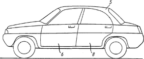
图1是其上可用该条的机动车辆车体的侧视图;Figure 1 is a side view of a motor vehicle body on which the strip may be used;
图2是按图5中的Ⅱ-Ⅱ线通过该密封和装饰条中的一种所取的剖面图;Fig. 2 is a sectional view taken along line II-II in Fig. 5 through one of the sealing and decorative strips;
图3是插在图2的该条中的金属支架之一的透视图;Figure 3 is a perspective view of one of the metal brackets inserted in the bar of Figure 2;
图4是图3中的该金属支加于其制备阶段中时的平面图;Fig. 4 is a plan view of the metal support in Fig. 3 when it is added in its preparation stage;
图5是图3中的该支座的改型的透视图;Figure 5 is a perspective view of a modification of the support in Figure 3;
图6是闭合成环状的,图2中的该密封条的视图;Fig. 6 is closed into a ring, the view of the sealing strip in Fig. 2;
图7是展示图3中的该支座在第一类型弯折后的外视的局部侧视图;Fig. 7 is a partial side view showing the external view of the support in Fig. 3 after the first type of bending;
图8是展示图3中的该支架的第二类型弯折后的外观的另一局部侧视图。FIG. 8 is another partial side view showing the appearance of the bracket in FIG. 3 after the second type of bending.
图9是图3中的该支架的改型的侧视图;Figure 9 is a side view of a modification of the bracket in Figure 3;
图10是图3中的该支架的另一改型的侧视图;Figure 10 is a side view of another modification of the bracket in Figure 3;
图11展示了接着图7中所示的第一类型弯折所弯成的图10中的该支架。FIG. 11 shows the bracket of FIG. 10 followed by the first type of bending shown in FIG. 7 .
如图1中所示,机动车辆车体5有关门6、8。为给每个门的开口的周围提供防风雨的密封,将密封条装在环绕每个门的开口的凸缘10上(见图2和5)。该突缘10在车体的内、外板相会合的该门开口的边缘处形成,并且此内、外板被焊在一起从而形成了位于该门开口平面中的突缘。不这样作,或另外,还可将密封条装在该门本身的边缘周围。As shown in FIG. 1 , the
图2展示了一种密封条12。它包括一个槽形的卡紧部分14和一个软的管状的密封部分16。在使用中,该密封条12的安装要使得该卡紧部分14在凸缘10的四周将其卡住。因此该条12支撑着此密封部分16。从而使其环绕在该门开口的外侧上。关闭的门紧靠在密封部分16上,因此局部地挤压此条,从而提供了防风雨密封。FIG. 2 shows a
该密封条12最好用挤压的塑料或橡胶材料制成。密封部分16最好用挤压的橡胶制成,它最好比卡紧部分14的材料20软。使密封部分16的橡胶发泡或成蜂窝状是有益的。可将卡紧部分14的材料20和密封部分16的材料共同挤压。但也可单独产生该卡合部分,然后借助于粘合剂使密封部分16固定就位。The
密封条12的一个重要特点在于,以槽形金属芯或支架22增强,这将在下文中详述。支架22用有弹性的金属制成,因而有助于保证卡紧部分14与凸缘10间的可靠的卡紧。An important feature of the
此外,挤压材料20构成了整体的卡紧突起物24,它与凸缘10的与之相对的面接触,并有助于阻止该条与该凸缘脱离。有益的是,虽然该突起物的材料经与该槽形材料共同挤压,但它是一种比材料20软较的紧密性材料。因而其柔性增加了其与该凸缘的摩擦接触。In addition, the
借助于公知的十字头挤压工艺将金属支架22插于该经挤压的材料中是有益的。It is advantageous to insert the
图1中的突起物24的布置纯粹是举例性的。在该槽的每侧还可有更多或更少的突起物,而且它们可有不同的尺寸。The arrangement of
在图3中说明此金属支架22。This
支架22包括一个具有反折的基体25和侧壁26和28的金属槽,其上形成了规则排列的槽缝。The
首先,有许多槽缝30。每个缝30完全穿过基体24,然后向下延伸至各侧壁26、28的不到一半之处(在两侧壁的每个之中作等距离延伸)。First, there are
在每块侧壁26、28中设置有第二缝32。每个缝32的长度比各侧壁26、28的宽度稍短。A
在各侧壁26、28中还设有缝34。缝34和32交替布置。每条缝34都比缝32长,而且局部地延伸入到基体24。A
两侧壁26、28的之一中的各缝隙32都穿过该槽与对面侧壁中的缝隙34对准。Each
最后,在侧壁26、28中设有缝隙26。各缝隙36被设置在缝隙32和34之间。每个缝隙36从各自的侧壁26、28的末端边缘在每个侧壁中向上延伸一段短的距离。Finally,
该金属支架可用任何的常规方法生产。The metal stent can be produced by any conventional method.
但方便的是,通过切割一平的金属坯料,然后将其拉伸,再将其弯成槽状来生产此支架。该方法参照图4被加以说明,图4展示了经切削设备(如一对旋转刀具)输来的长度不定的平的金属板毛坯40。该切刀设备将该金属毛坯40于预定的位置切出狭的切口。这些狭的切口将变成图3中所示的缝隙30、32、34和36。图4中的这些狭切口因此以相应的,但附加以“A”的下标。Conveniently, however, the bracket is produced by cutting a flat metal blank, stretching it, and bending it into a groove. The method is illustrated with reference to Figure 4, which shows a flat sheet metal blank 40 of variable length fed through a cutting device, such as a pair of rotating cutters. The cutter device cuts the metal blank 40 into a narrow slit at a predetermined position. These narrow cuts will become the
借助于拉伸工序,狭切口30A、32A、34A和36A就分别转变成缝隙32、34、36和38。此工序是通过使该切出了窄切口的坯料在一对中间啮合的加压辊之间通过而进行的,该辊沿两个“拉伸途径”42、44对此坯料施压。该坯料40的材料就沿拉伸途径42、44变薄。该材料的变薄使其向长度方向扩展,或拉伸,从而狭小的切口30A、32A、34A和36A扩展,然后分别形成缝隙30、32、34和36。该坯料此后被弯成槽形。
但是,该支架还可通过直接在一毛坯中切削缝隙而形成,比如用适当的冲压机;换言之,不进行拉伸工序。However, the support can also be formed by cutting slits directly in a blank, for example with a suitable stamping machine; in other words, without a stretching process.
图5展示了图3中的支架22的一种改型。在图5的支架中,侧壁26、28之一中的各缝隙32与越过该槽的,对面的侧壁中的缝隙32之一对准。图5中的该支架可按与图4中所示的相同方式构成,但各狭的切口32A沿坯料40的宽度相互对准。FIG. 5 shows a modification of the
如图6中的46处所示,为了适合特定的门开口6预先形成闭环形的完整的密封条12是有利的。将它以这种形状交付给机动车辆制造商。这种形状因装配工艺的简化所以是有利的。装配工只需将该封闭环形框架插入在该门的开口上,将其按需要向内弯折,以便将其装配在该凸缘上,通过将此槽形卡紧部分14压在该门的开口周边四周的凸缘上而完成此过程。另外,此过程可以利用适当的手工装配工具或自动装置实现。与将不定长并的密封条装在该门的开口四的凸缘上相比,此工艺则是大为简化的。这种工艺需要操作不定长度的密封条,将其压在该凸缘上,而后对其切割再以某种适宜的方法将其两端固定在一起因而此工艺是费时的而且在某些方面是不令人满意的。As shown at 46 in FIG. 6 , it is advantageous to pre-form the
图5或3中所示的支架22的形状对用于图6中所示的以闭环形式提供的密封条是尤为有利的。这是因为缝隙30、32、34和36的布局,虽然使其作了必要的弯折(下文将参照图7和8详细解释),它仍保证该支架保持相当的刚度。尤其是,与现有支架的形状相比,该支架是相当刚硬的,在现有的支架中,该缝隙更加扩展,从而该支架实际上包括一系列并肩地布置的限定此槽的倒U形元件,并在它们的边缘通过短的连线连在一起。这种支架,虽然对于某些用途是令人满意的,但它仍是非常软的。以这种现有类型的支架形成的闭环形的密封条也是很软的,并且因而难以处理和安装。相反,图3或5中的该支架采用不同长度的缝隙就可发现对提高该闭环的刚度是有益的。已发现:若这些缝隙的长度相同,则该封闭环46(图6)在被装配工安装在凸缘10上时就几乎不能保持其形状,从而使此装配过程要困难得多。The shape of the
虽然一直是以门的密封的形式说明此条,但它还可很好地用于车辆的行李箱构件的密封。在此情况下,密封部分16的安装要使其沿该卡紧部分14的外侧,而不是沿其侧面之一延伸,代之以,该条可以槽的形式用于窗的卡紧和密封的目的。Although this bar has been illustrated in the form of a door seal, it is also well suited for the seal of a trunk member of a vehicle. In this case, the sealing
在图7和8中更详细的说明了由支架22中的缝隙的这种布局所带来的好处。图7和8说明了该条的,因此也是支架22在使用中必须承受的不同的弯折形式。The benefits afforded by this arrangement of slots in
图7是门的开口6的角部48(见图6)的放大的视图。如图所示,凸缘10在该角部被明显地弯曲(而且这种弯曲可与该门的开口中的其它角部的弯曲相同)。因此密封条12必须相应地弯曲,当然金属支架也弯曲。图7图示了该弯曲的支架22,而为了清楚起见将剩下的密封条则省略了。FIG. 7 is an enlarged view of the corner 48 (see FIG. 6 ) of the door opening 6 . As shown, the
图8是按图5中的箭头V111方向所取的视图。如图所示,凸缘10被相对于该垂直平面弯曲,而且该图也以省略其余的密封条的方式图解了金属支架22。FIG. 8 is a view taken in the direction of arrow V111 in FIG. 5 . As shown, the
这两种不同类型的弯曲(图7和8)是由金属支架22中的缝隙布局提供的。因此,图7中所示的弯曲形式主要是由该支座的基体24中的缝隙30提供的(见图3或5)。另一方面图8中所示的弯曲主要是由缝隙32和34提供的(见图3或5)。These two different types of bending ( FIGS. 7 and 8 ) are provided by the arrangement of slots in the
如果愿意,该条(因此也是该支架)可按稍微倾斜开的卡紧部分14的槽的侧壁产生。这就便于组装在凸缘10上。此后,可用适当的工具将该侧壁压得与该凸缘紧密地接触。If desired, the strip (and thus the bracket) can be produced as the side walls of the groove of the gripping
图9展示了仅在其部分长度上如何通过沿着或靠近该拉伸途径42、44来切割侧壁26、28,而减小各侧壁的高度。这有助于增加该支架的可弯曲性,而且这可在该条准备按照图7中所示弯折形式弯折的整个区域内进行。如果愿意,仅需在该侧壁之一中以此方式改变。Figure 9 shows how the height of each side wall can be reduced by cutting the
图10展示了一种变型,其中该支架以辅助的锯缝50构成,锯缝50沿该支架按图7中所示的弯曲类型弯折的区域52布置。每个锯缝50与缝隙32或34(见图4或5)对准,并将那种缝隙与各自的侧壁26、28中的自由边缘联接。图11展示了这些锯齿形割线如何帮助该支架在弯曲时弯曲。FIG. 10 shows a variant in which the support is formed with
Claims (17)
Applications Claiming Priority (4)
| Application Number | Priority Date | Filing Date | Title |
|---|---|---|---|
| GB9421182A GB9421182D0 (en) | 1994-10-20 | 1994-10-20 | Reinforcement for sealing, guiding and trimming strips |
| GB9421182.8 | 1994-10-20 | ||
| GB9423333A GB2294284B (en) | 1994-10-20 | 1994-11-18 | Reinforcements for sealing, guiding and trimming strips |
| GB9423333.5 | 1994-11-18 |
Publications (2)
| Publication Number | Publication Date |
|---|---|
| CN1164205A CN1164205A (en) | 1997-11-05 |
| CN1060725C true CN1060725C (en) | 2001-01-17 |
Family
ID=26305839
Family Applications (1)
| Application Number | Title | Priority Date | Filing Date |
|---|---|---|---|
| CN95195770A Expired - Fee Related CN1060725C (en) | 1994-10-20 | 1995-10-20 | Reinforcement for sealing, guiding and trimming strips |
Country Status (11)
| Country | Link |
|---|---|
| US (2) | US5651218A (en) |
| EP (1) | EP0707995B1 (en) |
| CN (1) | CN1060725C (en) |
| BR (1) | BR9509382A (en) |
| CA (1) | CA2203150A1 (en) |
| DE (1) | DE69501998T2 (en) |
| ES (1) | ES2114275T3 (en) |
| HU (1) | HU219386B (en) |
| MX (1) | MX9702798A (en) |
| PL (1) | PL177225B1 (en) |
| WO (1) | WO1996012625A1 (en) |
Cited By (1)
| Publication number | Priority date | Publication date | Assignee | Title |
|---|---|---|---|---|
| CN100376419C (en) * | 2002-09-03 | 2008-03-26 | 西川护谟工业株式会社 | Automobile weather strip and manufacturing method thereof |
Families Citing this family (36)
| Publication number | Priority date | Publication date | Assignee | Title |
|---|---|---|---|---|
| FR2726624B1 (en) * | 1994-11-07 | 1997-01-31 | Standard Products Ind | INTERNAL REINFORCEMENT FOR SEALS |
| GB2327451B (en) * | 1997-07-16 | 2001-08-01 | Draftex Ind Ltd | Sealing strips |
| GB2327699B (en) * | 1997-07-25 | 2001-09-19 | Draftex Ind Ltd | Sealing strips |
| USD402185S (en) | 1997-10-02 | 1998-12-08 | Terk Technologies Corporation | Antenna casing bracket |
| US6079160A (en) * | 1998-01-13 | 2000-06-27 | Arrowhead Industries Corporation | Core metal insert with stagger and offset backbone |
| US6447928B2 (en) | 1998-10-01 | 2002-09-10 | Gem City Engineering Company | Process of manufacturing a core metal insert |
| FR2803899B1 (en) * | 2000-01-17 | 2002-04-05 | Ecia Equip Composants Ind Auto | STRUCTURAL ELEMENT COMPRISING A REINFORCING BODY AND RIBS AND MOTOR VEHICLE THEREOF |
| EP1138537A3 (en) * | 2000-03-31 | 2003-07-16 | Alfred Steinl | Lamellar strip |
| DE102004020857A1 (en) * | 2004-04-28 | 2005-11-17 | Metzeler Automotive Profile Systems Gmbh | Reinforcing support, seal with such a reinforcing support and method for producing such a seal |
| DE10101778C1 (en) | 2001-01-17 | 2002-06-20 | Saar Gummiwerk Gmbh | Carrier belt for bodywork seals has wedge-shaped cutouts in short and long form |
| DE10246571B4 (en) * | 2002-10-05 | 2005-02-10 | Saargummi Gmbh | Punching roll cutting tape as carrier tape for body seals |
| DE10247678B4 (en) * | 2002-10-12 | 2004-09-23 | Saargummi Gmbh | Alternating cut tape as carrier tape for body seals |
| US6889985B2 (en) * | 2003-01-31 | 2005-05-10 | Scovil Hanna Corporation | Core metal insert for weatherseals |
| US7886487B2 (en) * | 2003-12-30 | 2011-02-15 | Henniges Automotive Sealing Systems North America, Inc. | Weatherstrip having hybrid carrier |
| US7604766B2 (en) * | 2004-12-02 | 2009-10-20 | Scovil Hanna Corporation | Core metal insert with stress relief and method of making same |
| DE202005002832U1 (en) † | 2005-02-22 | 2005-05-19 | BFC Büro- und Fahrzeugtechnik GmbH & Co. Prod. KG | Metal band as insert for ornamental or sealing strips |
| WO2006092734A1 (en) * | 2005-03-03 | 2006-09-08 | Gdx North America Inc. | Reinforced sealing, trimming or guiding strips |
| ES2329610T3 (en) * | 2005-03-22 | 2009-11-27 | Straub Werke Ag | ANCHOR ELEMENTS FOR PIPE COUPLINGS. |
| JP4318122B2 (en) * | 2005-05-24 | 2009-08-19 | トキワケミカル工業株式会社 | Synthetic resin core manufacturing method |
| US7997030B2 (en) | 2006-03-08 | 2011-08-16 | Schlegel Corporation | Flange engaging strip with a carrier for engaging a flange having a varying thickness along a longitudinal dimension |
| US7803466B2 (en) * | 2006-04-07 | 2010-09-28 | Dorsy Sean C | Expandable panel structures and methods of manufacturing the same |
| US7803467B2 (en) * | 2006-04-07 | 2010-09-28 | Dorsy Sean C | Multi-tiered, expandable panel structures and methods of manufacturing the same |
| JP2008132864A (en) * | 2006-11-28 | 2008-06-12 | Toyoda Gosei Co Ltd | Weather strip for automobile |
| US20090060656A1 (en) * | 2007-08-28 | 2009-03-05 | Allied Tube & Conduit Corporation | Paver edging device and method |
| JP4588074B2 (en) * | 2008-01-22 | 2010-11-24 | 西川ゴム工業株式会社 | Sash molding end holding structure |
| US8292331B2 (en) * | 2008-02-28 | 2012-10-23 | Straub Werke Ag | Anchoring element for pipe couplings |
| JP5563316B2 (en) * | 2009-03-18 | 2014-07-30 | 東海興業株式会社 | Manufacturing method of core material, manufacturing method of trim material, and core material |
| DE102010019458A1 (en) | 2010-05-05 | 2011-11-10 | Landshuter Werkzeugbau Alfred Steinl Gmbh & Co. Kg | Metal strip for use as insert for profile strips made of flexible material, particularly rubber or plastic, comprises multiple edge slots, which are inwardly directed on both edges transverse to longitudinal direction of metal strip |
| FR2960189B1 (en) * | 2010-05-20 | 2012-07-27 | Hutchinson | THERMOPLASTIC FRAME FOR SEALING PROFILE OR TRIM OF MOTOR VEHICLE, METHOD OF MANUFACTURING THE SAME AND INCORPORATING THE SAME |
| US9073422B2 (en) | 2012-08-02 | 2015-07-07 | Fca Us Llc | Weatherstrip assembly and method of manufacturing the same |
| US9061572B2 (en) | 2013-10-11 | 2015-06-23 | Dennis Jay Potter | Perimeter seal for vehicle tonneau cover |
| DE102013018352A1 (en) * | 2013-10-31 | 2015-05-13 | Welser Profile Austria Gmbh | rail |
| DE102016005074A1 (en) * | 2016-04-27 | 2017-11-02 | Lwb Steinl Gmbh & Co. Kg | Scaffolding strip with reinforcing agent |
| US11518223B2 (en) | 2018-12-12 | 2022-12-06 | Dennis Jay Potter | Tonneau system with stretchable cover |
| DE102020114092A1 (en) * | 2020-05-26 | 2021-12-02 | Cqlt Saargummi Technologies S.À.R.L. | Reinforcement profile and extruded sealing or / and edge protection strand |
| JP2022048510A (en) * | 2020-09-15 | 2022-03-28 | 豊田合成株式会社 | Glass run |
Citations (6)
| Publication number | Priority date | Publication date | Assignee | Title |
|---|---|---|---|---|
| FR1422467A (en) * | 1965-01-11 | 1965-12-24 | Special frame for parasol in the shape of a pagoda roof | |
| US4271634A (en) * | 1978-07-29 | 1981-06-09 | Draftex Development | Channel-shaped sealing strips |
| FR2509825A1 (en) * | 1981-07-15 | 1983-01-21 | Mesnel Sa Ets | Sealing strip for vehicle body - has flexible metallic cage incorporated into U=shaped extrusion to allow bending |
| US4530192A (en) * | 1982-03-27 | 1985-07-23 | Draftex Development Ag | Glazing supports |
| DE3743970A1 (en) * | 1987-12-23 | 1989-07-13 | Metzeler Kautschuk | Metal reinforcement for a U-shaped plug-on profile |
| EP0441287A1 (en) * | 1990-02-07 | 1991-08-14 | BFC Büro- und Fahrzeugtechnik GmbH | Metallic insert band for trimming and sealing strips |
Family Cites Families (9)
| Publication number | Priority date | Publication date | Assignee | Title |
|---|---|---|---|---|
| US3222769A (en) * | 1961-12-22 | 1965-12-14 | Backstay Welt Company Inc | Methods of making strip structures |
| US3371447A (en) * | 1965-02-03 | 1968-03-05 | Standard Products Co | Trim strip structures and methods for their manufacture |
| FR1433467A (en) * | 1965-02-16 | 1966-04-01 | Viralu | Metal reinforcement for plastic tapes used in the automotive industry |
| GB2181698B (en) * | 1985-10-17 | 1990-01-24 | Draftex Ind Ltd | Reinforcing carriers for trimming and sealing strips and the like |
| US4745665A (en) * | 1987-03-30 | 1988-05-24 | Hilsenbeck Henry K | Elongated clips having a metal core and metal core for such clips |
| US4830898A (en) * | 1987-12-16 | 1989-05-16 | Sterling Engineered Products Inc. | Extruded vinyl molding incorporating a stiffener |
| DE9001847U1 (en) * | 1990-02-07 | 1990-04-19 | BFC Büro- und Fahrzeugtechnik GmbH, 7140 Ludwigsburg | Metal strip as an insert for decorative and sealing strips |
| GB2247487B (en) | 1990-08-28 | 1994-02-09 | Draftex Ind Ltd | Reinforcements for flexible strips |
| US5199142A (en) * | 1991-09-04 | 1993-04-06 | The Gem City Engineering Co. | Production of expanded metal strip for reinforcing a resilient product |
-
1995
- 1995-07-20 ES ES95305059T patent/ES2114275T3/en not_active Expired - Lifetime
- 1995-07-20 DE DE69501998T patent/DE69501998T2/en not_active Expired - Fee Related
- 1995-07-20 EP EP95305059A patent/EP0707995B1/en not_active Expired - Lifetime
- 1995-09-18 US US08/529,877 patent/US5651218A/en not_active Expired - Fee Related
- 1995-10-20 CA CA002203150A patent/CA2203150A1/en not_active Abandoned
- 1995-10-20 CN CN95195770A patent/CN1060725C/en not_active Expired - Fee Related
- 1995-10-20 MX MX9702798A patent/MX9702798A/en not_active IP Right Cessation
- 1995-10-20 WO PCT/GB1995/002481 patent/WO1996012625A1/en not_active Ceased
- 1995-10-20 HU HU9702323A patent/HU219386B/en not_active IP Right Cessation
- 1995-10-20 BR BR9509382A patent/BR9509382A/en not_active IP Right Cessation
- 1995-10-20 PL PL95319783A patent/PL177225B1/en not_active IP Right Cessation
-
1996
- 1996-11-07 US US08/744,371 patent/US5752345A/en not_active Expired - Fee Related
Patent Citations (6)
| Publication number | Priority date | Publication date | Assignee | Title |
|---|---|---|---|---|
| FR1422467A (en) * | 1965-01-11 | 1965-12-24 | Special frame for parasol in the shape of a pagoda roof | |
| US4271634A (en) * | 1978-07-29 | 1981-06-09 | Draftex Development | Channel-shaped sealing strips |
| FR2509825A1 (en) * | 1981-07-15 | 1983-01-21 | Mesnel Sa Ets | Sealing strip for vehicle body - has flexible metallic cage incorporated into U=shaped extrusion to allow bending |
| US4530192A (en) * | 1982-03-27 | 1985-07-23 | Draftex Development Ag | Glazing supports |
| DE3743970A1 (en) * | 1987-12-23 | 1989-07-13 | Metzeler Kautschuk | Metal reinforcement for a U-shaped plug-on profile |
| EP0441287A1 (en) * | 1990-02-07 | 1991-08-14 | BFC Büro- und Fahrzeugtechnik GmbH | Metallic insert band for trimming and sealing strips |
Cited By (1)
| Publication number | Priority date | Publication date | Assignee | Title |
|---|---|---|---|---|
| CN100376419C (en) * | 2002-09-03 | 2008-03-26 | 西川护谟工业株式会社 | Automobile weather strip and manufacturing method thereof |
Also Published As
| Publication number | Publication date |
|---|---|
| DE69501998T2 (en) | 1998-07-30 |
| HUT77428A (en) | 1998-04-28 |
| HU219386B (en) | 2001-03-28 |
| PL319783A1 (en) | 1997-08-18 |
| CA2203150A1 (en) | 1996-05-02 |
| MX9702798A (en) | 1998-02-28 |
| EP0707995A1 (en) | 1996-04-24 |
| PL177225B1 (en) | 1999-10-29 |
| CN1164205A (en) | 1997-11-05 |
| WO1996012625A1 (en) | 1996-05-02 |
| DE69501998D1 (en) | 1998-05-14 |
| ES2114275T3 (en) | 1998-05-16 |
| US5752345A (en) | 1998-05-19 |
| US5651218A (en) | 1997-07-29 |
| EP0707995B1 (en) | 1998-04-08 |
| BR9509382A (en) | 1997-09-16 |
Similar Documents
| Publication | Publication Date | Title |
|---|---|---|
| CN1060725C (en) | Reinforcement for sealing, guiding and trimming strips | |
| US5783312A (en) | Expanded metal strip for reinforcing a resilient product | |
| MXPA97002798A (en) | Reinforcement for metal bands or moldings for sealing, guiding and challenge | |
| CN1096970C (en) | sealing strip | |
| JPH06297962A (en) | Rigid cover for car roof and production thereof | |
| US4835031A (en) | Profiled strip with smooth reinforcing insert and method of its manufacture | |
| JP2004231167A (en) | Core metal insert for weather seal | |
| US20090000205A1 (en) | Reinforced Sealing, Trimming or Guiding Strips | |
| US20080191517A1 (en) | Sealing, Trimming And Guide Strips | |
| US4678696A (en) | Weather strip | |
| EP1567380B1 (en) | Sealing, trimming or guiding strips and reinforcements therefor | |
| JPH04257745A (en) | Elastomer-made weather strip | |
| GB2294284A (en) | Reinforcing carrier for a door seal | |
| JP2002274187A (en) | Glass run material for vehicle and method for manufacturing it | |
| GB2178468A (en) | Sealing strip | |
| EP1343650A1 (en) | Sealing, trimming and finishing strips | |
| CN1102509C (en) | Door inner weatherstrip and method of making thereof | |
| CN101132876A (en) | Reinforced sealing, trim or guide strips | |
| EP0614777B1 (en) | Sealing strip | |
| JP3098274B2 (en) | Wind molding and manufacturing method thereof | |
| JP2005014792A (en) | Insert for trim | |
| JPS5819082Y2 (en) | Metal strip core for weather strips | |
| EP1270862A2 (en) | Laminar article of manufacture, gasket made thereof and process of fabrication | |
| EP0995622B1 (en) | Reinforcing cores or carriers for flexible products | |
| EP0712748A1 (en) | Stabilizing sealing member and its method of production |
Legal Events
| Date | Code | Title | Description |
|---|---|---|---|
| C06 | Publication | ||
| PB01 | Publication | ||
| C10 | Entry into substantive examination | ||
| SE01 | Entry into force of request for substantive examination | ||
| C14 | Grant of patent or utility model | ||
| GR01 | Patent grant | ||
| ASS | Succession or assignment of patent right |
Owner name: GENCORP PROPERTY INC. Free format text: FORMER OWNER: DRAFTEX INDUSTRIES LTD. Effective date: 20040611 |
|
| C41 | Transfer of patent application or patent right or utility model | ||
| C56 | Change in the name or address of the patentee | ||
| CP01 | Change in the name or title of a patent holder |
Address after: Scotland, Edinburgh, England Patentee after: LAIRD HOLDINGS LTD. Address before: Scotland, Edinburgh, England Patentee before: DRAFTEX INDUSTRIES Ltd. |
|
| TR01 | Transfer of patent right |
Effective date of registration: 20040611 Address after: California, USA Patentee after: GENCORP PROPERTY Inc. Address before: Scotland, Edinburgh, England Patentee before: LAIRD HOLDINGS LTD. |
|
| ASS | Succession or assignment of patent right |
Owner name: GDX NORTH AMERICAN CO.,LTD. Free format text: FORMER OWNER: GENCORP PROPERTY INC. Effective date: 20060331 |
|
| C41 | Transfer of patent application or patent right or utility model | ||
| TR01 | Transfer of patent right |
Effective date of registration: 20060331 Address after: The United States Delaware Patentee after: GDX NORTH AMERICA Inc. Address before: California, USA Patentee before: GENCORP PROPERTY Inc. |
|
| C19 | Lapse of patent right due to non-payment of the annual fee | ||
| CF01 | Termination of patent right due to non-payment of annual fee |