CN103503543A - Wireless base station device, mobile terminal device, wireless communication method, and wireless communication system - Google Patents
Wireless base station device, mobile terminal device, wireless communication method, and wireless communication system Download PDFInfo
- Publication number
- CN103503543A CN103503543A CN201280021436.8A CN201280021436A CN103503543A CN 103503543 A CN103503543 A CN 103503543A CN 201280021436 A CN201280021436 A CN 201280021436A CN 103503543 A CN103503543 A CN 103503543A
- Authority
- CN
- China
- Prior art keywords
- information
- mobile terminal
- base station
- pattern
- cell
- Prior art date
- Legal status (The legal status is an assumption and is not a legal conclusion. Google has not performed a legal analysis and makes no representation as to the accuracy of the status listed.)
- Granted
Links
Images




Classifications
-
- H—ELECTRICITY
- H04—ELECTRIC COMMUNICATION TECHNIQUE
- H04L—TRANSMISSION OF DIGITAL INFORMATION, e.g. TELEGRAPHIC COMMUNICATION
- H04L27/00—Modulated-carrier systems
- H04L27/26—Systems using multi-frequency codes
- H04L27/2601—Multicarrier modulation systems
- H04L27/2602—Signal structure
- H04L27/261—Details of reference signals
- H04L27/2613—Structure of the reference signals
-
- H—ELECTRICITY
- H04—ELECTRIC COMMUNICATION TECHNIQUE
- H04L—TRANSMISSION OF DIGITAL INFORMATION, e.g. TELEGRAPHIC COMMUNICATION
- H04L5/00—Arrangements affording multiple use of the transmission path
- H04L5/003—Arrangements for allocating sub-channels of the transmission path
- H04L5/0032—Distributed allocation, i.e. involving a plurality of allocating devices, each making partial allocation
- H04L5/0035—Resource allocation in a cooperative multipoint environment
-
- H—ELECTRICITY
- H04—ELECTRIC COMMUNICATION TECHNIQUE
- H04L—TRANSMISSION OF DIGITAL INFORMATION, e.g. TELEGRAPHIC COMMUNICATION
- H04L5/00—Arrangements affording multiple use of the transmission path
- H04L5/0001—Arrangements for dividing the transmission path
- H04L5/0014—Three-dimensional division
- H04L5/0023—Time-frequency-space
-
- H—ELECTRICITY
- H04—ELECTRIC COMMUNICATION TECHNIQUE
- H04L—TRANSMISSION OF DIGITAL INFORMATION, e.g. TELEGRAPHIC COMMUNICATION
- H04L5/00—Arrangements affording multiple use of the transmission path
- H04L5/003—Arrangements for allocating sub-channels of the transmission path
- H04L5/0048—Allocation of pilot signals, i.e. of signals known to the receiver
- H04L5/005—Allocation of pilot signals, i.e. of signals known to the receiver of common pilots, i.e. pilots destined for multiple users or terminals
-
- H—ELECTRICITY
- H04—ELECTRIC COMMUNICATION TECHNIQUE
- H04L—TRANSMISSION OF DIGITAL INFORMATION, e.g. TELEGRAPHIC COMMUNICATION
- H04L5/00—Arrangements affording multiple use of the transmission path
- H04L5/003—Arrangements for allocating sub-channels of the transmission path
- H04L5/0053—Allocation of signalling, i.e. of overhead other than pilot signals
-
- H—ELECTRICITY
- H04—ELECTRIC COMMUNICATION TECHNIQUE
- H04L—TRANSMISSION OF DIGITAL INFORMATION, e.g. TELEGRAPHIC COMMUNICATION
- H04L5/00—Arrangements affording multiple use of the transmission path
- H04L5/0091—Signalling for the administration of the divided path, e.g. signalling of configuration information
- H04L5/0094—Indication of how sub-channels of the path are allocated
-
- H—ELECTRICITY
- H04—ELECTRIC COMMUNICATION TECHNIQUE
- H04W—WIRELESS COMMUNICATION NETWORKS
- H04W72/00—Local resource management
- H04W72/20—Control channels or signalling for resource management
- H04W72/23—Control channels or signalling for resource management in the downlink direction of a wireless link, i.e. towards a terminal
- H04W72/232—Control channels or signalling for resource management in the downlink direction of a wireless link, i.e. towards a terminal the control data signalling from the physical layer, e.g. DCI signalling
-
- H—ELECTRICITY
- H04—ELECTRIC COMMUNICATION TECHNIQUE
- H04W—WIRELESS COMMUNICATION NETWORKS
- H04W74/00—Wireless channel access
- H04W74/002—Transmission of channel access control information
- H04W74/006—Transmission of channel access control information in the downlink, i.e. towards the terminal
-
- H—ELECTRICITY
- H04—ELECTRIC COMMUNICATION TECHNIQUE
- H04L—TRANSMISSION OF DIGITAL INFORMATION, e.g. TELEGRAPHIC COMMUNICATION
- H04L27/00—Modulated-carrier systems
- H04L27/26—Systems using multi-frequency codes
- H04L27/2601—Multicarrier modulation systems
- H04L27/2602—Signal structure
- H04L27/261—Details of reference signals
- H04L27/2613—Structure of the reference signals
- H04L27/26136—Pilot sequence conveying additional information
Landscapes
- Engineering & Computer Science (AREA)
- Signal Processing (AREA)
- Computer Networks & Wireless Communication (AREA)
- Mobile Radio Communication Systems (AREA)
Abstract
Description
技术领域technical field
本发明涉及无线基站装置、移动终端装置、无线通信方法以及无线通信系统,尤其涉及进行协作多点(CoMP)发送接收的无线基站装置、移动终端装置、无线通信方法以及无线通信系统。The present invention relates to a wireless base station device, a mobile terminal device, a wireless communication method, and a wireless communication system, and more particularly, to a wireless base station device, a mobile terminal device, a wireless communication method, and a wireless communication system that perform coordinated multipoint (CoMP) transmission and reception.
背景技术Background technique
在UMTS(通用移动通信系统)网络中,以提高频率利用效率和提高数据速率为目的,通过采用HSDPA(快速下行链路分组接入)和HSUPA(快速上行链路分组接入),能够最大限度地发挥基于W-CDMA(宽带码分多址接入)的系统的特征。对于该UMTS网络,以进一步的高速数据速率、低延迟等为目的,正研究长期演进(LTE:Long Term Evolution)(非专利文献1)。In the UMTS (Universal Mobile Telecommunications System) network, in order to improve the frequency utilization efficiency and increase the data rate, by adopting HSDPA (fast downlink packet access) and HSUPA (fast uplink packet access), the maximum Fully utilize the characteristics of the system based on W-CDMA (Wideband Code Division Multiple Access). For this UMTS network, Long Term Evolution (LTE: Long Term Evolution) is being studied for the purpose of further increasing the data rate at a higher rate, lowering the delay, and the like (Non-Patent Document 1).
第3代系统利用大致5MHz的固定频带,在下行线路中能够实现最大2Mbps左右的传输速率。另一方面,在LTE的系统中,利用1.4MHz~20MHz的可变频带,在下行线路中能够实现最大300Mbps左右的传输速率并且在上行线路中能够实现最大75Mbps左右的传输速率。此外,在UMTS网络中,以进一步的宽带化以及高速化为目的,还研究LTE的后继的系统(例如,高级LTE(LTE-A))。例如,在LTE-A中,设想将作为LTE规格的最大系统频带的20MHz扩展到100MHz左右。The third-generation system utilizes a fixed frequency band of approximately 5 MHz, and can achieve a maximum transmission rate of approximately 2 Mbps in the downlink. On the other hand, in the LTE system, using a variable frequency band of 1.4 MHz to 20 MHz, it is possible to realize a transmission rate of about 300 Mbps maximum in the downlink and a transmission rate of about 75 Mbps in the uplink. In addition, in the UMTS network, a successor system to LTE (for example, LTE-Advanced (LTE-A)) is also being studied for the purpose of further widening the bandwidth and increasing the speed. For example, in LTE-A, it is assumed that 20 MHz, which is the maximum system frequency band of the LTE standard, is extended to about 100 MHz.
作为用于对Rel-8LTE系统进一步提高系统性能的有望的技术之一,有小区间正交化。在Rel-10以后的LTE系统(LTE-A系统)中,上下行链路都通过正交多接入而实现小区内的正交化。即,在下行链路中,在频域中在移动终端装置(User Equipment)间进行正交化。但是,与W-CDMA相同地,在小区间,基于1个小区频率重复的干扰随机化成为基本。在3GPP(第三代合作伙伴计划)中,作为用于实现小区间正交化的技术,研究协作多点发送接收(CoMP)。在CoMP发送接收中,对一个或者多个移动终端装置(UE),多个小区进行协作而进行发送接收的信号处理。具体而言,在下行链路中,研究联合发送(JT)、瞬间小区选择(DCS)等(联合处理(JP)-CoMP)。Inter-cell orthogonalization is one of promising techniques for further improving system performance in the Rel-8 LTE system. In the LTE system (LTE-A system) after Rel-10, both the uplink and the downlink realize orthogonalization within a cell through orthogonal multiple access. That is, in the downlink, orthogonalization is performed between mobile terminal apparatuses (User Equipment) in the frequency domain. However, similarly to W-CDMA, between cells, interference randomization based on frequency repetition in one cell becomes fundamental. In 3GPP (Third Generation Partnership Project), Coordinated Multipoint (CoMP) is being studied as a technique for realizing inter-cell orthogonalization. In CoMP transmission and reception, signal processing for transmission and reception is performed for one or a plurality of mobile terminal devices (UEs) in cooperation with a plurality of cells. Specifically, in the downlink, joint transmission (JT), instantaneous cell selection (DCS), and the like (joint processing (JP)-CoMP) are considered.
现有技术文献prior art literature
非专利文献non-patent literature
非专利文献1:3GPP,TR25.912(V7.1.0),″Feasibility study for EvolvedUTRA and UTRAN″,Sept.2006Non-Patent Document 1: 3GPP, TR25.912 (V7.1.0), "Feasibility study for EvolvedUTRA and UTRAN", Sept.2006
发明内容Contents of the invention
发明要解决的课题The problem to be solved by the invention
在LTE系统中,规定了在信道估计、码元同步、CQI(信道质量指示符)测定等中使用的CRS(Cell-specific Reference Signal,小区特定参考信号)。在CRS的复用位置中,根据小区ID而应用不同的副载波位置的偏移。即,根据小区ID而自动地决定偏移、决定复用位置。In the LTE system, CRS (Cell-specific Reference Signal) used in channel estimation, symbol synchronization, CQI (Channel Quality Indicator) measurement, etc. is specified. In the multiplexing position of the CRS, different subcarrier position offsets are applied according to the cell ID. That is, the offset and the multiplexing position are automatically determined based on the cell ID.
此外,在LTE系统中,规定了用于通知在PDSCH(Physical DownlinkShard Channel,物理下行链路共享信道)信号的接收、PUSCH(Physical UplinkShard Channel,物理上行链路共享信道)信号的发送中需要的信息(分配信息等)的PDCCH(Physical Downlink Control Channel,物理下行链路控制信道)。该PDCCH信号为了降低延迟而复用到子帧的开头1个OFDM码元到3个OFDM码元。In addition, in the LTE system, information required for notifying the reception of the PDSCH (Physical Downlink Shard Channel, Physical Downlink Shared Channel) signal and the transmission of the PUSCH (Physical Uplink Shard Channel, Physical Uplink Shared Channel) signal is stipulated. (allocation information, etc.) PDCCH (Physical Downlink Control Channel, physical downlink control channel). The PDCCH signal is multiplexed in the first 1 OFDM symbol to 3 OFDM symbols of the subframe in order to reduce delay.
由此,CRS按每个小区复用到不同的副载波位置。此外,PDCCH以可变方式复用到子帧的开头1个OFDM码元到3个OFDM码元。由此,由于CRS或PDCCH存在分别按每个小区复用到不同的位置的情况,所以在应用JP-CoMP时,认为在移动终端装置中,不能准确地解调数据信号。As a result, CRSs are multiplexed to different subcarrier positions for each cell. In addition, the PDCCH is variably multiplexed to the first 1 OFDM symbol to 3 OFDM symbols of the subframe. Therefore, since CRS and PDCCH may be multiplexed in different positions for each cell, it is considered that the mobile terminal apparatus cannot accurately demodulate data signals when JP-CoMP is applied.
本发明是鉴于这样的点而完成的,其目的在于,提供一种在应用协作多点发送(CoMP)、尤其是JP-CoMP的情况下,在移动终端装置中能够准确地解调数据信号的无线基站装置、移动终端装置、无线通信方法以及无线通信系统。The present invention has been made in view of such points, and an object of the present invention is to provide a mobile terminal device capable of accurately demodulating data signals when Coordinated Multipoint (CoMP), especially JP-CoMP is applied. A wireless base station device, a mobile terminal device, a wireless communication method, and a wireless communication system.
用于解决课题的手段means to solve the problem
本发明的无线基站装置的特征在于,具有:生成部,在应用协作多点发送时,生成移动终端装置中的数据信号的解调用信息;以及发送部,将所述解调用信息发送到进行协作多点接收的移动终端装置。The radio base station apparatus of the present invention is characterized by comprising: a generation unit for generating demodulation information of a data signal in a mobile terminal apparatus when CoMP transmission is applied; and a transmission unit for transmitting the demodulation information to A mobile terminal device that performs coordinated multipoint reception.
本发明的移动终端装置的特征在于,具有:接收部,在应用协作多点发送时,接收来自服务小区的数据信号的解调用信息;以及解调部,使用所述解调用信息对进行了协作多点接收的数据信号进行解调。The mobile terminal device of the present invention is characterized by comprising: a receiving unit for receiving information for demodulation of a data signal from a serving cell when CoMP transmission is applied; Demodulate the data signal received by coordinated multi-point.
本发明的无线通信方法的特征在于,具有:在无线基站装置中,在应用协作多点发送时,生成移动终端装置中的数据信号的解调用信息的步骤;将所述解调用信息发送到进行协作多点接收的移动终端装置的步骤;在所述移动终端装置中,接收所述数据信号的解调用信息的步骤;使用所述解调用信息对进行了协作多点接收的数据信号进行解调的步骤。The radio communication method of the present invention is characterized by comprising: in the radio base station apparatus, when CoMP transmission is applied, the steps of generating information for demodulation of the data signal in the mobile terminal apparatus; and transmitting the information for demodulation Steps of reaching a mobile terminal device that performs coordinated multi-point reception; receiving information for demodulation of the data signal in the mobile terminal device; using the information for demodulation to perform coordinated multi-point reception on the data Steps to demodulate the signal.
本发明的无线通信系统的特征在于,具备无线基站装置和移动终端装置,其中,所述无线基站装置具有:生成部,在应用协作多点发送时,生成移动终端装置中的数据信号的解调用信息;以及发送部,将所述解调用信息发送到进行协作多点接收的移动终端装置,所述移动终端装置具有:接收部,接收所述数据信号的解调用信息;以及解调部,使用所述解调用信息对进行了协作多点接收的数据信号进行解调。The wireless communication system of the present invention is characterized by comprising a wireless base station device and a mobile terminal device, wherein the wireless base station device has a generation unit configured to generate a demodulated data signal in the mobile terminal device when coordinated multipoint transmission is applied. information for demodulation; and a transmission unit that transmits the information for demodulation to a mobile terminal device that performs coordinated multi-point reception, the mobile terminal device having: a reception unit that receives information for demodulation of the data signal; and demodulation A unit that demodulates the data signal that has undergone coordinated multi-point reception using the information for demodulation.
发明效果Invention effect
在本发明中,由于在应用协作多点发送时,将移动终端装置中的数据信号的解调用信息发送到进行协作多点接收的移动终端装置,在移动终端装置中,使用解调用信息对进行了协作多点接收的数据信号进行解调,所以在应用协作多点发送、尤其是JP-CoMP的情况下,在移动终端装置中能够准确地解调数据信号。In the present invention, since the information for demodulation of the data signal in the mobile terminal device is transmitted to the mobile terminal device performing coordinated multi-point reception when CoMP transmission is applied, in the mobile terminal device, information for demodulation is used Since the data signal subjected to coordinated multi-point reception is demodulated, when coordinated multi-point transmission, especially JP-CoMP is applied, the data signal can be accurately demodulated in the mobile terminal device.
附图说明Description of drawings
图1是用于说明JP-CoMP的图。FIG. 1 is a diagram for explaining JP-CoMP.
图2是用于说明JT-CoMP中的CRS的影响的图。FIG. 2 is a diagram for explaining the influence of CRS in JT-CoMP.
图3是用于说明DCS-CoMP中的CRS的影响的图。FIG. 3 is a diagram for explaining the influence of CRS in DCS-CoMP.
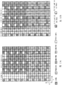
图4是用于说明本发明的无线通信方法的第一方法-1的图。FIG. 4 is a diagram for explaining the first method-1 of the wireless communication method of the present invention.
图5是用于说明本发明的无线通信方法的第一方法-1的图。FIG. 5 is a diagram for explaining the first method-1 of the wireless communication method of the present invention.
图6是用于说明本发明的无线通信方法的第一方法-2的图。FIG. 6 is a diagram for explaining the first method-2 of the wireless communication method of the present invention.
图7是用于说明本发明的无线通信方法的第一方法-2的图。FIG. 7 is a diagram for explaining the first method-2 of the wireless communication method of the present invention.
图8是用于说明本发明的无线通信方法的第二方法-1的图。FIG. 8 is a diagram for explaining the second method-1 of the wireless communication method of the present invention.
图9是用于说明本发明的无线通信方法的第二方法-1的图。FIG. 9 is a diagram for explaining the second method-1 of the wireless communication method of the present invention.
图10是用于说明本发明的无线通信方法的第二方法-2的图。FIG. 10 is a diagram for explaining the second method-2 of the wireless communication method of the present invention.
图11是用于说明本发明的无线通信方法的第二方法-2的图。FIG. 11 is a diagram for explaining the second method-2 of the wireless communication method of the present invention.
图12是用于说明本发明的无线通信方法的第三方法-1的图。FIG. 12 is a diagram for explaining a third method-1 of the wireless communication method of the present invention.
图13是用于说明本发明的无线通信方法的第三方法-2的图。FIG. 13 is a diagram for explaining a third method-2 of the wireless communication method of the present invention.
图14是用于说明本发明的无线通信方法的第四方法-1以及第四方法-2的图。FIG. 14 is a diagram for explaining fourth method-1 and fourth method-2 of the wireless communication method of the present invention.
图15是用于说明JP-CoMP中的PDCCH长的影响的图。FIG. 15 is a diagram for explaining the influence of the PDCCH length in JP-CoMP.
图16是用于说明本发明的无线通信方法的第五方法的图。FIG. 16 is a diagram for explaining a fifth method of the wireless communication method of the present invention.
图17是用于说明本发明的无线通信方法的第五方法的图。FIG. 17 is a diagram for explaining a fifth method of the wireless communication method of the present invention.
图18是用于说明无线通信系统的结构的图。FIG. 18 is a diagram for explaining the configuration of a wireless communication system.
图19是无线基站装置的整体结构的说明图。FIG. 19 is an explanatory diagram of the overall configuration of a radio base station apparatus.
图20是无线基站装置的对应于本发明的无线通信方法的功能方框图。Fig. 20 is a functional block diagram of a radio base station apparatus corresponding to the radio communication method of the present invention.
图21是移动终端装置的整体结构的说明图。FIG. 21 is an explanatory diagram of the overall configuration of the mobile terminal device.
图22是移动终端装置的对应于本发明的无线通信方法的功能方框图。FIG. 22 is a functional block diagram of a mobile terminal device corresponding to the wireless communication method of the present invention.
具体实施方式Detailed ways
首先,说明下行链路的CoMP发送。作为下行链路的CoMP发送,有协作调度(Coordinated scheduling)/协作波束成型(Coordinated beamforming)(CS/CB)和联合处理(Joint processing)。协作调度/协作波束成型是对1个UE仅从1个小区进行发送的方法,且是考虑来自其他小区的干扰和对于其他小区的干扰而进行频率/空间区域中的无线资源的分配的方法。另一方面,联合处理是应用预编码的多个小区同时发送,有如图1A所示的对1个UE从多个小区进行发送的联合传输(Joint transmission)和如图1B所示的瞬间选择小区的动态小区选择(Dynamic Cell Selection)。First, downlink CoMP transmission will be described. As downlink CoMP transmission, there are coordinated scheduling (Coordinated scheduling)/coordinated beamforming (Coordinated beamforming) (CS/CB) and joint processing (Joint processing). Coordinated scheduling/coordinated beamforming is a method of transmitting from only one cell to one UE, and is a method of allocating radio resources in a frequency/spatial region in consideration of interference from and to other cells. On the other hand, joint processing is the simultaneous transmission of multiple cells with precoding applied. There are joint transmission (Joint transmission) for one UE to transmit from multiple cells as shown in Figure 1A and instant cell selection as shown in Figure 1B Dynamic Cell Selection.
作为实现CoMP发送的结构,有包含无线基站装置eNB和通过光伸展结构(光纤)与该无线基站装置eNB连接的多个远程无线装置(RRE:RemoteRadio Equipment,射频拉远设备)的结构(基于远程无线装置结构的集中控制)。除此之外,有无线基站装置eNB的结构(基于独立基站结构的自主分散控制)。在本发明中,可以应用于上述任一个结构。As a structure for implementing CoMP transmission, there is a structure including a wireless base station device eNB and a plurality of remote wireless devices (RRE: Remote Radio Equipment) connected to the wireless base station device eNB through an optical extension structure (optical fiber) (based on remote centralized control of wireless device structures). In addition, there is a structure of a wireless base station device eNB (autonomous distributed control based on a structure of an independent base station). In the present invention, any of the above structures can be applied.
在集中控制中,通过无线基站装置eNB集中控制远程无线装置。在RRE结构中,由于进行多个RRE的基带信号处理以及控制的无线基站装置eNB(集中基站)和各小区即RRE之间通过使用了光纤的基带信号连接,所以在集中基站中能够统一进行小区间的无线资源控制。另一方面,在自主分散控制中,在多个无线基站装置eNB(或者RRE)中分别进行调度等的无线资源分配控制。此时,通过利用无线基站装置间的X2接口,根据需要而将定时信息或调度等的无线资源分配信息发送到其中一个无线基站装置,进行小区间的协作。In centralized control, remote wireless devices are centrally controlled by a wireless base station device eNB. In the RRE structure, since the radio base station device eNB (centralized base station) that performs baseband signal processing and control of multiple RREs is connected to each cell, that is, the RRE, through a baseband signal connection using an optical fiber, the centralized base station can uniformly perform cell control. radio resource control. On the other hand, in autonomous distributed control, radio resource allocation control such as scheduling is performed in each of a plurality of radio base station apparatuses eNB (or RRE). At this time, by using the X2 interface between the radio base station apparatuses, radio resource allocation information such as timing information and scheduling is transmitted to one of the radio base station apparatuses as necessary, and inter-cell cooperation is performed.
如上所述,由于CRS或PDCCH存在分别按每个小区复用到不同的位置的情况,所以认为在应用JP-CoMP时,在移动终端装置中,不能准确地解调数据信号。As described above, since CRS and PDCCH may be multiplexed in different positions for each cell, it is considered that when JP-CoMP is applied, data signals cannot be accurately demodulated in mobile terminal apparatuses.
例如,使用图2说明CRS。在应用JT-CoMP的情况下,从多个小区、例如从图2A所示的小区#A以及图2B所示的小区#B(在这里,小区#A为服务小区、小区#B为协作小区(邻接小区))对同一个移动终端装置进行数据发送。在应用这样的JT-CoMP的情况下,如图2A、图2B所示,在CRS的复用位置分别不同时,存在CRS与数据信号发生冲突而在移动终端装置中不能准确地接收CRS的可能性。For example, CRS will be described using FIG. 2 . In the case of applying JT-CoMP, multiple cells, for example, cell #A shown in FIG. 2A and cell #B shown in FIG. (adjacent cell)) to transmit data to the same mobile terminal device. When such JT-CoMP is applied, as shown in FIG. 2A and FIG. 2B , when the multiplexing positions of the CRS are different, there is a possibility that the CRS and the data signal collide, and the mobile terminal device may not be able to receive the CRS accurately. sex.
因此,在应用JT-CoMP的情况下,为了使得在移动终端装置中CRS不会与数据信号发生冲突,需要将服务小区以外的小区(邻接小区(可成为协作小区的邻接小区))的CRS的复用位置通知到移动终端装置。因此,服务小区的无线基站装置将服务小区以外的小区的CRS的复用位置作为解调用信息而通知到移动终端装置。Therefore, when JT-CoMP is applied, in order to prevent the CRS from colliding with the data signal in the mobile terminal device, it is necessary to set the CRS of the cell other than the serving cell (adjacent cell (adjacent cell that can be a cooperative cell)) Multiplex the location notification to the mobile terminal device. Therefore, the radio base station apparatus of the serving cell notifies the mobile terminal apparatus of the multiplexing position of the CRS of a cell other than the serving cell as information for demodulation.
在图2所示的情况下,小区#A的无线基站装置对移动终端装置通知作为邻接小区的小区#B的CRS的复用位置的信息。在移动终端装置中,在小区#B的CRS的复用位置中没有复用数据信号,使得小区#A的数据信号不会发生冲突。因此,小区#B的CRS的复用位置意味着小区#A的PDSCH的静默图案。另外,能够从小区ID算出偏移量,根据该偏移量求出邻接小区的CRS的复用位置。因此,在本发明的第一方式中,为了使得在移动终端装置中CRS不会与数据信号发生冲突,将服务小区的PDSCH的静默图案通知到移动终端装置。在服务小区为小区#A的情况下,将图2A所示的PDSCH静默的图案(小区#B的CRS的复用位置)通知到移动终端装置,在服务小区为小区#B的情况下,将图2B所示的PDSCH静默的图案(小区#A的CRS的复用位置)通知到移动终端装置。In the case shown in FIG. 2 , the radio base station apparatus of the cell #A notifies the mobile terminal apparatus of information on the multiplexing position of the CRS of the cell #B which is an adjacent cell. In the mobile terminal apparatus, no data signal is multiplexed in the multiplexing position of the CRS of the cell #B, so that the data signal of the cell #A does not collide. Therefore, the multiplexing position of the CRS of the cell #B means the muting pattern of the PDSCH of the cell #A. In addition, an offset can be calculated from the cell ID, and the multiplexing position of the CRS of the adjacent cell can be obtained from the offset. Therefore, in the first aspect of the present invention, the mobile terminal device is notified of the muting pattern of the PDSCH of the serving cell so that the CRS does not collide with the data signal in the mobile terminal device. When the serving cell is cell #A, the PDSCH muting pattern (multiplexing position of the CRS of cell #B) shown in FIG. 2A is notified to the mobile terminal device, and when the serving cell is cell #B, the The PDSCH muting pattern (multiplexing position of the CRS of the cell #A) shown in FIG. 2B is notified to the mobile terminal apparatus.
另一方面,在应用DCS-CoMP的情况下,从多个小区中的其中一个小区、例如从图3A所示的小区#A以及图3B所示的小区#B中的其中一个小区对同一个移动终端装置进行数据发送。由此,在应用DCS-CoMP的情况下,从单一小区进行数据发送。此时,不需要如JT-CoMP那样对PDSCH进行静默(无发送)(图3A、图3B),取而代之,需要对移动终端装置通知CoMP小区(存在应用CoMP发送的可能性的小区)的CRS复用位置。即,在应用DCS-CoMP的情况下,需要对移动终端装置通知服务小区以外的CoMP小区的CRS的复用位置(CRS复用图案)。On the other hand, when DCS-CoMP is applied, one of the cells, for example, one of the cell #A shown in FIG. 3A and the cell #B shown in FIG. The mobile terminal device transmits data. Thus, when DCS-CoMP is applied, data transmission is performed from a single cell. In this case, it is not necessary to mute the PDSCH (no transmission) as in JT-CoMP (FIG. 3A, FIG. 3B). Use location. That is, when DCS-CoMP is applied, it is necessary to notify the mobile terminal apparatus of the CRS multiplexing position (CRS multiplexing pattern) of the CoMP cell other than the serving cell.
关于该图案信息(PDSCH静默图案或者CRS复用图案)的通知方法,举出以下的四种(第一方法~第四方法)。Regarding the reporting method of the pattern information (PDSCH muting pattern or CRS multiplexing pattern), the following four methods (first method to fourth method) are given.
(第一方法-1)(first method-1)
这个方法是将表示副载波位置的位图作为静默图案而通知的方法。在这个方法中,将位图信息包含在DCI(Downlink Control Information,下行链路控制信息)中动态地通知。移动终端装置具有图4所示的表(在DCI中包含的位图信息和静默图案相关联的表),从通过DCI而通知到的位图信息识别静默图案,使用静默图案以外的资源来解调数据信号。This method is a method of notifying a bitmap indicating subcarrier positions as a muting pattern. In this method, the bitmap information is included in DCI (Downlink Control Information, downlink control information) to dynamically notify. The mobile terminal device has the table shown in FIG. 4 (the table for associating the bitmap information included in the DCI with the muting pattern), recognizes the muting pattern from the bitmap information notified by the DCI, and uses resources other than the muting pattern to solve the problem. Adjust the data signal.
图4所示的表是在DCI中包含的位图信息和静默图案相关联的表,位图“00000”为「无静默」、位图“00001”为「仅服务小区的偏移+1」、位图“00010”为「仅服务小区的偏移+2」、位图“00100”为「仅服务小区的偏移+3」、位图“11111”为「服务小区的偏移+1/+2/+3/+4/+5」。该位图表示图5所示的副载波位置。在图5中,服务小区表示小区ID#0的静默图案,「服务小区的偏移+1」表示小区ID#1的静默图案,「服务小区的偏移+2」表示小区ID#2的静默图案,「服务小区的偏移+3」表示小区ID#3的静默图案。The table shown in FIG. 4 is a table in which the bitmap information included in the DCI is associated with the muting pattern, and the bitmap "00000" is "no muting", the bitmap "00001" is "only the offset of the serving cell + 1", Bitmap "00010" is "only the offset of the serving cell + 2", bitmap "00100" is "only the offset of the serving cell + 3", and bitmap "11111" is "the offset of the serving cell +1/+2/+3/ +4/+5". This bitmap represents the subcarrier positions shown in FIG. 5 . In FIG. 5 , the serving cell represents the muting pattern of
另外,图4所示的表是一例,并不限定于此。此外,图4以及图5表示1个天线的情况,但这个方法也能够应用于2个天线以上的情况。In addition, the table shown in FIG. 4 is an example, and is not limited to this. 4 and 5 show the case of one antenna, but this method can also be applied to the case of two or more antennas.
(第一方法-2)(first method-2)
这个方法是将表示副载波位置的位图作为CRS复用图案而通知的方法。在这个方法中,将位图信息包含在DCI(Downlink Control Information,下行链路控制信息)中动态地通知。移动终端装置具有图6所示的表(在DCI中包含的位图信息和CRS复用图案相关联的表),从通过DCI而通知到的位图信息识别CRS复用图案,使用CRS复用位置以外的资源来解调数据信号。This method is a method of notifying a bitmap indicating subcarrier positions as a CRS multiplexing pattern. In this method, the bitmap information is included in DCI (Downlink Control Information, downlink control information) to dynamically notify. The mobile terminal device has the table shown in FIG. 6 (the table in which the bitmap information included in the DCI is associated with the CRS multiplexing pattern), recognizes the CRS multiplexing pattern from the bitmap information notified by the DCI, and uses the CRS multiplexing pattern. resources outside the location to demodulate the data signal.
图6所示的表是在DCI中包含的位图信息和CRS复用图案相关联的表,位图“00000”为「与服务小区相同」、位图“00001”为「仅服务小区的偏移+1」、位图“00010”为「仅服务小区的偏移+2」、位图“00100”为「仅服务小区的偏移+3」、位图“11111”为「服务小区的偏移+1/+2/+3/+4/+5」。该位图表示图7所示的副载波位置。在图7中,服务小区表示小区ID#0的CRS复用图案,「服务小区的偏移+1」表示小区ID#1的CRS复用图案,「服务小区的偏移+2」表示小区ID#2的CRS复用图案,「服务小区的偏移+3」表示小区ID#3的CRS复用图案。The table shown in FIG. 6 is a table that correlates the bitmap information included in the DCI and the CRS multiplexing pattern. The bitmap "00000" is "same as the serving cell", and the bitmap "00001" is "offset of the serving cell only". shift +1", bitmap "00010" is "offset of serving cell only +2", bitmap "00100" is "offset of serving cell only +3", bitmap "11111" is "offset of serving cell +1/ +2/+3/+4/+5". This bitmap represents the subcarrier positions shown in FIG. 7 . In Fig. 7, the serving cell represents the CRS multiplexing pattern of
另外,图6所示的表是一例,并不限定于此。此外,图6以及图7表示1个天线的情况,但这个方法也能够应用于2个天线以上的情况。In addition, the table shown in FIG. 6 is an example, and is not limited to this. 6 and 7 show the case of one antenna, but this method can also be applied to the case of two or more antennas.
(第二方法-1)(Second method - 1)
这个方法是将表示静默图案的下行控制信息作为静默图案而通知的方法。在这个方法中,将表示静默图案的比特包含在DCI中动态地通知。此时,下行控制信息和静默图案相关联。移动终端装置具有图8所示的表(在DCI中包含的比特和静默图案相关联的表),从通过DCI而通知到的比特识别静默图案,使用静默图案以外的资源来解调数据信号。This method is a method of notifying downlink control information indicating a muting pattern as a muting pattern. In this method, it is dynamically notified that a bit representing a silence pattern is included in the DCI. At this time, the downlink control information is associated with the silence pattern. The mobile terminal apparatus has the table shown in FIG. 8 (a table associating bits included in the DCI with muting patterns), recognizes the muting pattern from the bits notified by the DCI, and demodulates the data signal using resources other than the muting pattern.
图8所示的表是在DCI中包含的比特和静默图案相关联的表,比特“00”为「无静默」、比特“01”为「仅服务小区的偏移+1」、比特“10”为「仅服务小区的偏移+2」、比特“11”为「服务小区的偏移+1/+2」。例如,比特“01”表示图2A的静默图案,比特“11”表示图9的静默图案。另外,图8所示的表为一例,并不限定于此。The table shown in FIG. 8 is a table in which the bits included in the DCI are associated with the muting pattern, and the bit "00" is "no muting", the bit "01" is "only the offset of the serving cell + 1", and the bit "10" It is "only the offset of the serving cell + 2", and the bit "11" is "the offset of the serving cell + 1/+2". For example, bit "01" represents the mute pattern of FIG. 2A, and bit "11" represents the mute pattern of FIG. In addition, the table shown in FIG. 8 is an example, and is not limited to this.
(第二方法-2)(second method-2)
这个方法是将表示CRS复用图案的下行控制信息作为CRS复用图案而通知的方法。在这个方法中,将表示CRS复用图案的比特包含在DCI中动态地通知。此时,下行控制信息和CRS复用图案相关联。移动终端装置具有图10所示的表(在DCI中包含的比特和CRS复用图案相关联的表),从通过DCI而通知到的比特识别CRS复用图案,使用CRS复用位置以外的资源来解调数据信号。This method is a method of notifying downlink control information indicating a CRS multiplexing pattern as a CRS multiplexing pattern. In this method, the bits indicating the CRS multiplexing pattern are included in the DCI to be dynamically notified. At this time, the downlink control information is associated with the CRS multiplexing pattern. The mobile terminal device has the table shown in FIG. 10 (the table in which the bits included in the DCI are associated with the CRS multiplexing pattern), recognizes the CRS multiplexing pattern from the bits notified by the DCI, and uses resources other than the CRS multiplexing position to demodulate the data signal.
图10所示的表是在DCI中包含的比特和CRS复用图案相关联的表,比特“000”为「与服务小区相同」、比特“001”为「仅服务小区的偏移+1」、比特“010”为「仅服务小区的偏移+2」、比特“011”为「仅服务小区的偏移+3」、比特“100”为「仅服务小区的偏移+4」、比特“101”为「仅服务小区的偏移+5」。例如,比特“001”表示图3B的CRS复用图案,比特“010”表示图11的CRS复用图案。另外,图10所示的表为一例,并不限定于此。The table shown in FIG. 10 is a table in which the bits included in the DCI are associated with the CRS multiplexing pattern. Bit "000" is "same as the serving cell", bit "001" is "only the offset of the serving cell + 1", Bit "010" is "offset of serving cell only + 2", bit "011" is "offset of serving cell only + 3", bit "100" is "offset of serving cell only + 4", bit "101" is "Only the offset of the serving cell + 5". For example, bit "001" represents the CRS multiplexing pattern of FIG. 3B , and bit "010" represents the CRS multiplexing pattern of FIG. 11 . In addition, the table shown in FIG. 10 is an example, and is not limited to this.
(第三方法-1)(third method-1)
这个方法是由通过高层信令而发送的CoMP小区的小区识别信息和与该CoMP小区的信息(与要静默的小区有关的信息)对应的下行控制信息而通知静默图案的方法。此时,下行控制信息和CoMP小区的信息相关联。移动终端装置具有图12所示的表(在DCI中包含的比特和CoMP小区的信息相关联的表),根据来自通过DCI而通知的比特的CoMP小区的信息,和通过高层信令而通知的CoMP小区的小区识别信息(小区ID)求出静默图案,并使用静默图案以外的资源来解调数据信号。This method is a method of notifying a muting pattern by means of cell identification information of a CoMP cell and downlink control information corresponding to information of the CoMP cell (information about a cell to be muted) transmitted by higher layer signaling. At this time, the downlink control information is associated with the information of the CoMP cell. The mobile terminal apparatus has the table shown in FIG. 12 (the table in which the bits included in the DCI are associated with the information of the CoMP cell), the information of the CoMP cell from the bits notified by the DCI, and the information notified by higher layer signaling. The muting pattern is obtained from the cell identification information (cell ID) of the CoMP cell, and the data signal is demodulated using resources other than the muting pattern.
在这个方法中,无线基站装置通过高层信令将CoMP小区(存在应用CoMP发送的可能性的小区)的小区ID通知到移动终端装置。例如,无线基站装置在CoMP小区为小区#A、小区#B的情况下,将小区#A的小区ID7号和小区#B的小区ID8号通知到移动终端装置。另一方面,无线基站装置通过DCI将CoMP小区的信息通知到移动终端装置。例如,无线基站装置作为CoMP小区的信息,将表示「仅CoMP小区#B的偏移」的DCI的比特“10”通知到移动终端装置。在移动终端装置中,根据小区ID号和CoMP小区的信息而求出静默图案。即,计算小区#B的小区ID号的Mod6而算出偏移量2(剩余运算),由此求出静默图案(服务小区的偏移+2)。另外,图12所示的表和小区ID号为一例,并不限定于此。In this method, the radio base station apparatus notifies the mobile terminal apparatus of the cell ID of the CoMP cell (the cell to which CoMP transmission may be applied) by high-layer signaling. For example, when the CoMP cells are cell #A and cell #B, the radio base station apparatus notifies the mobile terminal apparatus of cell ID 7 of cell #A and cell ID 8 of cell #B. On the other hand, the radio base station apparatus notifies the mobile terminal apparatus of CoMP cell information through DCI. For example, the radio base station apparatus notifies the mobile terminal apparatus of bit “10” of DCI indicating “offset of CoMP cell #B only” as CoMP cell information. In the mobile terminal device, the muting pattern is obtained from the cell ID number and the information of the CoMP cell. That is, Mod6 of the cell ID number of the cell #B is calculated to calculate an offset of 2 (residual calculation), thereby obtaining a muting pattern (offset of the serving cell+2). In addition, the table and the cell ID numbers shown in FIG. 12 are examples and are not limited thereto.
(第三方法-2)(third method-2)
这个方法是由通过高层信令而发送的CoMP小区的小区识别信息和与该CoMP小区的信息(与CRS复用图案的小区有关的信息)对应的下行控制信息而通知CRS复用图案的方法。此时,下行控制信息和CoMP小区的信息相关联。移动终端装置具有图13所示的表(在DCI中包含的比特和CoMP小区的信息相关联的表),根据来自通过DCI而通知的比特的CoMP小区的信息,和通过高层信令而通知的CoMP小区的小区识别信息(小区ID)求出CRS复用图案,并使用CRS复用位置以外的资源来解调数据信号。This method is a method of notifying the CRS multiplexing pattern by the cell identification information of the CoMP cell and the downlink control information corresponding to the information of the CoMP cell (information about the cell of the CRS multiplexing pattern) transmitted by higher layer signaling. At this time, the downlink control information is associated with the information of the CoMP cell. The mobile terminal apparatus has the table shown in FIG. 13 (the table in which the bits included in the DCI are associated with the information of the CoMP cell), and the information of the CoMP cell from the bits notified by the DCI and the information notified by higher layer signaling The CRS multiplexing pattern is obtained from the cell identification information (cell ID) of the CoMP cell, and the data signal is demodulated using resources other than the CRS multiplexing positions.
在这个方法中,无线基站装置通过高层信令将CoMP小区(存在应用CoMP发送的可能性的小区)的小区ID通知到移动终端装置。例如,无线基站装置在CoMP小区为小区#A、小区#B的情况下,将小区#A的小区ID7号和小区#B的小区ID8号通知到移动终端装置。另一方面,无线基站装置通过DCI将CoMP小区的信息通知到移动终端装置。例如,无线基站装置作为CoMP小区的信息,将表示「仅CoMP小区#B的偏移」的DCI的比特“10”通知到移动终端装置。在移动终端装置中,根据小区ID号和CoMP小区的信息而求出CRS复用图案。即,计算小区#B的小区ID号的Mod6而算出偏移量2(剩余运算),由此求出CRS复用图案(服务小区的偏移+2)。另外,图13所示的表和小区ID号为一例,并不限定于此。In this method, the radio base station apparatus notifies the mobile terminal apparatus of the cell ID of the CoMP cell (the cell to which CoMP transmission may be applied) by high-layer signaling. For example, when the CoMP cells are cell #A and cell #B, the radio base station apparatus notifies the mobile terminal apparatus of cell ID 7 of cell #A and cell ID 8 of cell #B. On the other hand, the radio base station apparatus notifies the mobile terminal apparatus of CoMP cell information through DCI. For example, the radio base station apparatus notifies the mobile terminal apparatus of bit “10” of DCI indicating “offset of CoMP cell #B only” as CoMP cell information. In the mobile terminal apparatus, the CRS multiplexing pattern is obtained from the cell ID number and the information of the CoMP cell. That is, Mod6 of the cell ID number of the cell #B is calculated to calculate an offset of 2 (residual calculation), thereby obtaining a CRS multiplexing pattern (offset of the serving cell + 2). In addition, the table and the cell ID numbers shown in FIG. 13 are examples and are not limited thereto.
(第四方法-1)(fourth method-1)
这个方法是通过高层信令(例如,RRC信令)而通知静默图案的方法。在这个方法中,将静默图案半静态地进行通知。通过高层信令而通知的静默图案既可以是在上述第一方法中使用的位图信息,也可以是在上述第二方法中使用的比特信息。This method is a method of notifying a muting pattern through higher layer signaling (for example, RRC signaling). In this method, the silence pattern is notified semi-statically. The muting pattern notified by high layer signaling may be the bitmap information used in the above-mentioned first method, or may be the bit information used in the above-mentioned second method.
在这个方法中,也可以对静默图案进行静态化。在对静默图案进行静态化的情况下,如图15所示,关于在PDSCH区域中CRS被复用的码元(X),不对进行CoMP接收的移动终端装置分配数据信号。即,对于进行CoMP接收的移动终端装置,在CoMP小区中CRS被复用的全部的码元(X)的图案成为静默图案。In this method, the silence pattern can also be staticized. When the muting pattern is made static, as shown in FIG. 15 , no data signal is assigned to a mobile terminal device performing CoMP reception with respect to the symbol (X) in which the CRS is multiplexed in the PDSCH region. That is, for a mobile terminal apparatus performing CoMP reception, the pattern of all symbols (X) in which CRSs are multiplexed in the CoMP cell becomes a muting pattern.
(第四方法-2)(fourth method-2)
这个方法是通过高层信令(例如,RRC信令)而通知CRS复用图案的方法。在这个方法中,将CRS复用图案半静态地进行通知。通过高层信令而通知的CRS复用图案既可以是在上述第一方法-2中使用的位图信息,也可以是在上述第二方法-2中使用的比特信息。This method is a method of notifying a CRS multiplexing pattern through higher layer signaling (for example, RRC signaling). In this method, the CRS multiplexing pattern is notified semi-statically. The CRS multiplexing pattern notified by higher layer signaling may be the bitmap information used in the above-mentioned first method-2, or the bit information used in the above-mentioned second method-2.
在这个方法中,也可以对CRS复用图案进行静态化。在对CRS复用图案进行静态化的情况下,如图14所示,关于在PDSCH区域中CRS被复用的码元(X),不对进行CoMP接收的移动终端装置分配数据信号。即,对于进行CoMP接收的移动终端装置,在CoMP小区中CRS被复用的全部的码元(X)的图案成为CRS复用图案。In this method, the CRS multiplexing pattern can also be made static. When the CRS multiplexing pattern is made static, as shown in FIG. 14 , no data signal is assigned to the mobile terminal apparatus performing CoMP reception with respect to the symbol (X) on which the CRS is multiplexed in the PDSCH region. That is, for a mobile terminal apparatus performing CoMP reception, a pattern of all symbols (X) in which CRSs are multiplexed in a CoMP cell becomes a CRS multiplexing pattern.
与CRS相同地,由于PDCCH存在分别按每个小区复用到不同的位置的情况,所以在应用JP-CoMP时,认为在移动终端装置中不能准确地解调数据信号。Similar to CRS, since PDCCHs may be multiplexed in different positions for each cell, it is considered that data signals cannot be accurately demodulated in mobile terminal apparatuses when JP-CoMP is applied.
由于PDCCH信号复用到子帧的开头1个OFDM码元到3个OFDM码元,所以考虑如图15所示那样服务小区(小区#A:图15A)的PDCCH码元长与邻接小区(小区#B:图15B)的PDCCH码元长不同的情况。此时,若应用JP-CoMP,则需要配合PDCCH码元长长的小区,对进行CoMP接收的移动终端装置进行数据发送。例如,在应用JP-CoMP的情况下,如图15所示,在服务小区的PDCCH长比邻接小区的PDCCH长短的情况下,需要对进行CoMP接收的移动终端装置通知服务小区以外的小区的PDCCH长。因此,服务小区的无线基站装置将服务小区以外的小区的PDCCH长作为解调用信息而通知到移动终端装置。另外,在移动终端装置中,在接受到PDCCH长的信息时,由于从PDCCH长+1个OFDM码元起复用PDSCH,所以也可以代替PDCCH长而将PDSCH的复用开始位置作为解调用信息。Since the PDCCH signal is multiplexed to the first 1 OFDM symbol to 3 OFDM symbols of the subframe, consider the relationship between the PDCCH symbol length of the serving cell (cell #A: Fig. 15A ) and the adjacent cell (cell #B: A case where the PDCCH symbol lengths in FIG. 15B) are different. At this time, if JP-CoMP is applied, it is necessary to transmit data to a mobile terminal apparatus that performs CoMP reception in accordance with a cell with a long PDCCH symbol. For example, when JP-CoMP is applied, as shown in FIG. 15 , when the PDCCH length of the serving cell is shorter than the PDCCH length of the neighboring cell, it is necessary to notify the PDCCH of the cell other than the serving cell to the mobile terminal device performing CoMP reception. long. Therefore, the radio base station apparatus of the serving cell notifies the mobile terminal apparatus of the PDCCH lengths of cells other than the serving cell as information for demodulation. In addition, in the mobile terminal apparatus, when receiving the information of the PDCCH length, since the PDSCH is multiplexed from the PDCCH length + 1 OFDM symbol, the multiplexing start position of the PDSCH may be used as the information for demodulation instead of the PDCCH length. .
关于该PDSCH的复用开始位置的信息的通知方法,举出以下的两种(第五方法、第六方法)。The following two methods (fifth method and sixth method) are exemplified as the notification method of the information on the multiplexing start position of the PDSCH.
(第五方法)(fifth method)
这个方法是通知表示PDSCH的复用开始位置的下行控制信息的方法。在这个方法中,将表示PDSCH的复用开始位置的比特包含在DCI中动态地通知。此时,下行控制信息和PDSCH的复用开始位置相关联。移动终端装置具有图16所示的表(在DCI中包含的比特和PDSCH的复用开始位置相关联的表),根据通过DCI而通知的比特识别PDSCH的复用开始位置,并根据该复用开始位置来解调数据信号。This method is a method of notifying downlink control information indicating the multiplexing start position of the PDSCH. In this method, the bit indicating the multiplexing start position of the PDSCH is included in the DCI and dynamically notified. At this time, the downlink control information is associated with the multiplexing start position of the PDSCH. The mobile terminal device has the table shown in FIG. 16 (the table in which the bits included in the DCI are associated with the multiplexing start position of the PDSCH), recognizes the multiplexing start position of the PDSCH from the bit notified by the DCI, and The starting position to demodulate the data signal.
图16所示的表是在DCI中包含的比特和PDSCH的复用开始位置相关联的表,比特“00”为「第1码元」、比特“01”为「第2码元」、比特“10”为「第3码元」、比特“11”为「第4码元」。例如,比特“10”表示图17的PDSCH的复用开始位置(第3码元)。另外,图16所示的表为一例,并不限定于此。The table shown in FIG. 16 is a table in which the bits included in the DCI are associated with the multiplexing start position of the PDSCH, and the bit "00" is the "first symbol", the bit "01" is the "second symbol", and the bit "10" is the "third symbol", and the bit "11" is the "fourth symbol". For example, bit "10" indicates the multiplexing start position (third symbol) of the PDSCH in FIG. 17 . In addition, the table shown in FIG. 16 is an example, and is not limited to this.
(第六方法)(sixth method)
这个方法是通过高层信令(例如,RRC信令)而通知PDSCH的复用开始位置的方法。在这个方法中,将PDSCH的复用开始位置半静态地进行通知。通过高层信令而通知的PDSCH的复用开始位置也可以是在上述第五方法中使用的比特信息。This method is a method of notifying the multiplexing start position of the PDSCH through higher layer signaling (for example, RRC signaling). In this method, the multiplexing start position of the PDSCH is notified semi-statically. The multiplexing start position of the PDSCH notified by higher layer signaling may be the bit information used in the above-mentioned fifth method.
在这个方法中,也可以对PDSCH的复用开始位置进行静态化。在对PDSCH的复用开始位置进行静态化的情况下,始终固定复用开始位置(例如,第4码元)。In this method, it is also possible to staticize the multiplexing start position of the PDSCH. When the multiplexing start position of the PDSCH is static, the multiplexing start position (for example, the fourth symbol) is always fixed.
另外,关于通知PDSCH的复用开始位置的情况,无线基站装置判断服务小区的PDCCH长是否比邻接小区的PDCCH长短,在服务小区的PDCCH长比邻接小区的PDCCH长短时,考虑邻接小区的PDCCH长而决定PDSCH的复用开始位置,并将该复用开始位置通知到移动终端装置。例如,无线基站装置在服务小区的PDCCH长比邻接小区的PDCCH长短时,将在邻接小区的PDCCH长中最长的PDCCH长+1个码元设为PDSCH的复用开始位置。因此,在PDCCH长最大为3个码元的情况下,PDSCH的复用开始位置最大成为4个码元。In addition, when notifying the multiplexing start position of the PDSCH, the radio base station apparatus judges whether the PDCCH length of the serving cell is shorter than the PDCCH length of the neighboring cell, and considers the PDCCH length of the neighboring cell when the PDCCH length of the serving cell is shorter than the PDCCH length of the neighboring cell. Then, the multiplexing start position of the PDSCH is determined, and the multiplexing start position is notified to the mobile terminal device. For example, when the PDCCH length of the serving cell is shorter than the PDCCH length of the neighboring cell, the radio base station apparatus sets the longest PDCCH length+1 symbol among the PDCCH lengths of the neighboring cell as the multiplexing start position of the PDSCH. Therefore, when the PDCCH length is a maximum of 3 symbols, the multiplexing start position of a PDSCH is a maximum of 4 symbols.
如上所述,解调用信息是用于支持移动终端装置中的数据信号的解调的信息,在以避免CRS和数据信号的冲突作为目的的情况下,是与服务小区以外的小区的CRS的复用位置有关的信息。此外,在以容许PDCCH的码元长的差异作为目的的情况下,解调用信息是与PDCCH的码元长或者PDSCH的复用开始位置有关的信息。另外,在以双方作为目的的情况下,解调用信息是与服务小区以外的小区的CRS的复用位置有关的信息、以及是与PDCCH的码元长或者PDSCH的复用开始位置有关的信息是理所当然的。As described above, the information for demodulation is information for supporting the demodulation of the data signal in the mobile terminal apparatus, and when the purpose is to avoid the collision between the CRS and the data signal, it is information related to the CRS of a cell other than the serving cell. Information about the reuse position. Also, when the purpose is to allow a difference in the PDCCH symbol length, the information for demodulation is information on the PDCCH symbol length or the multiplexing start position of the PDSCH. In addition, when both are targeted, the information for demodulation is information on the multiplexing position of the CRS of a cell other than the serving cell, and information on the symbol length of the PDCCH or the multiplexing start position of the PDSCH. It is a matter of course.
由此,在本发明中,由于在应用协作多点发送时,将移动终端装置中的数据信号的解调用信息发送到进行协作多点接收的移动终端装置,在移动终端装置中,使用解调用信息对进行了协作多点接收的数据信号进行解调,所以在应用协作多点发送、尤其是JP-CoMP的情况下,在移动终端装置中能够准确地解调数据信号。Therefore, in the present invention, since the demodulation information of the data signal in the mobile terminal device is transmitted to the mobile terminal device performing coordinated multi-point reception when CoMP transmission is applied, in the mobile terminal device, the demodulation information is used in the mobile terminal device. Since the call information demodulates the data signal that has undergone coordinated multi-point reception, when the coordinated multi-point transmission, especially JP-CoMP, is applied, the data signal can be accurately demodulated in the mobile terminal device.
以下,参照附图详细说明本发明的实施方式。在这里,说明使用与LTE-A系统对应的无线基站装置以及移动终端装置的情况。Hereinafter, embodiments of the present invention will be described in detail with reference to the drawings. Here, a case where a radio base station device and a mobile terminal device compatible with the LTE-A system are used will be described.
参照图18,说明具有本发明的一实施方式的移动终端装置(UE:UserEquipment)10以及无线基站装置(eNodeB)20的无线通信系统1。图18是用于说明具有本发明的移动终端装置10以及无线基站装置20的无线通信系统1的结构的图。另外,图18所示的无线通信系统1例如是LTE系统或者包含SUPER3G的系统。此外,该移动通信系统1既可以被称为IMT-Advanced,也可以被称为4G。Referring to FIG. 18 , a
如图18所示,无线通信系统1包含无线基站装置20A、20B、以及与该无线基站装置20A、20B进行通信的多个移动终端装置10A、10B。无线基站装置20A、20B分别与上位站装置30连接,该上位站装置30与核心网络40连接。移动终端装置10A、10B在小区C1中与无线基站装置20A进行通信,在小区C2中与无线基站装置20B进行通信。另外,上位站装置30例如包含接入网关装置、无线网络控制器(RNC)、移动性管理实体(MME)等,但并不限定于此。As shown in FIG. 18 , the
由于各移动终端装置(10A、10B)具有相同的结构、功能、状态,所以以下在没有特别说明的情况下以移动终端装置10进行说明。此外,为了便于说明,设为与无线基站装置20A、20B进行无线通信的是移动终端装置10而进行说明,但更一般地,可以是包括移动终端装置和固定终端装置的用户装置(UE)。Since each mobile terminal device ( 10A, 10B) has the same configuration, function, and state, the mobile
在无线通信系统1中,作为无线接入方式,对于下行链路应用OFDMA(正交频分复用),对上行链路应用SC-FDMA(单载波-频分复用)。OFDMA是将频带分割为多个窄的频带(副载波),对各副载波映射数据后进行通信的多载波传输方式。SC-FDMA是将系统频带对每个终端分割为由一个或者连续的资源块构成的频带,多个终端利用互相不同的频带,从而减少终端之间的干扰的单载波传输方式。In the
这里,说明LTE系统中的通信信道。下行链路的通信信道具有作为在移动终端装置10A、10B中共享的下行数据信道的PDSCH和下行L1/L2控制信道(PDCCH、PCFICH、PHICH)。通过PDSCH,传输发送数据和上层控制信息。通过PDCCH,传输PDSCH以及PUSCH的调度信息等。通过PCFICH(物理控制格式指示符信道),传输用于PDCCH的OFDM码元数目。通过PHICH(物理混合自动重发请求指示符信道)传输对于PUSCH的HARQ的ACK/NACK。Here, communication channels in the LTE system will be described. The downlink communication channels include PDSCH, which is a downlink data channel shared by the mobile
上行链路的通信信道具有作为在各移动终端装置中共享的上行数据信道的PUSCH(物理上行链路共享信道)和作为上行链路的控制信道的PUCCH(物理上行链路控制信道)。通过该PUSCH,传输发送数据和上层控制信息。此外,通过PUCCH,传输下行链路的信道质量信息(CQI:信道质量指示符)、ACK/NACK等。The uplink communication channel includes a PUSCH (Physical Uplink Shared Channel) which is an uplink data channel shared by each mobile terminal apparatus, and a PUCCH (Physical Uplink Control Channel) which is an uplink control channel. Through this PUSCH, transmission data and upper layer control information are transmitted. Also, through the PUCCH, downlink channel quality information (CQI: Channel Quality Indicator), ACK/NACK, and the like are transmitted.
参照图19,说明本实施方式的无线基站装置的整体结构。另外,由于无线基站装置20A、20B是相同的结构,因此作为无线基站装置20来说明。此外,由于移动终端装置10A、10B也是相同的结构,因此作为移动终端装置10来说明。无线基站装置20具有发送接收天线201、放大器部202、发送接收部(通知部)203、基带信号处理部204、呼叫处理部205、传输路径接口206。通过下行链路从无线基站装置20发送到移动终端装置的发送数据从上层站装置30经由传输路径接口206而输入到基带信号处理部204。Referring to FIG. 19 , the overall configuration of the radio base station apparatus according to this embodiment will be described. In addition, since the radio
在基带信号处理部204中,对下行数据信道的信号进行PDCP层的处理、发送数据的分割/结合、RLC(无线链路控制)重发控制的发送处理等的RLC层的发送处理、MAC(媒体接入控制)重发控制、例如HARQ的发送处理、调度、传输格式选择、信道编码、快速傅里叶反变换(IFFT)处理、预编码处理。此外,对作为下行链路控制信道的物理下行链路控制信道的信号也进行信道编码、快速傅里叶反变换等的发送处理。In the baseband
此外,基带信号处理部204通过广播信道,对连接到同一小区的移动终端装置10通知用于各移动终端装置10与无线基站装置20进行无线通信的控制信息。在用于该小区中的通信的信息中,例如包含上行链路或者下行链路中的系统带宽、用于生成PRACH(物理随机接入信道)中的随机接入前导码的信号的根序列的识别信息(Root Sequence Index,根序列索引)等。Also, the baseband
发送接收部203将从基带信号处理部204输出的基带信号变换为无线频带。放大器部202对频率变换后的无线频率信号进行放大后输出到发送接收天线201。另外,发送接收部203构成接收包含多个小区间的位相差的信息以及PMI的上行链路信号的接收部、以及对发送信号进行协作多点发送的发送部。The transmission/
另一方面,对于通过上行链路从移动终端装置10发送到无线基站装置20的信号,由发送接收天线201接收到的无线频率信号被放大器部202放大,且被发送接收部203频率变换而变换为基带信号,并输入到基带信号处理部204。On the other hand, for a signal transmitted from the mobile
在基带信号处理部204中,对在通过上行链路接收到的基带信号中包含的发送数据进行FFT处理、IDFT处理、纠错解码、MAC重发控制的接收处理、RLC层、PDCP层的接收处理。解码后的信号经由传输路径接口206而转发到上位站装置30。In the baseband
呼叫处理部205进行通信信道的设定、释放等的呼叫处理、无线基站装置20的状态管理、无线资源的管理。The
参照图20说明无线基站装置20的功能模块。图20的各功能模块主要是基带处理部的处理内容。此外,图20所示的功能模块是为了说明本发明而简化的功能模块,设为包含在基带处理部中通常具有的结构。Functional blocks of the radio
如图20所示,无线基站装置20包括CRS分配部211、DM-RS分配部212、CSI-RS分配部213、解调用信息生成部214、下行控制信号生成部215、发送接收部203。该无线基站装置20在应用CoMP发送时,生成移动终端装置中的数据信号的解调用信息,并将该解调用信息发送到进行CoMP接收的移动终端装置。As shown in FIG. 20 , the radio
CRS分配部211在各子帧的资源块中的CRS发送用资源中配置CRS。根据以CRS不与其他的控制信号重叠的方式决定了CRS配置位置的CRS配置图案,在资源块上的对应资源元素中配置CRS。The
DM-RS(解调参考信号)分配部212在各子帧的资源块中的DM-RS发送用资源中配置DM-RS。CSI-RS(信道状态信息参考信号)解调参考信号)分配部213在CSI-RS发送周期(例如,10ms或者8ms)中在无线帧内的对应子帧中配置CSI-RS。The DM-RS (demodulation reference signal)
解调用信息生成部214生成移动终端装置中的数据信号的解调用信息,并将该解调用信息输出到下行控制信号215。如上所述,该解调用信息是指PDSCH静默图案、CRS复用图案、PDSCH的开始位置的信息。解调用信息生成部214作为解调用信息,既可以生成PDSCH静默图案或CRS复用图案(图案信息),也可以生成表示与PDSCH静默图案或CRS复用图案(图案信息)有关的副载波位置的位图信息,也可以生成与PDSCH静默图案或CRS复用图案(图案信息)有关的CoMP小区的信息(与要静默的小区或者CRS复用图案的小区有关的信息)。因此,解调用信息生成部214在第一方法-1中,作为解调用信息而生成表示与PDSCH静默图案有关的副载波位置的位图信息,在第二方法-1中,作为解调用信息而生成PDSCH静默图案,在第三方法-1中,生成与PDSCH静默图案有关的CoMP小区的信息。此外,解调用信息生成部214在第一方法-2中,作为解调用信息而生成表示与CRS复用图案有关的副载波位置的位图信息,在第二方法-2中,作为解调用信息而生成CRS复用图案,在第三方法-2中,生成与CRS复用图案有关的CoMP小区的信息。此外,解调用信息生成部214在第五方法中,作为解调用信息而生成PDSCH的复用开始位置信息。The information for
下行控制信号生成部215将PDSCH静默图案、CRS复用图案、PDSCH的开始位置的信息包含在DCI中生成下行控制信号。下行控制信号生成部215在第一方法-1中,将表示与PDSCH静默图案有关的副载波位置的位图包含在DCI中而生成下行控制信号,在第二方法-1中,将与PDSCH静默图案对应的比特包含在DCI中而生成下行控制信号,在第三方法-1中,将与CoMP小区的信息对应的比特包含在DCI中而生成下行控制信号。此外,下行控制信号生成部215在第一方法-2中,将表示与CRS复用图案有关的副载波位置的位图包含在DCI中而生成下行控制信号,在第二方法-2中,将与CRS复用图案对应的比特包含在DCI中而生成下行控制信号,在第三方法-2中,将与CoMP小区的信息对应的比特包含在DCI中而生成下行控制信号。此外,下行控制信号生成部215将生成的下行控制信号(PDCCH信号)输出到发送接收部203。此外,下行控制信号生成部215在第五方法中,将PDSCH的复用开始位置包含在DCI中而生成下行控制信号。The downlink
发送接收部203将CRS、DM-RS、CSI-RS以及下行控制信号映射到资源并作为下行链路信号而发送到移动终端装置10。另外,关于下行链路信号,除了上述信号之外,也包含作为下行链路信号而通常发送的信号。The transmission/
无线基站装置20也可以通过高层信令而将解调用信息发送到移动终端装置10。无线基站装置20在第三方法-1、第三方法-2中,作为解调用信息而将CoMP小区的小区ID发送到移动终端装置10,在第四方法-1中,作为解调用信息而将PDSCH静默图案发送到移动终端装置,在第四方法-2中,作为解调用信息而将CRS复用图案发送到移动终端装置。此外,无线基站装置20在第六方法中,作为解调用信息而将PDSCH的复用开始位置发送到移动终端装置10。The radio
接着,参照图21说明本实施方式的移动终端装置的整体结构。无论是LTE终端还是LTE-A终端,其硬件的主要部分结构相同,因此不区分说明。移动终端装置10包含发送接收天线101、放大器部102、发送接收部(接收部)103、基带信号处理部104、应用部105。该移动终端装置在应用CoMP发送时,接收来自服务小区的数据信号的解调用信息,并使用解调用信息对进行了CoMP接收的数据信号进行解调。Next, the overall configuration of the mobile terminal device according to this embodiment will be described with reference to FIG. 21 . Regardless of whether it is an LTE terminal or an LTE-A terminal, the structure of the main part of the hardware is the same, so the description will not be differentiated. The mobile
关于下行链路的数据,由发送接收天线101接收的无线频率信号被放大器部102放大,被发送接收部103频率变换而变换为基带信号。该基带信号在基带信号处理部104中被进行FFT处理、纠错解码、重发控制的接收处理等。在该下行链路的数据内,下行链路的发送数据被转发到应用部105。应用部105进行与比物理层、MAC层更上位的层相关的处理等。此外,在下行链路的数据内,广播信息也被转发到应用部105。Regarding downlink data, a radio frequency signal received by the transmitting/receiving
另一方面,上行链路的发送数据从应用部105输入到基带信号处理部104。在基带信号处理部104中,进行映射处理、重发控制(HARQ)的发送处理、信道编码、DFT处理、IFFT处理。发送接收部103将从基带信号处理部104输出的基带信号变换为无线频带。此后,通过放大器部102放大后通过发送接收天线101发送。On the other hand, uplink transmission data is input from the
参照图22,说明移动终端装置10的功能模块。图22的各功能模块主要是基带处理部的处理内容。此外,图22所示的功能模块是为了说明本发明而简化的功能模块,设为包含在基带处理部中通常具有的结构。Referring to FIG. 22 , functional blocks of the mobile
如图22所示,移动终端装置10包括发送接收部103、获取部111、测定部112、用户数据解调部113。As shown in FIG. 22 , the mobile
发送接收部103接收从无线基站装置20发送的下行控制信号(PDCCH信号)等,并且接收数据信道信号(PDSCH信号:用户数据)。发送接收部103将下行控制信号以及进行了高层信令的控制信息输出到获取部111。此外,发送接收部103将用户数据以及DM-RS输出到用户数据解调部113,并且将CRS以及CSI-RS输出到测定部12。The transmission/
获取部111对发送接收部103接收到的下行控制信号进行分析而获取解调用信息。在第一方法-1中,获取部111具有图4所示的表。然后,获取部111参照图4所示的表,从在下行控制信号的DCI中包含的表示与PDSCH静默图案有关的副载波位置的位图,求出静默图案。在第一方法-2中,获取部111具有图6所示的表。然后,获取部111参照图6所示的表,从在下行控制信号的DCI中包含的表示与CRS复用图案有关的副载波位置的位图,求出CRS复用图案。The acquiring
在第二方法-1中,获取部111具有图8所示的表。然后,获取部111参照图8所示的表,求出在下行控制信号的DCI中包含的PDSCH静默图案。在第二方法-2中,获取部111具有图10所示的表。然后,获取部111参照图10所示的表,求出在下行控制信号的DCI中包含的CRS复用图案。In the second method-1, the
在第三方法-1中,获取部111具有图12所示的表。然后,获取部111参照图12所示的表,获取与PDSCH静默图案有关的CoMP小区的信息(与要静默的小区有关的信息)。另一方面,获取部111获取通过高层信令而传送的CoMP小区ID号码,根据CoMP小区的信息和CoMP小区ID号码而算出CRS的偏移量,基于该偏移量来求出PDSCH静默图案。因此,在第三方法-1中,获取部111构成生成静默图案的图案生成部。在第三方法-2中,获取部111具有图13所示的表。然后,获取部111参照图13所示的表,获取与CRS复用图案有关的CoMP小区的信息(与CRS复用图案的小区有关的信息)。另一方面,获取部111获取通过高层信令而传送的CoMP小区ID号码,根据CoMP小区的信息和CoMP小区ID号码而算出CRS的偏移量,基于该偏移量来求出CRS复用图案。因此,在第三方法-2中,获取部111构成生成CRS复用图案的图案生成部。In the third method-1, the
在第四方法-1中,获取部111获取通过高层信令而传送的PDSCH静默图案(半静态)。此外,在静态地通知PDSCH静默图案的情况下,获取部111获取在通信开始时等从无线基站装置传送的如图14所示的PDSCH静默图案。在第四方法-2中,获取部111获取通过高层信令而传送的CRS复用图案(半静态)。此外,在静态地通知CRS复用图案的情况下,获取部111获取在通信开始时等从无线基站装置传送的如图14所示的CRS复用图案。In the fourth method-1, the acquiring
在第五方法中,获取部111具有图16所示的表。然后,获取部111参照图16所示的表,求出在下行控制信号的DCI中包含的PDSCH的复用开始位置。In the fifth method, the
在第六方法中,获取部111获取通过高层信令而传送的PDSCH的复用开始位置(半静态)。此外,在静态地通知PDSCH的复用开始位置的情况下,获取部111获取在通信开始时等从无线基站装置传送的PDSCH的复用开始位置。In the sixth method, the
获取部111将作为解调用信息的PDSCH静默图案、CRS复用图案、PDSCH复用开始位置信息输出到用户数据解调部113。测定部112确定在资源块上CSI-RS被复用的CSI-RS资源,并使用CSI-RS进行信道估计。The
用户数据解调部113对经由发送接收部103接收到的用户数据进行解调。此时,用户数据解调部113使用用户固有的DM-RS来解调用户数据。用户数据解调部113在第一方法~第四方法中,使用来自获取部111的图案信息(PDSCH静默图案、CRS复用图案),将静默资源或CRS复用位置从解调处理的对象中排除而解调用户数据。此外,用户数据解调部113在第五方法、第六方法中,使用来自获取部111的PDSCH的复用开始位置,从该复用开始位置解调用户数据。The user
由此,在本发明的无线通信系统中,由于在应用CoMP发送时,将移动终端装置中的数据信号的解调用信息发送到进行CoMP接收的移动终端装置,在移动终端装置中,使用解调用信息对进行了CoMP接收的数据信号进行解调,所以尤其是应用JP-CoMP的情况下,在移动终端装置中能够准确地解调数据信号。Thus, in the wireless communication system of the present invention, when CoMP transmission is applied, information for demodulating the data signal in the mobile terminal device is transmitted to the mobile terminal device performing CoMP reception, and the mobile terminal device uses the demodulation Since the calling information demodulates the data signal received by CoMP, especially when JP-CoMP is applied, the data signal can be accurately demodulated in the mobile terminal device.
接着,说明本发明的无线通信方法。Next, the wireless communication method of the present invention will be described.
(第一方法-1)(first method-1)
在无线基站装置中,解调用信息生成部214作为解调用信息而生成表示与PDSCH静默图案有关的副载波位置的位图信息。接着,下行控制信号生成部215将表示与PDSCH静默图案有关的副载波位置的位图包含在DCI中而生成下行控制信号。无线基站装置将该下行控制信号发送到移动终端装置。In the radio base station apparatus, the demodulation
在移动终端装置中,获取部111参照图4所示的表,根据在下行控制信号的DCI中包含的表示与PDSCH静默图案有关的副载波位置的位图,求出静默图案。接着,用户数据解调部113使用静默图案来解调用户数据。In the mobile terminal device, the
(第一方法-2)(first method-2)
在无线基站装置中,解调用信息生成部214作为解调用信息而生成表示与CRS复用图案有关的副载波位置的位图信息。接着,下行控制信号生成部215将表示与CRS复用图案有关的副载波位置的位图包含在DCI中而生成下行控制信号。无线基站装置将该下行控制信号发送到移动终端装置。In the radio base station apparatus, the demodulation
在移动终端装置中,获取部111参照图6所示的表,根据在下行控制信号的DCI中包含的表示与CRS复用图案有关的副载波位置的位图,求出CRS复用图案。接着,用户数据解调部113使用CRS复用图案来解调用户数据。In the mobile terminal device, the
(第二方法-1)(Second method - 1)
在无线基站装置中,解调用信息生成部214作为解调用信息而生成PDSCH静默图案。接着,下行控制信号生成部215将表示PDSCH静默图案的比特包含在DCI中而生成下行控制信号。无线基站装置将该下行控制信号发送到移动终端装置。In the radio base station apparatus, the
在移动终端装置中,获取部111参照图8所示的表,求出在下行控制信号的DCI中包含的PDSCH静默图案。接着,用户数据解调部113使用静默图案来解调用户数据。In the mobile terminal device, the
(第二方法-2)(second method-2)
在无线基站装置中,解调用信息生成部214作为解调用信息而生成CRS复用图案。接着,下行控制信号生成部215将表示CRS复用图案的比特包含在DCI中而生成下行控制信号。无线基站装置将该下行控制信号发送到移动终端装置。In the radio base station apparatus, the demodulation
在移动终端装置中,获取部111参照图10所示的表,求出在下行控制信号的DCI中包含的CRS复用图案。接着,用户数据解调部113使用CRS复用图案来解调用户数据。In the mobile terminal device, the
(第三方法-1)(third method-1)
在无线基站装置中,解调用信息生成部214作为解调用信息而生成与PDSCH静默图案有关的CoMP小区的信息。接着,下行控制信号生成部215将与CoMP小区的信息对应的比特包含在DCI中而生成下行控制信号。无线基站装置将该下行控制信号发送到移动终端装置。此外,无线基站装置通过高层信令作为解调用信息而将CoMP小区的小区ID发送到移动终端装置。In the radio base station apparatus, the
在移动终端装置中,获取部111参照图12所示的表,获取与PDSCH静默图案有关的CoMP小区的信息(与要静默的小区有关的信息)。另一方面,获取部111获取通过高层信令而传送的CoMP小区ID号码,根据CoMP小区的信息和CoMP小区ID号码而算出CRS的偏移量,并基于该偏移量来求出PDSCH静默图案。接着,用户数据解调部113使用静默图案来解调用户数据。In the mobile terminal device, the
(第三方法-2)(third method-2)
在无线基站装置中,解调用信息生成部214作为解调用信息而生成与CRS复用图案有关的CoMP小区的信息。接着,下行控制信号生成部215将与CoMP小区的信息对应的比特包含在DCI中而生成下行控制信号。无线基站装置将该下行控制信号发送到移动终端装置。此外,无线基站装置通过高层信令作为解调用信息而将CoMP小区的小区ID发送到移动终端装置。In the radio base station apparatus, the demodulation
在移动终端装置中,获取部111参照图13所示的表,获取与CRS复用图案有关的CoMP小区的信息(与CRS复用图案的小区有关的信息)。另一方面,获取部111获取通过高层信令而传送的CoMP小区ID号码,根据CoMP小区的信息和CoMP小区ID号码而算出CRS的偏移量,并基于该偏移量来求出CRS复用图案。接着,用户数据解调部113使用CRS复用图案来解调用户数据。In the mobile terminal device, the
(第四方法-1)(fourth method-1)
无线基站装置通过高层信令作为解调用信息而将PDSCH静默图案发送到移动终端装置(半静态)。此外,在静态地通知PDSCH静默图案的情况下,无线基站装置在通信开始时等将如图14所示的PDSCH静默图案发送到移动终端装置。The radio base station apparatus transmits the PDSCH muting pattern to the mobile terminal apparatus as information for demodulation by higher layer signaling (semi-static). Also, when the PDSCH muting pattern is notified statically, the radio base station apparatus transmits the PDSCH muting pattern as shown in FIG. 14 to the mobile terminal apparatus at the start of communication.
在移动终端装置中,获取部111获取通过高层信令而传送的PDSCH静默图案(半静态)。接着,用户数据解调部113使用静默图案来解调用户数据。此外,在静态地通知PDSCH静默图案的情况下,获取部111使用在通信开始时等传送的如图14所示的PDSCH静默图案来解调用户数据。In the mobile terminal device, the acquiring
(第四方法-2)(fourth method-2)
无线基站装置通过高层信令作为解调用信息而将CRS复用图案发送到移动终端装置(半静态)。此外,在静态地通知CRS复用图案的情况下,无线基站装置在通信开始时等将如图14所示的CRS复用图案发送到移动终端装置。The radio base station apparatus transmits the CRS multiplexing pattern to the mobile terminal apparatus as information for demodulation by higher layer signaling (semi-static). Also, when notifying the CRS multiplexing pattern statically, the radio base station apparatus transmits the CRS multiplexing pattern as shown in FIG. 14 to the mobile terminal apparatus at the start of communication.
在移动终端装置中,获取部111获取通过高层信令传送的CRS复用图案(半静态)。接着,用户数据解调部113使用CRS复用图案来解调用户数据。此外,在静态地通知CRS复用图案的情况下,获取部111使用在通信开始时等传送的如图14所示的CRS复用图案来解调用户数据。In the mobile terminal device, the acquiring
(第五方法)(fifth method)
在无线基站装置中,解调用信息生成部214作为解调用信息而生成PDSCH的复用开始位置信息。接着,下行控制信号生成部215将表示PDSCH的复用开始位置的比特包含在DCI中而生成下行控制信号。无线基站装置将该下行控制信号发送到移动终端装置。In the radio base station apparatus, the demodulation
在移动终端装置中,获取部111参照图16所示的表,求出在下行控制信号的DCI中包含的PDSCH的复用开始位置。接着,用户数据解调部113使用PDSCH的复用开始位置来解调用户数据。In the mobile terminal device, the
(第六方法)(sixth method)
无线基站装置通过高层信令作为解调用信息而将PDSCH的复用开始位置发送到移动终端装置(半静态)。此外,在静态地通知PDSCH的复用开始位置的情况下,无线基站装置在通信开始时等将PDSCH的复用开始位置发送到移动终端装置。The radio base station apparatus transmits the multiplexing start position of the PDSCH to the mobile terminal apparatus as information for demodulation through higher layer signaling (semi-static). Also, when the multiplexing start position of the PDSCH is notified statically, the radio base station apparatus transmits the multiplexing start position of the PDSCH to the mobile terminal apparatus at the start of communication or the like.
在移动终端装置中,获取部111获取通过高层信令而传送的PDSCH的复用开始位置(半静态)。接着,用户数据解调部113使用PDSCH的复用开始位置来解调用户数据。此外,在静态地通知PDSCH的复用开始位置的情况下,获取部111使用在通信开始时等传送的PDSCH的复用开始位置来解调用户数据。In the mobile terminal device, the
在上述实施方式中,说明了将解调用信息包含在下行控制信号的DCI中的情况,但本发明并不限定于此,也能够同样地应用于将解调用信息包含在其他的信道信号中而通知的情况。In the above-mentioned embodiment, the case where the information for demodulation is included in the DCI of the downlink control signal has been described, but the present invention is not limited thereto, and can be similarly applied to include information for demodulation in other channel signals. In the case of notification.
以上,使用上述的实施方式详细说明了本发明,但对于本领域技术人员来说,应清楚本发明并不限定于在本说明书中说明的实施方式。本发明能够作为修改以及变形方式实施而不脱离由权利要求书的记载而决定的本发明的宗旨以及范围。因此,本说明书的记载只将例示说明作为目的,不对本发明具有任何限制性的意义。As mentioned above, although this invention was demonstrated in detail using the said embodiment, it is clear for those skilled in the art that this invention is not limited to embodiment demonstrated in this specification. The present invention can be implemented as a modified and modified form without departing from the gist and scope of the present invention determined by the description of the claims. Therefore, the description in this specification is for the purpose of illustration only, and does not have any restrictive meaning to the present invention.
本申请基于在2011年5月2日申请的特愿2011-103071。该内容全部包含于此。This application is based on Japanese Patent Application No. 2011-103071 filed on May 2, 2011. The content is contained here in its entirety.
Claims (14)
Applications Claiming Priority (3)
| Application Number | Priority Date | Filing Date | Title |
|---|---|---|---|
| JP2011-103071 | 2011-05-02 | ||
| JP2011103071A JP5437310B2 (en) | 2011-05-02 | 2011-05-02 | Radio base station apparatus, mobile terminal apparatus, radio communication method, and radio communication system |
| PCT/JP2012/060981 WO2012150686A1 (en) | 2011-05-02 | 2012-04-24 | Wireless base station device, mobile terminal device, wireless communication method, and wireless communication system |
Publications (2)
| Publication Number | Publication Date |
|---|---|
| CN103503543A true CN103503543A (en) | 2014-01-08 |
| CN103503543B CN103503543B (en) | 2017-11-21 |
Family
ID=47107875
Family Applications (1)
| Application Number | Title | Priority Date | Filing Date |
|---|---|---|---|
| CN201280021436.8A Active CN103503543B (en) | 2011-05-02 | 2012-04-24 | Radio base station apparatus, mobile terminal apparatus, wireless communications method and wireless communication system |
Country Status (8)
| Country | Link |
|---|---|
| US (1) | US10064216B2 (en) |
| EP (1) | EP2706799B1 (en) |
| JP (1) | JP5437310B2 (en) |
| KR (1) | KR20140040135A (en) |
| CN (1) | CN103503543B (en) |
| AU (1) | AU2012251290B2 (en) |
| BR (1) | BR112013028121A2 (en) |
| WO (1) | WO2012150686A1 (en) |
Cited By (2)
| Publication number | Priority date | Publication date | Assignee | Title |
|---|---|---|---|---|
| CN109792428A (en) * | 2016-08-10 | 2019-05-21 | 株式会社Ntt都科摩 | User terminal and wireless communication method |
| CN114585021A (en) * | 2014-10-31 | 2022-06-03 | 三菱电机株式会社 | Wireless communication system, base station and communication terminal |
Families Citing this family (22)
| Publication number | Priority date | Publication date | Assignee | Title |
|---|---|---|---|---|
| US8630253B2 (en) * | 2011-05-02 | 2014-01-14 | Futurewei Technologies, Inc. | System and method for mapping data symbols |
| KR101979400B1 (en) | 2012-01-27 | 2019-05-16 | 닛뽕덴끼 가부시끼가이샤 | Coordinated multiple point transmission and reception |
| US20140022988A1 (en) * | 2012-07-20 | 2014-01-23 | Alexei Davydov | User equipment and method for antenna port quasi co-location signaling in coordinated multi-point operations |
| JP2014143606A (en) * | 2013-01-24 | 2014-08-07 | Ntt Docomo Inc | Radio communication system, radio communication method, radio base station, and user equipment |
| US9521637B2 (en) | 2013-02-14 | 2016-12-13 | Blackberry Limited | Small cell demodulation reference signal and initial synchronization |
| JP2014165648A (en) * | 2013-02-25 | 2014-09-08 | Kyocera Corp | Radio communication system, control method of radio communication system, base station, and mobile station |
| CN104104420B (en) * | 2013-04-09 | 2018-02-06 | 华为技术有限公司 | The determination method of cooperation transmitting collection and base station |
| JP6475632B2 (en) * | 2013-10-29 | 2019-02-27 | 京セラ株式会社 | Communication control method, base station, and user terminal |
| US10250343B2 (en) * | 2014-02-25 | 2019-04-02 | Telefonaktiebolaget Lm Ericsson (Publ) | Technique for measuring reference signal received power |
| US10178574B2 (en) | 2014-05-02 | 2019-01-08 | Lg Electronics Inc. | Method for reporting channel state and device therefor |
| JP2015216449A (en) * | 2014-05-08 | 2015-12-03 | ソニー株式会社 | Device |
| JP6800982B2 (en) | 2015-12-30 | 2020-12-16 | アイディーエーシー ホールディングス インコーポレイテッド | Interference processing in multi-RAT WTRU |
| KR102198746B1 (en) | 2016-03-30 | 2021-01-06 | 아이디에이씨 홀딩스, 인크. | NR flexible wireless access with LTE (LONG TERM EVOLUTION) support |
| CN107306177B (en) * | 2016-04-22 | 2023-11-10 | 华为技术有限公司 | Methods of transmitting data, user equipment and network side equipment |
| US10582397B2 (en) * | 2016-11-09 | 2020-03-03 | Qualcomm Incorporated | Beam refinement reference signal transmissions during control symbol |
| JP7025423B2 (en) | 2017-01-09 | 2022-02-24 | エルジー エレクトロニクス インコーポレイティド | A method for transmitting a reference signal and a device for that purpose in a wireless communication system. |
| CN110476469B (en) * | 2017-02-02 | 2024-01-16 | 株式会社Ntt都科摩 | User terminal and wireless communication method |
| SG11201909865SA (en) | 2017-05-03 | 2019-11-28 | Beijing Xiaomi Mobile Software Co Ltd | Downlink control channel receiving and transmitting method and device |
| JP7146899B2 (en) * | 2017-08-11 | 2022-10-04 | アップル インコーポレイテッド | Network-based CRS mitigation |
| CN112470503B (en) | 2018-07-24 | 2022-12-16 | 中兴通讯股份有限公司 | Method and apparatus for muting resource allocation |
| WO2020034586A1 (en) * | 2019-01-18 | 2020-02-20 | Zte Corporation | Reducing interference in wireless networks |
| US11658855B2 (en) * | 2019-11-16 | 2023-05-23 | Qualcomm Incorporated | Positioning reference signal muting patterns |
Citations (2)
| Publication number | Priority date | Publication date | Assignee | Title |
|---|---|---|---|---|
| US20100173660A1 (en) * | 2009-01-07 | 2010-07-08 | Samsung Electronics Co., Ltd. | COORDINATED MULTIPOINT (CoMP) JOINT TRANSMISSION USING CHANNEL INFORMATION FEEDBACK AND HIGHER RANK DEDICATED BEAM-FORMING |
| US20110317645A1 (en) * | 2010-06-25 | 2011-12-29 | Yu-Chih Jen | Method of Handling Downlink Control Information Indication and Related Communication Device |
Family Cites Families (31)
| Publication number | Priority date | Publication date | Assignee | Title |
|---|---|---|---|---|
| JP5069160B2 (en) * | 2008-03-26 | 2012-11-07 | 株式会社エヌ・ティ・ティ・ドコモ | Base station apparatus, user apparatus and method in mobile communication system |
| KR101632208B1 (en) * | 2008-11-07 | 2016-06-21 | 엘지전자 주식회사 | Method for transmitting a reference signal |
| CN103179075B (en) * | 2008-11-20 | 2017-06-27 | 华为技术有限公司 | The method of confirming resource mapping in cooperative multicast transmission, the network equipment and system |
| KR101619446B1 (en) * | 2008-12-02 | 2016-05-10 | 엘지전자 주식회사 | Reference signal transmission method for downlink multiple input multiple output system |
| US8837396B2 (en) * | 2009-02-10 | 2014-09-16 | Telefonaktiebolaget L M Ericsson (Publ) | Mapping user data onto a time-frequency resource grid in a coordinated multi-point wireless communication sytem |
| WO2010098581A2 (en) * | 2009-02-26 | 2010-09-02 | Lg Electronics Inc. | Method and apparatus of transmitting data in mbsfn subframe in wireless communication system |
| US8274951B2 (en) * | 2009-03-17 | 2012-09-25 | Samsung Electronics Co., Ltd. | System and method for dynamic cell selection and resource mapping for CoMP joint transmission |
| KR101738162B1 (en) * | 2009-04-10 | 2017-05-22 | 엘지전자 주식회사 | Method and apparatus of transmitting positioning reference signal in wireless communication system |
| EP2430857B1 (en) * | 2009-05-11 | 2017-02-22 | Telefonaktiebolaget LM Ericsson (publ) | Technique for instructing mobile stations communicating with cooperating access nodes |
| KR101237666B1 (en) * | 2009-07-28 | 2013-02-26 | 엘지전자 주식회사 | Method and apparatus of transmitting reference signal for reducing inter-cell interference in multiple input multiple output communication system |
| PL2894795T3 (en) * | 2009-08-14 | 2018-03-30 | Hmd Global Oy | Improvements for coordinated multipoint transmission |
| KR101370917B1 (en) * | 2009-08-14 | 2014-03-24 | 엘지전자 주식회사 | Lighting device |
| KR101615235B1 (en) * | 2009-09-09 | 2016-04-25 | 엘지전자 주식회사 | A method of transmitting and receiving a reference signal in a CoMP operation in a wireless communication system supporting the MU-MIMO scheme, and a terminal apparatus and a base station apparatus using the same |
| AU2010298845B8 (en) * | 2009-09-27 | 2014-02-27 | Lg Electronics Inc. | Method and apparatus for transmitting reference signal in wireless communication system |
| EP2484028B1 (en) * | 2009-09-30 | 2023-02-01 | LG Electronics Inc. | Apparatus and method for transmitting uplink control information |
| US8811516B2 (en) * | 2009-10-30 | 2014-08-19 | Nokia Corporation | Channel feedback to support efficient rank override |
| WO2011055986A2 (en) * | 2009-11-08 | 2011-05-12 | Lg Electronics Inc. | A method and a base station for transmitting a csi-rs, and a method and a user equipment for receiving the csi-rs |
| US10111111B2 (en) * | 2009-11-19 | 2018-10-23 | Qualcomm Incorporated | Per-cell timing and/or frequency acquisition and their use on channel estimation in wireless networks |
| KR101053635B1 (en) * | 2010-01-28 | 2011-08-03 | 엘지전자 주식회사 | Method for transmitting control signal to relay node by base station in multi-antenna wireless communication system and apparatus therefor |
| WO2011112017A2 (en) * | 2010-03-11 | 2011-09-15 | Lg Electronics Inc. | Method for processing degradation of radio link quality in a wireless communication system supporting relays |
| KR101850721B1 (en) * | 2010-03-24 | 2018-04-20 | 엘지전자 주식회사 | Method and apparatus for reducing inter-cell interference in radio communication system |
| US9191159B2 (en) * | 2010-05-17 | 2015-11-17 | Lg Electronics Inc. | Method and apparatus for transmitting and receiving downlink control information for repeater |
| WO2011155763A2 (en) * | 2010-06-08 | 2011-12-15 | 엘지전자 주식회사 | Method and device for transmitting/receiving channel state information in coordinated multipoint communication system |
| KR101901927B1 (en) * | 2010-09-28 | 2018-09-27 | 엘지전자 주식회사 | Inter-cell interference coordination in a wireless communication system |
| WO2012094608A2 (en) * | 2011-01-07 | 2012-07-12 | Interdigital Patent Holdings, Inc. | Communicating channel state information (csi) of multiple transmission points |
| EP2673910B1 (en) * | 2011-02-09 | 2018-01-10 | Telefonaktiebolaget LM Ericsson (publ) | Distribution of cell-common downlink signals in a hierarchical heterogeneous cell deployment |
| WO2012141463A2 (en) * | 2011-04-11 | 2012-10-18 | 엘지전자 주식회사 | Method and device for transmitting a signal in a mobile communication system |
| JP2014514849A (en) * | 2011-04-14 | 2014-06-19 | ノキア シーメンス ネットワークス オサケユキチュア | Coordinated transmission CoMP in single carrier cell aggregation |
| US11057924B2 (en) * | 2011-04-30 | 2021-07-06 | Nokia Solutions And Networks Oy | Method and apparatus for decoupling uplink and downlink cell selection |
| KR101979400B1 (en) * | 2012-01-27 | 2019-05-16 | 닛뽕덴끼 가부시끼가이샤 | Coordinated multiple point transmission and reception |
| US20140045510A1 (en) * | 2012-07-25 | 2014-02-13 | Nec Laboratories America, Inc. | Coordinated Multipoint Transmission and Reception (CoMP) |
-
2011
- 2011-05-02 JP JP2011103071A patent/JP5437310B2/en active Active
-
2012
- 2012-04-24 CN CN201280021436.8A patent/CN103503543B/en active Active
- 2012-04-24 WO PCT/JP2012/060981 patent/WO2012150686A1/en not_active Ceased
- 2012-04-24 BR BR112013028121A patent/BR112013028121A2/en not_active IP Right Cessation
- 2012-04-24 EP EP12779672.0A patent/EP2706799B1/en active Active
- 2012-04-24 KR KR1020137031192A patent/KR20140040135A/en not_active Ceased
- 2012-04-24 US US14/114,570 patent/US10064216B2/en active Active
- 2012-04-24 AU AU2012251290A patent/AU2012251290B2/en active Active
Patent Citations (2)
| Publication number | Priority date | Publication date | Assignee | Title |
|---|---|---|---|---|
| US20100173660A1 (en) * | 2009-01-07 | 2010-07-08 | Samsung Electronics Co., Ltd. | COORDINATED MULTIPOINT (CoMP) JOINT TRANSMISSION USING CHANNEL INFORMATION FEEDBACK AND HIGHER RANK DEDICATED BEAM-FORMING |
| US20110317645A1 (en) * | 2010-06-25 | 2011-12-29 | Yu-Chih Jen | Method of Handling Downlink Control Information Indication and Related Communication Device |
Non-Patent Citations (2)
| Title |
|---|
| HUAWEI: "《3GPP TSG RAN WG1#57bis R1-092364》", 3 July 2009 * |
| NEW POSTCOM: "《3GPP TSG RAN WG1 Meeting #62bis R1-105223》", 15 October 2010 * |
Cited By (3)
| Publication number | Priority date | Publication date | Assignee | Title |
|---|---|---|---|---|
| CN114585021A (en) * | 2014-10-31 | 2022-06-03 | 三菱电机株式会社 | Wireless communication system, base station and communication terminal |
| CN109792428A (en) * | 2016-08-10 | 2019-05-21 | 株式会社Ntt都科摩 | User terminal and wireless communication method |
| CN109792428B (en) * | 2016-08-10 | 2021-12-14 | 株式会社Ntt都科摩 | User terminal and wireless communication method |
Also Published As
| Publication number | Publication date |
|---|---|
| WO2012150686A1 (en) | 2012-11-08 |
| EP2706799A4 (en) | 2014-10-29 |
| EP2706799B1 (en) | 2018-02-21 |
| JP5437310B2 (en) | 2014-03-12 |
| BR112013028121A2 (en) | 2016-12-27 |
| CN103503543B (en) | 2017-11-21 |
| EP2706799A1 (en) | 2014-03-12 |
| US20140112253A1 (en) | 2014-04-24 |
| AU2012251290A8 (en) | 2013-11-28 |
| JP2012235341A (en) | 2012-11-29 |
| US10064216B2 (en) | 2018-08-28 |
| AU2012251290B2 (en) | 2016-02-25 |
| KR20140040135A (en) | 2014-04-02 |
| AU2012251290A1 (en) | 2013-11-14 |
Similar Documents
| Publication | Publication Date | Title |
|---|---|---|
| CN103503543B (en) | Radio base station apparatus, mobile terminal apparatus, wireless communications method and wireless communication system | |
| CN103299680B (en) | Wireless base station device, mobile terminal device, and wireless communication method | |
| US9609641B2 (en) | Radio communication method, radio communication system, radio base station and user terminal | |
| US9313014B2 (en) | Radio communication system, radio communication method, radio base station apparatus and user terminal | |
| WO2013069538A1 (en) | Wireless communication system, wireless base station, user equipment, and wireless communication method | |
| CN104205695A (en) | Wireless base station device, user terminal, wireless communications system, and wireless communications method | |
| JPWO2016158537A1 (en) | Wireless base station, user terminal, and wireless communication method | |
| WO2013069760A1 (en) | Wireless communication system, wireless base station, user equipment, and wireless communication method | |
| JP5820246B2 (en) | Radio communication system, radio communication method, radio base station apparatus, and user terminal | |
| CN103563460A (en) | Wireless base station device, mobile terminal device, wireless communication method, and wireless communication system | |
| US20170237473A1 (en) | Radio communication system, radio base station apparatus and retransmission control method | |
| EP3425977A1 (en) | User terminal, radio base station and radio communication method | |
| JP5828002B2 (en) | Radio communication system, radio base station apparatus, user terminal, and radio communication method | |
| WO2014045755A1 (en) | Wireless communication system, user terminal, wireless base station, and wireless communication method | |
| JP6096253B2 (en) | User terminal, radio base station apparatus, radio communication system, and communication control method |
Legal Events
| Date | Code | Title | Description |
|---|---|---|---|
| C06 | Publication | ||
| PB01 | Publication | ||
| C10 | Entry into substantive examination | ||
| SE01 | Entry into force of request for substantive examination | ||
| GR01 | Patent grant | ||
| GR01 | Patent grant |