A kind of press mounting tool for thin-wall cylinder casing
Technical field
The present invention relates to a kind of press mounting tool for thin-wall cylinder casing, be specially a kind of instrument for pressing thin-wall cylinder jacket when the engine maintenance.
Background technology
Engine is after work a period of time, and tend to, because severe, the operator of working environment fail to carry out in time the fault that Maintenance and Repair etc. are easy to occur scuffing of cylinder bore, all needs cylinder jacket is changed in most situation; Usually for the thin wall type cylinder jacket in order to guarantee that press-fiting quality need to adopt special-purpose equipment to be press-fited, and this need to press-fit the engine complete machine again after car load is pulled down, work heavy, have a strong impact on operating efficiency, in order effectively to avoid the appearance of this situation, need to design and can on car load, can press-fit the instrument of cylinder jacket.
Summary of the invention
For can be in the situation that do not need engine is removed from complete machine, can fast and effeciently complete thin wall cylinder cover press-fits, the invention provides a kind of press mounting tool for thin-wall cylinder casing, the concrete technical scheme of the present invention is as follows: a kind of press mounting tool for thin-wall cylinder casing comprises depression bar 1, gripper shoe sub-assembly, three support bars 12 and pressure head sleeve assembly;
Described depression bar 1 is screw rod, the lower end of screw rod is polished rod, the footpath of polished rod upwards offers radial hole, described pressure head sleeve assembly is the tubular that an end seals an end opening, described gripper shoe sub-assembly is located on described depression bar 1 by threaded engagement, and the polished end of described depression bar 1 is fixedly connected with an end of described pressure head sleeve assembly sealing;
Described gripper shoe sub-assembly comprises bearing plate 4, thrust ball bearing 3, bearing nut 2 and gripper shoe 5; Wherein, described bearing plate 4 is the lid shape part that is axially arranged with the stepped hole of perforation, and the large stomidium of stepped hole is screwed hole; Bearing nut 2 is the step tubulose, and its large end is provided with outer spiral shell, sheathed thrust ball bearing 3 on its small end; The small end of bearing nut 2 stretches into the stepped hole of bearing plate 4, makes thrust ball bearing 3 be positioned at bearing plate 4, and the large end of bearing nut 2 and the screwed hole of bearing plate 4 are connected; The bearing plate 4 of screwed hole one side is fixedly connected with an end face of described gripper shoe 5, and described thrust ball bearing 3 and described bearing nut 2 is fixing; The other end of described gripper shoe 5 is a uniform end that is connecting three support bars 12 respectively, and the two ends of described support bar 12 are equipped with screw thread;
The pressure head sleeve assembly comprises pressure head 8 and sleeve 9, and an end of described pressure head 8 is connecting the polished end of depression bar 1; Described sleeve 9 is cylinder, and the one end is provided with stepped hole, and the other end cooperation of described pressure head 8 is arranged in the stepped hole of described sleeve 9.
Described depression bar 1 is connected with described pressure head sleeve assembly by columned contiguous block 6; One end of described contiguous block 6 offers perforation latch groove radially, and the bottom of latch groove is fixedly connected with described pressure head 8 by screw; One end of described depression bar 1 is chamfered edge optical axis with holes, and polished rod stretches in the latch groove of described contiguous block 6, between described polished rod and latch groove, by latch 7, is fixedly connected with.
Described gripper shoe 5 is triangular in shape, on three angles of described gripper shoe 5, is equipped with installing hole, utilizes bolt by described installing hole, one end of described support bar 12 to be fixed on described gripper shoe 5.
The uniform axial lightening grooves offered more than three on the barrel of described sleeve 9.
Described depression bar 1 adopts trapezoidal thread.
Described depression bar 1 adopts Tr26 * 5 trapezoidal threads.
The small end of described bearing nut 2 is turret head.
Compared with prior art, the present invention has following beneficial effect:
(1) in the situation that do not need engine is removed from complete machine, can fast and effeciently cylinder jacket have been press-fited, and it is higher to press-fit quality, cylinder-liner distortion is very little, the quality requirement after meeting cylinder jacket fully and press-fiting;
(2) operating process is convenient, increases work efficiency significantly.
The accompanying drawing explanation
Fig. 1 is structural representation of the present invention.
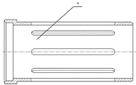
The structural scheme of mechanism that Fig. 2 is the pressure head sleeve assembly.
Fig. 3 is use state diagram one of the present invention.
Fig. 4 is use state diagram two of the present invention.
In upper figure, sequence number is: 1-depression bar, 2-bearing nut, 3-thrust ball bearing, 4-bearing plate, 5-gripper shoe, 6-contiguous block, 7-latch, 8-pressure head, 9-sleeve, 10-back-up ring, 11-the first screw, 12-support bar, 13-the first nut, 14-the second screw, 15-cylinder body, 16-thin-wall cylinder casing.
The specific embodiment
Describe the present invention below in conjunction with accompanying drawing in detail in the mode of embodiment.
Embodiment 1:
As shown in Figure 1, a kind of press mounting tool for thin-wall cylinder casing, press-fited for the thin-wall cylinder casing to an engine, comprises depression bar 1, gripper shoe component, three support bars 12 and pressure head sleeve assembly.
Depression bar 1 is the spindle with trapezoidal screw thread shape, and the intensity of trapezoidal thread is high, and centering is good, and processing performance is good, therefore select trapezoidal thread, optimal case when transmission, is to adopt Tr26 * 5 trapezoidal threads.The pressure head sleeve assembly is the tubular that an end seals an end opening, and the gripper shoe sub-assembly is set on depression bar 1, and an end of depression bar 1 is fixedly connected with an end of pressure head sleeve assembly sealing.
The gripper shoe sub-assembly comprises bearing plate 4, thrust ball bearing 3, bearing nut 2 and gripper shoe 5; Wherein, bearing plate 4 is provided with the lid shape part of through hole for axle center, and bearing plate 4 matches with the outer ring of thrust ball bearing 3, and the inner ring of thrust ball bearing 3 matches with bearing nut 2; In the present embodiment, thrust ball bearing 3 adopts 51108 bearings.The screw thread of the screw thread of bearing nut 2 and depression bar 1 is complementary.Thrust ball bearing 3 is set in bearing plate 4, and bearing plate 4 and thrust ball bearing 3 all are set on bearing nut 2, and the large end of bearing nut 2 is located thrust ball bearing 3, and contacts with gripper shoe 5.In the present embodiment, the small end of bearing nut 2 is turret head, is convenient to the operation of spanner.One end of gripper shoe 5 is fixedly connected with bearing plate 4 by the second screw 14, thereby makes bearing plate 4, thrust ball bearing 3, bearing nut 2 and the gripper shoe 5 fixing gripper shoe sub-assembly that forms successively; In the present embodiment, the second screw 14 adopts M10 * 50 hexagon socket cap head screws.The other end of gripper shoe 5 is fixedly connected with an end of support bar 12 by the first nut 13, and the two ends of support bar 12 are equipped with screw thread, and wherein the first nut 13 is the M12 nut.In the present embodiment, gripper shoe 5 is triangular in shape, on three angles of gripper shoe 5, is equipped with installing hole, utilizes the first nut 13 by installing hole, one end of support bar 12 to be fixed on gripper shoe 5.The other end of support bar 12 is for being connected with the cylinder head bolt hole of engine body.Realize relatively rotating by thrust ball bearing 3 between bearing nut 2 and gripper shoe 5, thereby reduced labour intensity, increase work efficiency.
The pressure head sleeve assembly comprises pressure head 8 and sleeve 9, and sleeve 9 is step-like cylinder, uniformly on the barrel of sleeve 9 offers six axial lightening grooves.The diameter of sleeve 9 front portions is greater than the diameter at rear portion, and is provided with a step surface between front and rear, and the diameter at sleeve 9 rear portions matches with the internal diameter of cylinder sleeve, and in the present embodiment, the diameter at sleeve 9 rear portions is 98mm.Pressure head 8 sealings are arranged on the end face of sleeve 9 front portions.The design of step surface guarantees between cylinder sleeve and pressure head sleeve assembly, can fit tightly when cylinder sleeve press-fits.In the present embodiment, as shown in Figure 2, at the step surface place, design a groove, make when cylinder sleeve press-fits the laminating between cylinder sleeve and pressure head sleeve assembly tightr.
In the present embodiment, depression bar 1 is connected with the pressure head sleeve assembly by a contiguous block 6; One end of contiguous block 6 is fixedly connected with pressure head 8 by the first screw 11, and the other end of contiguous block 6 is connected with an end of depression bar 1 by latch 7.In the present embodiment, the first screw 11 is M8 * 12 hexagon socket cap head screws.One end of depression bar 1 is chamfered edge optical axis with holes, and an end of contiguous block 6 is provided with latch groove and pin hole, and chamfered edge optical axis with holes inserts in the latch groove, and latch 7 is fixing by depression bar 1 by pin hole.Latch 7 is bearing pin, and an end of latch 7 is provided with circlip groove, by back-up ring 10, with circlip groove, coordinates, and depression bar 1 is fixedly connected with contiguous block 6, prevents the axial float of latch 7.In the present embodiment, back-up ring 10 is the d15 circlip for shaft.Realize the rotation of pressure head sleeve assembly after the cylinder jacket assembling by latch 7 between depression bar 1 and pressure head sleeve assembly, thereby reduce the longitudinal space demand.
Operation principle of the present invention and using method are as follows:
During work, referring to Fig. 3 and Fig. 4, in figure, heavy line is partly the present invention, and 16 is thin-wall cylinder casing, and 15 is cylinder body; Support bar 12 is filled to the place, cylinder head bolt hole on body cylinder cap faying face; Again depression bar 1, contiguous block 6, latch 7, pressure head 8, sleeve 9, back-up ring 10, the first screw 11 etc. are assembled into to a pressure head depression bar component; Bearing nut 2, thrust ball bearing 3, bearing plate 4, gripper shoe 5 and the second screw 14 etc. are assembled into to support group plate component; Then screwing of the bearing nut 2 of the depression bar by pressure head depression bar component 1 and gripper shoe sub-assembly, assemble pressure head depression bar component and gripper shoe sub-assembly; Clockwise rotating bearing nut 2 makes pressure head depression bar component in top dead center position; Rotate the pressure head sleeve assembly and make in level, cylinder jacket is filled on sleeve 9, hand rest makes the pressure head sleeve assembly straight down after living cylinder cap; Rotate counterclockwise bearing nut 2 step of sleeve 9 and cylinder jacket end face are fitted fully, be rotated further bearing nut 2 until cylinder jacket is press-fit into place fully; Clockwise rotate bearing nut 2, until the pressure head sleeve assembly breaks away from cylinder jacket fully; Unclamp the first nut 13, take off gripper shoe 5 etc.; Unclamp support bar 12 and take off.
The present invention fully takes into account the points for attention that thin wall cylinder cover press-fits, and can effectively guarantee the quality that press-fits of cylinder jacket.By the trial-production instrument is tested, the result demonstration has improved operating efficiency greatly, has alleviated labour intensity.
Above disclosed be only the application's specific embodiment, but the not limited thereto the changes that any person skilled in the art can think of of the application all should drop in the application's protection domain.