CN103476688A - Lifting device for a container - Google Patents
Lifting device for a container Download PDFInfo
- Publication number
- CN103476688A CN103476688A CN2012800173635A CN201280017363A CN103476688A CN 103476688 A CN103476688 A CN 103476688A CN 2012800173635 A CN2012800173635 A CN 2012800173635A CN 201280017363 A CN201280017363 A CN 201280017363A CN 103476688 A CN103476688 A CN 103476688A
- Authority
- CN
- China
- Prior art keywords
- lifting apparatus
- container
- draw bar
- support
- lifting device
- Prior art date
- Legal status (The legal status is an assumption and is not a legal conclusion. Google has not performed a legal analysis and makes no representation as to the accuracy of the status listed.)
- Granted
Links
Images


Classifications
-
- B—PERFORMING OPERATIONS; TRANSPORTING
- B65—CONVEYING; PACKING; STORING; HANDLING THIN OR FILAMENTARY MATERIAL
- B65D—CONTAINERS FOR STORAGE OR TRANSPORT OF ARTICLES OR MATERIALS, e.g. BAGS, BARRELS, BOTTLES, BOXES, CANS, CARTONS, CRATES, DRUMS, JARS, TANKS, HOPPERS, FORWARDING CONTAINERS; ACCESSORIES, CLOSURES, OR FITTINGS THEREFOR; PACKAGING ELEMENTS; PACKAGES
- B65D90/00—Component parts, details or accessories for large containers
- B65D90/12—Supports
- B65D90/18—Castors, rolls, or the like; e.g. detachable
-
- B—PERFORMING OPERATIONS; TRANSPORTING
- B65—CONVEYING; PACKING; STORING; HANDLING THIN OR FILAMENTARY MATERIAL
- B65D—CONTAINERS FOR STORAGE OR TRANSPORT OF ARTICLES OR MATERIALS, e.g. BAGS, BARRELS, BOTTLES, BOXES, CANS, CARTONS, CRATES, DRUMS, JARS, TANKS, HOPPERS, FORWARDING CONTAINERS; ACCESSORIES, CLOSURES, OR FITTINGS THEREFOR; PACKAGING ELEMENTS; PACKAGES
- B65D90/00—Component parts, details or accessories for large containers
- B65D90/0033—Lifting means forming part of the container
Landscapes
- Engineering & Computer Science (AREA)
- Mechanical Engineering (AREA)
- Forklifts And Lifting Vehicles (AREA)
- Handcart (AREA)
- Loading Or Unloading Of Vehicles (AREA)
- Warehouses Or Storage Devices (AREA)
- Carriers, Traveling Bodies, And Overhead Traveling Cranes (AREA)
- Magnetic Resonance Imaging Apparatus (AREA)
- Paper (AREA)
Abstract
Description
技术领域technical field
本发明涉及一种用于集装箱的抬升装置,更具体地说,本发明涉及一种附接有轮的抬升装置,其例如借助牵引机、叉车或某种其他车辆或施工场地机械被设置在施工场地内,用以抬起集装箱一端,从而能够部分地移动集装箱。The present invention relates to a lifting device for a container, and more particularly to a wheeled lifting device which is placed on a construction site, for example by means of a tractor, forklift or some other vehicle or construction site machinery. In the field, it is used to lift one end of the container, so that the container can be partially moved.
背景技术Background technique
众所周知,例如诸如吊钩式起重车(hook-lift truck)等重型运输设备设有必要的设备和充足的动力来抬起并移动沉重的集装箱。由于集装箱是被租借的,通常吊钩式起重车的司机会将集装箱放置在施工场地的一个给定位置,并将集装箱留在那里。当集装箱被装满或是与协议一致时会被取走。这种安排的缺点是当集装箱装满时会变得太重,以至于诸如牵引机、叉车和小型挖掘机等小型施工场地设备无法移动集装箱。因此集装箱的位置被限制于吊钩式起重车的司机把它放下的首个地点。通常,上述司机不熟悉施工场地,而且集装箱的位置也不便于要使用集装箱的人和在同一施工场地工作的其他人。一般来说,吊钩式起重车也如此之大,以至于被限制在宽广的地区和相对广阔的道路行驶。当集装箱被全部地或是部分地填充后,可能希望将其移走或是调整其在施工场地中的位置。为了移动或移走集装箱,现在不调用吊钩式起重车或是上述的类似设备是几乎不可能的,而且往往会导致不必要的长时间等待和额外的成本。It is well known that heavy transport equipment such as hook-lift trucks have the necessary equipment and sufficient power to lift and move heavy containers. Since the container is leased, usually the driver of the hook-lift truck will place the container at a given location on the construction site and leave the container there. Containers are picked up when they are full or as agreed. The downside of this arrangement is that when full the container becomes so heavy that small job site equipment such as tractors, forklifts and mini excavators cannot move the container. The position of the container is thus limited to the first place where the driver of the hook-lift truck lowers it. Usually, the above-mentioned drivers are not familiar with the construction site, and the location of the container is not convenient for the person who wants to use the container and other people working on the same construction site. Generally, hook lift trucks are also so large that they are restricted to wide areas and relatively wide roads. After the container is fully or partially filled, it may be desirable to remove it or reposition it on the construction site. In order to move or remove a container, it is now almost impossible without resorting to a hook-lift truck or similar equipment as mentioned above, and often results in unnecessarily long waits and additional costs.
发明内容Contents of the invention
本发明的目的在于弥补或减少现有技术的多个缺点中的至少一个,或至少提供一种对现有技术的有效替代方式。The purpose of the present invention is to remedy or reduce at least one of the disadvantages of the prior art, or at least provide an effective alternative to the prior art.
通过以下的说明和随后的权利要求中所指明的特征来实现这个目的。This object is achieved by the features specified in the following description and the following claims.
在本申请中,术语“集装箱”含义广泛,因此,这个术语包括所有类型的用于运输或临时存放固体和液体两种形式的货物的集装箱。例如,集装箱可以是、但不限于是不同类型的运输集装箱、钩吊式集装箱以及不同尺寸和形状的翻斗式箱体(dump body)。如果集装箱附接有如下所述的抬升装置,且在该集装箱的与附接该抬升装置的那一端相对的另一端设有一个或多个轮,这样是有优势的。结合根据本发明的抬升装置,就能够通过例如牵引机或施工场地机械等,在施工场地部分地移动沉重、满载的集装箱牵引机。In this application, the term "container" has a broad meaning, and therefore, this term includes all types of containers used for the transport or temporary storage of goods in both solid and liquid forms. For example, containers may be, but are not limited to, different types of shipping containers, hook-up containers, and dump bodies of different sizes and shapes. It is advantageous if the container is attached with a lifting device as described below and is provided with one or more wheels at the opposite end of the container to the end to which the lifting device is attached. In combination with a lifting device according to the invention, it is possible to partially move a heavy, fully loaded container tractor on a construction site, eg by a tractor or a construction site machine or the like.
更具体地,本发明涉及一种用于集装箱的抬升装置,该抬升装置被附接在集装箱的一端,并且抬升装置包括:起落架,设有一个或多个轮;以及驱动器,被设置成使该抬升装置的起落架在不接合支承面的第一位置与接合支承面的第二位置之间移动,以使得在该起落架处于接合支承面的位置时,集装箱的一端被抬离该支承面;抬升装置的特征在于,该抬升装置的起落架经由至少一个连接体连接到驱动器,该连接体连接驱动器并能够随驱动器移动。More specifically, the present invention relates to a lifting device for a container, the lifting device being attached at one end of the container and comprising: an undercarriage provided with one or more wheels; and a drive arranged to cause The undercarriage of the lifting device is movable between a first position not engaging the support surface and a second position engaging the support surface such that when the undercarriage is in the position engaging the support surface, one end of the container is lifted off the support surface The lifting device is characterized in that the undercarriage of the lifting device is connected to the driver via at least one connecting body, and the connecting body is connected to the driver and can move with the driver.
在一个实施例中,抬升装置可包括两个或更多个驱动器。In one embodiment, the lifting device may comprise two or more drives.
在一个优选实施例中,连接体可随驱动器线性地移动,但在一替代实施例中,驱动器可绕一转轴来旋转连接体,使得起落架被旋转到接合支承面的位置,此时集装箱的一端被抬离该支承面。In a preferred embodiment, the linkage moves linearly with the actuator, but in an alternative embodiment, the actuator rotates the linkage about an axis such that the undercarriage is rotated into a position to engage the support surface, at which point the container's One end is lifted off the support surface.
在另一个优选实施例中,作为一种替换或改进方式,驱动器和连接体被至少部分地置于一保护性的框架内。In another preferred embodiment, as an alternative or improvement, the driver and the connecting body are at least partially placed within a protective frame.
在一个实施例中,抬升装置可被附接至集装箱一端的表面。该抬升装置可被附接至集装箱的短边,但不以此为限。在一替代实施例中,抬升装置也可被附接至集装箱的底面或者集装箱的长边。对于不同的实施例,如果抬升装置被至少部分地置于或附接在集装箱中的凹槽内是有优势的。因此,集装箱可以被现有的标准化的集装箱起重机和运输设备抬起和运输,与没有上述抬升装置的集装箱相比却没有占据更多的空间。将抬升装置定位在凹槽内也能够使得多个带有抬升装置的集装箱叠置和填充得更紧密。In one embodiment, a lifting device may be attached to the surface at one end of the container. The lifting device may be attached to the short sides of the container, but is not limited thereto. In an alternative embodiment, the lifting device may also be attached to the bottom surface of the container or to the long sides of the container. For various embodiments it is advantageous if the lifting device is at least partially placed or attached in a recess in the container. Thus, the container can be lifted and transported by existing standardized container cranes and transport equipment without taking up more space than a container without the aforementioned lifting device. Locating the lifting device within the recess also enables more compact stacking and packing of multiple containers with the lifting device.
在一个优选实施例中,框架和/或连接体可利用非圆筒状的形状来形成。这可以防止连接体在使用过程中扭曲。例如,这个问题可通过矩形管式的连接体以及与连接体相适配的框架来解决。In a preferred embodiment, the frame and/or connector may be formed using a non-cylindrical shape. This prevents the connector from twisting during use. This problem can be solved, for example, by a rectangular tubular connection body and a frame adapted to the connection body.
在连接体的远离集装箱的一侧,该连接体还可连接到一支架,支架进一步连接到抬升装置的起落架。On the side of the connecting body remote from the container, the connecting body can also be connected to a bracket, which is further connected to the undercarriage of the lifting device.
在一个优选实施例中,至少在处于接合支承面的位置时,抬升装置的起落架可绕基本上垂直于支承面的转轴旋转。这将使通过在集装箱一端支撑集装箱且随起落架旋转的轮来移动集装箱更加容易,从而使集装箱能够在运输过程中转向。例如,集装箱可被车辆或施工场地机械牵拉,但也可能在一个替代实施例中,被车辆或施工场地机械推动。如果起落架能围绕基本垂直于支承面的转轴旋转至少180°是有优势的,这样使得集装箱可以拥有最小的转弯半径。In a preferred embodiment, the undercarriage of the lifting device is rotatable about an axis of rotation substantially perpendicular to the support surface, at least in the position engaging the support surface. This will make it easier to move the container by means of wheels that support the container at one end and rotate with the landing gear, allowing the container to turn during transport. For example, the container may be pulled by a vehicle or job site machine, but may also, in an alternative embodiment, be pushed by a vehicle or job site machine. It is advantageous if the undercarriage can be rotated by at least 180° about an axis of rotation substantially perpendicular to the support surface, so that the container can have a minimum turning radius.
在一个实施例中,抬升装置可包括牵引杆或类似装置。通过将牵引杆连接到车辆,可以有助于集装箱的移动。例如,车辆可以是牵引机、叉车或施工场地机械,但不以此为限。牵引杆被附接至抬升装置的可旋转的起落架是有优势的,这样使得集装箱的移动通过上述牵引杆的牵引将尽可能地灵活。In one embodiment, the lifting device may comprise a tow bar or similar device. Movement of the container can be facilitated by attaching a tow bar to the vehicle. For example, a vehicle may be, but is not limited to, a tractor, a forklift, or a construction site machine. It is advantageous that the drawbar is attached to the rotatable undercarriage of the lifting device, so that the movement of the container will be as flexible as possible by the traction of said drawbar.
在一个优选实施例中,牵引杆能够在至少抬起位置(raised position)与放下位置(lower position)之间被调节。这样的好处是,当牵引杆不被用来牵拉集装箱时,可随着被调整到抬起位置而至少部分地嵌入上述凹槽中。当牵引杆处于放下位置时,则能够如上所述被用于移动集装箱。In a preferred embodiment, the drawbar is adjustable between at least a raised position and a lower position. This has the advantage that when the drawbar is not being used to pull the container, it can be at least partially embedded in said groove as it is adjusted to the raised position. When the drawbar is in the lowered position it can then be used to move the container as described above.
在进一步优选的实施例中,牵引杆在其处于抬起位置时远离集装箱的一侧具有一钩接元件。这使得现有的标准化的起重和运输设备能够被允许使用,以吊钩式起重车为例,举例来说,用于将集装箱搬运到吊钩式起重车上,使集装箱从施工场地被运走。In a further preferred embodiment, the side of the drawbar facing away from the container in its raised position has a hooking element. This allows the use of existing standardized lifting and transport equipment, such as hook-lift trucks, for example, for handling containers onto the hook-lift trucks, allowing containers to be shipped away.
在进一步优化的实施例中,牵引杆上也可以形成有一孔,以使得当起落架在接合支承面的位置并且牵引杆在放下位置时,牵引杆也可以充当拖车的牵引杆。In a further preferred embodiment, the tow bar may also be formed with a hole so that when the undercarriage is in the position engaging the bearing surface and the tow bar is in the lowered position, the tow bar can also act as a tow bar for a trailer.
如果牵引杆被设置成在牵引杆处于抬起位置时,通过上部锁定机构被锁定在集装箱上,则是有优势的。这在牵引杆在其远离集装箱的一侧上设有上述钩接元件时特别合适。当集装箱借助吊钩式起重车或者类似设备被提升时,锁定装置可以将牵引杆锁定在集装箱上,以此减少驱动器的重量载荷。It is advantageous if the drawbar is arranged to be locked to the container by the upper locking mechanism when the drawbar is in the raised position. This is particularly suitable when the drawbar is provided with the aforementioned hooking elements on its side facing away from the container. When the container is lifted by means of a hook-lift truck or similar equipment, the locking device can lock the drawbar to the container, thereby reducing the weight load on the drive.
在一个优选实施例中,锁定装置包括被附接至集装箱的第一部分以及被附接至能由抬升装置移动的牵引杆的第二部分。通过将牵引杆调节到其抬起位置,并同时使起落架向上移动到其不接合支承面的位置,锁定装置的被附接至牵引杆的部分能够卡合锁定装置的被附接至集装箱的部分。例如,锁定装置可以包括位于牵引杆上的锁定杆(locking rod),当牵引杆被调整到其抬起位置并且抬升装置被移动到其不接合支承面的位置时,锁定杆卡合位于集装箱上的一组锁定爪。对比上面的描述,如果随着起落架被移动到其接合支承面的位置,牵引杆从锁定装置被自动地释放,则是有优势的,这样当集装箱被移动时牵引杆可以任意地被降低和使用。In a preferred embodiment, the locking device comprises a first part attached to the container and a second part attached to the drawbar movable by the lifting device. By adjusting the drawbar to its raised position and simultaneously moving the undercarriage up to its position where it does not engage the bearing surface, the portion of the locking device attached to the drawbar can engage the part of the locking device attached to the container. part. For example, the locking device may comprise a locking rod on the drawbar that snaps onto the container when the drawbar is adjusted to its raised position and the lifter is moved to its position where it does not engage the support surface A set of locking claws. In contrast to the description above, it is advantageous if the drawbar is automatically released from the locking device as the undercarriage is moved to its position engaging the support surface, so that the drawbar can be lowered and use.
在一优选实施例中,抬升装置还可以包括下部锁定机构,下部锁定机构被设置成在牵引杆的放下位置将牵引杆锁定到集装箱上。这样的好处是,当集装箱被牵拉时,能使抬升装置的驱动器载荷减轻。In a preferred embodiment, the lifting device may further comprise a lower locking mechanism arranged to lock the drawbar to the container in the lowered position of the drawbar. This has the advantage of lightening the drive of the lifting device when the container is being pulled.
在一个实施例中,移动抬升装置的起落架的驱动器可以是液压缸。例如,通过本领域技术人员已知的方式,液压缸能够被连接到牵引机或施工场地机械中的液压输出系统。在替代实施例中,驱动器可以是机械或气动式。例如,通过例如上述车辆和施工场地机械的输出电源的电力供给,驱动器能够例如被涡轮操控。In one embodiment, the drive for moving the undercarriage of the lifting device may be a hydraulic cylinder. For example, a hydraulic cylinder can be connected to a hydraulic output system in a tractor or job site machine by means known to those skilled in the art. In alternative embodiments, the drive may be mechanical or pneumatic. For example, the drive can be steered, for example by a turbine, via electrical power supply such as the output power supply of the vehicle and job site machinery mentioned above.
还描述了一种抬升集装箱的一端的方法,该方法利用被附接在集装箱的一端的抬升装置,抬升装置包括驱动器和具有一个或多个轮的起落架,其特征在于,该方法包括:利用驱动器使抬升装置的起落架从不接合支承面的第一位置移动到接合支承面的第二位置,从而使集装箱的一端被抬离支承面。Also described is a method of lifting one end of a container using a lifting device attached to one end of the container, the lifting device comprising a drive and an undercarriage having one or more wheels, characterized in that the method comprises: using The drive moves the undercarriage of the lifting device from a first position not engaging the support surface to a second position engaging the support surface such that one end of the container is lifted off the support surface.
对比上面的描述,在一个优选的实施例中,该方法进一步包括将集装箱附接至车辆,并借助该车辆来移动集装箱。In contrast to the above description, in a preferred embodiment the method further comprises attaching the container to a vehicle and moving the container by means of the vehicle.
附图说明Description of drawings
通过阅读参照以下附图对非限制性优选实施例所作的详细描述,本发明的其它特征、目的和优点将会变得更明显,附图中:Other characteristics, objects and advantages of the present invention will become more apparent by reading the detailed description of non-limiting preferred embodiments with reference to the following drawings, in which:
图1示出带有处于上部位置的抬升装置和处于抬起位置的牵引杆的集装箱的立体图;Figure 1 shows a perspective view of a container with a lifting device in an upper position and a drawbar in a raised position;
图2示出带有处于下部位置的抬升装置和处于抬起位置的牵引杆的集装箱的立体图;Figure 2 shows a perspective view of the container with the lifting device in the lowered position and the drawbar in the raised position;
图3示出带有处于下部位置的抬升装置和处于放下位置的牵引杆的集装箱的立体图;Figure 3 shows a perspective view of the container with the lifting device in the lowered position and the drawbar in the lowered position;
图4示出带有抬升装置和牵引杆的集装箱的分解图;Figure 4 shows an exploded view of the container with lifting device and drawbar;
图5示出带有处于上部位置的抬升装置和处于抬起位置的牵引杆的集装箱的侧视图;Figure 5 shows a side view of the container with the lifting device in the upper position and the drawbar in the raised position;
图6示出带有处于下部位置的抬升装置和处于放下位置的牵引杆的集装箱的侧视图;Figure 6 shows a side view of the container with the lifting device in the lowered position and the drawbar in the lowered position;
图7示出另一个实施例的一个带有处于上部位置的抬升装置和处于抬起位置的牵引杆的集装箱的立体图;Figure 7 shows a perspective view of another embodiment of a container with the lifting device in the upper position and the drawbar in the raised position;
图8示出图7中的带有处于下部位置的抬升装置和处于抬起位置的牵引杆的集装箱的立体图;Figure 8 shows a perspective view of the container of Figure 7 with the lifting device in the lowered position and the drawbar in the raised position;
图9示出图7中的带有处于下部位置的抬升装置和处于放下位置的牵引杆的集装箱的立体图;Figure 9 shows a perspective view of the container of Figure 7 with the lifting device in the lowered position and the drawbar in the lowered position;
图10示出图7中集装箱的局部分解图以及从另一种角度看到的该集装箱的放大的细节;Figure 10 shows a partially exploded view of the container in Figure 7 and an enlarged detail of the container seen from another angle;
图11示出图7的集装箱的端部表面的侧视图;以及Figure 11 shows a side view of the end surface of the container of Figure 7; and
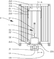
图12示出了通过图11中的剖面线A-A观察到的图7中集装箱的剖视图。Figure 12 shows a cross-sectional view of the container in Figure 7 as seen through section line A-A in Figure 11.
具体实施方式Detailed ways
在下文中,附图标记“1”表示根据本发明的一种抬升装置,而附图标记“2”表示被附接至抬升装置1的集装箱2。抬升装置1可以是集装箱2的集成部分,或者抬升装置1可以被改装到现有的集装箱2上。抬升装置1被附接在集装箱2的一端21。在附图中,抬升装置1被示出为附接至集装箱2的一个侧表面211上。更具体地,抬升装置1被示出为部分地位于处在侧表面211中的凹槽212内。因此,集装箱2在抬升装置1被附接至集装箱的情况下基本上不会比没有抬升装置1的集装箱2占用更多空间,因此,带有抬升装置1的集装箱2可以通过用于没有抬升装置的现有集装箱2(图中未示出)的相同方式和相同设备被摆放在运输车辆上。抬升装置1还设有一驱动器11,驱动器在附图中被示为液压缸11。例如,液压缸11可以通过本领域技术人员常用的方式连接到牵引机或施工场地机械的液压系统。在可替代的实施例中,驱动器11也可以是机械或气动式(图中未示出)。驱动器11被置于保护性的框架15内。驱动器11穿过驱动器框架15中的开口151,经由连接体12连接到支架14。连接体12被附接至驱动器11并随驱动器联动,举例来说,连接体12可以是矩形管或类似结构。支架14至少部分地被套环141包围,套环141上的一侧设有突出的凸耳143。在支架14的下侧,支架14进一步连接到抬升装置1的起落架13,起落架13可以绕位于支架14与起落架13之间的转轴133旋转。起落架13还设置有一个或多个轮131,例如图中所示的两个轮131。抬升装置1还设置有牵引杆3,如图所示,牵引杆3被附接至起落架13,并可随起落架旋转。牵引杆3通过本领域技术人员常用的方式被附接至起落架13。除了可以围绕转轴133转动之外,牵引杆3也可在抬起位置(参见图2和图5)与放下位置(参见图3和图6)之间被调整。在图1和图5中,抬升装置1被示出处在第一位置(上部位置),使得起落架13上的轮131几乎不与支承面接触。当抬升装置1处在第一位置(上部位置),侧表面211(连接抬升装置1被附接在该侧表面处)被支撑在一对分开的支撑腿213上,这对支撑腿位于集装箱的一端21。在图2、图3、图6中,驱动器11被示出处于第二位置(下部位置),其中起落架13上的轮131向下移动而与支承面接合,使得集装箱2的一端21被抬起。因此,集装箱2被部分地支撑在轮131上。集装箱2上的相对端23被一组分开的轮231支撑,这组轮231被附接在集装箱2的另一端(第二端)23处,因此,当抬升装置1处于第二位置而接触支承面时,集装箱2被支撑在位于集装箱的相对两端21、23的轮131、231上。集装箱2由此被设置成在轮上移动。牵引杆3还设有横杆32。当牵引杆3处于其抬起位置,并且抬升装置1处于第一位置(上部位置)时,横杆32能够卡合集装箱2上的一对上部锁定爪215。因此,当不使用时,牵引杆3可以被锁定在集装箱2上。当牵引杆3处在放下位置时,集装箱2被支撑在轮131、231上,牵引杆3例如可被附接至牵引机或施工场地机械(图中未示出),但不以此为限。例如,牵引杆3可以借助延伸穿过牵引杆3上的孔33的横杆32或开口销或类似部件(未示出),而被附接至车辆上。集装箱2因此可以很容易地通过牵引杆3和车辆(未示出)而被牵拉到新的位置。牵引杆3还设有钩接元件31;钩接元件31位于牵引杆的当牵引杆3处于抬起位置时远离集装箱2的那一侧。钩接元件31可例如被吊钩式起重车上的挂钩或是类似装置勾住,使得集装箱2能够被抬升到吊钩式起重车并以常用的方式运走(未示出)。当牵引杆3处于放下位置时,钩接元件31也能够对牵引杆3起到支撑作用。另外,集装箱2上还如图所示设有一组下部锁定爪217。当抬升装置1被移动到第二位置(下部位置)时,凸耳143与下部锁定爪217卡合,使得锁定爪和凸耳形成下部锁定装置。因此,当被牵拉时,集装箱2上的牵引杆3的载荷基本上分布在凸耳143与锁定爪217之间,使得支架14和驱动器11之间的连接体12载荷减轻。In the following, reference numeral "1" designates a lifting device according to the invention, while reference numeral "2" designates a
图7至图12示出根据本发明的抬升装置1的替代实施例。连接体12′通过连杆11上的连接器部112,被连接到驱动器11′的连杆111;连杆则借助图中未示出的螺栓或类似装置,被连接到连接体上的连接器部122。因此,连接体12′能够与驱动器11′一起移动。此外,连接体12′被固定地附接至保护性的框架15′的内部,使得框架15′也能够与驱动器11′一起移动。连接体12′可以通过现有技术例如通过焊接或借助一个或多个螺钉或螺栓,被附接至框架15′。框架15′上的一组轮152适用于而且被放置在位于集装箱的凹槽212中的两个U型剖面部214内,因此当连接体12′、且由此还有框架15′随驱动器11′移动时,轮152在U型剖面部214中滚动。U型剖面部214被示出为开口朝外,然而在一个未示出的实施例中,U型剖面部214的开口也可朝内,在图10的底部,框架15′被放大并以另一个视角示出,使得轮152能被看清。保护性的顶部216被置于抬升装置1上且处于集装箱的一端21,使得抬升装置1至少部分地在凹槽212内和顶部216下得到保护。此外,如分解图10及图11中最清楚地示出的,框架15′被示出为设有两个向下突出的锁定销153;锁定销153被设置成,当抬升装置1被移动到其第一位置从而接合支承面时,接合(插入)集装箱2上的一组锁定孔218,使得当集装箱2被牵拉的时候,驱动器11′的载荷减轻。锁定销153和锁定孔218由此形成下部锁定机构。7 to 12 show alternative embodiments of the
Claims (15)
Applications Claiming Priority (3)
| Application Number | Priority Date | Filing Date | Title |
|---|---|---|---|
| NO20110528A NO333058B1 (en) | 2011-04-06 | 2011-04-06 | Ceiling device for container |
| NO20110528 | 2011-04-06 | ||
| PCT/NO2012/050032 WO2012138229A1 (en) | 2011-04-06 | 2012-03-01 | Lifting device for a container |
Publications (2)
| Publication Number | Publication Date |
|---|---|
| CN103476688A true CN103476688A (en) | 2013-12-25 |
| CN103476688B CN103476688B (en) | 2015-07-22 |
Family
ID=46969411
Family Applications (1)
| Application Number | Title | Priority Date | Filing Date |
|---|---|---|---|
| CN201280017363.5A Expired - Fee Related CN103476688B (en) | 2011-04-06 | 2012-03-01 | Lifting device for a container |
Country Status (8)
| Country | Link |
|---|---|
| US (1) | US9266670B2 (en) |
| EP (1) | EP2694407B1 (en) |
| CN (1) | CN103476688B (en) |
| AU (1) | AU2012240662B2 (en) |
| CA (1) | CA2831831A1 (en) |
| DK (1) | DK2694407T3 (en) |
| NO (1) | NO333058B1 (en) |
| WO (1) | WO2012138229A1 (en) |
Cited By (3)
| Publication number | Priority date | Publication date | Assignee | Title |
|---|---|---|---|---|
| CN109795271A (en) * | 2019-01-25 | 2019-05-24 | 天津联汇智造科技有限公司 | A kind of dragging mechanism and mobile robot |
| CN109987356A (en) * | 2018-01-03 | 2019-07-09 | 集装箱轮转系统私人有限公司 | Container and cap assemblies and method for digging |
| CN118660853A (en) * | 2022-02-16 | 2024-09-17 | Wee挪威有限公司 | Devices, systems and methods for facilitating movement of objects |
Families Citing this family (5)
| Publication number | Priority date | Publication date | Assignee | Title |
|---|---|---|---|---|
| DE102012202461B4 (en) * | 2012-02-17 | 2014-07-10 | Siemens Aktiengesellschaft | Device for transporting and setting up a compressor |
| NO338223B1 (en) * | 2012-12-05 | 2016-08-08 | Jack Pack As | Lifting device for container and method using the same |
| US20150132092A1 (en) * | 2013-11-08 | 2015-05-14 | Jack Rust Burrell | Self-contained self-leveling moving and storage container and system |
| US10344487B2 (en) * | 2015-08-14 | 2019-07-09 | Oldcastle Light Building Products, LLC | Attachment and support members for modular building structures |
| US11167682B2 (en) * | 2017-01-11 | 2021-11-09 | Biosphere Aerospace, Llc | Modular container transport systems |
Citations (9)
| Publication number | Priority date | Publication date | Assignee | Title |
|---|---|---|---|---|
| US3570694A (en) * | 1968-11-26 | 1971-03-16 | Fruehauf Corp | Separable wheel units for vehiclizing container |
| US3788683A (en) * | 1972-07-10 | 1974-01-29 | J Rumell | Transport vehicle with portable cargo container |
| US3984013A (en) * | 1974-11-01 | 1976-10-05 | Herbert Wirz | Roll-on mechanism for loading a container onto a vehicle |
| DE3312585A1 (en) * | 1983-04-08 | 1984-10-18 | Busatis-Werke GmbH u. Co KG, 5630 Remscheid | Container transporting and storage system |
| FR2710041A1 (en) * | 1993-09-13 | 1995-03-24 | Beucher Guy | Device for facilitating the displacement of a container, particularly a skip |
| BE1009737A6 (en) * | 1995-11-09 | 1997-07-01 | Groep Stevens Int Nv | Transport device for a container |
| US5806863A (en) * | 1993-11-02 | 1998-09-15 | Cts Eurocontainer Und Transport-Vermittlungs Gmbh | Large-capacity transport container |
| CN2701841Y (en) * | 2004-04-14 | 2005-05-25 | 宋金辉 | Container handling and lifting device |
| CN201351060Y (en) * | 2009-01-23 | 2009-11-25 | 浙江理工大学 | Hydraulic lift-type tank transportation loading and unloading frame |
Family Cites Families (6)
| Publication number | Priority date | Publication date | Assignee | Title |
|---|---|---|---|---|
| US4452555A (en) * | 1981-09-18 | 1984-06-05 | The Union Corporation | Attachment apparatus |
| FR2597807B1 (en) * | 1986-04-24 | 1990-11-02 | Toutenkamion | HANDLING-ROLLING DEVICE AND ELEMENT FOR CONTAINERS OR THE LIKE |
| DE3830530A1 (en) * | 1988-09-08 | 1990-03-22 | Haacon Hebetech Gmbh | MOVABLE AND STEERABLE LIFTING OR DEPOSITING DEVICE FOR TRANSPORTABLE LARGE CONTAINERS |
| US5779255A (en) * | 1996-05-29 | 1998-07-14 | Garcia, Jr.; Daniel C. | Vessel transport carrier and method for transporting such vessel |
| CN2837246Y (en) * | 2005-09-09 | 2006-11-15 | 陈小军 | Multifunctional movable pulley |
| NO338223B1 (en) * | 2012-12-05 | 2016-08-08 | Jack Pack As | Lifting device for container and method using the same |
-
2011
- 2011-04-06 NO NO20110528A patent/NO333058B1/en not_active IP Right Cessation
-
2012
- 2012-03-01 WO PCT/NO2012/050032 patent/WO2012138229A1/en not_active Ceased
- 2012-03-01 US US14/007,929 patent/US9266670B2/en active Active
- 2012-03-01 CA CA2831831A patent/CA2831831A1/en not_active Abandoned
- 2012-03-01 AU AU2012240662A patent/AU2012240662B2/en not_active Ceased
- 2012-03-01 DK DK12768361.3T patent/DK2694407T3/en active
- 2012-03-01 EP EP12768361.3A patent/EP2694407B1/en not_active Not-in-force
- 2012-03-01 CN CN201280017363.5A patent/CN103476688B/en not_active Expired - Fee Related
Patent Citations (9)
| Publication number | Priority date | Publication date | Assignee | Title |
|---|---|---|---|---|
| US3570694A (en) * | 1968-11-26 | 1971-03-16 | Fruehauf Corp | Separable wheel units for vehiclizing container |
| US3788683A (en) * | 1972-07-10 | 1974-01-29 | J Rumell | Transport vehicle with portable cargo container |
| US3984013A (en) * | 1974-11-01 | 1976-10-05 | Herbert Wirz | Roll-on mechanism for loading a container onto a vehicle |
| DE3312585A1 (en) * | 1983-04-08 | 1984-10-18 | Busatis-Werke GmbH u. Co KG, 5630 Remscheid | Container transporting and storage system |
| FR2710041A1 (en) * | 1993-09-13 | 1995-03-24 | Beucher Guy | Device for facilitating the displacement of a container, particularly a skip |
| US5806863A (en) * | 1993-11-02 | 1998-09-15 | Cts Eurocontainer Und Transport-Vermittlungs Gmbh | Large-capacity transport container |
| BE1009737A6 (en) * | 1995-11-09 | 1997-07-01 | Groep Stevens Int Nv | Transport device for a container |
| CN2701841Y (en) * | 2004-04-14 | 2005-05-25 | 宋金辉 | Container handling and lifting device |
| CN201351060Y (en) * | 2009-01-23 | 2009-11-25 | 浙江理工大学 | Hydraulic lift-type tank transportation loading and unloading frame |
Cited By (4)
| Publication number | Priority date | Publication date | Assignee | Title |
|---|---|---|---|---|
| CN109987356A (en) * | 2018-01-03 | 2019-07-09 | 集装箱轮转系统私人有限公司 | Container and cap assemblies and method for digging |
| CN109795271A (en) * | 2019-01-25 | 2019-05-24 | 天津联汇智造科技有限公司 | A kind of dragging mechanism and mobile robot |
| CN109795271B (en) * | 2019-01-25 | 2023-09-12 | 天津联汇智造科技有限公司 | A drag mechanism and mobile robot |
| CN118660853A (en) * | 2022-02-16 | 2024-09-17 | Wee挪威有限公司 | Devices, systems and methods for facilitating movement of objects |
Also Published As
| Publication number | Publication date |
|---|---|
| NO333058B1 (en) | 2013-02-25 |
| US9266670B2 (en) | 2016-02-23 |
| NO20110528A1 (en) | 2012-10-08 |
| WO2012138229A1 (en) | 2012-10-11 |
| AU2012240662B2 (en) | 2016-03-03 |
| CA2831831A1 (en) | 2012-10-11 |
| DK2694407T3 (en) | 2016-05-17 |
| EP2694407B1 (en) | 2016-02-10 |
| AU2012240662A1 (en) | 2013-10-31 |
| CN103476688B (en) | 2015-07-22 |
| EP2694407A4 (en) | 2014-09-17 |
| EP2694407A1 (en) | 2014-02-12 |
| US20140054303A1 (en) | 2014-02-27 |
Similar Documents
| Publication | Publication Date | Title |
|---|---|---|
| CN103476688B (en) | Lifting device for a container | |
| EP1871641B1 (en) | Apparatus for lifting, handling and transporting a container | |
| EP1259398B1 (en) | An apparatus for lifting, handling and transporting a container | |
| US8646753B2 (en) | System for transporting shipping containers | |
| US6071062A (en) | Apparatus for lifting, handling, and transporting a container | |
| US8910957B1 (en) | Self-loading mini dolly | |
| CN102282042B (en) | container trailer | |
| CN104684756B (en) | The tipping wagon linked up with including slide hinged formula | |
| CN103118969B (en) | Vehicle support means | |
| CN104066619B (en) | Container handling device and related method | |
| US8733479B2 (en) | Remote controlled load transport system | |
| CN104837746B (en) | Lifting device and using method thereof for container | |
| US8186704B2 (en) | Gooseneck trailer attachment assembly and center deck elevation system | |
| CN101180193A (en) | Equipment for lifting, handling and transporting containers | |
| US20060045691A1 (en) | Retractable transportation system | |
| CN118660853A (en) | Devices, systems and methods for facilitating movement of objects | |
| KR20230000325U (en) | The dump trailer for agriculture | |
| EP0691911A1 (en) | Removable chassis for loading, unloading and transferring containers | |
| HK1050880B (en) | An apparatus for lifting, handling and transporting a container |
Legal Events
| Date | Code | Title | Description |
|---|---|---|---|
| C06 | Publication | ||
| PB01 | Publication | ||
| C10 | Entry into substantive examination | ||
| SE01 | Entry into force of request for substantive examination | ||
| C14 | Grant of patent or utility model | ||
| GR01 | Patent grant | ||
| CF01 | Termination of patent right due to non-payment of annual fee |
Granted publication date: 20150722 Termination date: 20170301 |
|
| CF01 | Termination of patent right due to non-payment of annual fee |