CN103465645A - Inkjet printer and cloth releasing mechanism - Google Patents
Inkjet printer and cloth releasing mechanism Download PDFInfo
- Publication number
- CN103465645A CN103465645A CN2013104268700A CN201310426870A CN103465645A CN 103465645 A CN103465645 A CN 103465645A CN 2013104268700 A CN2013104268700 A CN 2013104268700A CN 201310426870 A CN201310426870 A CN 201310426870A CN 103465645 A CN103465645 A CN 103465645A
- Authority
- CN
- China
- Prior art keywords
- supply roller
- cloth
- cloth supply
- travelling gear
- print media
- Prior art date
- Legal status (The legal status is an assumption and is not a legal conclusion. Google has not performed a legal analysis and makes no representation as to the accuracy of the status listed.)
- Granted
Links
- 239000004744 fabric Substances 0.000 title claims abstract description 183
- 230000007246 mechanism Effects 0.000 title claims abstract description 49
- 239000007921 spray Substances 0.000 claims description 21
- 230000001680 brushing effect Effects 0.000 claims description 16
- 230000008676 import Effects 0.000 claims description 6
- 230000008901 benefit Effects 0.000 abstract description 9
- 238000007639 printing Methods 0.000 abstract description 8
- 230000005540 biological transmission Effects 0.000 abstract description 4
- 238000000034 method Methods 0.000 description 11
- 230000008569 process Effects 0.000 description 11
- 238000010586 diagram Methods 0.000 description 5
- 238000005096 rolling process Methods 0.000 description 5
- 238000009434 installation Methods 0.000 description 4
- 230000000694 effects Effects 0.000 description 2
- 238000005516 engineering process Methods 0.000 description 2
- 230000009286 beneficial effect Effects 0.000 description 1
- 230000008859 change Effects 0.000 description 1
- 210000004276 hyalin Anatomy 0.000 description 1
- 230000006872 improvement Effects 0.000 description 1
- 238000007641 inkjet printing Methods 0.000 description 1
- 239000012528 membrane Substances 0.000 description 1
- 230000004048 modification Effects 0.000 description 1
- 238000012986 modification Methods 0.000 description 1
- 125000006850 spacer group Chemical group 0.000 description 1
Images


Landscapes
- Treatment Of Fiber Materials (AREA)
- Advancing Webs (AREA)
Abstract
The invention relates to an inkjet printer and a cloth releasing mechanism. The cloth releasing mechanism is used for bearing coiled printing media and evenly and flatly conveying the printing media to a platform. The cloth releasing mechanism comprises a first cloth releasing roller and a second cloth releasing roller which are arranged in parallel at intervals. The rotation speed of the first cloth releasing roller is larger than that of the second cloth releasing roller. The coiled printing media are placed on the first cloth releasing roller and the second cloth releasing roller. A driving gear drives the first cloth releasing roller and the second cloth releasing roller to rotate, so that the movable ends of the printing media are smoothly led out. After cloth releasing mechanism is applied to the inkjet printer, the loosing and twisting problems of the printing media in the transmission process can be effectively solved, conveying quality of the printing media is effectively improved, and the cloth releasing mechanism has the advantages of being simple in structure, convenient to use, reliable, and the like.
Description
Technical field
The present invention relates to the color spray drawing machine field, particularly a kind of large-scale spray drawing machine and put cloth mechanism.
Background technology
Spray drawing machine refers to a kind of product of large colour spray drawing machine series, it is mainly the inkjet printing for large-breadth printing media such as advertising poster, outdoor wall advertisements, and this print media comprises lamp house cloth, lamp sheet, body sticker, PP, single subsides, hyaline membrane etc. thoroughly.The most fabric width of spray drawing machine in the market is all over more than 3 meters, the width of its corresponding web-like print media and weight also increase thereupon, therefore in the process of printing, the package print media need import print media into the air brushing platform by the large-scale cloth mechanism of putting, the commonly used cloth mechanism of putting all is provided with cloth supply roller at present, work feed wheel and cloth-gathering roller, due to frictional force mechanism not being set, make print media easily cause print media distortion in the process of importing the air brushing platform into and the cloth effect is put in impact, thereby the transmission efficiency and the print quality that directly cause print media, even may the miscellaneous part of spray drawing machine be caused damage.
Summary of the invention
The object of the present invention is to provide and a kind ofly can in sending the print media process, effectively prevent that print media is loosening, the putting cloth mechanism and comprise the spray drawing machine that this puts cloth mechanism of distortion.
The present invention solves the problems of the technologies described above adopted technical scheme: a kind of cloth mechanism of putting, it is for carrying the web-like print media and making the movable end of print media evenly entirely import the air brushing platform into, this is put cloth mechanism and comprises the first cloth supply roller and the second cloth supply roller that is the parallel interval setting, rotating in same direction is so that be placed on described the first cloth supply roller and the web-like print media of the second cloth supply roller top is released with certain speed at work for described the first cloth supply roller and the second cloth supply roller, and the rotating speed of described the first cloth supply roller is greater than the rotating speed of described the second cloth supply roller.
In a preferred embodiment, described the first cloth supply roller is identical with the second cloth supply roller diameter, the one end coaxially is fixed with respectively the first travelling gear and the second travelling gear, the first travelling gear is connected by motor-driven driving gear by one with the second travelling gear, and the diameter of described the first travelling gear is less than the diameter of described the second travelling gear.
In a preferred embodiment, described the first cloth supply roller is identical with the second cloth supply roller diameter, one end of described the first cloth supply roller coaxially is fixed with the first travelling gear, the first travelling gear and one is by motor-driven driving gear engagement, be equipped with for limiting the damper of its rotating speed described the first travelling gear and described driving gear engagement assembling on described the second cloth supply roller.
In a preferred embodiment, the diameter of described the first cloth supply roller is greater than the diameter of described the second cloth supply roller, the one end coaxially is fixed with respectively the first travelling gear and the second travelling gear that specification is identical, and described the first travelling gear is connected by motor-driven driving gear by one with the second travelling gear.
In a preferred embodiment, this is put cloth mechanism and comprises and be the first cloth supply roller and the second cloth supply roller that parallel interval arranges, and described the first cloth supply roller and the second cloth supply roller rotating speed of independent rotation and the first cloth supply roller respectively are greater than the rotating speed of described the second cloth supply roller.
A kind of spray drawing machine, it comprises the as above described cloth mechanism of putting of any one.
Spray drawing machine of the present invention and the beneficial effect of putting cloth mechanism are: utilize and put the web-like print media that cloth mechanism will carry above it and evenly entirely import the air brushing platform into, this is put cloth mechanism and comprises the first cloth supply roller and the second cloth supply roller that is the parallel interval setting, and the rotating speed of the first cloth supply roller is greater than the rotating speed of described the second cloth supply roller, the web-like print media is placed on the top of the first cloth supply roller and the second cloth supply roller, and drive the first cloth supply roller and the rotation of the second cloth supply roller by driving gear, thereby the movable end of print media is drawn smoothly.After spray drawing machine of the present invention adopts this to put cloth mechanism, can effectively solve print media and produce problem loosening, distortion in transmission process, effectively raise the delivery quality of print media, this is put cloth mechanism and has the advantages such as simple in structure, easy to use, reliable.
The accompanying drawing explanation
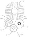
Fig. 1 is put cloth mechanism and web-like print media installation site schematic diagram in the first embodiment.
Fig. 2 is put cloth mechanism and web-like print media installation site schematic diagram in the second embodiment.
Fig. 3 is put cloth mechanism and web-like print media installation site schematic diagram in the 3rd embodiment.
Fig. 4 is put cloth mechanism and web-like print media installation site schematic diagram in the 4th embodiment.
Fig. 5 comprises arbitrary structural representation and the print media of putting the spray drawing machine of cloth mechanism of Fig. 1 to Fig. 4 to move towards schematic diagram in one embodiment.
The specific embodiment
Below in conjunction with specific embodiment and accompanying drawing to spray drawing machine of the present invention with put cloth mechanism and be described in further detail.
The spray drawing machine of putting cloth mechanism and using it of the present invention, be existing spray drawing machine to be put to the improvement of cloth mechanism, and being mainly increases the friction in input process to print media to regulate so that print media can be smooth orderly pass through the air brushing platform.
A kind of cloth mechanism of putting, it can evenly entirely import the air brushing platform into after carrying the web-like print media and making its movable end break away from coil structure.
Refer to Fig. 1, a kind of cloth mechanism of putting, it comprises the first cloth supply roller 20 and the second cloth supply roller 30 that is the parallel interval setting, web-like print media 10 is separable is placed on the top of the first cloth supply roller 20 and the second cloth supply roller 30 closely tangent with it, so that the movable end 11 of print media 10 produces rolling friction respectively and between the first cloth supply roller 20 and the second cloth supply roller 30, the tangent place of package print media 10 and the first cloth supply roller 20 and the second cloth supply roller 30 produces respectively the first frictional force F1 and the second frictional force F2, at work, the first cloth supply roller 20 and the second cloth supply roller 30 rotating in same directions are released with certain speed after the disengaging coil structure so that the movable end 11 of web-like print media 10 is taken advantage of a situation, and draw from the spacer region of the first cloth supply roller 20 and the second cloth supply roller 30.
The rotating speed that the first cloth supply roller 20 and the second cloth supply roller 30 are uniform rotation in the same way and the first cloth supply roller 20 is greater than the second cloth supply roller 30, therefore, the first frictional force F1 is greater than the second frictional force F2, so web-like print media 10 is in being pulled the process of rotation, its outer print media can tightly paste on its package structure and unlikely generation breaks away from, and then the movable end 11 of package print media 10 can evenly entirely be drawn.
Preferably, for guaranteeing print media, can not produce loosening, distortion, crumpled problem in the process transmitted, the speed discrepancy of the first cloth supply roller 20 and the second cloth supply roller 30 can obtain an optimum value by the test of limited number of time respectively according to different print media.For the rotating speed that meets the first cloth supply roller 20 is greater than the rotating speed of the second cloth supply roller 30, can be coordinated by following multiple frame for movement.
Refer to Fig. 1, in the first embodiment, the first cloth supply roller 20 is identical with the diameter of the second cloth supply roller 30, coaxially be fixed with respectively the first travelling gear 21 and the second travelling gear 31 at the one end, and, the first travelling gear 21 is connected by motor-driven driving gear 40 by one with the second travelling gear 31, this first travelling gear 21 and the second travelling gear 31 can assemble with driving gear 40 engagements respectively, in putting the process of cloth, by motor, can make driving gear 40 rotate, and then drive the rotation of taking advantage of a situation of the first travelling gear 21 and the second travelling gear 31 simultaneously, preferably, the diameter of the first travelling gear 21 is less than the diameter of the second travelling gear 31, thereby the rotating speed that can make the first cloth supply roller 20 is greater than the rotating speed of the second cloth supply roller 30, under the pressure of package print media, and then make the first frictional force F1 between the first cloth supply roller 20 and print media be greater than the second frictional force F2 between the second cloth supply roller 30 and print media.
Refer to Fig. 2, in a second embodiment, the first cloth supply roller 20 ' is identical with the diameter of the second cloth supply roller 30 ', one end of the first cloth supply roller 20 ' coaxially is fixed with the first travelling gear 21 ', the first travelling gear 21 ' is connected by motor-driven driving gear 40 ' with one, on the second cloth supply roller 30 ', be equipped with for limiting the damper 33 ' of its rotating speed, the first travelling gear 21 ' and driving gear 40 ' engagement assembling, in putting the cloth process, by motor, can make driving gear 40 ' rotate, and then drive the rotation of taking advantage of a situation of the first travelling gear 21 ' simultaneously, under the force of rolling friction effect, package print media 10 rotation of also taking advantage of a situation, and then second cloth supply roller 30 ' also along with the rotation of package print media 10, rotate, because of on the second cloth supply roller 30 ', be equipped with for limiting the damper 32 ' of its rotating speed, the rotating speed that can control the second cloth supply roller 30 ' by this damper 32 ' is less than the rotating speed of package print media 10, can make the rotating speed of the second cloth supply roller 30 ' be less than the rotating speed of the first cloth supply roller 20 ', under the pressure of package print media, and then make the first frictional force F1 ' between the first cloth supply roller 20 ' and print media be greater than the second frictional force F2 ' between the second cloth supply roller 30 ' and print media.
Refer to Fig. 3, in the 3rd embodiment, the diameter of the first cloth supply roller 20 ' ' diameter be greater than the second cloth supply roller 30 ' ', coaxially be fixed with respectively the first travelling gear 21 ' of same size at the one end ' and the second travelling gear 31 ' ', this first travelling gear 21 ' ' with the second travelling gear 31 ' ' by one by motor-driven driving gear 40 ' ' be connected, in putting the cloth process, can make driving gear 40 ' by motor ' rotate, and then drive the first travelling gear 21 ' ' and the second travelling gear 31 ' ' rotation of taking advantage of a situation, the diameter of ' diameter be greater than the second cloth supply roller 30 ' ' because of the first cloth supply roller 20 ', the rotating speed of so the first cloth supply roller 20 ' ' rotating speed be greater than the second cloth supply roller 30 ' ', under the pressure of package print media, and then make the first cloth supply roller 20 ' ' and print media between the first frictional force F1 ' ' be greater than the second cloth supply roller 30 ' ' and print media between the second frictional force F2 ' '.
Refer to Fig. 4, in the 4th embodiment, this is put cloth mechanism and comprises two the first cloth supply rollers 20 ' that specification is identical ' ' and the second cloth supply roller 30 ' ' ', also can be respectively fitted with the first travelling gear 21 ' that specification is identical on it ' ' and the second travelling gear 31 ' ' ', in putting the process of cloth, can control respectively the first cloth supply roller 20 ' by other external force ' ' and the second cloth supply roller 30 ' ' ' rotating speed, perhaps control respectively the first travelling gear 21 ' ' ' and the second travelling gear 31 ' ' ' rotating speed and then control the first cloth supply roller 20 ' ' ' and the second cloth supply roller 30 ' ' ' rotation of taking advantage of a situation, and make the first cloth supply roller 20 ' ' ' rotating speed be greater than the second cloth supply roller 30 ' ' ' rotating speed, under the pressure of package print media, and then make the first cloth supply roller 20 ' ' ' and print media between the first frictional force F1 ' ' ' be greater than the second cloth supply roller 30 ' ' ' and print media between the second frictional force F2 ' ' '.
Understandable, in other embodiments, also can control respectively by other external force factors or mechanical combination the rotating speed of the first backing roll and the second backing roll, and make the rotating speed of the rotating speed of the first backing roll higher than the second backing roll, thereby make the first frictional force F1 between the first cloth supply roller and print media be greater than the second frictional force F2 between the second cloth supply roller 30 and print media.
Please be simultaneously referring to Fig. 5, a kind of spray drawing machine, at least comprise integral-rack and be arranged on the air brushing platform 60 of frame top, it also comprises puts cloth mechanism and cloth-gathering roller 50 described in above-mentioned arbitrary embodiment, and, for the folding and unfolding that makes print media degree of being added with more, this spray drawing machine also comprises that one has completed the cloth-gathering roller 50 of the print media movable end 11 of air brushing operation for rolling; The web-like print media can make its movable end 11 at the uniform velocity break away from coil structure to import air brushing platform 60 into by putting cloth mechanism again, and after air brushing completes, print media movable end 11 is coil structure by cloth-gathering roller 50 rollings again.
The workflow of spray drawing machine of the present invention is: after start, put cloth mechanism when driving print media movable end 11 and move and make its air brushing face to pass through air brushing platform along the direction of arrow all the time towards top, in this process, the rotating speed of the first cloth supply roller 20 is greater than the rotating speed of the second cloth supply roller 30 all the time, and remain fixing speed discrepancy, therefore print media all the time can be in balanced frictional force state, can not cause the print media distortion fully, print media movable end 11 is after the air brushing platform jet-drawing completes, fall downwards and be sent to cloth-gathering roller, again by cloth-gathering roller by air brushing completes print media movable end 11 rollings.
To sum up, spray drawing machine of the present invention and put cloth mechanism, utilization is put the web-like print media that cloth mechanism will carry above it and is evenly entirely imported the air brushing platform into, this is put cloth mechanism and comprises the first cloth supply roller and the second cloth supply roller that is the parallel interval setting, and the rotating speed of the first cloth supply roller is greater than the rotating speed of described the second cloth supply roller, the web-like print media is placed on the top of the first cloth supply roller and the second cloth supply roller, and drive the first cloth supply roller and the rotation of the second cloth supply roller by driving gear, thereby the movable end of print media is drawn smoothly.After spray drawing machine of the present invention adopts this to put cloth mechanism, can effectively solve print media and produce loosening, distortion, crumpled problem in transmission process, effectively raise the delivery quality of print media, this is put cloth mechanism and has simple in structure, the advantages such as debugging is simple, easy to use, reliable.
Although the description of this invention carries out in conjunction with above specific embodiment,, those skilled in the art that can carry out many replacements, modifications and variations, be apparent according to above-mentioned content.Therefore, all such substituting, improve and change all are included in the spirit and scope of attached claim.
Claims (6)
1. put cloth mechanism for one kind, it is for carrying the web-like print media and making the movable end of print media evenly entirely import the air brushing platform into, it is characterized in that, this is put cloth mechanism and comprises the first cloth supply roller and the second cloth supply roller that is the parallel interval setting, rotating in same direction is so that be placed on described the first cloth supply roller and the web-like print media of the second cloth supply roller top is released with certain speed at work for described the first cloth supply roller and the second cloth supply roller, and the rotating speed of described the first cloth supply roller is greater than the rotating speed of described the second cloth supply roller.
2. the cloth mechanism of putting according to claim 1, it is characterized in that, described the first cloth supply roller is identical with the second cloth supply roller diameter, the one end coaxially is fixed with respectively the first travelling gear and the second travelling gear, the first travelling gear is connected by motor-driven driving gear by one with the second travelling gear, and the diameter of described the first travelling gear is less than the diameter of described the second travelling gear.
3. the cloth mechanism of putting according to claim 1, it is characterized in that, described the first cloth supply roller is identical with the second cloth supply roller diameter, one end of described the first cloth supply roller coaxially is fixed with the first travelling gear, the first travelling gear and one is by motor-driven driving gear engagement, be equipped with for limiting the damper of its rotating speed described the first travelling gear and described driving gear engagement assembling on described the second cloth supply roller.
4. the cloth mechanism of putting according to claim 1, it is characterized in that, the diameter of described the first cloth supply roller is greater than the diameter of described the second cloth supply roller, the one end coaxially is fixed with respectively the first travelling gear and the second travelling gear that specification is identical, and described the first travelling gear is connected by motor-driven driving gear by one with the second travelling gear.
5. the cloth mechanism of putting according to claim 1, it is characterized in that, this is put cloth mechanism and comprises and be the first cloth supply roller and the second cloth supply roller that parallel interval arranges, and described the first cloth supply roller and the second cloth supply roller rotating speed of independent rotation and the first cloth supply roller respectively are greater than the rotating speed of described the second cloth supply roller.
6. a spray drawing machine, is characterized in that, it comprises the cloth mechanism of putting as described as above-mentioned claim 1-5 any one.
Priority Applications (1)
| Application Number | Priority Date | Filing Date | Title |
|---|---|---|---|
| CN201310426870.0A CN103465645B (en) | 2013-09-18 | 2013-09-18 | A kind of spray drawing machine and Fang Bu mechanism |
Applications Claiming Priority (1)
| Application Number | Priority Date | Filing Date | Title |
|---|---|---|---|
| CN201310426870.0A CN103465645B (en) | 2013-09-18 | 2013-09-18 | A kind of spray drawing machine and Fang Bu mechanism |
Publications (2)
| Publication Number | Publication Date |
|---|---|
| CN103465645A true CN103465645A (en) | 2013-12-25 |
| CN103465645B CN103465645B (en) | 2016-02-03 |
Family
ID=49790789
Family Applications (1)
| Application Number | Title | Priority Date | Filing Date |
|---|---|---|---|
| CN201310426870.0A Active CN103465645B (en) | 2013-09-18 | 2013-09-18 | A kind of spray drawing machine and Fang Bu mechanism |
Country Status (1)
| Country | Link |
|---|---|
| CN (1) | CN103465645B (en) |
Cited By (3)
| Publication number | Priority date | Publication date | Assignee | Title |
|---|---|---|---|---|
| CN109466958A (en) * | 2018-08-23 | 2019-03-15 | 深圳市汉拓数码有限公司 | Conveying device and printing medium winding method |
| US10625523B2 (en) | 2016-05-27 | 2020-04-21 | Hewlett-Packard Development Company, L.P. | Braking system |
| CN113443471A (en) * | 2020-03-27 | 2021-09-28 | 兄弟工业株式会社 | Media cassette |
Citations (5)
| Publication number | Priority date | Publication date | Assignee | Title |
|---|---|---|---|---|
| CN2097729U (en) * | 1990-06-21 | 1992-03-04 | 山东省费县机械厂 | Synchronizing dish paper cutting machine |
| CN200967695Y (en) * | 2006-11-21 | 2007-10-31 | 黄豪宇 | Pneumatic constant tensile-force roll-release automatic control device |
| US20090152795A1 (en) * | 2007-12-18 | 2009-06-18 | International Business Machines Corporation | Compact low paper sensor mechanism |
| CN101929033A (en) * | 2010-09-09 | 2010-12-29 | 常州市第八纺织机械有限公司 | Unwinding device for warp knitting machine |
| CN203460556U (en) * | 2013-09-18 | 2014-03-05 | 惠州市惠阳环球数码科技设备有限公司 | Inkjet printer and cloth feeding mechanism |
-
2013
- 2013-09-18 CN CN201310426870.0A patent/CN103465645B/en active Active
Patent Citations (5)
| Publication number | Priority date | Publication date | Assignee | Title |
|---|---|---|---|---|
| CN2097729U (en) * | 1990-06-21 | 1992-03-04 | 山东省费县机械厂 | Synchronizing dish paper cutting machine |
| CN200967695Y (en) * | 2006-11-21 | 2007-10-31 | 黄豪宇 | Pneumatic constant tensile-force roll-release automatic control device |
| US20090152795A1 (en) * | 2007-12-18 | 2009-06-18 | International Business Machines Corporation | Compact low paper sensor mechanism |
| CN101929033A (en) * | 2010-09-09 | 2010-12-29 | 常州市第八纺织机械有限公司 | Unwinding device for warp knitting machine |
| CN203460556U (en) * | 2013-09-18 | 2014-03-05 | 惠州市惠阳环球数码科技设备有限公司 | Inkjet printer and cloth feeding mechanism |
Cited By (3)
| Publication number | Priority date | Publication date | Assignee | Title |
|---|---|---|---|---|
| US10625523B2 (en) | 2016-05-27 | 2020-04-21 | Hewlett-Packard Development Company, L.P. | Braking system |
| CN109466958A (en) * | 2018-08-23 | 2019-03-15 | 深圳市汉拓数码有限公司 | Conveying device and printing medium winding method |
| CN113443471A (en) * | 2020-03-27 | 2021-09-28 | 兄弟工业株式会社 | Media cassette |
Also Published As
| Publication number | Publication date |
|---|---|
| CN103465645B (en) | 2016-02-03 |
Similar Documents
| Publication | Publication Date | Title |
|---|---|---|
| CN105947727A (en) | A damping unwinding mechanism for inkjet cloth | |
| CN202754590U (en) | Auxiliary winding device | |
| CN103465645A (en) | Inkjet printer and cloth releasing mechanism | |
| CN203460556U (en) | Inkjet printer and cloth feeding mechanism | |
| CN207536848U (en) | A kind of portable colour band turns volume machine | |
| CN102115946B (en) | An anti-reverse rolling cloth device for flat knitting machines | |
| CN104355189A (en) | Flexible external cloth winding mechanism | |
| CN203038614U (en) | Rolling type advertisement player | |
| CN204280918U (en) | The outer cloth-winding mechanism of a kind of flexible machine | |
| CN202213278U (en) | Fixed-length stretching multifunctional compound machine | |
| CN203439804U (en) | Coiled material code-spraying conveying device | |
| CN201971492U (en) | Friction-free and damage-free drawing device | |
| CN203959430U (en) | The coreless rolls rewinding machine that paper roll core elasticity is adjustable | |
| CN201099054Y (en) | Winding drum film automatic code printing machine | |
| CN201395429Y (en) | Slitting machine side pressure coiling device | |
| CN211594447U (en) | Automatic change permanent tension mica paper coiling mechanism | |
| CN203143771U (en) | Strip receiving and rolling machine structure | |
| CN205156556U (en) | Stable jelly transfer mechanism for jelly drying device | |
| CN202011659U (en) | Straining device of coiling machine | |
| CN201882668U (en) | Novel friction rolling machine | |
| CN202298182U (en) | Cloth tightener | |
| CN203903570U (en) | Constant-speed rolling machine | |
| CN208998481U (en) | A kind of mica tape double-station unwinding drying unit | |
| CN105931577A (en) | A spray-painted cloth advertising display mechanism | |
| CN206351977U (en) | A kind of cloth coiler device |
Legal Events
| Date | Code | Title | Description |
|---|---|---|---|
| C06 | Publication | ||
| PB01 | Publication | ||
| C10 | Entry into substantive examination | ||
| SE01 | Entry into force of request for substantive examination | ||
| C14 | Grant of patent or utility model | ||
| GR01 | Patent grant | ||
| C41 | Transfer of patent application or patent right or utility model | ||
| TR01 | Transfer of patent right |
Effective date of registration: 20170216 Address after: 516211 Guangdong, Huiyang Economic Development Zone, Hui Yi Road (East), the sub section of the plant A Patentee after: Huizhou Huanqiu Feiteng Digital Equipment Co Ltd Address before: 516213 Huiyang City, Guangdong Province, the economic development zone, and the light of the road on the eastern side of the building on the eastern side of the road on the eastern side of the road, three, Patentee before: Universal Digital Technology Equipment Ltd. |