CN103440643A - Single-linear-array camera calibration method - Google Patents
Single-linear-array camera calibration method Download PDFInfo
- Publication number
- CN103440643A CN103440643A CN2013103412649A CN201310341264A CN103440643A CN 103440643 A CN103440643 A CN 103440643A CN 2013103412649 A CN2013103412649 A CN 2013103412649A CN 201310341264 A CN201310341264 A CN 201310341264A CN 103440643 A CN103440643 A CN 103440643A
- Authority
- CN
- China
- Prior art keywords
- array camera
- image
- line
- linear array
- calibration
- Prior art date
- Legal status (The legal status is an assumption and is not a legal conclusion. Google has not performed a legal analysis and makes no representation as to the accuracy of the status listed.)
- Pending
Links
- 238000000034 method Methods 0.000 title claims abstract description 25
- 238000012937 correction Methods 0.000 claims abstract description 5
- 239000013598 vector Substances 0.000 claims description 13
- 239000011159 matrix material Substances 0.000 claims description 12
- 239000011521 glass Substances 0.000 claims description 7
- 238000013519 translation Methods 0.000 claims description 7
- 238000005286 illumination Methods 0.000 claims description 2
- 238000004519 manufacturing process Methods 0.000 claims description 2
- 238000012545 processing Methods 0.000 claims description 2
- 230000003287 optical effect Effects 0.000 claims 1
- 238000005259 measurement Methods 0.000 abstract description 5
- 238000011161 development Methods 0.000 description 2
- 230000009286 beneficial effect Effects 0.000 description 1
- 238000010586 diagram Methods 0.000 description 1
- 238000003384 imaging method Methods 0.000 description 1
Images


Landscapes
- Length Measuring Devices By Optical Means (AREA)
Abstract
一种单线阵摄像机标定方法,设计一个同心圆标定板,使同心圆标定板在不同高度上,以固定的位姿匀速通过线阵摄像机扫描视场范围,用线阵摄像机以固定的频率拍摄三组同心圆标定板在不同高度上的线阵图像;确定同心圆直径对应的线图像,并进行镜头径向畸变校正,在线图像中确定五个特征点,建立图像坐标系和世界坐标系,计算图像坐标系与世界坐标系的对应关系,即完成线阵摄像机的标定。该标定方法简单明确,测量精度小于0.1cm。
A calibration method for a single line array camera. A concentric circle calibration plate is designed, so that the concentric circle calibration plate scans the field of view through the line array camera at a constant speed at a fixed pose at different heights, and uses the line array camera to shoot three images at a fixed frequency. Line array images of a group of concentric circle calibration plates at different heights; determine the line image corresponding to the diameter of the concentric circle, and perform lens radial distortion correction, determine five feature points in the line image, establish the image coordinate system and the world coordinate system, and calculate The corresponding relationship between the image coordinate system and the world coordinate system is to complete the calibration of the line array camera. The calibration method is simple and clear, and the measurement accuracy is less than 0.1cm.
Description
技术领域 technical field
本发明属于摄像机标定领域,特别涉及一种单线阵摄像机标定方法。 The invention belongs to the field of camera calibration, in particular to a calibration method for a single line array camera.
背景技术 Background technique
摄像机标定是三维重建的核心,摄像机标定就是计算出摄像机的图像坐标系与世界坐标系的对应关系,然后利用多个二维图像中的信息重建出三维信息。因此摄像机的标定结果的精度及算法的稳定性将直接影响摄像机工作产生结果的准确性。 Camera calibration is the core of 3D reconstruction. Camera calibration is to calculate the corresponding relationship between the camera image coordinate system and the world coordinate system, and then use the information in multiple 2D images to reconstruct 3D information. Therefore, the accuracy of camera calibration results and the stability of the algorithm will directly affect the accuracy of camera work results.
如今的摄像机标定大多都集中在面阵摄像机标定,因此面阵摄像机标定经过多年的发展已日益成熟,但是线阵摄像机标定发展比较缓慢,由于面阵摄像机标定都是针对整个面阵图像即二维图像进行标定的,而线阵摄像机标定是针对线阵图像中的每条线图像即一维图像进行标定的,因此面阵摄像机标定方法并不适用于线阵摄像机标定,需要对其采用适合于一维图像标定的新方法。 Today's camera calibration mostly focuses on area array camera calibration, so area array camera calibration has become increasingly mature after years of development, but the development of line array camera calibration is relatively slow, because area array camera calibration is for the entire area array image, that is, two-dimensional The image is calibrated, and the calibration of the line array camera is calibrated for each line image in the line array image, that is, a one-dimensional image. Therefore, the calibration method of the area array camera is not suitable for the calibration of the line array camera. A new method for 1D image calibration.
发明内容 Contents of the invention
本发明所要解决的技术问题是提供一种适用于单线阵摄像机的标定方法,能够快速准确的完成摄像机标定。 The technical problem to be solved by the present invention is to provide a calibration method suitable for a single line array camera, which can quickly and accurately complete camera calibration.
本发明解决上述技术问题所采用的技术方案是:一种单线阵摄像机标定方法, The technical solution adopted by the present invention to solve the above-mentioned technical problems is: a single line array camera calibration method,
步骤一、制作同心圆标定板,所述同心圆标定板上具有两个同心且不同半径的圆; Step 1, making a concentric circle calibration plate, the concentric circle calibration plate has two concentric circles with different radii;
步骤二、固定LED光源位置和线阵摄像机的位置,设定线阵摄像机的焦距、曝光时间、光圈大小和扫描频率; Step 2. Fix the position of the LED light source and the position of the line array camera, and set the focal length, exposure time, aperture size and scanning frequency of the line array camera;
步骤三、使同心圆标定板在不同的设定高度上,以固定的位姿和设定好的速度匀速通过线阵摄像机扫描视场范围,用线阵摄像机以固定的频率拍摄三组同心圆标定板在不同设定高度上的线阵图像; Step 3: Make the concentric circle calibration plate scan the field of view through the line array camera at a constant speed at a fixed pose and set speed at different set heights, and use the line array camera to shoot three groups of concentric circles at a fixed frequency The linear image of the calibration plate at different set heights;
步骤四、在拍摄的线图像中确定同心圆直径对应的线图像,方法为:计算每个线图像中同心圆边缘点之间的差值,差值最大的一个线图像即为同心圆直径对应的线图像; Step 4. Determine the line image corresponding to the diameter of the concentric circle in the captured line image. The method is: calculate the difference between the edge points of the concentric circle in each line image, and the line image with the largest difference is the diameter corresponding to the concentric circle. line image of
步骤五、根据制作同心圆标定板时设定的两个同心圆的半径,对线图像进行镜头径向畸变校正; Step 5. Perform lens radial distortion correction on the line image according to the radii of the two concentric circles set when making the concentric circle calibration plate;
步骤六、在确定的同心圆直径对应的线图像中,选定直径与两个同心圆的四个交点和同心圆的圆心为特征点,得到五个特征点的图像坐标; Step 6, in the line image corresponding to the determined concentric circle diameter, select the four intersection points of the diameter and the two concentric circles and the center of the concentric circle as feature points, and obtain the image coordinates of five feature points;
步骤七、在同心圆标定板上建立世界坐标系,使投影到线图像上的那条直径与世界坐标系成一个已知的角度,计算出投影到线图像上的那条直径上选定的五个特征点的世界坐标; Step 7. Establish a world coordinate system on the concentric circle calibration plate, make the diameter projected on the line image form a known angle with the world coordinate system, and calculate the selected diameter on the diameter projected on the line image. The world coordinates of the five feature points;
步骤八、根据选定的五个特征点的图像坐标和世界坐标,通过视平面方程和视线方程求解得到线阵摄像机坐标系与世界坐标系之间的旋转矩阵和平移向量,即得到线阵摄像机的外部参数; Step 8. According to the image coordinates and world coordinates of the selected five feature points, the rotation matrix and translation vector between the line array camera coordinate system and the world coordinate system are obtained by solving the view plane equation and the line of sight equation, that is, the line array camera is obtained external parameters;
步骤九、设定线阵图像的中心为 ,根据设定的焦距,得到线阵摄像机的内部参数,即完成线阵摄像机的标定。 Step 9. Set the center of the line array image as , according to the set focal length, the internal parameters of the line array camera are obtained, that is, the calibration of the line array camera is completed.
所述的LED光源设置在线阵摄像机拍摄位置的正下方,且光照方向朝上,线阵摄像机的设置位置距离LED光源的位置不大于50cm。 The LED light source is set directly below the shooting position of the line array camera, and the direction of illumination is upward, and the distance between the line array camera and the position of the LED light source is not more than 50 cm.
所述的LED光源的上方设有厚度小于0.5cm,宽度9—11cm的玻璃板,玻璃板与LED光源之间的距离小于1.0m。 A glass plate with a thickness of less than 0.5 cm and a width of 9-11 cm is arranged above the LED light source, and the distance between the glass plate and the LED light source is less than 1.0 m.
所述步骤四中,在计算每个线图像中同心圆边缘点之间的差值之前,首先对线图像进行开闭运算,去除噪声并连接同心圆边缘点间断点,对线图像进行二值化处理后,计算出图像的边缘。 In said step 4, before calculating the difference between the concentric circle edge points in each line image, the line image is first opened and closed, the noise is removed and the concentric circle edge points are connected, and the line image is binary After processing, calculate the edge of the image.
所述对线图像进行镜头径向畸变校正的方法为:根据制作同心圆标定板时设定的两个同心圆的半径,计算出同心圆标定板上直径与两个同心圆的四个交点的交比值,根据交比不变性计算出畸变系数,最后得到特征点矫正后的图像坐标位置。 The method of performing lens radial distortion correction on the line image is: according to the radius of the two concentric circles set when making the concentric circle calibration plate, calculate the diameter of the concentric circle calibration plate and the four intersection points of the two concentric circles Cross-ratio value, calculate the distortion coefficient according to the cross-ratio invariance, and finally get the corrected image coordinate position of the feature point.
所述的视线方程为


由两个视线方程和一个视平面方程


根据求解得到的中间参数


步骤九所述的内部参数为


本发明的有益效果是:同心圆标定板制作简单,通过比较线图像中同心圆边缘点之间的差值,即可确定同心圆标定板直径所对应的线图像,根据交比不变性快速、准确的对镜头畸变进行校正,矫正方法简单,运行速度快,标定方法简单明确,测量精度小于0.1cm。 The beneficial effects of the present invention are: the concentric circle calibration plate is easy to manufacture, and the line image corresponding to the diameter of the concentric circle calibration plate can be determined by comparing the difference between the edge points of the concentric circles in the line image. Correct the lens distortion accurately, the correction method is simple, the running speed is fast, the calibration method is simple and clear, and the measurement accuracy is less than 0.1cm.
附图说明 Description of drawings
图1为本发明一种实施例的结构示意图; Fig. 1 is a structural representation of an embodiment of the present invention;
图2为本发明的一种线阵摄像机标定实施例的原理框图; Fig. 2 is a functional block diagram of a calibration embodiment of a line array camera of the present invention;
图3为本发明的同心圆位于世界坐标系的; Fig. 3 is that the concentric circles of the present invention are located in the world coordinate system ;
图4为本发明的线阵摄像机成像模型。 Fig. 4 is the imaging model of the line array camera of the present invention.
图中标记:1、汽车,2、同心圆标定板,3、LED光源,4、线阵摄像机,5、玻璃板。 Marks in the figure: 1. car, 2. concentric circle calibration plate, 3. LED light source, 4. line array camera, 5. glass plate.
具体实施方式 Detailed ways
下面结合图1,2,3,4对标定方案的实施例作进一步的详细描述: Below in conjunction with Fig. 1,2,3,4 the embodiment of calibration scheme is described in further detail:
本实施例是针对汽车底盘三维重建中的单线阵摄像机标定。如图1所示,主要需要用到同心圆标定板,位置固定的LED光源和线阵摄像机。同心圆标定板上具有两个同心且不同半径的圆。LED光源设置在线阵摄像机拍摄位置的正下方,且光照方向朝上,线阵摄像机的设置位置距离LED光源的位置不大于50cm。LED光源的上方设有厚度小于0.5cm,宽度9—11cm的玻璃板,玻璃板与LED光源之间的距离小于1.0m。实施例中,设定需要的测量分辨率(即测量精度)为,单位为


使用matlab对拍摄的线图像进行开闭运算,去除噪声并连接同心圆边缘点间断点;使用大津法,使图像二值化;再用sobel算法得到图像的边缘。计算每个线图像中同心圆边缘的差值,寻找其中最大的一个差值即为直径,得到这个线图像即为同心圆直径对应的线图像,得到这个线图像上的四个边缘点和一个圆心点的图像位置坐标,设定的线阵图像坐标系以
对获取的图像进行镜头径向畸变校正,拍摄的同心圆标定板上以图像中心点为无畸变点,其他点为有畸变点,畸变位置的图像坐标为


在确定的同心圆直径对应的线图像中,选定直径与两个同心圆的四个交点
在同心圆标定板上建立世界坐标系

通过这五个特征点计算图像坐标系与世界坐标系的对应关系,即可完成线阵摄像机的标定。如图4所示,视平面和每个视线都经过摄像机中心,因此以世界坐标系为基准坐标系,通过视平面方程和视线方程求解出摄像机坐标系的中心点的世界坐标,建立线阵摄像机坐标系的三个轴,即可求解出线阵摄像机的外部参数,即线阵摄像机坐标系与世界坐标系之间的旋转矩阵和平移向量。 By calculating the corresponding relationship between the image coordinate system and the world coordinate system through these five feature points, the calibration of the line array camera can be completed. As shown in Figure 4, the viewing plane and each line of sight pass through the center of the camera, so the world coordinate system is used as the reference coordinate system, and the world coordinates of the center point of the camera coordinate system are solved by the viewing plane equation and line of sight equation to establish a line array camera The three axes of the coordinate system can be used to solve the external parameters of the line array camera, that is, the rotation matrix and translation vector between the line array camera coordinate system and the world coordinate system.
设定线阵图像的中心为
标定点经过中心投影到线图像上的坐标可以用如下矩阵表示(如图4所示):

对于摄像机矩阵
其中,内标定参数矩阵为


建立视平面程为:

其中,

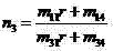


由于投影到线阵图像上的那条直径与世界坐标系成一个已知的角度


这样就得到了特征点的图像坐标和其对应的世界坐标,即可通过视平面方程和视线方程求解出中间参数

通过两个视线方程和一个视平面方程就可以得到线阵摄像机坐标系的中心: The center of the line camera coordinate system can be obtained by two line-of-sight equations and one line-of-sight equation:

即可求解出中心投影点


摄像机坐标系轴的定义为: The camera coordinate system axes are defined as:
(1)、以从中心投影点


(2)、以视平面的法向量为
(3)、以向量

选择通过线图像上某个点


根据法向量的定义可知通过

所以摄像机坐标系的轴的单位方向矢量为: So the unit direction vector of the axis of the camera coordinate system is:

因此,旋转矩阵

设定线阵图像中心为


因此
Claims (9)


Priority Applications (1)
| Application Number | Priority Date | Filing Date | Title |
|---|---|---|---|
| CN2013103412649A CN103440643A (en) | 2013-08-07 | 2013-08-07 | Single-linear-array camera calibration method |
Applications Claiming Priority (1)
| Application Number | Priority Date | Filing Date | Title |
|---|---|---|---|
| CN2013103412649A CN103440643A (en) | 2013-08-07 | 2013-08-07 | Single-linear-array camera calibration method |
Publications (1)
| Publication Number | Publication Date |
|---|---|
| CN103440643A true CN103440643A (en) | 2013-12-11 |
Family
ID=49694336
Family Applications (1)
| Application Number | Title | Priority Date | Filing Date |
|---|---|---|---|
| CN2013103412649A Pending CN103440643A (en) | 2013-08-07 | 2013-08-07 | Single-linear-array camera calibration method |
Country Status (1)
| Country | Link |
|---|---|
| CN (1) | CN103440643A (en) |
Cited By (11)
| Publication number | Priority date | Publication date | Assignee | Title |
|---|---|---|---|---|
| CN104008548A (en) * | 2014-06-04 | 2014-08-27 | 无锡观智视觉科技有限公司 | Feature point extraction method for vehicle-mounted around view system camera parameter calibration |
| CN104182969A (en) * | 2014-08-08 | 2014-12-03 | 河南科技大学 | Internal and external parameter calibration method of single-scanline camera |
| CN104732191A (en) * | 2013-12-23 | 2015-06-24 | 北京七鑫易维信息技术有限公司 | Device and method for achieving eye-tracking of virtual display screens by means of crossratio invariability |
| CN107169923A (en) * | 2017-06-01 | 2017-09-15 | 深圳市神州云海智能科技有限公司 | A kind of image position method, device for building drawing method and robot |
| CN107588732A (en) * | 2016-07-07 | 2018-01-16 | 苏州华兴致远电子科技有限公司 | Rail side Train Parts height measurement method and system |
| CN109389642A (en) * | 2017-08-04 | 2019-02-26 | 惠州市阿图达机电有限公司 | Vision system is to the scaling method of robot, system and has store function device |
| CN109584311A (en) * | 2018-11-30 | 2019-04-05 | Oppo广东移动通信有限公司 | Camera calibration method, device, electronic equipment and computer readable storage medium |
| CN109785381A (en) * | 2018-12-06 | 2019-05-21 | 苏州炫感信息科技有限公司 | A kind of optical inertial fusion space-location method, positioning device and positioning system |
| CN110827356A (en) * | 2018-08-14 | 2020-02-21 | 广东若铂智能机器人有限公司 | Camera rapid calibration method based on robot arm |
| CN111833404A (en) * | 2019-04-23 | 2020-10-27 | 鸿富锦精密电子(天津)有限公司 | Camera calibration system and camera calibration method |
| CN113052910A (en) * | 2019-12-27 | 2021-06-29 | 杭州海康机器人技术有限公司 | Calibration guiding method and camera device |
Citations (2)
| Publication number | Priority date | Publication date | Assignee | Title |
|---|---|---|---|---|
| CN101365144A (en) * | 2008-10-14 | 2009-02-11 | 北京信息科技大学 | Adjustment and Calibration Method of Linear Array CCD Scanning Detection System |
| CN102486869A (en) * | 2010-12-03 | 2012-06-06 | 王剑彬 | Calibration method of linear array camera |
-
2013
- 2013-08-07 CN CN2013103412649A patent/CN103440643A/en active Pending
Patent Citations (2)
| Publication number | Priority date | Publication date | Assignee | Title |
|---|---|---|---|---|
| CN101365144A (en) * | 2008-10-14 | 2009-02-11 | 北京信息科技大学 | Adjustment and Calibration Method of Linear Array CCD Scanning Detection System |
| CN102486869A (en) * | 2010-12-03 | 2012-06-06 | 王剑彬 | Calibration method of linear array camera |
Non-Patent Citations (4)
| Title |
|---|
| YAO QINGYUAN,ETAL: "Concentric Circles Calibration Method of Linear CCD Camera", 《INTERNATIONAL JOURNAL OF DIGITAL CONTENT TECHNOLOGY & ITS APPLICATIONS》 * |
| 王永强 等: "基于交比不变性的投影仪镜头畸变参数标定方法", 《测试技术学报》 * |
| 贺俊吉 等: "基于交比不变性的镜头畸变参数标定方法", 《仪器仪表学报》 * |
| 陈辉 等: "一种基于交比不变性的相机镜头畸变标定研究", 《北京机械工业学院学报》 * |
Cited By (15)
| Publication number | Priority date | Publication date | Assignee | Title |
|---|---|---|---|---|
| CN104732191B (en) * | 2013-12-23 | 2018-08-17 | 北京七鑫易维信息技术有限公司 | The devices and methods therefor of virtual display Eye-controlling focus is realized using Cross ration invariability |
| CN104732191A (en) * | 2013-12-23 | 2015-06-24 | 北京七鑫易维信息技术有限公司 | Device and method for achieving eye-tracking of virtual display screens by means of crossratio invariability |
| CN104008548A (en) * | 2014-06-04 | 2014-08-27 | 无锡观智视觉科技有限公司 | Feature point extraction method for vehicle-mounted around view system camera parameter calibration |
| CN104182969B (en) * | 2014-08-08 | 2017-01-25 | 河南科技大学 | Internal and external parameter calibration method of single-scanline camera |
| CN104182969A (en) * | 2014-08-08 | 2014-12-03 | 河南科技大学 | Internal and external parameter calibration method of single-scanline camera |
| CN107588732A (en) * | 2016-07-07 | 2018-01-16 | 苏州华兴致远电子科技有限公司 | Rail side Train Parts height measurement method and system |
| CN107588732B (en) * | 2016-07-07 | 2024-03-26 | 苏州华兴致远电子科技有限公司 | Rail side train part height measurement method and system |
| CN107169923A (en) * | 2017-06-01 | 2017-09-15 | 深圳市神州云海智能科技有限公司 | A kind of image position method, device for building drawing method and robot |
| CN109389642A (en) * | 2017-08-04 | 2019-02-26 | 惠州市阿图达机电有限公司 | Vision system is to the scaling method of robot, system and has store function device |
| CN110827356A (en) * | 2018-08-14 | 2020-02-21 | 广东若铂智能机器人有限公司 | Camera rapid calibration method based on robot arm |
| CN109584311A (en) * | 2018-11-30 | 2019-04-05 | Oppo广东移动通信有限公司 | Camera calibration method, device, electronic equipment and computer readable storage medium |
| CN109785381A (en) * | 2018-12-06 | 2019-05-21 | 苏州炫感信息科技有限公司 | A kind of optical inertial fusion space-location method, positioning device and positioning system |
| CN111833404A (en) * | 2019-04-23 | 2020-10-27 | 鸿富锦精密电子(天津)有限公司 | Camera calibration system and camera calibration method |
| CN111833404B (en) * | 2019-04-23 | 2023-10-31 | 富联精密电子(天津)有限公司 | Camera correction system and camera correction method |
| CN113052910A (en) * | 2019-12-27 | 2021-06-29 | 杭州海康机器人技术有限公司 | Calibration guiding method and camera device |
Similar Documents
| Publication | Publication Date | Title |
|---|---|---|
| CN103440643A (en) | Single-linear-array camera calibration method | |
| CN108648232B (en) | Binocular stereoscopic vision sensor integrated calibration method based on precise two-axis turntable | |
| CN109598762B (en) | High-precision binocular camera calibration method | |
| CN109859272B (en) | Automatic focusing binocular camera calibration method and device | |
| CN103776390B (en) | Multi-view-field data splicing method based on three-dimensional natural texture data scanning machine | |
| CN107274336B (en) | A panorama image stitching method for vehicle environment | |
| CN100562707C (en) | Binocular vision rotating axis calibration method | |
| TWI618640B (en) | Three dimensional printing system, and method for three dimensional printing | |
| CN102072706B (en) | Multi-camera positioning and tracking method and system | |
| CN105654476B (en) | Bi-objective determination method based on chaotic particle swarm optimization algorithm | |
| CN104657982A (en) | Calibration method for projector | |
| CN111667536A (en) | A parameter calibration method based on zoom camera depth estimation | |
| CN113160339A (en) | Projector calibration method based on Samm's law | |
| CN102567989A (en) | Space positioning method based on binocular stereo vision | |
| CN106595528A (en) | Digital speckle-based telecentric microscopic binocular stereoscopic vision measurement method | |
| CN106157246B (en) | A Fully Automatic Fast Cylindrical Panoramic Image Stitching Method | |
| CN103426168B (en) | Based on the general calibration method of common, wide-angle, the flake stereo camera of one-dimension calibration bar | |
| CN101763643A (en) | Automatic calibration method for structured light three-dimensional scanner system | |
| CN114359405A (en) | Calibration method of off-axis Samm 3D line laser camera | |
| CN102376089A (en) | Target correction method and system | |
| CN104732539A (en) | Projector calibration method | |
| CN109084959B (en) | An Optical Axis Parallelism Correction Method Based on Binocular Ranging Algorithm | |
| CN102810205A (en) | Method for calibrating camera shooting or photographing device | |
| CN106952219B (en) | Image generation method for correcting fisheye camera based on external parameters | |
| CN112489141B (en) | Production line calibration method and device for single-board single-image strip relay lens of vehicle-mounted camera |
Legal Events
| Date | Code | Title | Description |
|---|---|---|---|
| C06 | Publication | ||
| PB01 | Publication | ||
| C10 | Entry into substantive examination | ||
| SE01 | Entry into force of request for substantive examination | ||
| RJ01 | Rejection of invention patent application after publication |
Application publication date: 20131211 |
|
| RJ01 | Rejection of invention patent application after publication |