CN103339539A - Apparatus for producing optical fiber, method for producing optical fiber, and optical fiber produced by the method - Google Patents
Apparatus for producing optical fiber, method for producing optical fiber, and optical fiber produced by the method Download PDFInfo
- Publication number
- CN103339539A CN103339539A CN2012800069557A CN201280006955A CN103339539A CN 103339539 A CN103339539 A CN 103339539A CN 2012800069557 A CN2012800069557 A CN 2012800069557A CN 201280006955 A CN201280006955 A CN 201280006955A CN 103339539 A CN103339539 A CN 103339539A
- Authority
- CN
- China
- Prior art keywords
- light
- optical fiber
- nozzle
- photocurable composition
- light irradiation
- Prior art date
- Legal status (The legal status is an assumption and is not a legal conclusion. Google has not performed a legal analysis and makes no representation as to the accuracy of the status listed.)
- Pending
Links
Images


Classifications
-
- G—PHYSICS
- G02—OPTICS
- G02B—OPTICAL ELEMENTS, SYSTEMS OR APPARATUS
- G02B6/00—Light guides; Structural details of arrangements comprising light guides and other optical elements, e.g. couplings
-
- B—PERFORMING OPERATIONS; TRANSPORTING
- B29—WORKING OF PLASTICS; WORKING OF SUBSTANCES IN A PLASTIC STATE IN GENERAL
- B29D—PRODUCING PARTICULAR ARTICLES FROM PLASTICS OR FROM SUBSTANCES IN A PLASTIC STATE
- B29D11/00—Producing optical elements, e.g. lenses or prisms
- B29D11/00663—Production of light guides
-
- B—PERFORMING OPERATIONS; TRANSPORTING
- B29—WORKING OF PLASTICS; WORKING OF SUBSTANCES IN A PLASTIC STATE IN GENERAL
- B29C—SHAPING OR JOINING OF PLASTICS; SHAPING OF MATERIAL IN A PLASTIC STATE, NOT OTHERWISE PROVIDED FOR; AFTER-TREATMENT OF THE SHAPED PRODUCTS, e.g. REPAIRING
- B29C35/00—Heating, cooling or curing, e.g. crosslinking or vulcanising; Apparatus therefor
- B29C35/02—Heating or curing, e.g. crosslinking or vulcanizing during moulding, e.g. in a mould
- B29C35/08—Heating or curing, e.g. crosslinking or vulcanizing during moulding, e.g. in a mould by wave energy or particle radiation
- B29C35/0805—Heating or curing, e.g. crosslinking or vulcanizing during moulding, e.g. in a mould by wave energy or particle radiation using electromagnetic radiation
-
- B—PERFORMING OPERATIONS; TRANSPORTING
- B29—WORKING OF PLASTICS; WORKING OF SUBSTANCES IN A PLASTIC STATE IN GENERAL
- B29C—SHAPING OR JOINING OF PLASTICS; SHAPING OF MATERIAL IN A PLASTIC STATE, NOT OTHERWISE PROVIDED FOR; AFTER-TREATMENT OF THE SHAPED PRODUCTS, e.g. REPAIRING
- B29C35/00—Heating, cooling or curing, e.g. crosslinking or vulcanising; Apparatus therefor
- B29C35/02—Heating or curing, e.g. crosslinking or vulcanizing during moulding, e.g. in a mould
- B29C35/08—Heating or curing, e.g. crosslinking or vulcanizing during moulding, e.g. in a mould by wave energy or particle radiation
- B29C35/10—Heating or curing, e.g. crosslinking or vulcanizing during moulding, e.g. in a mould by wave energy or particle radiation for articles of indefinite length
-
- C—CHEMISTRY; METALLURGY
- C08—ORGANIC MACROMOLECULAR COMPOUNDS; THEIR PREPARATION OR CHEMICAL WORKING-UP; COMPOSITIONS BASED THEREON
- C08F—MACROMOLECULAR COMPOUNDS OBTAINED BY REACTIONS ONLY INVOLVING CARBON-TO-CARBON UNSATURATED BONDS
- C08F2/00—Processes of polymerisation
- C08F2/46—Polymerisation initiated by wave energy or particle radiation
- C08F2/48—Polymerisation initiated by wave energy or particle radiation by ultraviolet or visible light
-
- B—PERFORMING OPERATIONS; TRANSPORTING
- B29—WORKING OF PLASTICS; WORKING OF SUBSTANCES IN A PLASTIC STATE IN GENERAL
- B29C—SHAPING OR JOINING OF PLASTICS; SHAPING OF MATERIAL IN A PLASTIC STATE, NOT OTHERWISE PROVIDED FOR; AFTER-TREATMENT OF THE SHAPED PRODUCTS, e.g. REPAIRING
- B29C35/00—Heating, cooling or curing, e.g. crosslinking or vulcanising; Apparatus therefor
- B29C35/02—Heating or curing, e.g. crosslinking or vulcanizing during moulding, e.g. in a mould
- B29C35/08—Heating or curing, e.g. crosslinking or vulcanizing during moulding, e.g. in a mould by wave energy or particle radiation
- B29C35/0805—Heating or curing, e.g. crosslinking or vulcanizing during moulding, e.g. in a mould by wave energy or particle radiation using electromagnetic radiation
- B29C2035/0827—Heating or curing, e.g. crosslinking or vulcanizing during moulding, e.g. in a mould by wave energy or particle radiation using electromagnetic radiation using UV radiation
-
- B—PERFORMING OPERATIONS; TRANSPORTING
- B29—WORKING OF PLASTICS; WORKING OF SUBSTANCES IN A PLASTIC STATE IN GENERAL
- B29C—SHAPING OR JOINING OF PLASTICS; SHAPING OF MATERIAL IN A PLASTIC STATE, NOT OTHERWISE PROVIDED FOR; AFTER-TREATMENT OF THE SHAPED PRODUCTS, e.g. REPAIRING
- B29C35/00—Heating, cooling or curing, e.g. crosslinking or vulcanising; Apparatus therefor
- B29C35/02—Heating or curing, e.g. crosslinking or vulcanizing during moulding, e.g. in a mould
- B29C35/08—Heating or curing, e.g. crosslinking or vulcanizing during moulding, e.g. in a mould by wave energy or particle radiation
- B29C35/0805—Heating or curing, e.g. crosslinking or vulcanizing during moulding, e.g. in a mould by wave energy or particle radiation using electromagnetic radiation
- B29C2035/0838—Heating or curing, e.g. crosslinking or vulcanizing during moulding, e.g. in a mould by wave energy or particle radiation using electromagnetic radiation using laser
-
- G—PHYSICS
- G02—OPTICS
- G02B—OPTICAL ELEMENTS, SYSTEMS OR APPARATUS
- G02B6/00—Light guides; Structural details of arrangements comprising light guides and other optical elements, e.g. couplings
- G02B6/02—Optical fibres with cladding with or without a coating
- G02B6/02033—Core or cladding made from organic material, e.g. polymeric material
Landscapes
- Health & Medical Sciences (AREA)
- Physics & Mathematics (AREA)
- Toxicology (AREA)
- Chemical & Material Sciences (AREA)
- Thermal Sciences (AREA)
- Oral & Maxillofacial Surgery (AREA)
- Engineering & Computer Science (AREA)
- General Physics & Mathematics (AREA)
- Optics & Photonics (AREA)
- Electromagnetism (AREA)
- Organic Chemistry (AREA)
- Polymers & Plastics (AREA)
- Medicinal Chemistry (AREA)
- Chemical Kinetics & Catalysis (AREA)
- Manufacturing & Machinery (AREA)
- Ophthalmology & Optometry (AREA)
- Mechanical Engineering (AREA)
- Optical Fibers, Optical Fiber Cores, And Optical Fiber Bundles (AREA)
- Polymerisation Methods In General (AREA)
- Surface Treatment Of Glass Fibres Or Filaments (AREA)
Abstract
本发明提供一种光纤制造装置,其为通过对光固化性组合物照射光使其固化来制造光纤的装置,其特征在于,具备用于喷出光固化性组合物的喷嘴和用于对从所述喷嘴喷出的丝状的光固化性组合物照射光的光照射装置,还具备用于将所述喷嘴的喷出口处的光照射强度设定为0.2mW/cm2以下的控制装置。所述喷嘴优选为具有外管和配置于该外管的内侧的内管的双重管喷嘴。

This invention provides an optical fiber manufacturing apparatus for manufacturing optical fibers by curing a photocurable composition by irradiating it with light. The apparatus is characterized by comprising a nozzle for ejecting the photocurable composition and a light irradiation device for irradiating the filamentous photocurable composition ejected from the nozzle with light. It also comprises a control device for setting the light irradiation intensity at the nozzle outlet to 0.2 mW/ cm² or less. The nozzle is preferably a double-tube nozzle having an outer tube and an inner tube disposed inside the outer tube.
Description
技术领域technical field
本发明涉及光纤制造装置。更详细而言,涉及通过对光固化性组合物照射光使其固化来进行纺丝的光纤制造装置。另外,本发明涉及通过对光固化性组合物照射光使其固化来进行纺丝的光纤制造方法。进而,本发明涉及通过上述制造方法而制造的光纤。The present invention relates to optical fiber manufacturing apparatus. More specifically, it relates to an optical fiber manufacturing apparatus that performs spinning by irradiating a photocurable composition with light to cure it. In addition, the present invention relates to a method of manufacturing an optical fiber by irradiating a photocurable composition with light to cure it and spinning it. Furthermore, the present invention relates to an optical fiber manufactured by the above-mentioned manufacturing method.
背景技术Background technique
目前,已知芯和包层均由树脂(塑料)形成的光纤(塑料光纤)。这样的光纤轻量且挠性优异,因此,操作简便,且相对廉价,因此,被广泛利用。近年来,伴随使用光纤的场合及用途扩大,上述塑料光纤要求更高的耐热性。作为耐热性高的塑料光纤,已知例如使光固化性树脂固化而得到的光纤等。Conventionally, an optical fiber (plastic optical fiber) in which both the core and the cladding are formed of resin (plastic) is known. Such an optical fiber is light in weight and excellent in flexibility, so it is easy to handle and relatively inexpensive, so it is widely used. In recent years, with the expansion of the occasions and applications in which optical fibers are used, higher heat resistance has been demanded for the above-mentioned plastic optical fibers. As a plastic optical fiber with high heat resistance, for example, an optical fiber obtained by curing a photocurable resin is known.
作为上述塑料光纤的制造方法,在专利文献1中公开了通过照射紫外光使光固化性树脂(阳离子固化性树脂)一边反应一边进行纤维化的制造方法。在该制造方法中,将加入了紫外线固化剂的液态环氧树脂放入通常的拉丝装置的加热容器中,为了使树脂容易从拉丝用喷嘴中流出且形成一定的线径,需要通过加热器一直加热至一定的温度而使粘度降低。另外,上述制造方法是首先制备作为光导通部的芯,然后在该芯表面包覆作为保护层的包层的方法。As a method for producing the above-mentioned plastic optical fiber,
现有技术文献prior art literature
专利文献patent documents
专利文献1:日本特开昭61-245109号公报Patent Document 1: Japanese Patent Application Laid-Open No. 61-245109
发明内容Contents of the invention
发明要解决的问题The problem to be solved by the invention
但是,已经得知:在上述专利文献1中记载的制造方法中,仅仅通过加热器将光固化性树脂(阳离子固化性树脂)一直加热至一定温度使粘度减低并不能将制造的光纤的线径控制为恒定,进一步地,由于频繁地发生断线(光纤的断裂),因此,无法连续地对光纤进行纺丝。However, it has been found that in the production method described in the above-mentioned
在本发明中,发现光纤的线径无法恒定的主要原因在于,从喷嘴前端喷出的光固化性组合物(例如,含有光固化性树脂作为必需成分的组合物等)的粘度不稳定。已经得知,上述光固化性组合物的粘度不稳定的原因在于,紫外光照射于喷嘴前端,光固化性组合物发生部分固化。需要说明的是,在上述专利文献1中,完全未考虑防止从紫外光光源漏出的光照射于喷嘴附近、减少在流下的材料内部传输而到达喷嘴前端附近的紫外光的方法。In the present invention, it was found that the main reason why the fiber diameter cannot be kept constant is that the viscosity of the photocurable composition (for example, a composition containing a photocurable resin as an essential component) discharged from the tip of the nozzle is not stable. It is known that the reason why the viscosity of the photocurable composition is unstable is that the photocurable composition is partially cured when ultraviolet light is irradiated on the tip of the nozzle. It should be noted that, in the above-mentioned
另外,通常光纤与光源器件等连接而使用,因此,光纤的芯和包层的中心(中心轴)需要精度良好地吻合。然而,如上述专利文献1中记载的制造方法那样,在制作芯后、在该芯上包覆包层的方法,难以制造芯和包层的中心吻合的光纤。In addition, since an optical fiber is usually used while being connected to a light source device or the like, the center (central axis) of the core of the optical fiber and the cladding need to match with high precision. However, it is difficult to manufacture an optical fiber in which the centers of the core and the clad are aligned in the method of producing a core and then coating the core as in the production method described in
因此,本发明的目的在于提供光纤制造装置,其通过对光固化性组合物照射光使其固化来制造光纤,该装置可以得到恒定线径的光纤,且可以连续地进行纺丝而不发生断线。Therefore, it is an object of the present invention to provide an optical fiber manufacturing apparatus which manufactures an optical fiber by irradiating a photocurable composition with light to cure it, the apparatus can obtain an optical fiber with a constant diameter, and can continuously spin without interruption. Wire.
另外,本发明的其它目的在于提供光纤的制造方法,该方法包括:从喷嘴喷出光固化性组合物,并对上述光固化性组合物照射光使其固化,从而制造光纤,该制造方法可以得到恒定线径的光纤,并可以连续地进行纺丝而不发生断线。In addition, another object of the present invention is to provide a method for manufacturing an optical fiber, which includes: ejecting a photocurable composition from a nozzle, and irradiating the photocurable composition with light to cure it, thereby manufacturing an optical fiber. Obtain an optical fiber with a constant wire diameter, and it can be spun continuously without breaking the wire.
另外,本发明的其它目的在于提供通过上述制造方法制造的、具有恒定线径且生产率优异的光纤。In addition, another object of the present invention is to provide an optical fiber having a constant wire diameter and excellent productivity produced by the above-mentioned production method.
解决问题的方法way of solving the problem
本发明人等发现,在通过对光固化性组合物照射光使其固化来制造光纤时,通过将喷出上述光固化性组合物的喷嘴的前端部分(喷出口)处的光照射强度控制为特定范围,可以以恒定的线径连续地进行纺丝且不会发生断线,从而完成了本发明。The inventors of the present invention have found that when an optical fiber is produced by irradiating a photocurable composition with light to cure it, by controlling the intensity of light irradiation at the tip portion (discharge port) of the nozzle from which the photocurable composition is ejected to In a specific range, spinning can be performed continuously with a constant wire diameter without occurrence of wire breakage, and the present invention has been completed.
即,本发明提供光纤制造装置,其通过对光固化性组合物照射光使其固化来制造光纤,其特征在于:That is, the present invention provides an optical fiber manufacturing apparatus for manufacturing an optical fiber by irradiating a photocurable composition with light to cure it, characterized in that:
具备用于喷出光固化性组合物的喷嘴、和用于对由所述喷嘴喷出的丝状光固化性组合物照射光的光照射装置,having a nozzle for ejecting a photocurable composition, and a light irradiation device for irradiating light to the filamentous photocurable composition ejected from the nozzle,
该装置还具备用于将所述喷嘴的喷出口处的光照射强度设定为0.2mW/cm2以下的控制装置。The device further includes a control device for setting the light irradiation intensity at the discharge outlet of the nozzle to 0.2 mW/cm 2 or less.
另外,本发明提供上述的光纤制造装置,其中,所述喷嘴为具有外管和设置于该外管的内侧的内管的双重管喷嘴。In addition, the present invention provides the optical fiber manufacturing apparatus described above, wherein the nozzle is a double-tube nozzle having an outer tube and an inner tube provided inside the outer tube.
另外,提供上述的光纤制造装置,其中,对θ进行控制,使得其满足下述式(I)的关系,所述θ是从所述光照射装置射出的光线中照射强度达到最大的光线方向与垂直于光固化性组合物喷出方向的面所成的角度的最小值,In addition, the above-mentioned optical fiber manufacturing device is provided, wherein θ is controlled so that it satisfies the relationship of the following formula (I), and the θ is the direction of the light rays with the maximum irradiation intensity among the light rays emitted from the light irradiation device and The minimum value of the angle formed by the plane perpendicular to the ejection direction of the photocurable composition,
式(I)中,
另外,本发明提供光纤的制造方法,其通过对光固化性组合物照射光使其固化来制造光纤,该方法包括:In addition, the present invention provides a method for producing an optical fiber, which comprises:
使用喷嘴喷出光固化性组合物,接着使用光照射装置对从所述喷嘴喷出的丝状光固化性组合物照射光的工序,在所述工序中,将所述喷嘴的喷出口处的光照射强度控制为0.2mW/cm2以下。A photocurable composition is ejected using a nozzle, followed by a step of irradiating light to the filamentous photocurable composition ejected from the nozzle using a light irradiation device. Light irradiation intensity is controlled below 0.2mW/cm 2 .
另外,提供上述光纤的制造方法,其中,使用具有外管和配置于该外管内侧的内管的双重管喷嘴作为所述喷嘴,由此制造具有芯-包层结构的光纤。In addition, there is provided a method of manufacturing an optical fiber as described above, wherein an optical fiber having a core-clad structure is manufactured by using a double-tube nozzle having an outer tube and an inner tube disposed inside the outer tube as the nozzle.
进而,提供上述的光纤的制造方法,其中,对所述光固化性组合物照射光,并使得θ满足下述式(I)的关系,所述θ是从所述光照射装置射出的光线中照射强度达到最大的光线方向与垂直于光固化性组合物喷出方向的面所成的角度的最小值,Furthermore, there is provided the above-mentioned method for producing an optical fiber, wherein the photocurable composition is irradiated with light such that θ satisfies the relationship of the following formula (I), where θ is the light emitted from the light irradiation device The minimum value of the angle formed by the light direction where the irradiation intensity reaches the maximum and the surface perpendicular to the ejection direction of the photocurable composition,

式(I)中,
另外,本发明提供通过上述制造方法所制造的光纤。In addition, the present invention provides an optical fiber manufactured by the above-mentioned manufacturing method.
发明效果Invention effect
本发明的光纤制造装置由于具有上述构成,因此,可以以光固化性组合物作为原料容易地制造线径恒定的光纤,可以在制造时连续地进行纺丝而不发生断线。另外,通过将在室温下为液体的光固化性组合物作为原料,容易通过过滤减少杂质,可以得到高品质的光纤。Since the optical fiber manufacturing apparatus of the present invention has the above configuration, it is possible to easily manufacture an optical fiber with a constant diameter using the photocurable composition as a raw material, and it is possible to continuously perform spinning without disconnection during manufacture. In addition, by using a photocurable composition that is liquid at room temperature as a raw material, impurities can be easily reduced by filtration, and high-quality optical fibers can be obtained.
另外,根据本发明的光纤制造方法,可以以光固化性组合物作为原料容易地制造线径恒定的光纤,可以在制造时连续地进行纺丝而不发生断线。In addition, according to the method for producing an optical fiber of the present invention, an optical fiber having a constant diameter can be easily produced using the photocurable composition as a raw material, and spinning can be performed continuously during production without occurrence of disconnection.
另外,本发明的光纤由于通过上述制造方法制造,因此,具有恒定的线径,生产率优异,在品质方面及成本方面有利。另外,耐热性也优异。In addition, since the optical fiber of the present invention is produced by the above-mentioned production method, it has a constant wire diameter, is excellent in productivity, and is advantageous in terms of quality and cost. In addition, it is also excellent in heat resistance.
附图说明Description of drawings
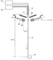
图1是表示本发明的光纤制造装置、及使用该制造装置制造光纤的一个实施方式的概略图;FIG. 1 is a schematic diagram showing an optical fiber manufacturing apparatus of the present invention and an embodiment of an optical fiber manufactured using the manufacturing apparatus;
图2是表示本发明的光纤制造装置中双重管喷嘴的一个例子的概略图(立体图);Fig. 2 is a schematic view (perspective view) showing an example of a double pipe nozzle in the optical fiber manufacturing apparatus of the present invention;
图3是表示本发明的光纤制造装置中双重管喷嘴的一个例子的概略图(图2中的A-A剖面图);Fig. 3 is a schematic view (A-A sectional view in Fig. 2 ) showing an example of a double pipe nozzle in the optical fiber manufacturing apparatus of the present invention;
图4是表示本发明的光纤制造装置中具有位置调整机构的双重管喷嘴的一个例子的概略图(双重管喷嘴的径向的剖面图);4 is a schematic diagram showing an example of a double-pipe nozzle having a position adjustment mechanism in the optical fiber manufacturing apparatus of the present invention (a radial cross-sectional view of the double-pipe nozzle);
图5是表示本发明的光纤制造装置中光照射装置的一个例子的概略图(平面图、从3个方向照射的情况);5 is a schematic diagram (plan view, the case of irradiation from three directions) showing an example of the light irradiation device in the optical fiber manufacturing apparatus of the present invention;
图6是表示本发明的光纤制造装置中光照射装置的一个例子的概略图(平面图、从2个方向照射的情况);Fig. 6 is a schematic diagram (plan view, case of irradiation from two directions) showing an example of the light irradiation device in the optical fiber manufacturing apparatus of the present invention;
图7是表示本发明的光纤制造装置中遮光筒的一个例子的概略图(立体图);Fig. 7 is a schematic view (perspective view) showing an example of a light-shielding cylinder in the optical fiber manufacturing apparatus of the present invention;
图8是表示本发明的光纤制造装置中遮光板(圆板状遮光板)的一个例子的概略图(立体图);Fig. 8 is a schematic view (perspective view) showing an example of a light-shielding plate (disc-shaped light-shielding plate) in the optical fiber manufacturing apparatus of the present invention;
图9是表示本发明的光纤制造装置中遮光板(圆锥状遮光板)的一个例子的概略图(立体图);9 is a schematic view (perspective view) showing an example of a light shield (conical light shield) in the optical fiber manufacturing apparatus of the present invention;
图10是对从光照射装置射出的光的张角
图11是对照射强度达到最大的光线的方向和垂直于光固化性组合物喷出方向的面所成的角度θ、与光的张角

图12是表示本发明的光纤制造装置中具有照射角度调整机构的光照射装置的一个例子的概略图(侧面图);12 is a schematic view (side view) showing an example of a light irradiation device having an irradiation angle adjustment mechanism in the optical fiber manufacturing apparatus of the present invention;
图13是表示本发明的光纤制造装置、及使用该制造装置制造光纤的一个实施方式(落射方式的情况)的概略图;FIG. 13 is a schematic diagram showing an optical fiber manufacturing apparatus of the present invention and an embodiment (in the case of a fall-beam method) for manufacturing an optical fiber using the manufacturing apparatus;
图14是表示实施例1及实施例2中使用的光纤制造装置(本发明的光纤制造装置)的概略图;Fig. 14 is a schematic view showing an optical fiber manufacturing apparatus (an optical fiber manufacturing apparatus of the present invention) used in Examples 1 and 2;
图15是表示比较例1中使用的光纤制造装置的概略图。FIG. 15 is a schematic diagram showing an optical fiber manufacturing apparatus used in Comparative Example 1. FIG.
符号说明Symbol Description
1 喷嘴(双重管喷嘴)1 nozzle (double tube nozzle)
11 喷出口11 ejection port
12 外管12 outer tube
13 内管13 inner tube
14 调整用螺钉14 Adjustment screws
2 光固化性组合物2 Photocurable composition
21 光固化性组合物通过的位置21 The position where the photocurable composition passes
3 光纤3 optical fiber
4 光照射装置4 light irradiation device
41 光波导的前端部分41 The front part of the optical waveguide
42 光波导42 Optical waveguide
43 光源装置43 light source device
44 基座(支承体)44 base (support body)
45 基座(支承体)45 base (support body)
46 照射角度调整机构46 Irradiation angle adjustment mechanism
47 反射镜47 reflector
48 聚光透镜48 condenser lens
51 遮光筒51 shade tube
52 遮光板52 visor
53 用于使光固化性组合物通过的孔53 holes for passing the photocurable composition
54 遮光环54 shading ring
61 最大强度光61 max intensity light
62 照射强度为最大强度光的3%的光线62 Light with an intensity of 3% of the maximum light intensity
63 张角
71 定量泵(用于输送芯剂液)71 Quantitative pump (for transporting core agent liquid)
72 定量泵(用于输送包层剂液)72 Quantitative pump (for transporting coating agent liquid)
8 卷绕装置8 winding device
具体实施方式Detailed ways
本发明的光纤制造装置是通过对光固化性组合物照射光使其固化来制造光纤(纺丝)的光纤制造装置。即,通过本发明的光纤制造装置所制造的光纤为由光固化性组合物的固化物(树脂固化物)构成的光纤。The optical fiber manufacturing apparatus of the present invention is an optical fiber manufacturing apparatus for manufacturing (spinning) an optical fiber by irradiating a photocurable composition with light to cure it. That is, the optical fiber manufactured by the optical fiber manufacturing apparatus of the present invention is an optical fiber composed of a cured product (resin cured product) of the photocurable composition.
[光固化性组合物][Photocurable composition]
上述光固化性组合物是通过照射光来进行固化而提供树脂固化物的组合物。作为上述光固化性组合物,例如可以使用通过照射光而迅速固化的公知惯用的光固化性组合物(自由基聚合性组合物、阳离子聚合性组合物、阴离子聚合性组合物等)、或者后述的特定的光固化性组合物等。其中,上述光固化性组合物优选为通过照射紫外线来进行固化的紫外线固化性组合物。The above-mentioned photocurable composition is a composition that cures by irradiating light to provide a cured resin. As the above-mentioned photocurable composition, for example, a known and commonly used photocurable composition (radical polymerizable composition, cationic polymerizable composition, anionic polymerizable composition, etc.) that is rapidly cured by irradiation with light, or a later The specific photocurable composition etc. mentioned above. Among them, the above-mentioned photocurable composition is preferably an ultraviolet curable composition cured by irradiation with ultraviolet rays.
上述光固化性组合物在室温(约25℃)为液体。即,在室温具有流动性的液态物。通过将上述光固化性组合物用作光纤的原料,可以在室温下进行纺丝而不必通过加热或使用溶剂来降低粘度。进而,可以通过过滤容易地除去光固化性组合物中的杂质,因此,容易得到高品质的光纤。另一方面,若以室温为固体的组合物(树脂组合物)作为光纤的原料,则如果不通过加热或使用溶剂使粘度降低就难以在室温进行纺丝,在成本方面是不利的。另外,通常,就在室温为固体的组合物(树脂组合物)而言,除去其中的杂质的操作非常繁杂。The above-mentioned photocurable composition is liquid at room temperature (about 25° C.). That is, liquid substances that are fluid at room temperature. By using the above photocurable composition as a raw material for an optical fiber, spinning can be performed at room temperature without reducing the viscosity by heating or using a solvent. Furthermore, since impurities in the photocurable composition can be easily removed by filtration, it is easy to obtain a high-quality optical fiber. On the other hand, if a composition (resin composition) that is solid at room temperature is used as a raw material for an optical fiber, spinning at room temperature is difficult unless the viscosity is lowered by heating or using a solvent, which is disadvantageous in terms of cost. In addition, generally, in the case of a solid composition (resin composition) at room temperature, the operation of removing impurities therein is very complicated.
上述光固化性组合物在25℃的粘度只要可从喷嘴喷出即可,没有特别限定,优选为10000~500000cP,更优选为10000~100000cP,进一步优选为50000~70000cP。在25℃的粘度低于10000cP时,存在从喷嘴喷出的光固化性组合物容易成为液滴状、不易纺丝的倾向。另一方面,在25℃的粘度超过500000cP时,有时为了使之从喷嘴喷出而需要通过加热或使用溶剂使粘度降低。需要说明的是,上述在25℃的粘度例如可以使用E型粘度计(商品名“VISCONIC”、(株)Tokimec制造)进行测定(转子:1°34’×R24、转数:0.5rpm、测定温度:25℃)。The viscosity of the photocurable composition at 25° C. is not particularly limited as long as it can be ejected from a nozzle, but is preferably 10,000 to 500,000 cP, more preferably 10,000 to 100,000 cP, and even more preferably 50,000 to 70,000 cP. When the viscosity at 25° C. is lower than 10000 cP, the photocurable composition discharged from the nozzle tends to be droplet-like and spinning tends to be difficult. On the other hand, when the viscosity at 25° C. exceeds 500,000 cP, it may be necessary to lower the viscosity by heating or using a solvent in order to discharge it from a nozzle. In addition, the above-mentioned viscosity at 25°C can be measured, for example, using an E-type viscometer (trade name "VISCONIC", manufactured by Tokimec Co., Ltd.) (rotor: 1 ° 34' × R24, number of revolutions: 0.5 rpm, measurement temperature: 25°C).
[光纤制造装置][Optical fiber manufacturing device]
本发明的光纤制造装置的特征在于,其具备用于喷出光固化性组合物的喷嘴、和用于对由所述喷嘴喷出的丝状光固化性组合物照射光的光照射装置;其还具备用于将所述喷嘴的喷出口处的光照射强度设定为0.2mW/cm2以下的控制装置。以下,根据需要参照附图对本发明的光纤制造装置进行说明。The optical fiber manufacturing apparatus of the present invention is characterized in that it includes a nozzle for ejecting the photocurable composition, and a light irradiation device for irradiating light to the filamentous photocurable composition ejected from the nozzle; A control device for setting the light irradiation intensity at the discharge outlet of the nozzle to 0.2 mW/cm 2 or less is also provided. Hereinafter, the optical fiber manufacturing apparatus of the present invention will be described with reference to the drawings as necessary.
图1为表示本发明的光纤制造装置、及使用该制造装置制造光纤的一个实施方式的概略图。在图1中,本发明的光纤制造装置由喷嘴1和光照射装置4构成,所述光照射装置按照在该喷嘴1的前端部分的喷出口11下方射出光的方式配置。需要说明的是,图1中的光照射装置4由输出光的光源装置43、传送该光的光波导42及从端部(输出端)射出光的光波导前端部41构成。需要说明的是,图1的右侧的光照射装置在绘图时省略了光波导的一部分和光源装置,但表示与左侧的光照射装置4相同的装置,并且在其它的附图中也相同。另外,图1中的51及52表示后述的遮光部件(51:遮光筒、52:遮光板),所述遮光部件用作将喷嘴1的喷出口11处的光照射强度控制在0.2mW/cm2以下的控制装置。FIG. 1 is a schematic diagram showing an optical fiber manufacturing apparatus of the present invention and an embodiment of optical fibers manufactured using the manufacturing apparatus. In FIG. 1 , the optical fiber manufacturing apparatus of the present invention is composed of a
在使用图1的光纤制造装置来制造光纤时,首先,从喷嘴1的喷出口11向垂直方向下方喷出光固化性组合物2,接着利用光照射装置4对从喷嘴1垂下的该光固化性组合物2照射光。由此,光固化性组合物2固化,得到光纤3。When using the optical fiber manufacturing device of FIG. 1 to manufacture an optical fiber, at first, the
(喷嘴)(nozzle)
本发明的光纤制造装置中的喷嘴担负在其内侧流通光固化性组合物液且从喷出口喷出的作用。从上述喷嘴的喷出口喷出的光固化性组合物通常形成为具有细径的丝状(纤维状)。The nozzle in the optical fiber manufacturing apparatus of the present invention plays the role of flowing the photocurable composition liquid inside and ejecting it from the ejection port. The photocurable composition ejected from the ejection port of the nozzle is usually formed into a filament (fibrous shape) having a small diameter.
上述喷嘴具有筒状(中空的柱状)的形状,在其前端(一侧端部)具有用于喷出光固化性组合物的喷出口。上述喷嘴中相对于喷出口相反侧的端部没有特别限定,通常根据需要经由适宜的管与储存光固化性组合物的罐或定量泵等连接。The nozzle has a cylindrical (hollow columnar) shape, and has an outlet for ejecting the photocurable composition at its tip (one side end). The end of the nozzle on the opposite side to the discharge port is not particularly limited, and is usually connected to a tank or a metered pump storing the photocurable composition via an appropriate tube as necessary.
上述喷嘴的形状只要为筒状即可,没有特别限定,例如可以为圆筒状,也可以为棱筒状。其中,从制作低传输损耗的光纤的观点考虑,优选圆筒状。The shape of the nozzle is not particularly limited as long as it is cylindrical, and may be, for example, cylindrical or rectangular. Among them, a cylindrical shape is preferable from the viewpoint of producing an optical fiber with low transmission loss.
上述喷嘴的材质没有特别限定,例如可以举出:SUS、铝、树脂等。其中,从耐久性、强度的观点考虑,优选SUS。The material of the said nozzle is not specifically limited, For example, SUS, aluminum, resin, etc. are mentioned. Among them, SUS is preferable from the viewpoint of durability and strength.
从使光纤的芯和包层的中心一致的观点考虑,上述喷嘴特别优选为具有外管和配置于该外管内侧的内管的双重管喷嘴。更详细而言,所谓上述双重管喷嘴为具有双重管结构的喷嘴,所述双重管结构是在筒状(特别是圆筒状)的外管内侧配置具有比该外管内径更小的外径的筒状(特别是圆筒状)内管而形成的结构。图2及图3为表示双重管喷嘴的一个例子的概略图,图2表示立体图,图3表示图2中的A-A剖面图。在图2及图3中,12表示外管、13表示内管。在使用这样的双重管喷嘴的情况下,在内管13的内侧流通形成芯的光固化性组合物(有时称为“芯剂”),在外管12和内管13之间流通形成包层的光固化性组合物(有时称为“包层剂”),由此,可以从喷嘴的喷出口11同时喷出芯剂和包层剂。接着,通过对这些光固化性组合物(芯剂及包层剂)照射光使其固化,可以一步制造具有芯-包层结构的光纤(芯和包层的双重(二层)结构的光纤)。From the viewpoint of aligning the center of the core and the cladding of the optical fiber, the nozzle is particularly preferably a double-tube nozzle having an outer tube and an inner tube disposed inside the outer tube. More specifically, the so-called double-pipe nozzle is a nozzle having a double-pipe structure arranged inside a cylindrical (especially cylindrical) outer pipe having an outer diameter smaller than the inner diameter of the outer pipe. The structure formed by the cylindrical (especially cylindrical) inner tube. 2 and 3 are schematic diagrams showing an example of a double pipe nozzle, FIG. 2 is a perspective view, and FIG. 3 is a cross-sectional view taken along line A-A in FIG. 2 . In FIGS. 2 and 3 , 12 denotes an outer tube, and 13 denotes an inner tube. In the case of using such a double-tube nozzle, a photocurable composition forming a core (sometimes referred to as a "core agent") flows inside the
上述双重管喷嘴中的外管径(内径及外径)、内管径(内径及外径)可根据所制造的光纤的芯径及包层径、光固化性组合物的粘度及喷出速度等适宜选择,没有特别限定。具体而言,例如上述双重管喷嘴中的外管的内径优选2~8mm,更优选2.4~5.4mm。进而,上述双重管喷嘴中,内管的外径例如优选1~7mm,更优选1.5~4mm,上述内管的内径例如优选0.6~6.4mm,更优选为1.1~3.4mm。The outer tube diameter (inner diameter and outer diameter) and the inner tube diameter (inner diameter and outer diameter) of the above-mentioned double-tube nozzle can be adjusted according to the core diameter and cladding diameter of the optical fiber to be manufactured, the viscosity and the ejection speed of the photocurable composition. It is not particularly limited and is selected as appropriate. Specifically, for example, the inner diameter of the outer tube in the above-mentioned double tube nozzle is preferably 2 to 8 mm, more preferably 2.4 to 5.4 mm. Furthermore, in the above-mentioned double tube nozzle, the outer diameter of the inner tube is preferably, for example, 1 to 7 mm, more preferably 1.5 to 4 mm, and the inner diameter of the inner tube is, for example, preferably 0.6 to 6.4 mm, and more preferably 1.1 to 3.4 mm.
上述双重管喷嘴优选至少在喷出口侧的前端部分处外管的轴(中心轴)和内管的轴(中心轴)一致。通过使用这样的双重管喷嘴,可以容易地制造芯的中心轴和包层的中心轴一致的光纤。如上所述中心轴一致的光纤在光纤之间进行连接或与其它的器件(例如连接器或光源装置等)进行连接时,可发挥高可靠性。It is preferable that the axis (central axis) of the outer tube and the axis (central axis) of the inner tube coincide at least at the front end portion on the discharge port side. By using such a double tube nozzle, an optical fiber in which the central axis of the core and the central axis of the cladding coincide can be easily produced. When the optical fibers whose central axes coincide as described above are connected between optical fibers or with other devices (for example, connectors, light source devices, etc.), high reliability can be exhibited.
为了使外管的轴和内管的轴一致,上述双重管喷嘴优选具有用于调整位于外管内侧的内管位置的调整机构(有时称为“位置调整机构”)。上述位置调整机构只要可以调整内管的位置即可,没有特别限定,例如,可以将配置成贯通外管且前端与内管的外表面接触的螺钉(调整用螺钉)作为简便的位置调整机构而使用。图4是表示具有位置调整机构的双重管喷嘴的一个例子的概略图(双重管喷嘴的径向的剖面图)。在图4中,14表示调整用螺钉。在图4中,通过使3个调整用螺钉的前端相对于内管等间隔地接触,构成位置调整机构,分别调节这些调整用螺钉的拧入情况,可以调整外管的内侧中的内管的位置。但是,使用的调整用螺钉的大小、数目、配置方法等并不限定于此。In order to make the axis of the outer tube coincide with the axis of the inner tube, the double tube nozzle preferably has an adjustment mechanism (sometimes referred to as "position adjustment mechanism") for adjusting the position of the inner tube located inside the outer tube. The above-mentioned position adjustment mechanism is not particularly limited as long as it can adjust the position of the inner tube. For example, a screw (adjustment screw) arranged to pass through the outer tube and whose tip is in contact with the outer surface of the inner tube can be used as a simple position adjustment mechanism. use. Fig. 4 is a schematic view (cross-sectional view in the radial direction of the double-pipe nozzle) showing an example of a double-pipe nozzle having a position adjustment mechanism. In FIG. 4 , 14 denotes an adjustment screw. In Fig. 4, by making the front ends of the three adjustment screws contact the inner tube at equal intervals, a position adjustment mechanism is formed, and the screwing conditions of these adjustment screws are adjusted respectively, so that the position of the inner tube in the inner side of the outer tube can be adjusted. Location. However, the size, number, arrangement method, etc. of the adjustment screws to be used are not limited thereto.
需要说明的是,本发明的光纤制造装置中的喷嘴并不限定于上述的双重管喷嘴,可以为由单管构成的喷嘴,也可以为具有三重管以上的多重管结构的喷嘴。上述喷嘴可以根据制造的光纤的结构、形状来适宜选择。It should be noted that the nozzle in the optical fiber manufacturing apparatus of the present invention is not limited to the above-mentioned double-tube nozzle, and may be a nozzle composed of a single tube, or a nozzle having a multiple-tube structure with triple or higher tubes. The above-mentioned nozzle can be appropriately selected according to the structure and shape of the optical fiber to be produced.
(光照射装置)(light irradiation device)
本发明的光纤制造装置中的光照射装置担负着对由喷嘴喷出的丝状光固化性组合物照射光并使其固化的作用。通过使由喷嘴的喷出口拉伸出的丝状光固化性组合物固化,可得到光纤。The light irradiation device in the optical fiber manufacturing apparatus of the present invention plays a role of irradiating and curing the filamentary photocurable composition discharged from the nozzle with light. An optical fiber can be obtained by curing the filamentary photocurable composition pulled out from the outlet of the nozzle.
通过上述光照射装置照射的光只要为可以使光固化性组合物固化的光即可,没有特别限定,例如可以使用紫外线、红外线、可见光线、电子束等。其中,从可以使用一般的光引发剂的观点考虑,优选紫外线。即,本发明的光纤制造装置中的光照射装置优选紫外线照射装置。The light irradiated by the above-mentioned light irradiation device is not particularly limited as long as it can cure the photocurable composition, for example, ultraviolet rays, infrared rays, visible rays, electron beams and the like can be used. Among these, ultraviolet rays are preferable from the viewpoint that general photoinitiators can be used. That is, the light irradiation device in the optical fiber manufacturing apparatus of the present invention is preferably an ultraviolet irradiation device.
上述光照射装置可以使用射出(放射)能使光固化性组合物固化的光(特别是紫外线)且能对光固化性组合物进行照射的公知惯用的光照射装置。具体而言,例如,作为射出紫外线的光照射装置(紫外线照射装置),可以使用高压水银灯、超高压水银灯、氙灯、碳弧灯、金属卤化物灯、太阳光、LED灯、激光等光源。另外,可以将这些光源和用于传送从该光源输出的光的光波导组合而成的装置、以及将其与各种光学系统(例如透镜或镜等)等组合而成的装置等用作光照射装置。As the above-mentioned light irradiation device, a known and commonly used light irradiation device capable of emitting (radiating) light (especially ultraviolet rays) capable of curing the photocurable composition and irradiating the photocurable composition can be used. Specifically, for example, light sources such as high-pressure mercury lamps, ultra-high pressure mercury lamps, xenon lamps, carbon arc lamps, metal halide lamps, sunlight, LED lamps, and lasers can be used as a light irradiation device (ultraviolet irradiation device) that emits ultraviolet rays. In addition, a device combining these light sources and an optical waveguide for transmitting light output from the light source, and a device combining it with various optical systems (such as lenses or mirrors, etc.) and the like can be used as light sources. Irradiation device.
需要说明的是,在本说明书中,有时将上述光照射装置中、特别是射出光的部分称为“射出部”。例如在图1所示的光照射装置4中,光波导的前端部分41的端部(输出端)为射出部。In addition, in this specification, among the said light irradiation apparatuses, the part which emits light especially may be called an "emission part." For example, in the light irradiation device 4 shown in FIG. 1 , the end portion (output end) of the
在本发明的光纤制造装置中,使用上述光照射装置对光固化性组合物照射光的方法没有特别限定。例如,上述光照射装置的射出部的配置及数目没有特别限定。特别优选按照可以对光固化性组合物均匀地照射光的方式来配置光照射装置的射出部。图5是表示本发明的光纤制造装置中的光照射装置的一个例子的概略图(平面图)。图5中的光照射装置是在喷嘴的喷出口下方从3个方向射出光,对光固化性组合物进行照射的光照射装置。上述光照射装置具有射出部(光波导的前端部分41的输出端),所述射出部按照相对于光固化性组合物为等距离且相互之间等间隔地进行配置。在图5中,21表示光固化性组合物通过的位置、44及45表示在本发明的光纤制造装置中用于固定光照射装置的光波导的前端部分41的基座(支承体)。但是,光照射装置并不限定于此,例如如图6所示的光照射装置那样,可以为从2个方向照射光的装置,也可以为仅从1个方向或从4个以上的方向照射光的装置等。另外,光照射装置并不限定于在喷嘴的喷出口的下方射出光的装置,也可以是从比喷嘴的喷出口更靠上方的位置射出光的装置(例如,参照图13)。In the optical fiber manufacturing apparatus of the present invention, the method of irradiating the photocurable composition with light using the light irradiation device is not particularly limited. For example, the arrangement and number of emitting units of the above-mentioned light irradiation device are not particularly limited. In particular, it is preferable to arrange the emission part of the light irradiation device so that light can be uniformly irradiated to the photocurable composition. Fig. 5 is a schematic view (plan view) showing an example of a light irradiation device in the optical fiber manufacturing apparatus of the present invention. The light irradiation device in FIG. 5 is a light irradiation device that emits light from three directions below the discharge port of the nozzle to irradiate the photocurable composition. The above-mentioned light irradiation device has an output portion (an output end of the
另外,为了对光固化性组合物有效地照射光,上述光照射装置也可以根据需要与适宜的光学系统组合使用。具体而言,例如也可以用聚光透镜(凸透镜或柱面透镜等)对来自上述光照射装置的光进行聚光从而对光固化性组合物照射强度更高的光、或利用镜(反射镜)使照射了光固化性组合物的光反射而再次对光固化性组合物进行照射。通过使用上述光学系统,可以谋求光的有效利用,可以提高光纤的生产率。作为所述光学系统,并不限定于上述,可以使用公知惯用的光学设备等中通常所使用的光学系统等。In addition, in order to efficiently irradiate the photocurable composition with light, the above-mentioned light irradiation device may be used in combination with an appropriate optical system as needed. Specifically, for example, light from the above-mentioned light irradiation device may be condensed by a condensing lens (convex lens or cylindrical lens, etc.) to irradiate the photocurable composition with higher intensity light, or a mirror (reflector mirror) may be used to condense the light from the above-mentioned light irradiation device. ) reflects the light irradiated with the photocurable composition to irradiate the photocurable composition again. By using the above-mentioned optical system, efficient use of light can be achieved, and the productivity of optical fibers can be improved. The optical system is not limited to the above, and an optical system or the like generally used in known and commonly used optical devices or the like can be used.
(控制装置)(control device)
本发明的光纤制造装置除了具备上述喷嘴和光照射装置,还具备用于将上述喷嘴的喷出口处的光照射强度(以下,有时简称为“喷出口处的光照射强度”)控制为0.2mW/cm2以下的控制装置。In addition to the above-mentioned nozzle and the light irradiation device, the optical fiber manufacturing apparatus of the present invention also includes a device for controlling the light irradiation intensity at the ejection outlet of the above-mentioned nozzle (hereinafter, sometimes simply referred to as "light irradiation intensity at the ejection outlet") to 0.2 mW/ Control devices below cm 2 .
上述所谓“喷出口处的光照射强度”是指:在本发明的光纤制造装置中,在与制造光纤时完全相同的装置结构及条件下、但不输送光固化性组合物的情况下,从光照射装置射出光时,在喷嘴的喷出口处测定的光照射强度(单位:mW/cm2)。上述照射强度的测定方法没有特别限定,例如可以使用功率计(商品名“紫外线光量计UTI-250”、USHIO电机(株)制)进行测定。The above-mentioned "light irradiation intensity at the ejection port" refers to: in the optical fiber manufacturing apparatus of the present invention, under the same device structure and conditions as in the optical fiber manufacturing, but under the situation where the photocurable composition is not transported, from Light irradiation intensity (unit: mW/cm 2 ) measured at the discharge port of the nozzle when the light irradiation device emits light. The measurement method of the said irradiation intensity is not specifically limited, For example, it can measure using a power meter (trade name "ultraviolet light meter UTI-250", manufactured by USHIO Electric Co., Ltd.).
上述喷出口处的光照射强度只要控制在0.2mW/cm2以下即可,没有特别限定,但从得到线径均匀的光纤、制造时防止断线的观点考虑,优选0.1mW/cm2以下。上述喷出口处的光照射强度超过0.2mW/cm2时,在喷嘴的前端的喷出口处会发生光固化性组合物的固化反应(聚合反应),在喷出口附近的光固化性组合物的粘度发生变动或产生堵塞。其结果,从喷嘴喷出的光固化性组合物的线径不稳定,无法得到线径恒定的光纤,或在制造时频发断线使光纤的生产率降低。The light irradiation intensity at the ejection port is not particularly limited as long as it is controlled to be 0.2 mW/cm 2 or less, but it is preferably 0.1 mW/cm 2 or less from the viewpoint of obtaining an optical fiber with a uniform diameter and preventing disconnection during manufacture. When the light irradiation intensity at the above-mentioned discharge port exceeds 0.2mW/cm 2 , the curing reaction (polymerization reaction) of the photocurable composition will occur at the discharge port at the front end of the nozzle, and the photocurable composition near the discharge port will Viscosity changes or clogging occurs. As a result, the diameter of the photocurable composition ejected from the nozzle is not stable, and an optical fiber with a constant diameter cannot be obtained, or frequent disconnection occurs during production, reducing the productivity of the optical fiber.
上述控制装置只要可以将喷出口处的光照射强度控制为0.2mW/cm2以下即可,没有特别限定。The control device is not particularly limited as long as it can control the light irradiation intensity at the discharge port to be 0.2 mW/cm 2 or less.
通过本发明的光纤制造装置制造的光纤的原料,由于是室温为液体的光固化性组合物,因此,需要在从喷嘴喷出的上述光固化性组合物可以保持丝状(纤维状)形状的较早阶段照射光使其固化。因此,本发明的光纤制造装置需要尽可能地使光固化性组合物的照射光的部分和喷嘴的喷出口的距离接近,从而必然具有对光固化性组合物照射的光容易到达喷出口附近的结构。从这样的观点考虑,作为上述控制装置,例如使用可以抑制光的扩展或配置在光照射装置的射出部和喷嘴的喷出口之间且在上述喷出口形成阴影的以下遮光部件是有效的。The raw material of the optical fiber manufactured by the optical fiber manufacturing apparatus of the present invention is a photocurable composition that is liquid at room temperature. Therefore, it is necessary to maintain a filamentary (fibrous) shape in the above-mentioned photocurable composition ejected from the nozzle. The earlier stages are cured by exposure to light. Therefore, the optical fiber manufacturing apparatus of the present invention needs to make the distance between the part of the photocurable composition irradiated with light and the discharge port of the nozzle as close as possible, so that the light irradiated to the photocurable composition must easily reach the vicinity of the discharge port. structure. From this point of view, it is effective to use, as the control device, the following light shielding member that can suppress the spread of light or that is disposed between the emission portion of the light irradiation device and the discharge port of the nozzle and casts a shadow on the discharge port.
图7表示作为上述遮光部件一个例子的筒状遮光部件51(有时称为“遮光筒”)。通过利用上述遮光筒51覆盖光照射装置的射出部(光波导前端部分41的输出端),可以防止射出的光扩散至必要范围以外,可以抑制光向喷嘴的喷出口的传输(参照图1)。上述遮光筒的直径及长度等可根据光照射装置的射出部的形状等适宜选择,没有特别限定。FIG. 7 shows a cylindrical light shielding member 51 (sometimes referred to as a "light shielding cylinder") as an example of the above light shielding member. By covering the emission portion (the output end of the optical waveguide front end portion 41) of the light irradiation device with the above-mentioned light-shielding
另外,作为上述遮光部件,可以使用能够配置在光照射装置的射出部和喷嘴的喷出口之间的板状遮光部件(有时称为“遮光板”)(参照图1,图1中的52)。通过使用这样的遮光板,可以遮蔽在使用遮光筒覆盖光照射装置的射出部的情况下仍然会漏出的较弱的光。因此,组合使用上述的遮光板及遮光筒是有效的。上述遮光板的形状及大小没有特别限定,例如可以使用图8所示的圆板状遮光板、图9所示的圆锥状遮光板等。上述遮光板从设置的容易性的观点考虑,优选具有用于使光固化性组合物通过的孔(图8、图9中的53)。In addition, as the above-mentioned light-shielding member, a plate-shaped light-shielding member (sometimes referred to as a "light-shielding plate") (refer to FIG. 1, 52 in FIG. 1 ) that can be arranged between the emission portion of the light irradiation device and the discharge port of the nozzle can be used. . By using such a light-shielding plate, it is possible to shield weak light that leaks even when the light-shielding cylinder is used to cover the emission portion of the light irradiation device. Therefore, it is effective to use the above-mentioned light-shielding plate and light-shielding tube in combination. The shape and size of the shading plate are not particularly limited, and for example, a disk-shaped shading plate shown in FIG. 8 , a conical shading plate shown in FIG. 9 , or the like can be used. From the viewpoint of ease of installation, the light shielding plate preferably has a hole ( 53 in FIGS. 8 and 9 ) for passing the photocurable composition.
形成上述遮光筒、遮光板等遮光部件的材质没有特别限定。例如可以使用SUS、铝、树脂、纸等。另外,上述遮光部件没有特别限定,但从防止光的反射的观点考虑,优选为黑色。The material forming the light-shielding members such as the above-mentioned light-shielding cylinder and the light-shielding plate is not particularly limited. For example, SUS, aluminum, resin, paper, etc. can be used. Moreover, although the said light shielding member is not specifically limited, From a viewpoint of preventing light reflection, it is preferable that it is black.
(光的照射角度的控制)(Control of the irradiation angle of light)
在本发明的光纤制造装置中,为了获得均匀线径的光纤及以更高水平得到断线的抑制等效果,优选将光对光固化性组合物的照射角度控制为特定范围。具体而言,在本发明的光纤制造装置中,优选对角度θ进行控制并使其满足下述式(I)的关系,所述角度θ是从光照射装置射出的光线中照射强度达到最大的光线方向与垂直于光固化性组合物喷出方向的面(平面)所成的角度的最小值。In the optical fiber manufacturing apparatus of the present invention, it is preferable to control the irradiation angle of light to the photocurable composition within a specific range in order to obtain an optical fiber with a uniform diameter and obtain effects such as suppression of disconnection at a higher level. Specifically, in the optical fiber manufacturing apparatus of the present invention, it is preferable to control the angle θ, which is the maximum irradiation intensity among the rays emitted from the light irradiation device, so as to satisfy the relationship of the following formula (I). The minimum value of the angle formed by the light direction and the surface (plane) perpendicular to the ejection direction of the photocurable composition.

上述式(I)中,
从上述光照射装置(光照射装置的射出部)射出的光线中,照射强度达到最大的光线(有时称为“最大强度光”)严格来讲可通过测定从射出部射出的光的光强度分布来确定。一般而言,光照射装置的射出部(例如、光波导前端部分的输出端)的正面射出的光线为最大强度光。因此,例如,将光波导的前端部分相对于与光固化性组合物喷出方向垂直的平面(通常为水平面)向光固化性组合物喷出方向侧(例如下方)倾斜角度θ,由此,可以将最大强度光的方向与垂直于光固化性组合物喷出方向的面所成的角度的最小值设为θ(例如,参照图11(a))。Among the light rays emitted from the above-mentioned light irradiation device (emission part of the light irradiation device), the light with the maximum irradiation intensity (sometimes referred to as "maximum intensity light") can be measured strictly by measuring the light intensity distribution of the light emitted from the emission part. to make sure. Generally speaking, the light emitted from the front of the emitting portion (for example, the output end of the front end portion of the optical waveguide) of the light irradiation device is the maximum intensity light. Therefore, for example, the front end portion of the optical waveguide is inclined by an angle θ to the side (for example, downward) of the photocurable composition discharge direction with respect to a plane (usually a horizontal plane) perpendicular to the photocurable composition discharge direction, thereby, The minimum value of the angle formed by the direction of the maximum intensity light and the surface perpendicular to the ejection direction of the photocurable composition can be set to θ (for example, refer to FIG. 11( a )).
上述式(I)中,

图10是对从光照射装置射出的光的张角


上述例如可以通过测定距射出部一定距离(例如1.5cm)处的光强度分布来导出。需要说明的是,光强度分布例如可以通过如下操作测定:使用紫外线光量计,将其光接收器从照射光的中心(射出部中心的正面)向周边部一点点地移动。the above For example, it can be derived by measuring the light intensity distribution at a certain distance (for example, 1.5 cm) from the emission part. The light intensity distribution can be measured, for example, by using an ultraviolet light meter and moving its photoreceptor a little from the center of the irradiated light (the front of the center of the emission part) to the peripheral part.
在本发明的光纤制造装置中,进行控制从光照射装置射出的最大强度光的方向与垂直于光固化性组合物喷出方向的面所成的角度的最小值θ并使得θ满足上述式(I)的关系,从而可以得到线径均匀的光纤以及以更高水平得到抑制制造时的断线等效果。这取决于以下原因。In the optical fiber manufacturing apparatus of the present invention, the minimum value θ of the angle formed by the direction of the maximum intensity light emitted from the light irradiation device and the plane perpendicular to the ejection direction of the photocurable composition is controlled so that θ satisfies the above formula ( I) relationship, so that it is possible to obtain an optical fiber with a uniform wire diameter and obtain effects such as suppression of disconnection during manufacturing at a higher level. This depends on the following reasons.
图11是对最大强度光的方向与垂直于光固化性组合物喷出方向的面所成的角度的最小值θ、以及光的张角


从控制光的照射角度(具体而言,最大强度光的方向与垂直于光固化性组合物喷出方向的面所成的角度的最小值θ)的观点考虑,本发明的光纤制造装置优选具有用于调整上述光照射装置的照射角度的机构(有时称为“照射角度调整机构”)。图12是表示本发明的光纤制造装置中具备照射角度调整机构的光照射装置的一个例子的概略图。在图12的光照射装置中,通过具备作为照射角度调整机构的螺钉46(角度调整用螺钉),可以自由地调整光波导的前端部分的角度。From the viewpoint of controlling the irradiation angle of light (specifically, the minimum value θ of the angle between the direction of the maximum intensity light and the plane perpendicular to the direction in which the photocurable composition is ejected), the optical fiber manufacturing apparatus of the present invention preferably has A mechanism for adjusting the irradiation angle of the above-mentioned light irradiation device (sometimes referred to as "irradiation angle adjustment mechanism"). 12 is a schematic diagram showing an example of a light irradiation device provided with an irradiation angle adjustment mechanism in the optical fiber manufacturing apparatus of the present invention. In the light irradiation device of FIG. 12 , the angle of the tip portion of the optical waveguide can be freely adjusted by including the screw 46 (angle adjustment screw) as the irradiation angle adjustment mechanism.
(其它)(other)
在本发明的光纤制造装置中,除上述的喷嘴、光照射装置、控制装置以外,例如为了控制从喷嘴喷出的光固化性组合物的量(喷出量),可以使用定量泵。通过控制光固化性组合物的喷出量,可以控制光纤的线径。通常若喷出量增多,则光固化性组合物(光纤)的线径变粗。需要说明的是,在使用双重管喷嘴的情况下,通过分别独立地控制芯剂和包层剂的喷出量,可以自由地控制得到的光纤的芯径和包层径。In the optical fiber manufacturing apparatus of the present invention, in addition to the above-mentioned nozzle, light irradiation device, and control device, for example, a metering pump can be used to control the amount of the photocurable composition ejected from the nozzle (discharge amount). By controlling the discharge amount of the photocurable composition, the wire diameter of the optical fiber can be controlled. Generally, when the ejection amount increases, the wire diameter of the photocurable composition (optical fiber) becomes thick. In the case of using a double tube nozzle, the core diameter and the cladding diameter of the obtained optical fiber can be freely controlled by controlling the ejection amounts of the core agent and the cladding agent independently.
另外,在本发明的光纤制造装置中,可以使用用于卷绕制造的光纤并回收的卷绕装置(卷绕机)。通过控制利用卷绕装置的光纤的卷绕速度,可以控制光纤的线径。通常若加快卷绕速度,则光固化性组合物(光纤)的线径变细。In addition, in the optical fiber manufacturing apparatus of the present invention, a winding device (winder) for winding the manufactured optical fiber and recovering it can be used. By controlling the winding speed of the optical fiber by the winding device, the wire diameter of the optical fiber can be controlled. Generally, when the winding speed is increased, the wire diameter of the photocurable composition (optical fiber) becomes smaller.
进而,本发明的光纤制造装置也可以根据需要具备其它的设备或装置(例如,加热单元、冷却单元、纤维径测定装置、纤维张力测定装置等)。Furthermore, the optical fiber manufacturing apparatus of the present invention may include other equipment or devices (for example, a heating unit, a cooling unit, a fiber diameter measuring device, a fiber tension measuring device, etc.) as necessary.
(光纤制造装置的其它的实施方式)(Other Embodiments of Optical Fiber Manufacturing Device)
对本发明的光纤制造装置而言,如上所述,除在喷嘴的喷出口下方配置光照射装置的射出部的实施方式(例如,参照图1)以外,也包括在喷嘴的喷出口上方配置光照射装置的射出部、且从喷出口的上方射出光的实施方式(有时将该方式的装置称为“落射方式的光纤制造装置”)。图13是表示本发明的光纤制造装置、及使用该制造装置制造光纤的一个实施方式(落射方式的情况)的概略图。图13中的本发明的光纤制造装置具备喷嘴1和光照射装置,所述光照射装置从该喷嘴1前端部分的喷出口11的上方照射光。在图13中,光照射装置的结构中除了具备输出光的光源装置43、传送该光的光波导42、及通过端部(输出端)射出光的光波导前端部41,还具备将从光波导前端部41的输出端射出的光向下方反射的反射镜47和将反射的光进行聚光的聚光透镜48。图13中的54表示环状的遮光部件(有时称为“遮光环”),通过将这样的遮光环安装于喷嘴前端的上方,可以将喷嘴1的喷出口11处的光照射强度控制在0.2mW/cm2以下。For the optical fiber manufacturing apparatus of the present invention, as described above, in addition to the embodiment (for example, refer to FIG. 1 ) in which the emission part of the light irradiation device is arranged below the ejection port of the nozzle, it also includes the arrangement of the light irradiation device above the ejection port of the nozzle. An embodiment in which light is emitted from the ejection part of the device and emitted from above the ejection port (this type of device may be referred to as "a fall-type optical fiber manufacturing device"). Fig. 13 is a schematic diagram showing an optical fiber manufacturing apparatus of the present invention and an embodiment (in the case of the epi-shot method) of manufacturing an optical fiber using the manufacturing apparatus. The optical fiber manufacturing apparatus of the present invention shown in FIG. 13 includes a
在本发明的光纤制造装置为落射方式的光纤制造装置的情况下,如图13所示那样,具有如下优点:通过使用遮光环54,容易在喷嘴的喷出口处形成阴影,可更有效地降低喷嘴的喷出口处的光照射强度。然而,由于光固化性组合物和光照射装置的射出部的距离较远,因此,具有如下缺点:不易对光固化性组合物照射高强度的光,不易提高生产率。但是,即使在落射方式的情况下,也可以通过根据需要组合使用配置在喷嘴的喷出口下方的射出部的光照射装置等来消除上述缺点。In the case where the optical fiber manufacturing apparatus of the present invention is an optical fiber manufacturing apparatus of a fall mode, as shown in FIG. 13 , it has the following advantages: by using the light-shielding
[光纤的制造方法][Manufacturing method of optical fiber]
本发明的光纤的制造方法为通过对光固化性组合物照射光使其固化来制造光纤的方法,该方法包括:使用喷嘴喷出光固化性组合物,接着使用光照射装置对从上述喷嘴喷出的丝状光固化性组合物照射光的工序,进一步地,在上述工序中,将上述喷嘴的喷出口处的光照射强度控制在0.2mW/cm2以下。The method for producing an optical fiber of the present invention is a method for producing an optical fiber by irradiating light to a photocurable composition to cure it, and the method includes: spraying a photocurable composition using a nozzle, and then spraying the photocurable composition from the nozzle using a light irradiation device. In the step of irradiating the emitted filamentary photocurable composition with light, further, in the above step, the light irradiation intensity at the discharge port of the nozzle is controlled to be 0.2 mW/cm 2 or less.
作为上述喷嘴,没有特别限定,例如可以使用上述本发明的光纤制造装置的说明中例示的喷嘴。其中,本发明的光纤制造方法优选使用具有外管和配置于该外管内侧的内管的双重管喷嘴作为上述喷嘴来制造具有芯-包层结构的光纤的方法。作为上述双重管喷嘴,可优选使用上述本发明的光纤制造装置的说明中例示的喷嘴。通过使用这样的双重管喷嘴,可以同时从喷嘴喷出芯剂和包层剂,接着,通过对这些光固化性组合物(芯剂及包层剂)照射光使其固化,可以一步制造具有芯-包层结构的光纤。The nozzle is not particularly limited, and for example, the nozzles exemplified in the description of the optical fiber manufacturing apparatus of the present invention can be used. Among them, the optical fiber manufacturing method of the present invention is preferably a method of manufacturing an optical fiber having a core-clad structure using a double-tube nozzle having an outer tube and an inner tube disposed inside the outer tube as the nozzle. As the above-mentioned double pipe nozzle, the nozzles exemplified in the description of the above-mentioned optical fiber manufacturing apparatus of the present invention can be preferably used. By using such a double-pipe nozzle, the core agent and the cladding agent can be ejected from the nozzle at the same time, and then these photocurable compositions (core agent and cladding agent) can be cured by irradiating light, and a composite material with a core can be manufactured in one step. - Optical fiber with cladding structure.
作为上述光照射装置,只要可以射出能使光固化性组合物固化的光即可,没有特别限定,例如可以使用上述的本发明的光纤制造装置的说明中例示的装置。The light irradiation device is not particularly limited as long as it can emit light capable of curing the photocurable composition. For example, the device exemplified in the above description of the optical fiber manufacturing device of the present invention can be used.
在本发明的光纤的制造方法中,首先,从上述喷嘴的喷出口喷出光固化性组合物(例如,向竖直方向下方)。此时的光固化性组合物的喷出速度(输送速度)没有特别限定,例如优选0.3~1mL/分钟,更优选0.375~0.6mL/分钟。通过控制光固化性组合物的喷出速度,可以控制光纤的线径。另外,在使用上述双重管喷嘴作为喷嘴的情况下,可以同时喷出芯剂和包层剂。此时的芯剂和包层剂的合计的喷出速度没有特别限定,例如优选为0.3~1mL/分钟,更优选为0.375~0.6mL/分钟。另外,通过分别独立地控制芯剂和包层剂的喷出速度,可以独立地控制光纤的芯径和包层直径。需要说明的是,喷出速度的控制例如可以使用上述本发明的光纤制造装置的说明中例示的定量泵等来控制。In the method of manufacturing an optical fiber of the present invention, first, the photocurable composition is ejected from the ejection port of the nozzle (for example, vertically downward). The ejection speed (transportation speed) of the photocurable composition at this time is not particularly limited, for example, it is preferably 0.3 to 1 mL/min, more preferably 0.375 to 0.6 mL/min. By controlling the ejection speed of the photocurable composition, the wire diameter of the optical fiber can be controlled. In addition, in the case of using the above-mentioned double pipe nozzle as the nozzle, the core agent and the cladding agent can be ejected simultaneously. The discharge rate of the total of the core agent and the cladding agent at this time is not particularly limited, but is, for example, preferably 0.3 to 1 mL/min, more preferably 0.375 to 0.6 mL/min. In addition, by independently controlling the ejection speeds of the core agent and the cladding agent, the core diameter and the cladding diameter of the optical fiber can be independently controlled. It should be noted that the control of the ejection speed can be controlled using, for example, the quantitative pump or the like exemplified in the description of the optical fiber manufacturing apparatus of the present invention above.
接着,使用光照射装置对从喷嘴的喷出口喷出的光固化性组合物照射光。此时的光的照射强度没有特别限定,例如,作为相对于光固化性组合物的照射强度,优选为1000~5000mW/cm2,更优选为1500~2000mW/cm2。另外,光的照射方式(例如,光照射装置的射出部的数目及配置等)没有特别限定,可以利用本发明的光纤制造装置的说明中例示的照射方法等。另外,照射光时,也可以利用适宜的光学系统。Next, the photocurable composition ejected from the ejection port of the nozzle is irradiated with light using a light irradiation device. The irradiation intensity of light at this time is not particularly limited, for example, the irradiation intensity with respect to the photocurable composition is preferably 1000 to 5000 mW/cm 2 , and more preferably 1500 to 2000 mW/cm 2 . In addition, the method of irradiation of light (for example, the number and arrangement of the emission parts of the light irradiation device) is not particularly limited, and the irradiation method and the like exemplified in the description of the optical fiber manufacturing apparatus of the present invention can be used. In addition, when irradiating light, an appropriate optical system can also be used.
在本发明的光纤的制造方法中,在上述工序(从喷嘴喷出光固化性组合物并对该光固化性组合物照射光的工序)中,重要的是将上述喷嘴的喷出口处的光照射强度控制在0.2mW/cm2以下。由此,可以获得线径均匀的光纤,可以在制造时不引起断线从而以高生产率制造光纤。作为用于控制上述照射强度的装置,没有特别限定,例如使用上述本发明的光纤的制造装置的说明中例示的遮光部件(遮光筒、遮光板、遮光环等)是有效的。In the manufacturing method of the optical fiber of the present invention, in the above step (the step of ejecting the photocurable composition from the nozzle and irradiating the photocurable composition with light), it is important to The irradiation intensity is controlled below 0.2mW/cm 2 . Accordingly, an optical fiber having a uniform diameter can be obtained, and the optical fiber can be manufactured with high productivity without causing breakage during manufacture. The means for controlling the irradiation intensity is not particularly limited, and it is effective to use, for example, the light-shielding members (shielding cylinder, light-shielding plate, light-shielding ring, etc.) exemplified in the description of the above-mentioned optical fiber manufacturing apparatus of the present invention.
另外,在本发明的光纤制造方法中,优选控制光对于光固化性组合物的照射角度。具体而言,在本发明的光纤制造方法中,优选对上述光固化性组合物照射光时使得θ满足下述式(I)的关系,所述θ是从光照射装置射出的光线中照射强度达到最大的光线(最大强度光)的方向与垂直于光固化性组合物喷出方向的面(平面)所成的角度的最小值。In addition, in the optical fiber manufacturing method of the present invention, it is preferable to control the irradiation angle of light on the photocurable composition. Specifically, in the optical fiber manufacturing method of the present invention, it is preferable that θ satisfies the relationship of the following formula (I) when irradiating light to the above-mentioned photocurable composition, where θ is the irradiation intensity of the light emitted from the light irradiation device The minimum value of the angle formed by the direction of the maximum light (maximum intensity light) and the surface (plane) perpendicular to the ejection direction of the photocurable composition.
θ≥ψ/2 (I)θ≥ψ/2 (I)
(式(I)中,为从光照射装置射出的光线中照射强度达到最大值的3%的光线之间所成的角度的最大值(张角))(In formula (I), It is the maximum value of the angle (opening angle) formed between the light rays whose irradiation intensity reaches 3% of the maximum value among the rays emitted from the light irradiation device
需要说明的是,如上所述,例如,上述θ(最大强度光的方向与垂直于光固化性组合物喷出方向的面所成的角度的最小值θ)可通过将光照射装置的光波导前端部分相对于垂直光固化性组合物喷出方向的平面(通常为水平面)向光固化性组合物的喷出方向侧(例如,下方)倾斜的角度来控制。另外,上述
在本发明的光纤的制造方法中,通过使光固化性组合物固化而得到的光纤没有特别限定,可以通过适宜卷绕来回收。此时的卷绕速度没有特别限定,例如优选为10~1000mm/秒,更优选为100~500mm/秒。通过控制卷绕速度,可以控制得到的光纤径。上述卷绕速度例如可以通过使用上述的卷绕装置等来控制。In the method for producing an optical fiber of the present invention, the optical fiber obtained by curing the photocurable composition is not particularly limited, and can be recovered by appropriate winding. The winding speed at this time is not particularly limited, but is, for example, preferably 10 to 1000 mm/sec, more preferably 100 to 500 mm/sec. By controlling the winding speed, the resulting fiber diameter can be controlled. The above-mentioned winding speed can be controlled, for example, by using the above-mentioned winding device or the like.
另外,与上述本发明的光纤制造装置同样地,在本发明的光纤制造方法中,也可以适宜使用其它设备或装置(例如,加热单元、冷却单元、纤维径测定装置、纤维张力测定装置等)。In addition, similarly to the above-mentioned optical fiber manufacturing apparatus of the present invention, other equipment or devices (for example, heating means, cooling means, fiber diameter measuring apparatus, fiber tension measuring apparatus, etc.) may be suitably used in the optical fiber manufacturing method of the present invention. .
[光纤][optical fiber]
本发明的光纤为通过上述方法(本发明的光纤制造方法)制造的光纤。作为本发明的光纤原料的光固化性组合物没有特别限定,但从耐热性及机械特性的观点考虑,优选含有下述式(1)所示的含氧杂环丁烷环的(甲基)丙烯酸酯化合物的聚合物或共聚物作为必需成分。特别是,本发明的光纤优选:形成芯的光固化性组合物和形成包层的光固化性组合物均为含有下述式(1)所示的含氧杂环丁烷环的(甲基)丙烯酸酯化合物的聚合物或共聚物作为必需成分的光固化性树脂组合物。The optical fiber of the present invention is an optical fiber produced by the above method (optical fiber production method of the present invention). The photocurable composition as the raw material of the optical fiber of the present invention is not particularly limited, but from the viewpoint of heat resistance and mechanical properties, it is preferable to contain an oxetane ring-containing (methyl ) polymer or copolymer of an acrylate compound as an essential component. In particular, in the optical fiber of the present invention, it is preferable that both the photocurable composition forming the core and the photocurable composition forming the cladding contain an oxetane ring-containing (methyl ) A photocurable resin composition comprising a polymer or copolymer of an acrylate compound as an essential component.
更具体而言,上述光固化性树脂组合物优选含有下述树脂作为必需成分:使下述式(1)所示的含氧杂环丁烷环的(甲基)丙烯酸酯化合物均聚、或者与具有自由基聚合性的其它化合物一起进行自由基聚合而得到的阳离子聚合性树脂;或者是,使下述式(1)所示的含氧杂环丁烷环的(甲基)丙烯酸酯化合物均聚、或者与具有阳离子聚合性的其它化合物一起进行阳离子聚合而得到的自由基聚合性树脂。More specifically, the photocurable resin composition preferably contains, as an essential component, a resin that homopolymerizes an oxetane ring-containing (meth)acrylate compound represented by the following formula (1), or A cationic polymerizable resin obtained by radical polymerization together with other compounds having radical polymerizability; or, an oxetane ring-containing (meth)acrylate compound represented by the following formula (1) Homopolymerization, or a radically polymerizable resin obtained by cationic polymerization with other cationic polymerizable compounds.
特别是从低粘度且加工性优异的方面考虑,上述光固化性树脂组合物优选是下述光固化性树脂组合物(阳离子聚合性树脂组合物):含有使下述式(1)所示的含氧杂环丁烷环的(甲基)丙烯酸酯化合物均聚、或与具有自由基聚合性的其它化合物一起进行自由基聚合而得到的阳离子聚合性树脂作为必需成分的光固化性树脂组合物。In particular, the above-mentioned photocurable resin composition is preferably a photocurable resin composition (cationically polymerizable resin composition) containing a compound represented by the following formula (1) from the viewpoint of low viscosity and excellent processability. A photocurable resin composition in which an oxetane ring-containing (meth)acrylate compound is homopolymerized or a cationically polymerizable resin obtained by radically polymerizing with other compounds having radical polymerizability is an essential component .
(含氧杂环丁烷环的(甲基)丙烯酸酯化合物)(Oxetane ring-containing (meth)acrylate compound)
上述含氧杂环丁烷环的(甲基)丙烯酸酯化合物由下述式(1)表示。The above-mentioned oxetane ring-containing (meth)acrylate compound is represented by the following formula (1).
[化学式1][chemical formula 1]

式(1)中,R1、R2相同或不同,表示氢原子或烷基,A表示碳原子数为2~20的直链状或支链状亚烷基。In formula (1), R 1 and R 2 are the same or different, and represent a hydrogen atom or an alkyl group, and A represents a straight-chain or branched-chain alkylene group having 2 to 20 carbon atoms.
式(1)中,作为R1、R2中的烷基,优选碳原子数为1~6的烷基,例如可以举出:甲基、乙基、丙基、丁基、戊基、己基等直链状的C1-6(优选C1-3)烷基;异丙基、异丁基、仲丁基、叔丁基、异戊基、仲戊基、叔戊基、异己基、仲己基、叔己基等支链状的C1-6(优选C1-3)烷基等。作为上述R1,优选氢原子或甲基,作为上述R2,优选甲基或乙基。In formula (1), the alkyl group in R 1 and R 2 is preferably an alkyl group having 1 to 6 carbon atoms, for example, methyl, ethyl, propyl, butyl, pentyl, hexyl Straight-chain C 1-6 (preferably C 1-3 ) alkyl; isopropyl, isobutyl, sec-butyl, tert-butyl, isopentyl, sec-pentyl, tert-pentyl, isohexyl, Branched C 1-6 (preferably C 1-3 ) alkyl such as sec-hexyl and tert-hexyl, etc. R 1 is preferably a hydrogen atom or a methyl group, and R 2 is preferably a methyl group or an ethyl group.
式(1)中,A表示碳原子数为2~20的直链状或支链状亚烷基。其中,从可以形成兼备优异的耐热性和柔软性的光纤的方面考虑,优选下述式(a1)所示的直链状亚烷基、或下述式(a2)所示的支链状亚烷基。需要说明的是,式(a2)的右端与构成酯键的氧原子键合。In formula (1), A represents a linear or branched alkylene group having 2 to 20 carbon atoms. Among them, a linear alkylene group represented by the following formula (a1) or a branched alkylene group represented by the following formula (a2) is preferable in that an optical fiber having excellent heat resistance and flexibility can be formed. alkylene. In addition, the right end of formula (a2) is bonded to the oxygen atom which comprises an ester bond.
[化学式2][chemical formula 2]

式(a1)中,n1表示2以上的整数。式(a2)中,R3、R4、R7、R8相同或不同,表示氢原子或烷基,R5、R6相同或不同,表示烷基。n2表示0以上的整数,在n2为2以上的整数的情况下,2个以上的R7、R8分别可以相同,也可以不同。In formula (a1), n1 represents an integer of 2 or more. In formula (a2), R 3 , R 4 , R 7 , and R 8 are the same or different and represent a hydrogen atom or an alkyl group, and R 5 and R 6 are the same or different and represent an alkyl group. n2 represents an integer of 0 or more, and when n2 is an integer of 2 or more, two or more R 7 and R 8 may be the same or different.
式(a1)中的n1表示2以上的整数,优选为2~20的整数,特别优选为2~10的整数。在n1为1的情况下,存在聚合而得到的固化物的柔软性降低的倾向。n1 in formula (a1) represents an integer of 2 or more, preferably an integer of 2-20, particularly preferably an integer of 2-10. When n1 is 1, the flexibility of the cured product obtained by polymerization tends to decrease.
作为式(a2)中的R3、R4、R5、R6、R7、R8中的烷基,没有特别限定,优选碳原子数为1~4的烷基,例如可以举出:甲基、乙基、丙基、丁基等直链状的C1-4(优选C1-3)烷基;异丙基、异丁基、仲丁基、叔丁基等支链状的C1-4(优选C1-3)烷基等。作为上述R3、R4,优选氢原子,作为上述R5、R6,优选甲基、乙基。The alkyl group in R 3 , R 4 , R 5 , R 6 , R 7 , and R 8 in formula (a2) is not particularly limited, but is preferably an alkyl group having 1 to 4 carbon atoms, for example: Straight-chain C 1-4 (preferably C 1-3 ) alkyl groups such as methyl, ethyl, propyl, and butyl; branched-chain ones such as isopropyl, isobutyl, sec-butyl, and tert-butyl C 1-4 (preferably C 1-3 ) alkyl and the like. R 3 and R 4 are preferably a hydrogen atom, and R 5 and R 6 are preferably a methyl group or an ethyl group.
式(a2)中的n2表示0以上的整数,优选为1~20的整数,特别优选为1~10的整数。n2 in formula (a2) represents an integer of 0 or more, preferably an integer of 1-20, particularly preferably an integer of 1-10.
作为式(1)所示的含氧杂环丁烷环的(甲基)丙烯酸酯化合物的代表性的例子,可以举出以下的化合物。The following compounds are mentioned as a typical example of the oxetane ring containing (meth)acrylate compound represented by Formula (1).
[化学式3][chemical formula 3]

式(1)所示的含氧杂环丁烷环的(甲基)丙烯酸酯化合物例如可以通过如下操作合成:将下述式(2)所示的化合物和下述式(3)所示的化合物在碱性物质存在下、于液相单相体系中进行反应而得到下述式(4)所示的含氧杂环丁烷环的醇,对得到的含氧杂环丁烷环的醇进行(甲基)丙烯酰基化。The oxetane ring-containing (meth)acrylate compound represented by formula (1) can be synthesized, for example, by the following operations: a compound represented by the following formula (2) and a compound represented by the following formula (3) The compound reacts in the liquid phase single-phase system in the presence of a basic substance to obtain the alcohol containing the oxetane ring shown in the following formula (4), and the alcohol containing the oxetane ring obtained (Meth)acrylation is carried out.
[化学式4][chemical formula 4]

(式(2)中,R2与上述相同。X表示离去基团)(In formula (2), R 2 is the same as above. X represents a leaving group)
[化学式5][chemical formula 5]
HO-A-OH (3)HO-A-OH (3)
(式(3)中,A与上述相同)(In formula (3), A is the same as above)
[化学式6][chemical formula 6]

(式(4),R2、A与上述相同)(Formula (4), R2, A are the same as above)
式(2)中、X表示离去性基团,例如可以举出:氯、溴、碘等卤素原子(其中,优选溴原子、碘原子);对甲苯磺酰氧基、甲烷磺酰氧基、三氟甲烷磺酰氧基等磺酰氧基;乙酰氧基等羰氧基等离去性高的基团。In formula (2), X represents a leaving group, for example, halogen atoms such as chlorine, bromine, and iodine (among them, bromine atom and iodine atom are preferred); p-toluenesulfonyloxy, methanesulfonyloxy , trifluoromethanesulfonyloxy and other sulfonyloxy groups; acetyloxy and other carbonyloxy groups and other groups with high leaving properties.
作为上述碱性物质,例如可以举出:氢氧化钠、氢氧化钾、氢氧化钙、氢氧化镁等碱金属或碱土类金属的氢氧化物;氢化钠、氢化镁、氢化钙等碱金属或碱土类金属的氢化物;碳酸钠、碳酸氢钠、碳酸钾、碳酸氢钾等碱金属或碱土类金属的碳酸盐;有机锂试剂(例如,甲基锂、乙基锂、正丁基锂、仲丁基锂、叔丁基锂等)、有机镁试剂(格氏试剂:例如,MeMgBr、EtMgBr等)等有机金属化合物等。这些物质可以单独使用或混合2种以上使用。Examples of the basic substance include: hydroxides of alkali metals or alkaline earth metals such as sodium hydroxide, potassium hydroxide, calcium hydroxide, and magnesium hydroxide; alkali metals such as sodium hydride, magnesium hydride, and calcium hydride; Hydrides of alkaline earth metals; carbonates of alkali metals or alkaline earth metals such as sodium carbonate, sodium bicarbonate, potassium carbonate, and potassium bicarbonate; organolithium reagents (for example, methyllithium, ethyllithium, n-butyllithium , sec-butyllithium, t-butyllithium, etc.), organometallic compounds such as organomagnesium reagents (Grignard reagents: eg, MeMgBr, EtMgBr, etc.), and the like. These can be used individually or in mixture of 2 or more types.
上述所谓“液相单相体系”是指液相不是具有二相以上而是仅有一相的情况,只要液相为一相即可,也可以含有固体。作为上述溶剂,只要可以溶解式(2)所示的化合物和式(3)所示的化合物这两者即可,例如可以举出:苯、甲苯、二甲苯、乙基苯等芳香族烃;THF(四氢呋喃)、IPE(异丙基醚)等醚;DMSO(二甲基亚砜)等含硫类溶剂;DMF(二甲基甲酰胺)等含氮类溶剂等。The above-mentioned "liquid-phase single-phase system" refers to the case where the liquid phase does not have two or more phases but only one phase, as long as the liquid phase is one phase, it may contain solids. As the above-mentioned solvent, as long as both the compound represented by the formula (2) and the compound represented by the formula (3) can be dissolved, for example, aromatic hydrocarbons such as benzene, toluene, xylene, and ethylbenzene can be mentioned; THF (tetrahydrofuran), IPE (isopropyl ether) and other ethers; DMSO (dimethyl sulfoxide) and other sulfur-containing solvents; DMF (dimethylformamide) and other nitrogen-containing solvents, etc.
(阳离子聚合性树脂)(Cationically polymerizable resin)
上述阳离子聚合性树脂将式(1)所示的含氧杂环丁烷环的(甲基)丙烯酸酯化合物均聚或与具有自由基聚合性的其它化合物一起进行自由基聚合而得到。需要说明的是,上述所谓“具有自由基聚合性的其它化合物”为具有自由基聚合性且与上述式(1)所示的含氧杂环丁烷环的(甲基)丙烯酸酯化合物不同的化合物,以下有时也称为“其它自由基聚合性化合物”。The cationically polymerizable resin is obtained by homopolymerizing the oxetane ring-containing (meth)acrylate compound represented by formula (1) or radically polymerizing it together with other compounds having radical polymerizability. It should be noted that the above-mentioned "other compound having radical polymerizability" refers to a compound having radical polymerizability and being different from the oxetane ring-containing (meth)acrylate compound represented by the above formula (1). Compounds are also sometimes referred to as "other radically polymerizable compounds" hereinafter.
上述式(1)所示的含氧杂环丁烷环的(甲基)丙烯酸酯化合物由于在1分子内具有作为阳离子聚合部位的氧杂环丁烷环和作为自由基聚合部位的(甲基)丙烯酰基,因此,通过单独进行自由基聚合、或与其它的自由基聚合性化合物一起进行自由基共聚,可以合成下述式所示的阳离子聚合性树脂。需要说明的是,自由基共聚包括嵌段共聚、无规共聚等。The oxetane ring-containing (meth)acrylate compound represented by the above formula (1) has an oxetane ring as a cationic polymerization site and a (methyl) group as a radical polymerization site in one molecule. ) acryloyl group, therefore, a cationically polymerizable resin represented by the following formula can be synthesized by radically polymerizing alone or radically copolymerizing with other radically polymerizable compounds. It should be noted that radical copolymerization includes block copolymerization, random copolymerization, and the like.
[化学式7][chemical formula 7]

(式中,R1、R2、A与上述相同)(wherein, R 1 , R 2 , and A are the same as above)
作为上述阳离子聚合性树脂,其中,从可以形成柔软性更优异的固化物的方面考虑,优选通过将上述式(1)所示的含氧杂环丁烷环的(甲基)丙烯酸酯化合物和其它的自由基聚合性化合物进行自由基聚合而得到的树脂,优选在构成阳离子聚合性树脂的全部单体中,源自上述式(1)所示的含氧杂环丁烷环的(甲基)丙烯酸酯化合物的单体所占的比例为0.1重量%以上且低于100重量%(更优选1~99重量%、进一步优选10~80重量%、特别优选10~50重量%)的比例进行自由基共聚而得到的阳离子聚合性树脂。As the above-mentioned cationically polymerizable resin, it is preferable to combine the oxetane ring-containing (meth)acrylate compound represented by the above formula (1) and The resin obtained by radical polymerization of other radically polymerizable compounds is preferably derived from the oxetane ring-containing (methyl ) The proportion of the monomer of the acrylate compound is 0.1% by weight or more and less than 100% by weight (more preferably 1 to 99% by weight, further preferably 10 to 80% by weight, particularly preferably 10 to 50% by weight). Cationic polymerizable resin obtained by radical copolymerization.
作为其它的自由基聚合性化合物,例如可以举出:在1分子内具有1个以上(甲基)丙烯酰基、(甲基)丙烯酰氧基、(甲基)丙烯酰基氨基、乙烯基醚基、乙烯基芳基、乙烯基氧基羰基等自由基聚合性基团的化合物等。Examples of other radically polymerizable compounds include compounds having one or more (meth)acryloyl groups, (meth)acryloyloxy groups, (meth)acryloylamino groups, and vinyl ether groups in one molecule. , vinyl aryl, vinyloxycarbonyl and other radically polymerizable groups, etc.
作为在1分子内具有1个以上的(甲基)丙烯酰基的化合物,例如可以举出:1-丁烯-3-酮、1-戊烯-3-酮、1-己烯-3-酮、4-苯基-1-丁烯-3-酮、5-苯基-1-戊烯-3-酮等及它们的衍生物等。Examples of compounds having one or more (meth)acryloyl groups in one molecule include 1-buten-3-one, 1-penten-3-one, and 1-hexen-3-one , 4-phenyl-1-buten-3-one, 5-phenyl-1-penten-3-one, etc. and their derivatives.
作为在1分子内具有1个以上(甲基)丙烯酰氧基的化合物,例如可以举出:(甲基)丙烯酸甲酯、(甲基)丙烯酸乙酯、(甲基)丙烯酸正丁酯、(甲基)丙烯酸异丁酯、甲基丙烯酸叔丁酯、(甲基)丙烯酸正己酯、(甲基)丙烯酸2-乙基己酯、(甲基)丙烯酸异癸酯、(甲基)丙烯酸正月桂酯、(甲基)丙烯酸正十八烷基酯、(甲基)丙烯酸正丁氧基乙酯、(甲基)丙烯酸丁氧基二乙二醇酯、(甲基)丙烯酸甲氧基三乙二醇酯、(甲基)丙烯酸甲氧基聚乙二醇酯、(甲基)丙烯酸环己酯、(甲基)丙烯酸四氢糠基酯、(甲基)丙烯酸苄基酯、(甲基)丙烯酸苯氧基乙酯、(甲基)丙烯酸异冰片酯、(甲基)丙烯酸2-羟基乙酯、(甲基)丙烯酸2-羟基丙酯、(甲基)丙烯酸2-羟基丁酯、(甲基)丙烯酸二甲基氨基乙酯、(甲基)丙烯酸二乙基氨基乙酯、甲基丙烯酸、2-甲基丙烯酰氧基乙基琥珀酸、2-甲基丙烯酰氧基乙基六氢邻苯二甲酸、2-甲基丙烯酰氧基乙基-2-羟基丙基邻苯二甲酸酯、(甲基)丙烯酸缩水甘油酯、2-甲基丙烯酰氧基乙基酸性磷酸酯、二(甲基)丙烯酸乙二醇酯、二(甲基)丙烯酸二乙二醇酯、二(甲基)丙烯酸三乙二醇酯、二(甲基)丙烯酸1,4-丁二醇酯、二(甲基)丙烯酸新戊二醇酯、二(甲基)丙烯酸1,6-己二醇酯、二(甲基)丙烯酸1,9-壬二醇酯、二(甲基)丙烯酸1,10-癸二醇酯、癸烷二(甲基)丙烯酸酯、甘油二(甲基)丙烯酸酯、2-羟基-3-丙烯酰氧基丙基(甲基)丙烯酸酯、二羟甲基三环癸烷二(甲基)丙烯酸酯、(甲基)丙烯酸三氟乙酯、(甲基)丙烯酸全氟辛基乙酯、(甲基)丙烯酸异戊酯、(甲基)丙烯酸异肉豆蔻酯、γ-(甲基)丙烯酰氧基丙基三甲氧基硅烷、2-(甲基)丙烯酰氧基乙基异氰酸酯、1,1-双(丙烯酰氧基)乙基异氰酸酯、2-(2-甲基丙烯酰氧基乙基氧基)乙基异氰酸酯、乙烯基三甲氧基硅烷、乙烯基三乙氧基硅烷、3-(甲基)丙烯酰氧基丙基三乙氧基硅烷等、及它们的衍生物等。Examples of compounds having one or more (meth)acryloyloxy groups in one molecule include methyl (meth)acrylate, ethyl (meth)acrylate, n-butyl (meth)acrylate, Isobutyl (meth)acrylate, tert-butyl methacrylate, n-hexyl (meth)acrylate, 2-ethylhexyl (meth)acrylate, isodecyl (meth)acrylate, (meth)acrylic acid n-lauryl, n-octadecyl (meth)acrylate, n-butoxyethyl (meth)acrylate, butoxydiethylene glycol (meth)acrylate, methoxy (meth)acrylate Triethylene glycol ester, methoxy polyethylene glycol (meth)acrylate, cyclohexyl (meth)acrylate, tetrahydrofurfuryl (meth)acrylate, benzyl (meth)acrylate, ( Phenoxyethyl (meth)acrylate, Isobornyl (meth)acrylate, 2-Hydroxyethyl (meth)acrylate, 2-Hydroxypropyl (meth)acrylate, 2-Hydroxybutyl (meth)acrylate ester, dimethylaminoethyl (meth)acrylate, diethylaminoethyl (meth)acrylate, methacrylic acid, 2-methacryloyloxyethylsuccinic acid, 2-methacryloyloxy Ethylhexahydrophthalate, 2-methacryloyloxyethyl-2-hydroxypropylphthalate, glycidyl (meth)acrylate, 2-methacryloyloxy Ethyl Acid Phosphate, Ethylene Glycol Di(meth)acrylate, Diethylene Glycol Di(meth)acrylate, Triethylene Glycol Di(meth)acrylate, Di(meth)acrylate 1,4 -Butanediol ester, neopentyl glycol di(meth)acrylate, 1,6-hexanediol di(meth)acrylate, 1,9-nonanediol di(meth)acrylate, di( 1,10-Decanediol Meth)acrylate, Decane Di(meth)acrylate, Glyceryl Di(meth)acrylate, 2-Hydroxy-3-acryloyloxypropyl(meth)acrylate , dimethyloltricyclodecane di(meth)acrylate, trifluoroethyl(meth)acrylate, perfluorooctylethyl(meth)acrylate, isoamyl(meth)acrylate, (meth)acrylate base) isomyristyl acrylate, γ-(meth)acryloxypropyltrimethoxysilane, 2-(meth)acryloxyethyl isocyanate, 1,1-bis(acryloyloxy) Ethyl isocyanate, 2-(2-methacryloxyethyloxy)ethyl isocyanate, vinyltrimethoxysilane, vinyltriethoxysilane, 3-(meth)acryloxypropane Triethoxysilane, etc., and their derivatives.
作为在1分子内具有1个以上(甲基)丙烯酰基氨基的化合物,例如,可以举出:丙烯酸吗啉-4-基酯、丙烯酰基吗啉、N,N-二甲基丙烯酰胺、N,N-二乙基丙烯酰胺、N-甲基丙烯酰胺、N-乙基丙烯酰胺、N-丙基丙烯酰胺、N-异丙基丙烯酰胺、N-丁基丙烯酰胺、N-正丁氧基甲基丙烯酰胺、N-己基丙烯酰胺、N-辛基丙烯酰胺等及它们的衍生物等。Examples of compounds having one or more (meth)acryloylamino groups in one molecule include: morpholin-4-yl acrylate, acryloylmorpholine, N,N-dimethylacrylamide, N , N-diethylacrylamide, N-methacrylamide, N-ethylacrylamide, N-propylacrylamide, N-isopropylacrylamide, N-butylacrylamide, N-butoxy Methyl methacrylamide, N-hexyl acrylamide, N-octyl acrylamide, etc. and their derivatives.
作为在1分子内具有1个以上乙烯基醚基的化合物,例如可以举出:2-羟基乙基乙烯基醚、3-羟基丙基乙烯基醚、2-羟基丙基乙烯基醚、2-羟基异丙基乙烯基醚、4-羟基丁基乙烯基醚、3-羟基丁基乙烯基醚、2-羟基丁基乙烯基醚、3-羟基异丁基乙烯基醚、2-羟基异丁基乙烯基醚、1-甲基-3-羟基丙基乙烯基醚、1-甲基-2-羟基丙基乙烯基醚、1-羟基甲基丙基乙烯基醚、4-羟基环己基乙烯基醚、1,6-己二醇单乙烯基醚、1,4-环己烷二甲醇单乙烯基醚、1,3-环己烷二甲醇单乙烯基醚、1,2-环己烷二甲醇单乙烯基醚、对苯二甲醇单乙烯基醚、间苯二甲醇单乙烯基醚、邻苯二甲醇单乙烯基醚、二乙二醇单乙烯基醚、三乙二醇单乙烯基醚、四乙二醇单乙烯基醚、五乙二醇单乙烯基醚、低聚乙二醇单乙烯基醚、聚乙二醇单乙烯基醚、二丙二醇单乙烯基醚、三丙二醇单乙烯基醚、四丙二醇单乙烯基醚、五丙二醇单乙烯基醚、低聚丙二醇单乙烯基醚、聚丙二醇单乙烯基醚等及它们的衍生物等。Examples of compounds having one or more vinyl ether groups in one molecule include: 2-hydroxyethyl vinyl ether, 3-hydroxypropyl vinyl ether, 2-hydroxypropyl vinyl ether, 2-hydroxypropyl vinyl ether, Hydroxyisopropyl vinyl ether, 4-hydroxybutyl vinyl ether, 3-hydroxybutyl vinyl ether, 2-hydroxybutyl vinyl ether, 3-hydroxyisobutyl vinyl ether, 2-hydroxyisobutyl 1-hydroxypropyl vinyl ether, 1-methyl-3-hydroxypropyl vinyl ether, 1-methyl-2-hydroxypropyl vinyl ether, 1-hydroxymethylpropyl vinyl ether, 4-
作为在1分子内具有1个以上的乙烯基芳基的化合物,例如,可以举出:苯乙烯、二乙烯基苯、甲氧基苯乙烯、乙氧基苯乙烯、羟基苯乙烯、乙烯基萘、乙烯基蒽、乙酸4-乙烯基苯酯、(4-乙烯基苯基)二羟基硼烷、(4-乙烯基苯基)硼酸、(4-乙烯基苯基)硼酸、4-乙烯基苯基硼酸、4-乙烯基苯基硼酸、4-乙烯基苯基硼酸、对乙烯基苯基硼酸、对乙烯基苯基硼酸、N-(4-乙烯基苯基)马来酰亚胺、N-(对乙烯基苯基)马来酰亚胺、N-(对乙烯基苯基)马来酰亚胺等及它们的衍生物等。Examples of compounds having one or more vinylaryl groups in one molecule include styrene, divinylbenzene, methoxystyrene, ethoxystyrene, hydroxystyrene, and vinylnaphthalene. , Vinyl anthracene, 4-vinylphenyl acetate, (4-vinylphenyl) dihydroxyborane, (4-vinylphenyl) boronic acid, (4-vinylphenyl) boronic acid, 4-vinyl Phenylboronic acid, 4-vinylphenylboronic acid, 4-vinylphenylboronic acid, p-vinylphenylboronic acid, p-vinylphenylboronic acid, N-(4-vinylphenyl)maleimide, N-(p-vinylphenyl)maleimide, N-(p-vinylphenyl)maleimide, and derivatives thereof.
作为在1分子内具有1个以上乙烯氧基羰基的化合物,例如可以举出:甲酸异丙烯酯、乙酸异丙烯酯、丙酸异丙烯酯、丁酸异丙烯酯、异丁酸异丙烯酯、己酸异丙烯酯、戊酸异丙烯酯、异戊酸异丙烯酯、乳酸异丙烯酯、乙酸乙烯酯、丙酸乙烯酯、丁酸乙烯酯、己酸乙烯酯、辛酸乙烯酯、月桂酸乙烯酯、肉豆蔻酸乙烯酯、棕榈酸乙烯酯、硬脂酸乙烯酯、环己烷羧酸乙烯酯、新戊酸乙烯酯、辛酸乙烯酯、单氯乙酸乙烯酯、己二酸二乙烯酯、甲基丙烯酸乙烯酯、巴豆酸乙烯酯、山梨酸乙烯酯、苯甲酸乙烯酯、肉桂酸乙烯酯等及它们的衍生物等。Examples of compounds having one or more vinyloxycarbonyl groups in one molecule include isopropenyl formate, isopropenyl acetate, isopropenyl propionate, isopropenyl butyrate, isopropenyl isobutyrate, Isopropenyl Caproate, Isopropenyl Valerate, Isopropenyl Isovalerate, Isopropenyl Lactate, Vinyl Acetate, Vinyl Propionate, Vinyl Butyrate, Vinyl Caproate, Vinyl Caprylate, Vinyl Laurate Esters, Vinyl myristate, Vinyl palmitate, Vinyl stearate, Vinyl cyclohexanecarboxylate, Vinyl pivalate, Vinyl octanoate, Vinyl monochloroacetate, Divinyl adipate, Vinyl methacrylate, vinyl crotonate, vinyl sorbate, vinyl benzoate, vinyl cinnamate, and their derivatives.
作为上述其它的自由基聚合性化合物,其中,从可以形成柔软性及耐热性优异的光纤的方面考虑,优选在1分子内仅具有一个选自(甲基)丙烯酰基、(甲基)丙烯酰氧基、(甲基)丙烯酰基氨基、乙烯基芳基、乙烯基醚基、乙烯氧基羰基中的官能团的化合物,特别优选(甲基)丙烯酸正丁基酯、(甲基)丙烯酸异丁基酯、甲基丙烯酸叔丁基酯、(甲基)丙烯酸正己基酯、(甲基)丙烯酸2-乙基己基酯等在1分子内仅具有一个(甲基)丙烯酰氧基的化合物。这些化合物可以单独使用或混合使用2种以上。As the above-mentioned other radically polymerizable compound, it is preferable to have only one compound selected from (meth)acryloyl group and (meth)acryl group in one molecule from the viewpoint of being able to form an optical fiber excellent in flexibility and heat resistance. Acyloxy, (meth)acryloylamino, vinyl aryl, vinyl ether, vinyloxycarbonyl functional group compounds, particularly preferably (meth) acrylate n-butyl, (meth) acrylate iso Butyl ester, tert-butyl methacrylate, n-hexyl (meth)acrylate, 2-ethylhexyl (meth)acrylate and other compounds having only one (meth)acryloyloxy group in one molecule . These compounds can be used individually or in mixture of 2 or more types.
自由基聚合反应进而通过进行加热处理及/或光照射来促进。在进行加热处理的情况下,作为其温度,可以根据供于反应的成分、催化剂的种类等适宜调整,例如优选为20~200℃,更优选为50~150℃,进一步优选为70~120℃左右。在进行光照射的情况下,作为其光源,例如可以使用水银灯、氙灯、碳弧灯、金属卤化物灯、太阳光、电子束、激光等。另外,光照射后,例如也可以在50~180℃左右的温度下实施加热处理来促进自由基聚合反应。The radical polymerization reaction is further promoted by performing heat treatment and/or light irradiation. When heat treatment is performed, the temperature can be appropriately adjusted according to the components to be reacted, the type of catalyst, etc., and is, for example, preferably 20 to 200°C, more preferably 50 to 150°C, and even more preferably 70 to 120°C. about. In the case of light irradiation, as the light source, for example, a mercury lamp, a xenon lamp, a carbon arc lamp, a metal halide lamp, sunlight, an electron beam, a laser, or the like can be used. In addition, after light irradiation, for example, heat treatment may be performed at a temperature of about 50 to 180° C. to promote the radical polymerization reaction.
自由基聚合反应通常在溶剂的存在下进行。作为溶剂,例如可以举出:1-甲氧基-2-乙酰氧基丙烷(PGMEA)、苯、甲苯等。Free radical polymerization is usually carried out in the presence of a solvent. As a solvent, 1-methoxy-2-acetoxypropane (PGMEA), benzene, toluene, etc. are mentioned, for example.
另外,自由基聚合反应可以使用聚合引发剂。作为上述聚合引发剂,可以没有特别限制地使用公知惯用的热聚合引发剂、光自由基聚合引发剂等可引起自由基聚合的聚合剂,例如可以举出:过氧化苯甲酰、偶氮二异丁腈(AIBN)、偶氮二-2,4-二甲基戊腈、2,2’-偶氮二(异丁酸)二甲酯等。In addition, a polymerization initiator can be used for the radical polymerization reaction. As the above-mentioned polymerization initiator, known and commonly used thermal polymerization initiators, photoradical polymerization initiators and other polymerization agents that can cause free radical polymerization can be used without particular limitation, for example, benzoyl peroxide, azobis Isobutyronitrile (AIBN), azobis-2,4-dimethylvaleronitrile, 2,2'-azobis(isobutyrate) dimethyl, etc.
作为自由基聚合反应中的聚合引发剂的用量,没有特别限定,相对于自由基聚合性化合物(式(1)所示的含氧杂环丁烷环的(甲基)丙烯酸酯化合物和其它的自由基聚合性化合物的总重量)(100重量份),例如优选为0.01~50重量份,更优选为0.1~20重量份。The amount of the polymerization initiator used in the radical polymerization reaction is not particularly limited, and the radical polymerizable compound (the oxetane ring-containing (meth)acrylate compound represented by the formula (1) and other The total weight of the radically polymerizable compound) (100 parts by weight), for example, is preferably 0.01 to 50 parts by weight, more preferably 0.1 to 20 parts by weight.
上述阳离子聚合性树脂的重均分子量没有特别限定,但优选为500以上(例如,500~100万),更优选为3000~50万。阳离子聚合性树脂的重均分子量超出上述范围时,存在着难以得到将阳离子聚合性树脂组合物固化而得到的光纤的柔软性的倾向。The weight average molecular weight of the cationically polymerizable resin is not particularly limited, but is preferably 500 or more (for example, 5 million to 1 million), more preferably 3000 to 500,000. When the weight-average molecular weight of the cationically polymerizable resin exceeds the above range, it tends to be difficult to obtain the flexibility of an optical fiber obtained by curing the cationically polymerizable resin composition.
上述阳离子聚合性树脂的数均分子量没有特别限定,但优选为100以上(例如,100~50万),更优选为300~25万。阳离子聚合性树脂的数均分子量超出上述范围时,存在着难以得到将阳离子聚合性树脂组合物固化而得到的光纤的柔软性的倾向。需要说明的是,上述阳离子聚合性树脂的重均分子量及数均分子量例如可以通过GPC(凝胶渗透色谱)法以标准聚苯乙烯换算的值进行测定。The number average molecular weight of the cationically polymerizable resin is not particularly limited, but is preferably 100 or more (for example, 1 million to 500,000), more preferably 300 to 250,000. When the number average molecular weight of the cationically polymerizable resin exceeds the above range, it tends to be difficult to obtain the flexibility of an optical fiber obtained by curing the cationically polymerizable resin composition. In addition, the weight average molecular weight and number average molecular weight of the said cationically polymerizable resin can be measured by the value of standard polystyrene conversion by the GPC (gel permeation chromatography) method, for example.
(阳离子聚合性树脂组合物)(cationically polymerizable resin composition)
上述阳离子聚合性树脂组合物含有上述阳离子聚合性树脂作为必需成分。上述阳离子聚合性树脂组合物中的上述阳离子聚合性树脂的比例(含量)没有特别限定,优选为5重量%以上,实质上阳离子聚合性树脂组合物可以仅由上述阳离子聚合性树脂构成。其中,从可形成柔软性更优异的光纤的方面考虑,上述阳离子聚合性树脂的比例优选为10~95重量%,更优选为40~95重量%。上述阳离子聚合性树脂的比例低于5重量%时,存在通过阳离子聚合进行固化而得到的光纤的柔软性降低的倾向。The above-mentioned cationically polymerizable resin composition contains the above-mentioned cationically polymerizable resin as an essential component. The ratio (content) of the cation polymerizable resin in the cation polymerizable resin composition is not particularly limited, but is preferably 5% by weight or more, and the cation polymerizable resin composition may consist essentially only of the cation polymerizable resin. Among them, the proportion of the cationically polymerizable resin is preferably 10 to 95% by weight, and more preferably 40 to 95% by weight, from the viewpoint of forming an optical fiber more excellent in flexibility. When the ratio of the above-mentioned cationically polymerizable resin is less than 5% by weight, the flexibility of the optical fiber obtained by curing by cationic polymerization tends to decrease.
除上述阳离子聚合性树脂以外,上述阳离子聚合性树脂组合物中还可以含有具有阳离子聚合性的化合物、即与上述式(1)所示的含氧杂环丁烷环的(甲基)丙烯酸酯化合物不同的化合物(以后,有时也称为“其它阳离子聚合性化合物”)。In addition to the above-mentioned cationically polymerizable resin, the above-mentioned cationically polymerizable resin composition may also contain a cationically polymerizable compound, that is, an oxetane ring-containing (meth)acrylate ester represented by the above formula (1). Different compounds (hereinafter, may be referred to as "other cationically polymerizable compounds").
作为其它的阳离子聚合性化合物,例如可以举出:在1分子内具有1个以上氧杂环丁烷环、环氧环、乙烯基醚基、乙烯基芳基等阳离子聚合性基团的化合物等。Examples of other cationically polymerizable compounds include compounds having one or more cationically polymerizable groups such as oxetane rings, epoxy rings, vinyl ether groups, and vinyl aryl groups in one molecule. .
作为在1分子内具有1个以上氧杂环丁烷环的化合物,例如,可以举出:Examples of compounds having one or more oxetane rings in one molecule include:
3,3-双(乙烯氧基甲基)氧杂环丁烷、3-乙基-3-羟基甲基氧杂环丁烷、3-乙基-3-(2-乙基己氧基甲基)氧杂环丁烷、3-乙基-3-(羟基甲基)氧杂环丁烷、3-乙基-3-[(苯氧基)甲基]氧杂环丁烷、3-乙基-3-(己氧基甲基)氧杂环丁烷、3-乙基-3-(氯甲基)氧杂环丁烷、3,3-双(氯甲基)氧杂环丁烷、1,4-双[(3-乙基-3-氧杂环丁基甲氧基)甲基]苯、双{[1-乙基(3-氧杂环丁基)]甲基}醚、4,4’-双[(3-乙基-3-氧杂环丁基)甲氧基甲基]双环己烷、1,4-双[(3-乙基-3-氧杂环丁基)甲氧基甲基]环己烷、1,4-双{[(3-乙基-3-氧杂环丁烷基)甲氧基]甲基}苯、3-乙基-3{[(3-乙基氧杂环丁烷-3-基)甲氧基]甲基}氧杂环丁烷等。3,3-bis(vinyloxymethyl)oxetane, 3-ethyl-3-hydroxymethyloxetane, 3-ethyl-3-(2-ethylhexyloxymethyl base) oxetane, 3-ethyl-3-(hydroxymethyl) oxetane, 3-ethyl-3-[(phenoxy)methyl] oxetane, 3- Ethyl-3-(hexyloxymethyl)oxetane, 3-ethyl-3-(chloromethyl)oxetane, 3,3-bis(chloromethyl)oxetane alkane, 1,4-bis[(3-ethyl-3-oxetanylmethoxy)methyl]benzene, bis{[1-ethyl(3-oxetanyl)]methyl}ether, 4,4'-bis[(3-ethyl-3-oxetanyl)methoxymethyl]bicyclohexane, 1,4-bis[(3-ethyl-3-oxetanyl) )methoxymethyl]cyclohexane, 1,4-bis{[(3-ethyl-3-oxetanyl)methoxy]methyl}benzene, 3-ethyl-3{[ (3-ethyloxetan-3-yl)methoxy]methyl}oxetane and the like.
作为在1分子内具有1个以上环氧环的化合物,例如,可以举出:双酚A二缩水甘油醚、双酚F二缩水甘油醚、双酚S二缩水甘油醚、溴化双酚A二缩水甘油醚、溴化双酚F二缩水甘油醚、溴化双酚S二缩水甘油醚、环氧酚醛清漆树脂、氢化双酚A二缩水甘油醚、氢化双酚F二缩水甘油醚、氢化双酚S二缩水甘油醚、3,4-环氧环己基甲基-3’,4’-环氧环己烷羧酸酯、2-(3,4-环氧环己基-5,5-螺-3,4-环氧基)环己烷-间二氧杂环己烷、双(3,4-环氧环己基甲基)己二酸酯、双(3,4-环氧-6-甲基环己基甲基)己二酸酯、3,4-环氧-6-甲基环己基-3’,4’-环氧-6’-甲基环己烷羧酸酯、亚甲基双(3,4-环氧环己烷)、二氧化二聚环戊二烯、乙二醇的二(3,4-环氧环己基甲基)醚、亚乙基双(3,4-环氧环己烷羧酸酯)、环氧六氢邻苯二甲酸酯二辛酯、环氧六氢邻苯二甲酸二-2-乙基己酯、1,4-丁二醇二缩水甘油醚、1,6-己二醇二缩水甘油醚、甘油三缩水甘油醚、三羟甲基丙烷三缩水甘油醚、聚乙二醇二缩水甘油醚、聚丙二醇二缩水甘油醚类;通过对乙二醇、丙二醇、甘油等脂肪族多元醇加成1种或2种以上的环氧化物而得到的聚醚多元醇的聚缩水甘油醚类;脂肪族长链二元酸的二缩水甘油酯类;脂肪族高级醇的单缩水甘油醚类;苯酚、甲酚、丁基酚或对它们加成环氧化物而得到的聚醚醇的单缩水甘油醚类;高级脂肪酸的缩水甘油酯类等。Examples of compounds having one or more epoxy rings in one molecule include bisphenol A diglycidyl ether, bisphenol F diglycidyl ether, bisphenol S diglycidyl ether, brominated bisphenol A Diglycidyl ether, brominated bisphenol F diglycidyl ether, brominated bisphenol S diglycidyl ether, epoxy novolak resin, hydrogenated bisphenol A diglycidyl ether, hydrogenated bisphenol F diglycidyl ether, hydrogenated Bisphenol S diglycidyl ether, 3,4-epoxycyclohexylmethyl-3',4'-epoxycyclohexanecarboxylate, 2-(3,4-epoxycyclohexyl-5,5- Spiro-3,4-epoxy)cyclohexane-dioxane, bis(3,4-epoxycyclohexylmethyl)adipate, bis(3,4-epoxy-6 -Methylcyclohexylmethyl)adipate, 3,4-epoxy-6-methylcyclohexyl-3',4'-epoxy-6'-methylcyclohexanecarboxylate, methylene Bis(3,4-epoxycyclohexane), dipolycyclopentadiene dioxide, bis(3,4-epoxycyclohexylmethyl)ether of ethylene glycol, ethylene bis(3,4 - epoxy cyclohexane carboxylate), epoxy hexahydrophthalate dioctyl ester, epoxy hexahydrophthalate di-2-ethylhexyl, 1,4-butanediol di Glycidyl ether, 1,6-hexanediol diglycidyl ether, glycerin triglycidyl ether, trimethylolpropane triglycidyl ether, polyethylene glycol diglycidyl ether, polypropylene glycol diglycidyl ether; Polyglycidyl ethers of polyether polyols obtained by adding one or more epoxides to aliphatic polyols such as ethylene glycol, propylene glycol, and glycerin; diglycidyl esters of aliphatic long-chain dibasic acids Classes; monoglycidyl ethers of aliphatic higher alcohols; monoglycidyl ethers of phenol, cresol, butylphenol or polyether alcohols obtained by adding epoxides to them; glycidyl esters of higher fatty acids, etc. .
作为在1分子内具有1个以上乙烯基醚基的化合物、在1分子内具有1个以上乙烯基芳基的化合物,可以举出与上述其它的自由基聚合性化合物中举出的实例相同的例子。Examples of the compound having one or more vinyl ether groups in one molecule and the compound having one or more vinylaryl groups in one molecule include the same ones as those mentioned above for other radically polymerizable compounds. example.
作为上述其它的阳离子聚合性化合物,其中,从通过光照射迅速地固化的方面考虑,优选3-乙基-3-(2-乙基己氧基甲基)氧杂环丁烷、3,3-双(乙烯氧基甲基)氧杂环丁烷、1,4-双{[(3-乙基-3-氧杂环丁烷基)甲氧基]甲基}苯、3-乙基-3-{[(3-乙基氧杂环丁烷-3-基)甲氧基]甲基}氧杂环丁烷等在1分子内具有1个以上氧杂环丁烷环的化合物。这些化合物可以单独使用或2种以上混合使用。Among the above-mentioned other cationically polymerizable compounds, 3-ethyl-3-(2-ethylhexyloxymethyl)oxetane, 3,3 -Bis(vinyloxymethyl)oxetane, 1,4-bis{[(3-ethyl-3-oxetanyl)methoxy]methyl}benzene, 3-ethyl - Compounds having one or more oxetane rings in one molecule, such as 3-{[(3-ethyloxetan-3-yl)methoxy]methyl}oxetane. These compounds can be used individually or in mixture of 2 or more types.
从可以形成柔软性更优异的光纤的方面考虑,上述阳离子聚合性树脂组合物优选含有上述阳离子聚合性树脂和其它阳离子聚合性化合物。作为阳离子聚合性树脂和其它的阳离子聚合性化合物的配合比(前者/后者:重量比),没有特别限定,优选为95/5~10/90,更优选为95/5~20/80,进一步优选为95/5~45/55。阳离子聚合性树脂的配合比例低于上述范围时,存在着所得到的光纤的柔软性降低倾向。It is preferable that the above-mentioned cationically polymerizable resin composition contains the above-mentioned cationically polymerizable resin and other cationically polymerizable compounds from the viewpoint of being able to form an optical fiber more excellent in flexibility. The compounding ratio (former/latter: weight ratio) of the cationically polymerizable resin and other cationically polymerizable compounds is not particularly limited, but is preferably 95/5 to 10/90, more preferably 95/5 to 20/80, More preferably, it is 95/5 to 45/55. When the blending ratio of the cationically polymerizable resin is lower than the above-mentioned range, the flexibility of the optical fiber obtained tends to decrease.
另外,上述阳离子聚合性树脂组合物也可以根据需要含有聚合引发剂。作为聚合引发剂,可以没有特别限定地使用公知惯用的光阳离子聚合引发剂、光产酸剂等可引起阳离子聚合的引发剂。作为聚合引发剂,例如可以举出:三烯丙基硫六氟磷酸盐、三芳基硫


在本发明中,作为光产酸剂,可以使用商品名“CPI-100P”(SAN-APRO(株)制造)等市售品。In the present invention, as the photoacid generator, commercial items such as brand name "CPI-100P" (manufactured by San-Apro Co., Ltd.) can be used.
作为阳离子聚合反应中的聚合引发剂的用量,相对于阳离子聚合性化合物(阳离子聚合性树脂和其它阳离子聚合性化合物的总重量)(100重量份),优选为0.01~50重量份,更优选为0.1~20重量份。The amount of the polymerization initiator used in the cationic polymerization reaction is preferably 0.01 to 50 parts by weight, more preferably 0.1 to 20 parts by weight.
进而,在不损伤本发明的效果的范围内,也可以根据需要添加在上述阳离子聚合性树脂组合物中添加其它添加物。作为其它添加物,例如可以举出:固化膨胀性单体、光敏剂(蒽类敏化剂等)、树脂、密合性提高剂、增强剂、软化剂、增塑剂、粘度调整剂、溶剂、无机或有机粒子(纳米级粒子等)、氟硅烷等公知惯用的各种添加剂。Furthermore, in the range which does not impair the effect of this invention, you may add other additives to the said cationically polymerizable resin composition as needed. Other additives include, for example, curable expandable monomers, photosensitizers (anthracene sensitizers, etc.), resins, adhesion improvers, reinforcing agents, softeners, plasticizers, viscosity modifiers, solvents , inorganic or organic particles (nano-scale particles, etc.), fluorosilane, and other well-known and commonly used additives.
如上所述,对作为本发明的光纤原料的光固化性组合物而言,除上述阳离子聚合性树脂组合物以外,也可以使用含有将式(1)所示的含氧杂环丁烷环的(甲基)丙烯酸酯化合物进行均聚、或与具有阳离子聚合性的其它化合物(其它的阳离子聚合性化合物)一起进行阳离子聚合而得到的自由基聚合性树脂作为必需成分的光固化性树脂组合物(自由基聚合性树脂组合物)。在使用上述自由基聚合性树脂组合物的情况下,为了不阻碍固化反应,需要在非活性气体的气氛下(例如,氮气气氛下)对自由基进行光照射。As described above, for the photocurable composition as the raw material of the optical fiber of the present invention, in addition to the above-mentioned cationically polymerizable resin composition, one containing an oxetane ring represented by the formula (1) can also be used. A photocurable resin composition in which a (meth)acrylate compound is homopolymerized or a radical polymerizable resin obtained by cationic polymerization together with another compound having cationic polymerizability (another cationic polymerizable compound) is an essential component (radical polymerizable resin composition). When using the radically polymerizable resin composition described above, it is necessary to irradiate radicals with light in an inert gas atmosphere (for example, nitrogen atmosphere) in order not to inhibit the curing reaction.
(自由基聚合性树脂)(radical polymerizable resin)
上述自由基聚合性树脂可以通过将式(1)所示的含氧杂环丁烷环的(甲基)丙烯酸酯化合物均聚或与具有阳离子聚合性的其它化合物(其它阳离子聚合性化合物)一起进行阳离子聚合而得到。The above-mentioned radically polymerizable resin can be obtained by homopolymerizing the oxetane ring-containing (meth)acrylate compound represented by the formula (1) or together with other compounds (other cationic polymerizable compounds) having cationic polymerizability. Obtained by cationic polymerization.
上述式(1)所示的含氧杂环丁烷环的(甲基)丙烯酸酯化合物由于在1分子内具有作为阳离子聚合部位的氧杂环丁烷环和作为自由基聚合部位的(甲基)丙烯酰基,因此,通过单独进行阳离子聚合、或与其它的阳离子聚合性化合物一起进行阳离子共聚,可以合成下述式所示的自由基聚合性树脂。需要说明的是,阳离子共聚包括嵌段共聚、无规共聚等。The oxetane ring-containing (meth)acrylate compound represented by the above formula (1) has an oxetane ring as a cationic polymerization site and a (methyl) group as a radical polymerization site in one molecule. ) acryloyl group, therefore, a radically polymerizable resin represented by the following formula can be synthesized by cationic polymerization alone or cationic copolymerization together with other cationic polymerizable compounds. It should be noted that cationic copolymerization includes block copolymerization, random copolymerization, and the like.
[化学式8][chemical formula 8]

(式中,R1、R2、A与上述相同)(wherein, R 1 , R 2 , and A are the same as above)
作为上述自由基聚合性树脂,其中,从可以形成柔软性更优异的固化物(光纤)的方面考虑,优选通过将上述式(1)所示的含氧杂环丁烷环的(甲基)丙烯酸酯化合物和其它阳离子聚合性化合物进行阳离子共聚而得到的自由基聚合性树脂。特别优选按照在构成自由基聚合性树脂的全部单体中、源自式(1)所示的含氧杂环丁烷环的(甲基)丙烯酸酯化合物的单体所占的比例为0.1重量%以上(优选1~99重量%、特别优选10~80重量%)的比例进行阳离子共聚而得到的树脂。As the above-mentioned radically polymerizable resin, it is preferable that the oxetane ring-containing (methyl) Radical polymerizable resin obtained by cationic copolymerization of acrylate compound and other cationic polymerizable compound. It is particularly preferable that the ratio of the monomer derived from the oxetane ring-containing (meth)acrylate compound represented by formula (1) in the total monomers constituting the radically polymerizable resin is 0.1 wt. % or more (preferably 1 to 99% by weight, particularly preferably 10 to 80% by weight) cationic copolymerized resin.
作为其它的阳离子聚合性化合物,例如可以举出:上述阳离子聚合性树脂组合物的说明中例示的、在1分子内具有1个以上氧杂环丁烷环、环氧环、乙烯基醚基、乙烯基芳基等阳离子聚合性基团的化合物等。Examples of other cationically polymerizable compounds include those having one or more oxetane rings, epoxy rings, vinyl ether groups, Compounds with cationically polymerizable groups such as vinylaryl groups, etc.
作为上述其它的阳离子聚合性化合物,其中,从可以形成柔软性及耐热性优异的固化物的方面考虑,优选在1分子内仅具有1个选自氧杂环丁烷环、环氧环、乙烯基醚基、乙烯基芳基的官能团的化合物,特别优选环氧丙烷、3-乙基-3-(2-乙基己氧基甲基)氧杂环丁烷、3-乙基-3-[(苯氧基)甲基]氧杂环丁烷、3-乙基-3-(己氧基甲基)氧杂环丁烷等在1分子内仅具有1个氧杂环丁烷环的化合物、缩水甘油基甲基醚、丁酸(R)-缩水甘油酯等在1分子内仅具有1个环氧基的化合物等。这些物质可以单独使用或2种以上混合使用。As the above-mentioned other cationically polymerizable compound, it is preferable to have only one compound selected from the group consisting of oxetane ring, epoxy ring, Compounds with vinyl ether groups and vinyl aryl functional groups, particularly preferably propylene oxide, 3-ethyl-3-(2-ethylhexyloxymethyl)oxetane, 3-ethyl-3 -[(phenoxy)methyl]oxetane, 3-ethyl-3-(hexyloxymethyl)oxetane, etc. have only one oxetane ring in 1 molecule Compounds such as glycidyl methyl ether, butyric acid (R)-glycidyl ester, etc. have only one epoxy group in one molecule, etc. These substances may be used alone or in combination of two or more.
阳离子聚合反应通常在溶剂的存在下进行。作为溶剂,例如可以举出:苯、甲苯、二甲苯等。Cationic polymerization is usually carried out in the presence of a solvent. As a solvent, benzene, toluene, xylene, etc. are mentioned, for example.
另外,阳离子聚合反应中也可以使用聚合引发剂。作为聚合引发剂,例如可以使用阳离子聚合性树脂组合物的说明中例示的阳离子聚合引发剂、产酸剂等。In addition, a polymerization initiator can also be used in cationic polymerization. As a polymerization initiator, the cationic polymerization initiator, an acid generator, etc. which were illustrated in description of a cationic polymerizable resin composition can be used, for example.
作为阳离子聚合反应中的聚合引发剂的用量,例如相对于阳离子聚合性化合物(式(1)所示的含氧杂环丁烷环的(甲基)丙烯酸酯化合物和其它的阳离子聚合性化合物的总重量)(100重量份),例如优选为0.01~50重量份,更优选为0.1~20重量份。As the amount of the polymerization initiator used in the cationic polymerization reaction, for example, relative to the cationic polymerizable compound (the oxetane ring-containing (meth)acrylate compound represented by the formula (1) and other cationic polymerizable compounds total weight) (100 parts by weight), for example, preferably 0.01 to 50 parts by weight, more preferably 0.1 to 20 parts by weight.
另外,阳离子聚合反应可以在阻聚剂的存在下进行。作为阻聚剂,例如可以举出:4-甲氧基苯酚、氢醌、甲基氢醌、二甲基氢醌、三甲基氢醌、氢醌单甲醚、2,5-二叔丁基氢醌、对叔丁基儿茶酚、单叔丁基氢醌、对苯醌、萘醌、2,5-二叔丁基对甲酚、α-萘酚、硝基酚等醌-酚类抑制剂、硫醚类抑制剂、亚磷酸酯类抑制剂等。In addition, cationic polymerization can be performed in the presence of a polymerization inhibitor. Examples of polymerization inhibitors include: 4-methoxyphenol, hydroquinone, methylhydroquinone, dimethylhydroquinone, trimethylhydroquinone, hydroquinone monomethyl ether, 2,5-di-tert-butylhydroquinone Quinone-phenol inhibitors such as quinone, p-tert-butyl catechol, mono-tert-butyl hydroquinone, p-benzoquinone, naphthoquinone, 2,5-di-tert-butyl p-cresol, α-naphthol, nitrophenol, etc. Thioether inhibitors, phosphite inhibitors, etc.
上述自由基聚合性树脂的重均分子量没有特别限定,优选500以上(例如,500~100万左右),更优选为3000~50万。自由基聚合性树脂的重均分子量低于上述范围时,存在进行自由基聚合而得到的固化物(光纤)的柔软性降低的倾向。需要说明的是,上述自由基聚合性树脂的重均分子量例如可通过GPC(凝胶渗透色谱)法、以标准聚苯乙烯换算的值进行测定。The weight average molecular weight of the radically polymerizable resin is not particularly limited, but is preferably 500 or more (for example, about 5 million to 1 million), and more preferably 3000 to 500,000. When the weight-average molecular weight of the radically polymerizable resin is lower than the above range, the flexibility of the cured product (optical fiber) obtained by radical polymerization tends to decrease. In addition, the weight average molecular weight of the said radically polymerizable resin can be measured, for example by the GPC (gel permeation chromatography) method, and the value in standard polystyrene conversion.
(自由基聚合性树脂组合物)(radical polymerizable resin composition)
上述自由基聚合性树脂组合物含有上述自由基聚合性树脂作为必需成分。上述自由基聚合性树脂组合物中的上述自由基聚合性树脂的比例(含量)没有特别限定,但优选5重量%以上,实质上自由基聚合性树脂组合物也可仅由上述自由基聚合性树脂构成。其中,从可以形成柔软性更优异的光纤的方面考虑,上述自由基聚合性树脂的比例优选为10重量%以上,更优选为60~90重量%。上述自由基聚合性树脂的比例低于5重量%时,存在通过阳离子聚合进行固化而得到的光纤的柔软性降低的倾向。The above-mentioned radically polymerizable resin composition contains the above-mentioned radically polymerizable resin as an essential component. The ratio (content) of the above-mentioned radically polymerizable resin in the above-mentioned radically polymerizable resin composition is not particularly limited, but it is preferably 5% by weight or more, and the radically polymerizable resin composition may be substantially composed only of the above-mentioned radically polymerizable resin. Resin composition. Among them, the ratio of the above-mentioned radically polymerizable resin is preferably 10% by weight or more, more preferably 60 to 90% by weight, from the viewpoint that an optical fiber more excellent in flexibility can be formed. When the ratio of the above-mentioned radically polymerizable resin is less than 5% by weight, the flexibility of the optical fiber obtained by curing by cationic polymerization tends to decrease.
除上述自由基聚合性树脂以外,上述自由基聚合性树脂组合物中也可以含有具有自由基聚合性的化合物,即与上述式(1)所示的含氧杂环丁烷环的(甲基)丙烯酸酯化合物不同的化合物(其它的自由基聚合性化合物)。In addition to the radically polymerizable resin, the radically polymerizable resin composition may also contain a radically polymerizable compound, that is, a compound with the oxetane ring-containing (methyl group) represented by the above formula (1). ) a compound (other radically polymerizable compound) different from the acrylate compound.
作为其它的自由基聚合性化合物,例如可以举出:上述阳离子聚合性树脂的说明中例示的在1分子内具有1个以上的(甲基)丙烯酰基、(甲基)丙烯酰氧基、(甲基)丙烯酰基氨基、乙烯基芳基、乙烯基醚基、乙烯氧基羰基等自由基聚合性基团的化合物等。Examples of other radically polymerizable compounds include (meth)acryloyl groups, (meth)acryloyloxy groups, (meth)acryloyloxy groups, ( Compounds with radically polymerizable groups such as meth)acryloylamino groups, vinylaryl groups, vinyl ether groups, vinyloxycarbonyl groups, and the like.
作为上述其它的自由基聚合性化合物,其中,从可以形成具有更优异的耐热性的固化物的方面考虑,优选乙二醇二(甲基)丙烯酸酯、二乙二醇二(甲基)丙烯酸酯、三乙二醇二(甲基)丙烯酸酯、1,4-丁二醇二(甲基)丙烯酸酯、新戊二醇二(甲基)丙烯酸酯、1,6-己二醇二(甲基)丙烯酸酯、1,9-壬二醇二(甲基)丙烯酸酯、1,10-癸二醇二(甲基)丙烯酸酯、癸烷二(甲基)丙烯酸酯、甘油二(甲基)丙烯酸酯等具有2个以上(特别是2个)(甲基)丙烯酰氧基的化合物。这些物质可以单独使用或2种以上组合使用。As the above-mentioned other radically polymerizable compounds, ethylene glycol di(meth)acrylate, diethylene glycol di(methyl) Acrylates, triethylene glycol di(meth)acrylate, 1,4-butanediol di(meth)acrylate, neopentyl glycol di(meth)acrylate, 1,6-hexanediol di(meth)acrylate (Meth)acrylate, 1,9-nonanediol di(meth)acrylate, 1,10-decanediol di(meth)acrylate, decane di(meth)acrylate, glycerol di( A compound having two or more (especially two) (meth)acryloyloxy groups, such as meth)acrylate. These substances can be used alone or in combination of two or more.
作为上述自由基聚合性树脂组合物,从可以形成具有更优异的耐热性的光纤的方面考虑,优选含有上述自由基聚合性树脂和其它的自由基聚合性化合物。作为上述自由基聚合性树脂和其它自由基聚合性化合物的配合比(前者/后者:重量比),例如优选为95/5~5/95,更优选为95/5~20/80,进一步优选为95/5~60/40。自由基聚合性树脂的配合比例超出上述范围时,存在得到的光纤的柔软性降低的倾向。The above-mentioned radically polymerizable resin composition preferably contains the above-mentioned radically polymerizable resin and other radically polymerizable compounds from the viewpoint that an optical fiber having more excellent heat resistance can be formed. The compounding ratio (former/latter: weight ratio) of the radically polymerizable resin and other radically polymerizable compounds is, for example, preferably 95/5 to 5/95, more preferably 95/5 to 20/80, and further Preferably it is 95/5 to 60/40. When the blending ratio of the radically polymerizable resin exceeds the above-mentioned range, the flexibility of the obtained optical fiber tends to decrease.
另外,上述自由基聚合性树脂组合物中可以添加聚合引发剂,也可以不添加聚合引发剂。作为聚合引发剂,可以没有特别限制地使用公知惯用的光自由基聚合引发剂等可引起自由基聚合的引发剂。In addition, a polymerization initiator may or may not be added to the above radical polymerizable resin composition. As the polymerization initiator, an initiator capable of causing radical polymerization, such as a known and commonly used photoradical polymerization initiator, can be used without particular limitation.
作为上述光自由基聚合引发剂,例如可以举出:二苯甲酮、苯乙酮、苯偶酰、苄基二甲基酮、苯偶姻、苯偶姻甲醚、苯偶姻乙醚、苯偶姻异丙醚、二甲氧基苯乙酮、二甲氧基苯基苯乙酮、二乙氧基苯乙酮、二苯二硫醚等。这些物质可以单独使用或2种以上混合使用。Examples of the photoradical polymerization initiator include: benzophenone, acetophenone, benzil, benzyl dimethyl ketone, benzoin, benzoin methyl ether, benzoin ethyl ether, benzoin Azoin isopropyl ether, dimethoxyacetophenone, dimethoxyphenylacetophenone, diethoxyacetophenone, diphenyl disulfide, etc. These substances may be used alone or in combination of two or more.
聚合引发剂中也可以添加用于增强光吸收能量向聚合引发游离基的转换的增效剂。作为增效剂,例如可以举出:三乙基胺、二乙基胺、二乙醇胺、乙醇胺、二甲基氨基苯甲酸、二甲基氨基苯甲酸甲酯等胺;噻吨酮、2-异丙基噻吨酮、2,4-二乙基噻吨酮、乙酰丙酮等酮等。A synergist for enhancing conversion of light-absorbed energy into polymerization-initiating radicals may also be added to the polymerization initiator. As synergists, for example, amines such as triethylamine, diethylamine, diethanolamine, ethanolamine, dimethylaminobenzoic acid, methyl dimethylaminobenzoate, etc.; thioxanthone, 2-iso Ketones such as propylthioxanthone, 2,4-diethylthioxanthone, acetylacetone, etc.
在上述自由基聚合性树脂组合物中添加聚合引发剂的情况下,作为其添加量,相对于自由基聚合性树脂组合物中的自由基聚合性化合物(自由基聚合性树脂和其它的自由基聚合性化合物的总重量)(100重量份),优选为0.01~50重量份,更优选为0.1~20重量份。In the case of adding a polymerization initiator to the above-mentioned radically polymerizable resin composition, as its addition amount, relative to the radically polymerizable compound (radically polymerizable resin and other radicals) in the radically polymerizable resin composition The total weight of the polymerizable compound) (100 parts by weight) is preferably 0.01 to 50 parts by weight, more preferably 0.1 to 20 parts by weight.
进而,也可以在不损伤本发明的效果的范围内,根据需要在上述自由基聚合性树脂组合物中添加其它的添加物。作为其它的添加物,例如可以举出:固化膨胀性单体、光敏剂(蒽类敏化剂等)、树脂、密合性提高剂、增强剂、软化剂、增塑剂、粘度调整剂、溶剂、无机或有机粒子(纳米级粒子等)、氟硅烷等公知惯用的各种添加剂。Furthermore, other additives may be added to the above-mentioned radically polymerizable resin composition as needed within a range not impairing the effect of the present invention. Other additives include, for example, curable expandable monomers, photosensitizers (anthracene sensitizers, etc.), resins, adhesion improvers, reinforcing agents, softeners, plasticizers, viscosity modifiers, Solvents, inorganic or organic particles (nanoscale particles, etc.), fluorosilane, and other known and commonly used additives.
在本发明的光纤为具有芯-包层结构的光纤的情况下,芯的直径(芯径)没有特别限定,但优选为10~999μm,更优选为50~100μm。另外,本发明的光纤的包层的直径(包层径)没有特别限定,但优选为60~1000μm,更优选为100~500μm。When the optical fiber of the present invention is an optical fiber having a core-clad structure, the diameter of the core (core diameter) is not particularly limited, but is preferably 10 to 999 μm, more preferably 50 to 100 μm. In addition, the diameter of the cladding (cladding diameter) of the optical fiber of the present invention is not particularly limited, but is preferably 60 to 1000 μm, more preferably 100 to 500 μm.
本发明的光纤也可以在包层的外侧设置适宜的包覆层进行使用。作为上述包覆层,例如可以举出:包含聚酰亚胺、聚丙烯、聚乙烯、PTFE、聚氯乙烯等的包覆层。The optical fiber of the present invention can also be used by providing a suitable cladding on the outside of the cladding. As said covering layer, the covering layer containing polyimide, polypropylene, polyethylene, PTFE, polyvinyl chloride, etc. is mentioned, for example.
本发明的光纤可通过本发明的光纤的制造方法来制造。因此,本发明的光纤具有恒定的线径,在品质方面优异。另外,由于生产率也高,因此,在成本方面优异。进而,本发明的光纤由于以在室温为液体的光固化性组合物作为原料,因此,容易通过过滤除去该光固化性组合物中的杂质而制成高品质的光纤。The optical fiber of the present invention can be produced by the method for producing an optical fiber of the present invention. Therefore, the optical fiber of the present invention has a constant wire diameter and is excellent in quality. Moreover, since productivity is also high, it is excellent in terms of cost. Furthermore, since the optical fiber of the present invention uses a photocurable composition that is liquid at room temperature as a raw material, impurities in the photocurable composition can be easily removed by filtration to obtain a high-quality optical fiber.
另外,就本发明的光纤而言,在制造时,在使用上述双重管喷嘴作为用于喷出光固化性组合物的喷嘴的情况下,可以使芯和包层的中心轴精确地一致,可以在光纤之间的连接或与其它的器件连接时发挥高可靠性。进而,对于本发明的光纤,在制造时,在控制光的照射角度并使其满足上述式(I)的关系的情况下,可以制成具有更均匀的线径且具有高生产率的光纤。In addition, when the optical fiber of the present invention is produced, when the above-mentioned double-pipe nozzle is used as the nozzle for ejecting the photocurable composition, the central axis of the core and the cladding can be precisely aligned, and it is possible to It exerts high reliability when connecting between optical fibers or connecting with other devices. Furthermore, when the optical fiber of the present invention is manufactured by controlling the irradiation angle of light so as to satisfy the relationship of the above formula (I), an optical fiber having a more uniform diameter and high productivity can be produced.
本发明的光纤可在光通信用途及装饰用途等中被广泛利用。特别是耐热性及柔软性优异,因此,例如对于便携设备、FA设备、OA设备、音频设备、车辆、LAN等中的通信用途、家庭用及工业用的内窥镜等中的图像传输用途、传感器用途、检查、测定用的照明、美术品等照明等中的光传输用途、招牌、信号、景观照明等中的装饰用途等特别有用。The optical fiber of the present invention can be widely used in optical communication applications, decorative applications, and the like. In particular, it is excellent in heat resistance and flexibility, so it is suitable for communication applications in portable equipment, FA equipment, OA equipment, audio equipment, vehicles, LAN, etc., and image transmission applications in household and industrial endoscopes, etc. , Sensor applications, inspection, measurement lighting, light transmission applications such as artwork lighting, signboards, signals, landscape lighting, etc., are particularly useful for decorative applications.
实施例Example
以下,通过实施例对本发明具体地说明,但本发明并不限定于这些实施例。Hereinafter, although an Example demonstrates this invention concretely, this invention is not limited to these Examples.
[用于形成芯的光固化性组合物(芯剂)的制造例][Production Example of Photocurable Composition (Core Agent) for Core Formation]
在安装了单体滴加管线、引发剂滴加管线、温度计、回流管、及搅拌叶片的5口烧瓶中装入下述混合液(单体混合液)中的25%,所述混合液是PGMEA62.07g、下述式所示的3-乙基-3-(3-丙烯酰氧基-2,2-二甲基丙氧基甲基)氧杂环丁烷(EOXTM-NPAL)10.13g(0.039mol)、及BA27.06g(0.195mol)的混合液,在氮气流下加热至85±1℃。接着,投入叔丁基过氧化特戊酸酯(Perbuthyl PV:日本油脂(株)制)0.07g和PGMEA1.08g的混合液,搅拌均匀后,一边搅拌一边用送液泵经3小时滴加上述单体混合液的剩余的75%、AIBN0.63g、及PGMEA6.47g的混合液。滴加结束后,立即投入AIBN0.21g和PGMEA2.16g的混合液,1小时后,投入AIBN0.21g和PGMEA2.21g的混合液。进一步保持2小时后,冷却至40℃以下,由此得到树脂组合物。将其用5倍量的60重量%甲醇水溶液对其进行再沉淀精制,在真空干燥机中(40℃、全真空)保持60小时,由此得到无色透明的芯预聚物(液状树脂)。25% of the following mixed solution (monomer mixed solution) is charged in the 5-necked flask equipped with monomer dropping line, initiator dropping line, thermometer, reflux pipe and stirring blade, said mixed solution is PGMEA62.07g, 3-ethyl-3-(3-acryloyloxy-2,2-dimethylpropoxymethyl)oxetane (EOXTM-NPAL) represented by the following formula 10.13g (0.039mol) and BA27.06g (0.195mol) mixture, heated to 85±1°C under nitrogen flow. Next, a mixture of 0.07 g of tert-butyl peroxypivalate (Perbutyl PV: manufactured by NOF Co., Ltd.) and 1.08 g of PGMEA was added, and after stirring evenly, the above-mentioned mixture was added dropwise with a liquid delivery pump for 3 hours while stirring. A mixed solution of the remaining 75% of the monomer mixed solution, 0.63 g of AIBN, and 6.47 g of PGMEA. Immediately after completion of the dropwise addition, a mixed solution of 0.21 g of AIBN and 2.16 g of PGMEA was added, and 1 hour later, a mixed solution of 0.21 g of AIBN and 2.21 g of PGMEA was added. After further maintaining for 2 hours, the resin composition was obtained by cooling to 40° C. or lower. This was purified by reprecipitation with 5 times the amount of 60% by weight methanol aqueous solution, and kept in a vacuum dryer (40°C, full vacuum) for 60 hours to obtain a colorless and transparent core prepolymer (liquid resin) .
该芯预聚物的以聚苯乙烯换算的重均分子量为67600、数均分子量为11800。The polystyrene equivalent weight average molecular weight of this core prepolymer was 67600, and the number average molecular weight was 11800.
[化学式9][chemical formula 9]
在上述芯预聚物的60重量%中,混合商品名“OXT-212”(东亚合成(株)制)15重量%、“OXT-DVE”25重量%,相对于该混合物100重量份配合作为引发剂的商品名“CPI-100P”(SAN-APRO(株)制)3重量份并进行混合,制作用于形成芯的光固化性组合物(光固化性树脂组合物)(芯剂;25℃的粘度为15000cP)。In 60% by weight of the above-mentioned core prepolymer, 15% by weight of the trade name “OXT-212” (manufactured by Toagosei Co., Ltd.) and 25% by weight of “OXT-DVE” were mixed, and blended as The trade name "CPI-100P" of the initiator (manufactured by SAN-APRO Co., Ltd.) was mixed in 3 parts by weight to prepare a photocurable composition (photocurable resin composition) for forming a core (core agent; 25 The viscosity at °C is 15000cP).
需要说明的是,上述“OXT-212”为3-乙基-3-(2-乙基己氧基甲基)氧杂环丁烷。In addition, the said "OXT-212" is 3-ethyl-3-(2-ethylhexyloxymethyl) oxetane.
需要说明的是,上述“OXT-DVE”为3,3-双(乙烯氧基甲基)氧杂环丁烷。In addition, said "OXT-DVE" is 3, 3- bis (vinyloxymethyl) oxetane.
此外,上述“CPI-100P”为二苯基[4-(苯硫基)苯基]硫

[用于形成包层的光固化性组合物(包层剂)的制造例][Production Example of Photocurable Composition (Cladding Agent) for Forming a Cladding Layer]
在安装了单体滴加管线、引发剂滴加管线、温度计、回流管、及搅拌叶片的5口烧瓶中装入PGMEA24.93g,在氮气流下加热至75±1℃。接着,一边搅拌一边用送液泵经5小时滴加PGMEA43.64g、EOXTM-NPAL20.08g(0.078mol)、BA50.59g(0.39mol)及二甲基-2,2’-偶氮双(2-甲基丙酸酯)(V-601)0.043g的混合液。滴加结束后,进一步保持2小时后,冷却至40℃以下,由此得到树脂组合物。用PGMEA140.04g将其稀释后,用5倍量的60重量%甲醇水溶液进行再沉淀精制,在真空干燥机中(40℃、全真空)中保持60小时,由此得到无色透明的包层预聚物(液状树脂)。24.93 g of PGMEA was charged into a 5-necked flask equipped with a monomer dropping line, an initiator dropping line, a thermometer, a reflux pipe, and a stirring blade, and heated to 75±1° C. under nitrogen flow. Then, PGMEA43.64g, EOXTM-NPAL20.08g (0.078mol), BA50.59g (0.39mol) and dimethyl-2,2'-azobis(2 -Methylpropionate) (V-601) 0.043g mixed solution. After completion|finish of dripping, after holding|maintaining for 2 more hours, it cooled to 40 degreeC or less, and obtained the resin composition. After diluting it with 40.04 g of PGMEA, it was purified by reprecipitation with 5 times the amount of 60% by weight methanol aqueous solution, and kept in a vacuum dryer (40°C, full vacuum) for 60 hours to obtain a colorless and transparent coating Prepolymers (liquid resins).
该包层预聚物的以聚苯乙烯换算的重均分子量为288000、数均分子量为61200。The polystyrene-equivalent weight average molecular weight of this cladding prepolymer was 288,000, and the number average molecular weight was 61,200.
在上述包层预聚物的63重量%中混合“OXT-DVE”37重量%,相对于该混合物100重量份配合商品名“Celloxide8000”5重量份、作为引发剂的商品名“CPI-100P”(SAN-APRO(株)制)1重量份并进行混合,制作用于形成包层的光固化性组合物(光固化性树脂组合物)(包层剂;25℃的粘度为70000cP)。37% by weight of "OXT-DVE" was mixed with 63% by weight of the above-mentioned cladding prepolymer, and 5 parts by weight of the product name "Celoxide 8000" was added to 100 parts by weight of the mixture, and the product name "CPI-100P" was added as an initiator. (manufactured by San-Apro Co., Ltd.) 1 part by weight was mixed to prepare a photocurable composition (photocurable resin composition) for forming a cladding (cladding agent; viscosity at 25° C.: 70000 cP).
需要说明的是,上述“Celloxide8000”为3,4,3’,4’-二环氧双环己烷。In addition, the said "Celloxide 8000" is 3,4,3',4'-diepoxybicyclohexane.
实施例1Example 1
[光纤制造装置][Optical fiber manufacturing device]
使用图14所示的制造装置作为光纤制造装置。图14的光纤制造装置中的1为双重管喷嘴。双重管喷嘴1的外管及内管的内径如下所述。另外,在图14的光纤制造装置中,作为光照射装置,使用可以从3个方向对光固化性组合物2照射光的图5所示的光照射装置。该光照射装置相对于光固化性组合物2等距离地将3个光波导(UV光波导)的前端部分以相同的高度等间隔(以光固化性组合物为中心、120°间隔)地配置(参照图5)。另外,作为上述光照射装置的光源装置,使用“SPOTCURE SP9-250DB”(USHIO电机(株)制)。需要说明的是,在图14中,为了方便,仅描述2个光波导的前端部分。The manufacturing apparatus shown in FIG. 14 was used as an optical fiber manufacturing apparatus. 1 in the optical fiber manufacturing apparatus of FIG. 14 is a double pipe nozzle. The inner diameters of the outer tube and the inner tube of the
另外,在光波导的前端部分41设置遮光筒51,进而,在光波导的前端部分41的输出端和双重管喷嘴1的喷出口之间设置遮光板52。In addition, a light-shielding
如图14所示那样,将光波导的前端部分41配置于比双重管喷嘴1的喷出口更靠下方处,将从双重管喷嘴1的喷出口至光波导的前端部分41的输出端(输出端的中心部)的高度(垂直距离)设为20mm。另外,将光波导前端部分41的输出端(输出端的中心部)与光固化性组合物2的距离设为15mm。As shown in FIG. 14, the
进而,光波导的前端部分41相对于水平面向下倾斜11°而设置。需要说明的是,在用遮光筒51覆盖光波导的前端部分41的状态下射出的光的张角
[光纤的制造][manufacturing of optical fiber]
首先,使用定量泵71及72,以下述输送速度来输送上述芯剂及包层剂,从双重管喷嘴1的喷出口同时向竖直方向下方喷出。需要说明的是,向双重管喷嘴1的内管输送芯剂,向外管和内管之间输送包层剂。First, the above-mentioned core agent and cladding agent are conveyed at the following conveying speed by using the
接着,通过光照射装置对芯剂及包层剂照射紫外线使其固化。用卷绕装置8回收如上制造的光纤(塑料光纤)。Next, the core agent and the cladding agent are irradiated with ultraviolet rays by a light irradiation device to be cured. The optical fiber (plastic optical fiber) produced as above is recovered by the winding
(试验条件)(Test conditions)
喷嘴的喷出口处的光照射强度:0.13mW/cm2 Light irradiation intensity at the outlet of the nozzle: 0.13mW/cm 2
芯剂的输送速度:0.3mL/分钟Delivery speed of core agent: 0.3mL/min
包层剂的输送速度:0.3mL/分钟Delivery rate of coating agent: 0.3mL/min
双重管喷嘴的内管的内径(直径):1.6mmThe inside diameter (diameter) of the inner pipe of the double pipe nozzle: 1.6mm
双重管喷嘴的内管的外径(直径)2mmThe outer diameter (diameter) of the inner tube of the double tube nozzle is 2mm
双重管喷嘴的外管的内径(直径):3.4mmThe inside diameter (diameter) of the outer pipe of the double pipe nozzle: 3.4mm
UV照射强度:1800mW/cm2(三者合计:每个方向为600mW/cm2)UV irradiation intensity: 1800mW/cm 2 (total of the three: 600mW/cm 2 in each direction)
卷绕速度:400mm/秒Winding speed: 400mm/sec
[结果][result]
在制造时,可以以恒定的线径制造150m的具有芯-包层结构(芯直径:100μm、包层直径:200μm)的光纤而不会引起断线。该光纤的真圆度(纵横比)为:芯、包层均为1.0。At the time of production, an optical fiber having a core-clad structure (core diameter: 100 μm, cladding diameter: 200 μm) of 150 m could be produced with a constant wire diameter without causing breakage. The circularity (aspect ratio) of the optical fiber was 1.0 for both the core and the cladding.
实施例2Example 2
[光纤制造装置][Optical fiber manufacturing device]
与实施例1同样地使用图14所示的光纤制造装置。The optical fiber manufacturing apparatus shown in FIG. 14 was used in the same manner as in Example 1.
[光纤的制造][manufacturing of optical fiber]
将芯剂的输送速度如下进行变更,除此以外,与实施例1同样地实施光纤的制造。An optical fiber was manufactured in the same manner as in Example 1 except that the feeding speed of the core agent was changed as follows.
(试验条件)(Test conditions)
喷嘴的喷出口处的光照射强度:0.13mW/cm2 Light irradiation intensity at the outlet of the nozzle: 0.13mW/cm 2
芯剂的输送速度:0.075mL/分钟Delivery speed of core agent: 0.075mL/min
包层剂的输送速度:0.3mL/分钟Delivery rate of coating agent: 0.3mL/min
双重管喷嘴的内管的内径(直径):1.6mmThe inside diameter (diameter) of the inner pipe of the double pipe nozzle: 1.6mm
双重管喷嘴的内管的外径(直径):2mmThe outer diameter (diameter) of the inner pipe of the double pipe nozzle: 2mm
双重管喷嘴的外管的内径(直径):3.4mmThe inside diameter (diameter) of the outer pipe of the double pipe nozzle: 3.4mm
UV照射强度:1800mW/cm2(三者合计:每个方向为600mW/cm2)UV irradiation intensity: 1800mW/cm 2 (total of the three: 600mW/cm 2 in each direction)
卷绕速度:400mm/秒Winding speed: 400mm/sec
[结果][result]
在制造时,可以以恒定的线径制造150m的具有芯-包层结构(芯直径:50μm、包层直径:130μm)的光纤而不会引起断线。该光纤的真圆度(纵横比)为:芯、包层均为1.0。另外,通过相对于实施例1减少芯剂的喷出量,可以不引起断线且保持光纤的芯-包层结构的状态下使线径变细。如上所述,确认到通过控制喷出量,可以以任意的线径(芯径和包层径的比率)制造光纤。At the time of manufacture, an optical fiber having a core-clad structure (core diameter: 50 μm, cladding diameter: 130 μm) of 150 m could be produced with a constant wire diameter without causing breakage. The circularity (aspect ratio) of the optical fiber was 1.0 for both the core and the cladding. In addition, by reducing the ejection amount of the core agent as compared with Example 1, the wire diameter can be reduced while maintaining the core-cladding structure of the optical fiber without causing disconnection. As described above, it was confirmed that an optical fiber can be manufactured with an arbitrary wire diameter (ratio of the core diameter to the cladding diameter) by controlling the ejection amount.
比较例1Comparative example 1
[光纤制造装置][Optical fiber manufacturing device]
作为光纤制造装置,使用图15所示的制造装置。图15的光纤制造装置中的1为双重管喷嘴。双重管喷嘴1的外管及内管的内径与实施例1及2中使用的双重管喷嘴相同,如下所示。另外,在图15的光纤制造装置中,作为光照射装置,使用可以从3个方向对光固化性组合物2照射光的光照射装置。该光照射装置相对于光固化性组合物2等距离地将3个光波导(UV光波导)的前端部分以相同的高度且等间隔(以光固化性组合物为中心、120°间隔)地配置,相当于从图5所示的光照射装置中拆下遮光筒51而得到的装置。另外,作为上述光照射装置的光源装置,使用“SPOTCURE SP9-250DB”(USHIO电机(株)制)。需要说明的是,在图15中,为了方便,仅绘出了2个光波导的前端部分。As the optical fiber manufacturing apparatus, the manufacturing apparatus shown in Fig. 15 was used. 1 in the optical fiber manufacturing apparatus of FIG. 15 is a double pipe nozzle. The inner diameters of the outer tube and the inner tube of the
如图15所示那样,将光波导的前端部分41配置于双重管喷嘴1的喷出口的下方,将从双重管喷嘴1的喷出口至光波导的前端部分41的输出端(输出端的中心部)的高度(垂直距离)设为20mm。另外,将光波导的前端部分41的输出端(输出端的中心部)与光固化性组合物2的距离设为15mm。As shown in FIG. 15, the
需要说明的是,图15所示的光纤制造装置与实施例1及2中使用的光纤制造装置(参照图14)的不同为不设置遮光筒和遮光板(图14中的51和52)、以及水平地设置光波导的前端部分41(光波导前端部分41和水平面所成的角度:0°)。It should be noted that the difference between the optical fiber manufacturing apparatus shown in FIG. 15 and the optical fiber manufacturing apparatus used in Examples 1 and 2 (refer to FIG. 14 ) is that no light-shielding tube and light-shielding plate (51 and 52 in FIG. 14 ) are provided, And the
[光纤的制造][manufacturing of optical fiber]
首先,使用定量泵71及72,以下述输送速度输送上述芯剂及包层剂,从双重管喷嘴1的喷出口同时向竖直方向下方喷出。需要说明的是,向双重管喷嘴1的内管输送芯剂、向外管和内管之间输送包层剂。First, the above-mentioned core agent and cladding agent are conveyed at the following conveying speed by using the
接着,通过在双重管喷嘴1喷出口的下部设置的光照射装置(光波导的前端部分41)对芯剂及包层剂照射紫外线使其固化。用卷绕装置8回收如上制造的光纤(塑料光纤)。Next, the core agent and the cladding agent are irradiated with ultraviolet rays by the light irradiation device (the
(试验条件)(Test conditions)
喷嘴的喷出口处的光照射强度:0.28mW/cm2 Light irradiation intensity at the outlet of the nozzle: 0.28mW/cm 2
芯剂的输送速度:0.3mL/分钟Delivery speed of core agent: 0.3mL/min
包层剂的输送速度:0.3mL/分钟Delivery rate of coating agent: 0.3mL/min
双重管喷嘴的内管的内径(直径):1.6mmThe inside diameter (diameter) of the inner pipe of the double pipe nozzle: 1.6mm
双重管喷嘴的内管的外径(直径):2mmThe outer diameter (diameter) of the inner pipe of the double pipe nozzle: 2mm
双重管喷嘴的外管的内径(直径):3.4mmThe inside diameter (diameter) of the outer pipe of the double pipe nozzle: 3.4mm
UV照射强度:1800mW/cm2(三者合计:每个方向为600mW/cm2)UV irradiation intensity: 1800mW/cm 2 (total of the three: 600mW/cm 2 in each direction)
卷绕速度:400mm/秒Winding speed: 400mm/sec
[结果][result]
从上述双重管喷嘴喷出的光固化性组合物(芯剂及包层剂)的线径不稳定,在光纤的长度1m以下发生断线,无法进行连续的纺丝(光纤的制造)。The photocurable composition (core agent and cladding agent) ejected from the above-mentioned double-pipe nozzle was unstable in diameter, and disconnection occurred when the length of the optical fiber was 1 m or less, making continuous spinning (production of optical fiber) impossible.
工业实用性Industrial Applicability
根据本发明的光纤制造装置,可以以光固化性组合物作为原料容易地制造线径恒定的光纤,可以在制造时不发生断线地、连续地进行纺丝。另外,通过上述光纤装置制造的光纤可以在光通信用途及装饰用途等中被广泛利用。According to the optical fiber manufacturing apparatus of the present invention, an optical fiber with a constant diameter can be easily manufactured using the photocurable composition as a raw material, and spinning can be performed continuously without occurrence of disconnection during manufacture. In addition, the optical fiber produced by the above-mentioned optical fiber device can be widely used in optical communication applications, decorative applications, and the like.
Claims (7)


Applications Claiming Priority (3)
| Application Number | Priority Date | Filing Date | Title |
|---|---|---|---|
| JP2011-021180 | 2011-02-02 | ||
| JP2011021180A JP5694798B2 (en) | 2011-02-02 | 2011-02-02 | Optical fiber manufacturing apparatus, optical fiber manufacturing method, and optical fiber manufactured by the method |
| PCT/JP2012/051776 WO2012105435A1 (en) | 2011-02-02 | 2012-01-27 | Apparatus for producing optical fiber, method for producing optical fiber, and optical fiber produced by the method |
Publications (1)
| Publication Number | Publication Date |
|---|---|
| CN103339539A true CN103339539A (en) | 2013-10-02 |
Family
ID=46602651
Family Applications (1)
| Application Number | Title | Priority Date | Filing Date |
|---|---|---|---|
| CN2012800069557A Pending CN103339539A (en) | 2011-02-02 | 2012-01-27 | Apparatus for producing optical fiber, method for producing optical fiber, and optical fiber produced by the method |
Country Status (6)
| Country | Link |
|---|---|
| US (1) | US20130315553A1 (en) |
| JP (1) | JP5694798B2 (en) |
| KR (1) | KR20140006880A (en) |
| CN (1) | CN103339539A (en) |
| TW (1) | TW201241492A (en) |
| WO (1) | WO2012105435A1 (en) |
Families Citing this family (3)
| Publication number | Priority date | Publication date | Assignee | Title |
|---|---|---|---|---|
| KR101374401B1 (en) * | 2010-10-07 | 2014-03-17 | 포항공과대학교 산학협력단 | Electric field aided robotic nozzle printer and method for fabrication of aligned organic wire patterns |
| US20150192738A1 (en) * | 2012-06-27 | 2015-07-09 | Afl Telecommunications Llc | Optical fiber processing system using a co2 laser |
| JP6397187B2 (en) * | 2012-12-28 | 2018-09-26 | 株式会社ダイセル | Polymer optical fiber manufacturing method and polymer optical fiber manufactured by the method |
Citations (3)
| Publication number | Priority date | Publication date | Assignee | Title |
|---|---|---|---|---|
| US4708833A (en) * | 1985-05-13 | 1987-11-24 | Sumitomo Electric Industries, Ltd. | Method for producing elastomeric optical fiber |
| JPH04131804A (en) * | 1990-09-21 | 1992-05-06 | Nok Corp | Production of optical fiber |
| JPH0925140A (en) * | 1995-07-12 | 1997-01-28 | Showa Electric Wire & Cable Co Ltd | Production of coated optical fiber and apparatus therefor |
Family Cites Families (6)
| Publication number | Priority date | Publication date | Assignee | Title |
|---|---|---|---|---|
| JPS61259202A (en) * | 1985-05-13 | 1986-11-17 | Sumitomo Electric Ind Ltd | Production of optical fiber made of elastomer |
| JP2547793B2 (en) * | 1987-09-29 | 1996-10-23 | 住友電気工業株式会社 | Optical fiber coating resin curing method |
| JPH01148731A (en) * | 1987-12-04 | 1989-06-12 | Fujikura Ltd | Production of coated optical fiber and device therefor |
| JPH10338552A (en) * | 1997-06-04 | 1998-12-22 | Fujikura Ltd | UV curing resin curing device |
| JP4000447B2 (en) * | 2002-02-01 | 2007-10-31 | 住友電気工業株式会社 | Optical fiber manufacturing method |
| JP2006017780A (en) * | 2004-06-30 | 2006-01-19 | Fuji Photo Film Co Ltd | Manufacturing method of preform for plastic optical member, preform for plastic optical member and plastic optical fiber |
-
2011
- 2011-02-02 JP JP2011021180A patent/JP5694798B2/en not_active Expired - Fee Related
-
2012
- 2012-01-27 US US13/983,242 patent/US20130315553A1/en not_active Abandoned
- 2012-01-27 WO PCT/JP2012/051776 patent/WO2012105435A1/en not_active Ceased
- 2012-01-27 KR KR1020137021468A patent/KR20140006880A/en not_active Withdrawn
- 2012-01-27 CN CN2012800069557A patent/CN103339539A/en active Pending
- 2012-02-02 TW TW101103338A patent/TW201241492A/en unknown
Patent Citations (3)
| Publication number | Priority date | Publication date | Assignee | Title |
|---|---|---|---|---|
| US4708833A (en) * | 1985-05-13 | 1987-11-24 | Sumitomo Electric Industries, Ltd. | Method for producing elastomeric optical fiber |
| JPH04131804A (en) * | 1990-09-21 | 1992-05-06 | Nok Corp | Production of optical fiber |
| JPH0925140A (en) * | 1995-07-12 | 1997-01-28 | Showa Electric Wire & Cable Co Ltd | Production of coated optical fiber and apparatus therefor |
Also Published As
| Publication number | Publication date |
|---|---|
| WO2012105435A1 (en) | 2012-08-09 |
| JP2012159804A (en) | 2012-08-23 |
| TW201241492A (en) | 2012-10-16 |
| JP5694798B2 (en) | 2015-04-01 |
| US20130315553A1 (en) | 2013-11-28 |
| KR20140006880A (en) | 2014-01-16 |
Similar Documents
| Publication | Publication Date | Title |
|---|---|---|
| US8981040B2 (en) | Cationically polymerizable resin, cationically polymerizable resin composition, and cured products thereof | |
| JP6397187B2 (en) | Polymer optical fiber manufacturing method and polymer optical fiber manufactured by the method | |
| CN103339539A (en) | Apparatus for producing optical fiber, method for producing optical fiber, and optical fiber produced by the method | |
| JPWO2015033893A1 (en) | Curved shape member forming photosensitive resin composition, curved surface shape member forming photosensitive resin film using the same, and lens member using the same | |
| WO2015165089A1 (en) | Bicarbazole compound, photo-curable composition, cured produc thereof, curable composition for plastic lens, and plastic lens | |
| JP5723213B2 (en) | Cationic polymerizable resin composition and cured product thereof | |
| JP5770164B2 (en) | Radical polymerizable resin, radical polymerizable resin composition, and cured product thereof | |
| JP2014059505A (en) | Alkali-soluble resin composition, cured product thereof, and optical waveguide | |
| JP2014035426A (en) | Method of manufacturing polymer optical fiber, and polymer optical fiber manufactured by the same | |
| JP2014130252A (en) | Optical fiber manufacturing method, optical fiber manufactured using the same, and optical fiber manufacturing apparatus | |
| JP2014035425A (en) | Method for manufacturing polymer optical fiber and polymer optical fiber manufactured by the method | |
| JP2014035427A (en) | Method of manufacturing polymer optical fiber, and polymer optical fiber manufactured by the same | |
| JP2011037941A (en) | Curable resin composition, cured article thereof, and plastic lens | |
| JP2012163713A (en) | Mirror component and optical waveguide with mirror component | |
| TWI490248B (en) | Radical polymerizable resin, radical polymerizable resin composition and cured article thereof | |
| JP2015127752A (en) | Apparatus and method for manufacturing optical fiber, and optical fiber manufactured using such method | |
| JP2015203710A (en) | polymer optical fiber | |
| TW201728652A (en) | Active energy ray-curable composition and plastic lens | |
| JP2014170160A (en) | Apparatus for manufacturing optical fiber, method for manufacturing optical fiber and optical fiber manufactured by method | |
| JP2012242459A (en) | Optical fiber array and method for manufacturing the same | |
| JP6059011B2 (en) | Method for producing cationic polymerizable resin composition, and cationic polymerizable resin composition and cured product thereof | |
| JP5509719B2 (en) | Curable resin composition, cured product thereof, and plastic lens | |
| JP6373626B2 (en) | Polymer optical fiber manufacturing method and polymer optical fiber manufactured by the method | |
| JP2012053228A (en) | Photosensitive resin composition, photosensitive resin varnish, photosensitive resin film, photosensitive resin cured product and light guide path for visible light | |
| JP2014026152A (en) | Method for manufacturing optical waveguide |
Legal Events
| Date | Code | Title | Description |
|---|---|---|---|
| C06 | Publication | ||
| PB01 | Publication | ||
| C10 | Entry into substantive examination | ||
| SE01 | Entry into force of request for substantive examination | ||
| C02 | Deemed withdrawal of patent application after publication (patent law 2001) | ||
| WD01 | Invention patent application deemed withdrawn after publication |
Application publication date: 20131002 |