CN103210254A - Light emitting device and method for manufacturing light emitting device - Google Patents
Light emitting device and method for manufacturing light emitting device Download PDFInfo
- Publication number
- CN103210254A CN103210254A CN2011800550260A CN201180055026A CN103210254A CN 103210254 A CN103210254 A CN 103210254A CN 2011800550260 A CN2011800550260 A CN 2011800550260A CN 201180055026 A CN201180055026 A CN 201180055026A CN 103210254 A CN103210254 A CN 103210254A
- Authority
- CN
- China
- Prior art keywords
- light
- emitting device
- generating unit
- shell
- reflector
- Prior art date
- Legal status (The legal status is an assumption and is not a legal conclusion. Google has not performed a legal analysis and makes no representation as to the accuracy of the status listed.)
- Pending
Links
Images




Classifications
-
- F—MECHANICAL ENGINEERING; LIGHTING; HEATING; WEAPONS; BLASTING
- F21—LIGHTING
- F21V—FUNCTIONAL FEATURES OR DETAILS OF LIGHTING DEVICES OR SYSTEMS THEREOF; STRUCTURAL COMBINATIONS OF LIGHTING DEVICES WITH OTHER ARTICLES, NOT OTHERWISE PROVIDED FOR
- F21V7/00—Reflectors for light sources
- F21V7/04—Optical design
-
- F—MECHANICAL ENGINEERING; LIGHTING; HEATING; WEAPONS; BLASTING
- F21—LIGHTING
- F21K—NON-ELECTRIC LIGHT SOURCES USING LUMINESCENCE; LIGHT SOURCES USING ELECTROCHEMILUMINESCENCE; LIGHT SOURCES USING CHARGES OF COMBUSTIBLE MATERIAL; LIGHT SOURCES USING SEMICONDUCTOR DEVICES AS LIGHT-GENERATING ELEMENTS; LIGHT SOURCES NOT OTHERWISE PROVIDED FOR
- F21K9/00—Light sources using semiconductor devices as light-generating elements, e.g. using light-emitting diodes [LED] or lasers
- F21K9/20—Light sources comprising attachment means
- F21K9/23—Retrofit light sources for lighting devices with a single fitting for each light source, e.g. for substitution of incandescent lamps with bayonet or threaded fittings
- F21K9/232—Retrofit light sources for lighting devices with a single fitting for each light source, e.g. for substitution of incandescent lamps with bayonet or threaded fittings specially adapted for generating an essentially omnidirectional light distribution, e.g. with a glass bulb
-
- F—MECHANICAL ENGINEERING; LIGHTING; HEATING; WEAPONS; BLASTING
- F21—LIGHTING
- F21K—NON-ELECTRIC LIGHT SOURCES USING LUMINESCENCE; LIGHT SOURCES USING ELECTROCHEMILUMINESCENCE; LIGHT SOURCES USING CHARGES OF COMBUSTIBLE MATERIAL; LIGHT SOURCES USING SEMICONDUCTOR DEVICES AS LIGHT-GENERATING ELEMENTS; LIGHT SOURCES NOT OTHERWISE PROVIDED FOR
- F21K9/00—Light sources using semiconductor devices as light-generating elements, e.g. using light-emitting diodes [LED] or lasers
- F21K9/60—Optical arrangements integrated in the light source, e.g. for improving the colour rendering index or the light extraction
-
- F—MECHANICAL ENGINEERING; LIGHTING; HEATING; WEAPONS; BLASTING
- F21—LIGHTING
- F21V—FUNCTIONAL FEATURES OR DETAILS OF LIGHTING DEVICES OR SYSTEMS THEREOF; STRUCTURAL COMBINATIONS OF LIGHTING DEVICES WITH OTHER ARTICLES, NOT OTHERWISE PROVIDED FOR
- F21V3/00—Globes; Bowls; Cover glasses
- F21V3/04—Globes; Bowls; Cover glasses characterised by materials, surface treatments or coatings
- F21V3/10—Globes; Bowls; Cover glasses characterised by materials, surface treatments or coatings characterised by coatings
-
- F—MECHANICAL ENGINEERING; LIGHTING; HEATING; WEAPONS; BLASTING
- F21—LIGHTING
- F21K—NON-ELECTRIC LIGHT SOURCES USING LUMINESCENCE; LIGHT SOURCES USING ELECTROCHEMILUMINESCENCE; LIGHT SOURCES USING CHARGES OF COMBUSTIBLE MATERIAL; LIGHT SOURCES USING SEMICONDUCTOR DEVICES AS LIGHT-GENERATING ELEMENTS; LIGHT SOURCES NOT OTHERWISE PROVIDED FOR
- F21K9/00—Light sources using semiconductor devices as light-generating elements, e.g. using light-emitting diodes [LED] or lasers
- F21K9/60—Optical arrangements integrated in the light source, e.g. for improving the colour rendering index or the light extraction
- F21K9/68—Details of reflectors forming part of the light source
-
- F—MECHANICAL ENGINEERING; LIGHTING; HEATING; WEAPONS; BLASTING
- F21—LIGHTING
- F21V—FUNCTIONAL FEATURES OR DETAILS OF LIGHTING DEVICES OR SYSTEMS THEREOF; STRUCTURAL COMBINATIONS OF LIGHTING DEVICES WITH OTHER ARTICLES, NOT OTHERWISE PROVIDED FOR
- F21V23/00—Arrangement of electric circuit elements in or on lighting devices
- F21V23/001—Arrangement of electric circuit elements in or on lighting devices the elements being electrical wires or cables
- F21V23/002—Arrangements of cables or conductors inside a lighting device, e.g. means for guiding along parts of the housing or in a pivoting arm
-
- F—MECHANICAL ENGINEERING; LIGHTING; HEATING; WEAPONS; BLASTING
- F21—LIGHTING
- F21V—FUNCTIONAL FEATURES OR DETAILS OF LIGHTING DEVICES OR SYSTEMS THEREOF; STRUCTURAL COMBINATIONS OF LIGHTING DEVICES WITH OTHER ARTICLES, NOT OTHERWISE PROVIDED FOR
- F21V3/00—Globes; Bowls; Cover glasses
- F21V3/02—Globes; Bowls; Cover glasses characterised by the shape
-
- F—MECHANICAL ENGINEERING; LIGHTING; HEATING; WEAPONS; BLASTING
- F21—LIGHTING
- F21V—FUNCTIONAL FEATURES OR DETAILS OF LIGHTING DEVICES OR SYSTEMS THEREOF; STRUCTURAL COMBINATIONS OF LIGHTING DEVICES WITH OTHER ARTICLES, NOT OTHERWISE PROVIDED FOR
- F21V7/00—Reflectors for light sources
- F21V7/04—Optical design
- F21V7/048—Optical design with facets structure
-
- F—MECHANICAL ENGINEERING; LIGHTING; HEATING; WEAPONS; BLASTING
- F21—LIGHTING
- F21V—FUNCTIONAL FEATURES OR DETAILS OF LIGHTING DEVICES OR SYSTEMS THEREOF; STRUCTURAL COMBINATIONS OF LIGHTING DEVICES WITH OTHER ARTICLES, NOT OTHERWISE PROVIDED FOR
- F21V7/00—Reflectors for light sources
- F21V7/04—Optical design
- F21V7/06—Optical design with parabolic curvature
-
- F—MECHANICAL ENGINEERING; LIGHTING; HEATING; WEAPONS; BLASTING
- F21—LIGHTING
- F21V—FUNCTIONAL FEATURES OR DETAILS OF LIGHTING DEVICES OR SYSTEMS THEREOF; STRUCTURAL COMBINATIONS OF LIGHTING DEVICES WITH OTHER ARTICLES, NOT OTHERWISE PROVIDED FOR
- F21V7/00—Reflectors for light sources
- F21V7/04—Optical design
- F21V7/07—Optical design with hyperbolic curvature
-
- F—MECHANICAL ENGINEERING; LIGHTING; HEATING; WEAPONS; BLASTING
- F21—LIGHTING
- F21Y—INDEXING SCHEME ASSOCIATED WITH SUBCLASSES F21K, F21L, F21S and F21V, RELATING TO THE FORM OR THE KIND OF THE LIGHT SOURCES OR OF THE COLOUR OF THE LIGHT EMITTED
- F21Y2103/00—Elongate light sources, e.g. fluorescent tubes
- F21Y2103/30—Elongate light sources, e.g. fluorescent tubes curved
- F21Y2103/33—Elongate light sources, e.g. fluorescent tubes curved annular
-
- F—MECHANICAL ENGINEERING; LIGHTING; HEATING; WEAPONS; BLASTING
- F21—LIGHTING
- F21Y—INDEXING SCHEME ASSOCIATED WITH SUBCLASSES F21K, F21L, F21S and F21V, RELATING TO THE FORM OR THE KIND OF THE LIGHT SOURCES OR OF THE COLOUR OF THE LIGHT EMITTED
- F21Y2115/00—Light-generating elements of semiconductor light sources
- F21Y2115/10—Light-emitting diodes [LED]
-
- F—MECHANICAL ENGINEERING; LIGHTING; HEATING; WEAPONS; BLASTING
- F21—LIGHTING
- F21Y—INDEXING SCHEME ASSOCIATED WITH SUBCLASSES F21K, F21L, F21S and F21V, RELATING TO THE FORM OR THE KIND OF THE LIGHT SOURCES OR OF THE COLOUR OF THE LIGHT EMITTED
- F21Y2115/00—Light-generating elements of semiconductor light sources
- F21Y2115/10—Light-emitting diodes [LED]
- F21Y2115/15—Organic light-emitting diodes [OLED]
Landscapes
- Engineering & Computer Science (AREA)
- General Engineering & Computer Science (AREA)
- Physics & Mathematics (AREA)
- Microelectronics & Electronic Packaging (AREA)
- Optics & Photonics (AREA)
- Non-Portable Lighting Devices Or Systems Thereof (AREA)
Abstract
The invention relates to a light-emitting device (1) having at least one reflector (8) and at least one light-generating unit (2), wherein the reflector (8) is provided and arranged for reflecting at least a part of the light emitted by the at least one light-generating unit into a spatial region (UH) which cannot be directly illuminated by the at least one light-generating unit, and the at least one light-generating unit (2) has at least one light-emitting region (5 a, 5 b) having an emission characteristic which is substantially uniform in the circumferential direction of the light-emitting device (1). The invention also relates to a method for producing a light-emitting device according to claim 12, wherein the method has at least the following steps: deforming a bulb (49) having an opening (50) at the top (51), in particular in the shape of a sphere segment, in such a way that it is bent inward in the region of the top (51); the bulb (49) is made specular at least in the region of its top (51); and closing the opening (50).
Description
Technical field
The present invention relates to a kind of light-emitting device, have reflector and at least one light generating unit.The invention still further relates to a kind of method for the manufacture of corresponding light-emitting device.
Background technology
Particularly be designed for substitute traditional incandescent lamp and what use that Light-Emitting Diode is worth in as the LED incandescent lamp-remodeling lamp of light source expecting is that namely light ray is mapped in the big as far as possible solid angle zone.Use diffuser mostly for this reason.Yet diffuser only can be realized the light diffusion on limited angle, and can lose a part in addition and inject light in this diffuser, because it is back reflective and partly being reuptaked by surface or LED self on the inboard of diffuser for example, and can lose definition by the light of light-emitting device emission.
Summary of the invention
The objective of the invention is to, provide under a kind of situation that has high light output quantity or definition at the same time to have more uniform photodistributed light-emitting device, particularly lamp.
This purpose is achieved according to the feature of independent claims.Preferred embodiment particularly can be by drawing in the dependent claims.
This purpose realizes by a kind of light-emitting device, this light-emitting device has at least one reflector and at least one light generating unit (being also referred to as " assembly (Package) " or " light emitting module " sometimes), wherein, (a) at least one reflector setting and layout are used for, the light of at least a portion by at least one light generating unit emission is reflected into and can not (be that is to say by it, by this at least one light generating unit) in the area of space of direct irradiation, and (b) at least one light generating unit has at least one and has on the circumferencial direction of light-emitting device basically the light-emitting zone of emission characteristics uniformly.Be implemented in emission in the zone, bigger space (angle) by the reflection physical efficiency, and the light-emitting zone utilization on the circumferencial direction of light-emitting device basically uniformly emission characteristics improved photoemissive uniformity in a circumferential direction, the light ray that is point-like basically by this semiconductor light sources is realized this uniformity up to now for semiconductor light sources.For the whole space (angle) by the light-emitting device irradiation is regional, can realize luminous uniformly basically generally.
Especially, at least one light generating unit can comprise just what a light generating unit.
Especially, the light generating unit can be injected its light the preceding half space of concentrating around the longitudinal axis of light-emitting device basically, makes reflector that a part is reflected in the back half space with this preceding half space complementation at least in part by the light of at least one light generating unit emission.
Particularly reflector can design like this, namely this reflector usually with at least a portion by the light of at least one light generating unit projection offside reflection away from, for example with respect to the bigger corner reflection of this longitudinal axis away from.
In a circumferential direction basically uniformly emission characteristics particularly can comprise and be approximately the light intensity that is not more than 20% fluctuation in a circumferential direction.
Light-emitting device, particularly its at least one light generating unit can have one or more light-emitting zones, and these light-emitting zones are by separately or can jointly control.Light-emitting zone can be adjacent to each other and/or arrange apart from each other by one or more gaps.
Having proposed at least one light-emitting zone is designed to divide at least section ground rounded or ringwise design.Help photoemissive simple homogenising in a circumferential direction thus.Light-emitting zone particularly can be designed as annular or circular.
The improvement project that at least one light generating unit has at least one semiconductor light sources has been proposed.Preferably, at least one semiconductor light sources comprises at least one light emitting diode.It can be with identical color or with different colour light emittings under the situation of a plurality of light emitting diodes existing.Color can be (for example white) of monochromatic (for example, redness, green, blueness etc.) or polychrome.Light by at least one light emitting diode emission also can be infrared light (IR-LED) or ultraviolet light (UV-LED).A plurality of light emitting diodes can produce mixed light; Bai Se mixed light for example.At least one light emitting diode can comprise the luminescent material (conversion-LED) of at least one wavelength conversion.At least one light emitting diode can with at least one be provided with separately shell light emitting diode form or exist with the form of at least one led chip.A plurality of led chips can be installed on the common substrate (" cushion block (Submount) ").At least one light emitting diode can be equipped with at least one intrinsic and/or common camera lens to be used for beam guiding, for example at least one Fresnel Lenses, collimater etc.Substitute or except inorganic light emitting diode, for example based on InGaN or AlInGaP, also can use organic LED(OLED usually, for example condensate OLED).Replacedly, at least one semiconductor light sources for example can have at least one diode laser.The light generating unit also can be called " semiconductor light source component " and can be called " LED assembly " for the situation of using one or more light emitting diodes.
Also proposed a kind of design, at least one light generating unit at least one light-emitting zone in other words has at least one organic light emitting diode (OLED), comprises condensate OLED.OLED has following advantage, namely it can realize the plane and light emission uniformly to a great extent, and in addition can be in the many-side manufacturing that is formed.
Also proposed another kind of design, at least one light generating unit at least one light-emitting zone in other words has the semiconductor light sources of a plurality of point-like.The emitter surface of the semiconductor light sources of a plurality of point-like arranges together so closely that preferably namely the emitter surface can realize that approximate uniform light distributes for observer.Replacedly or additionally, the emitter surface can be covered by common diffuser.This diffuser can be owing to having less relatively diffusion on the space near the semiconductor light sources of point-like, this has reduced light loss.
The semiconductor light sources of point-like can be light emitting diode or the laser diode that is provided with separately shell under the situation of using diffuser especially.
Replacedly, the semiconductor light sources of point-like can be semiconductor light source chips, the particularly led chip that is arranged on the common substrate.Semiconductor light source chips has following advantage, and namely the emitter surface of this chip can be arranged very close to each otherly, is not having also can realize under the situation of diffuser in a circumferential direction light emission uniformly basically for observer even make.
Particularly under the situation of not using diffuser (cell-shell of the diffuser of the special use of light-emitting zone and/or the scattering of diffusion), can implementation efficiency increase or the growth of light output quantity.In addition, substitute the bright like this light of light emission of diffusion.
A kind of design has been proposed in addition, reflector has lateral surface or the bottom surface of attaching troops to a unit in the reflecting surface of at least one light generating unit, particularly reflection, its with respect to longitudinal axis be rotational symmetric (that is to say be rotational symmetric or have n the symmetry, wherein n is more than or equal to 2, exactly particularly with respect to the longitudinal axis of light-emitting device) and along with apart from the increase of the height of at least one light generating unit (that is to say along with the increase along the distance of longitudinal axis) at least branch's section ground with the increasing angles expansion with respect to longitudinal axis.This shape also can be called horn shape.
Especially, this reflector can have thin end backward, particularly has little or minimum diameter.At least one light-emitting zone then can particularly stretch out in the end that surpasses backward in the radial direction.For example light-emitting zone can be the annular and have interior diameter, it is greater than the diameter of the end backward of reflector.Light-emitting zone also can be circular and have a diameter that this diameter is greater than the diameter of the end backward of reflector.
Also proposed a kind of design, reflector is that the light-emitting zone of at least one light generating unit, particularly at least one subordinate forms vault at least in part.This light that can realize having high light intensity is towards the side and/or enter reflection in backward the half space.
Proposed a kind of improvement project, light-emitting device has a plurality of smooth generating units, can design emission characteristics especially neatly thus.
A kind of special design has been proposed, shine the shade of at least one (other) light generating unit, particularly shadow region or reflector at least in part by a plurality of smooth generating units, this has improved the irradiation in the large-area area of space further.At least another light generating unit can comprise one or more spot light, particularly light emitting diode, perhaps also comprises surface emitter, for example at least one OLED or, the group of semiconductor light sources particularly that cover, spot light by diffuser.At least another light generating unit for example can be arranged on the end face of reflector.Usually these a plurality of smooth generating units can be arranged in different layers go up (portion's section of longitudinal axis) and preferably be oriented on the identical direction, particularly forward on the direction of longitudinal axis, install simply being used for.
Also proposed a kind of design, reflector is designed to overlap tubular
, have medial surface and lateral surface and be that both sides are opened wide.Medial surface and lateral surface can both shine by the light generating unit.Medial surface can be used as reflector at least partly, particularly is designed to minute surface reflection at least in part.The effect of light-emitting face can be played in end reflector, open-front, especially for the illumination of shadow region.This design can realize uniform illumination in mode simple and with low cost especially, exactly also can realize the uniform illumination of half space top or the front.
The inner space that is formed by medial surface of reflector can hold at least one light-emitting zone.Reflector can surround at least one light-emitting zone especially in the side.
Proposed an improvement project, the light generating unit has at least two light-emitting zones, and wherein, lateral surface can shine by at least one light-emitting zone, and medial surface can be by another light-emitting zone irradiation at least.Reflector then can be assemblied in the gap between the light-emitting zone at the substrate of two light-emitting zones of carrying especially at least.
Proposed a kind of design, reflector is designed to overlap tubular, has medial surface and lateral surface and lay at least one electric lead in inner space reflector, that limit by its medial surface.A reflector particularly side opens wide, and wherein, opened end portions is used at least one electric lead of guiding.Open wide if reflector only is a side, can protect its inner space to prevent direct intrusion from the outside so.
Also proposed a kind of design, reflector is installed on the light generating unit or is fixed on this light generating unit.This can realize king-sized light-emitting zone.This design can particularly advantageously be used two sides reflector unlimited, the cover tubular, is used for the illumination shadow region because can abandon another light generating unit thus.In an improvement project, the reflector of reflector, particularly form of sleeve can be installed on the light-emitting zone, for example is installed on the cover layer of being made by silicones.In an interchangeable design, reflector can be installed on the substrate of light generating unit, particularly on the circuit board, and is perhaps fixed thereon, also is furnished with at least one light-emitting zone on this substrate.
The reflector of installing can be resisted against simultaneously at least one light generating unit forms on cell-shell vault, printing opacity, for example compress or form fit ground fixed thereon.This has improved the stability of the machinery of reflector.
Designed a kind of design in addition, reflector is fixed on at least one light generating unit forms on cell-shell vault, printing opacity, and is arranged in the top of at least one light generating unit vacantly.Therefore can avoid reflector is fixed in the zone of at least one light generating unit, this can provide advantage for assembling.
Also provide a kind of design to be used for this situation, be that reflector is not installed at least one light generating unit (for example by the unsettled mode that is arranged in the top of light generating unit of reflector, wherein, reflector can be made or can be used as the reflecting layer of cell-shell independently and exists), the light generating unit have proper what a plane continuous, circular light-emitting zone particularly.This design has such advantage, namely can use king-sized light-emitting area.This light-emitting device for example can be incandescent lamp-remodeling lamp, for example be pyriform or candle.
Fixing can at medial surface cell-shell, that face this (these) light generating unit realize of reflector on cell-shell for example realized by the connection that power is that transmit, form fit and/or material connects.Fixing can replacedly the realization at lateral surface cell-shell, that deviate from this (these) light generating unit on cell-shell for example realized by the connection that power is that transmit, form fit and/or material connects.Fixing on the lateral surface of cell-shell for example can be by realizing that wherein, reflector is installed on the edge of this opening in the corresponding opening with reflector (it is before as the independently parts manufacturing) cell-shell of packing into from the outside.This light-emitting device can be incandescent lamp-remodeling lamp especially, for example be pyriform or candle.
Proposed a kind of design in addition, light-emitting device has at least one light generating unit and forms cell-shell vault, printing opacity and reflector is integrated in the cell-shell.For example can be by cell-shell, for example this integrated in medial surface and/or the reflecting layer on the lateral surface (for example metallization) realization of cell-shell.This light-emitting device incandescent lamp-remodeling lamp particularly similarly, for example be pyriform or candle.
Reflector only minute surface designs reflectingly or as minute surface reflectingly, perhaps replacedly has the reflector space of at least one zone of reflecting as minute surface and at least one scattering.Areas of specular reflection and scattered reflection zone can alternately be arranged, for example are the bands with the arranged in form of vertical or level.
A kind of design is normally proposed, namely light-emitting device be remodeling lamp, particularly incandescent lamp-remodeling lamp, for example be pyriform or with candle.Incandescent lamp-remodeling lamp typically has the lid with the printing opacity of cell-shell form.Cell-shell for example can or be made of plastics by glass.
This purpose also is achieved by a kind of method for the manufacture of light-emitting device, this light-emitting device has and is that at least one light generating unit forms cell-shell vault, printing opacity, and wherein reflector is integrated in the cell-shell, wherein, this method has following steps at least: the cell-shell that has opening at the place, top of cell-shell is out of shape like this, thereby this cell-shell curves inwardly in the zone at the top of cell-shell; (b) cell-shell is made minute surface (Verspiegeln) at least in the zone at its top; (c) with closure of openings.
Step (a) can comprise the heating cell-shell especially, does not have risk of breakage in order to help cell-shell plastically to be out of shape.Step (a) can realize this distortion individually by the gravity on the cell-shell that acts on the cell-shell, particularly heats or under the help of at least one warp tool.
The distortion of implementing in step (a) also can comprise the structure on the surface that forms cell-shell, for example punching press of structure.Can use or design for this reason the instrument of at least one distortion especially also as stamping die.
The step (b) of cell-shell being made minute surface for example can realize by metallization.Cell-shell can be made into minute surface in the zone at its top, its greater than, be equal to or less than the zone of the distortion of the cell-shell in step (a).Making minute surface can realize on the medial surface of cell-shell and/or at the lateral surface of cell-shell.
In step (c), closure of openings for example can be realized by the lid that is fit to is installed.Lid for example can by glass or plastics make and with cell-shell by locking, heating bonding and/or the material connected mode is connected.This lid can self also be designed to printing opacity or the reflection.
Replacedly for example also can be by melten glass drop or the cell-shell of realization sealing in a similar manner.
This purpose is achieved by a kind of method for the manufacture of light-emitting device in addition, and wherein, this method has following steps at least: the cell-shell that is closed at its place, top is out of shape like this, thereby this cell-shell curves inwardly in the zone at its top; (b) cell-shell is made minute surface at least in the zone at its top.The method that this method can be similar to is previously described, relate to unlimited top and further design.The method comprising the steps of in addition (c), cell-shell covered in the zone at its top, for example by lid.
This purpose also is achieved by a kind of method for the manufacture of light-emitting device, wherein, reflector is fixed on at least one light generating unit formation cell-shell vault, printing opacity, and this reflector is arranged in the top of at least one light generating unit vacantly, wherein, this method has following steps at least: in the cell-shell of the spheroid section shape particularly of (a) from the outside reflector being packed into, cell-shell opens wide at the place, top of cell-shell; (b) utilize the reflector of packing into therein to seal the top of cell-shell.
Description of drawings
Schematically describe the present invention in the accompanying drawing below in conjunction with the embodiments in detail.For simple and clear reason, identical or act on identical parts and have identical reference number at this.
Fig. 1 as sectional view shown in the side view according to first embodiment, according to the part figure of light-emitting device of the present invention;
Fig. 2 shown in the view of oblique upper according to one of light generating unit first embodiment, light-emitting device possible design;
Fig. 3 a shown in the view of oblique upper according to a kind of possible layout of the spot light of light generating unit first embodiment, light-emitting device;
Fig. 3 a shown in the view of oblique upper according to the another kind of possible layout of the spot light of light generating unit first embodiment, light-emitting device;
Fig. 4 also illustrates the another kind of possible design of light generating unit in the view of oblique upper;
Fig. 5 as sectional view shown in the side view according to second embodiment, according to the part figure of light-emitting device of the present invention;
Fig. 6 as sectional view shown in the side view according to the 3rd embodiment, according to the part figure of light-emitting device of the present invention;
Fig. 7 as sectional view shown in the side view according to the 4th embodiment, according to the part figure of light-emitting device of the present invention;
Fig. 8 shown in the view of oblique upper according to a possible design of the light generating unit of the light-emitting device of the 4th embodiment;
Fig. 9 as sectional view shown in the side view according to the 5th embodiment, according to the part figure of light-emitting device of the present invention;
Figure 10 a-d as sectional view shown in the side view for the manufacture of the different step according to the method flow of the cell-shell of the reflection of light-emitting device of the present invention;
Figure 11 a-b is as the different step of sectional view at the method flow that is used for shown in the side view cell-shell and reflector according to light-emitting device of the present invention are combined;
Figure 12 is at minute surface shown in side view reflection and reflector scattered reflection; With
Figure 13 another minute surface shown in the side view reflection with reflector scattered reflection.
The specific embodiment
Fig. 1 as sectional view shown in the side view with incandescent lamp-remodeling lamp form, according to the part figure of the front portion of light-emitting device 1 of the present invention.Light-emitting device 1 is basically with respect to longitudinal axis L rotation design symmetrically.Light-emitting device 1 has light generating unit 2, and wherein, this light generating unit 2 has substrate 3, in the front 4 of direction this substrate, that be directed to longitudinal axis L two light-emitting zone 5a is installed, 5b, i.e. Huan Xing outer light-emitting zone 5a and circular interior light-emitting zone 5b.These two light- emitting zone 5a, 5b are separated by the gap of annular each other.
On the front 4 of substrate 3, at these two light-emitting zone 5a, the reflector 8 cover tubular, that both sides are opened wide is installed in the gap between the 5b, this reflector has its end 9 that open wide, the back.
In the embodiment that illustrates, reflector 8 is that the outer light-emitting zone 5a of annular forms vault.Therefore reflector 8 settings and layout are used for, with the light of a part by 2 emissions of at least one light generating unit, or rather a part by the light of the outer light-emitting zone 5a emission of annular be reflected into can not the area of space by at least one light generating unit direct irradiation in.When light-emitting zone 5a and 5b injected among the upper half-space OH that concentrates around longitudinal axis L, reflector 8 had been realized intentinonally injecting and to make light to inject among the lower half-space UH with upper half-space OH complementation in the side.
By reflector 8, the outer light-emitting zone 5a with respect to annular before light-emitting device 1 provides shadow region S, and it can not be by the outer light-emitting zone 5a illumination of annular.In order to reach the solid angle zone of big as far as possible illumination, be provided with circular interior light-emitting zone 5b to be used for illuminating shadow region S.Reflector 8 surrounds circular interior light-emitting zone 5b laterally for this reason.By the light of the interior light-emitting zone 5b emission of circle or directly strut from its top edge 11 by reflector 8 of light-emitting face E(of reflector 8) outgoing, perhaps only after reflection at least one times at least partly with the interior light-emitting zone 5b of circle medial surface 12 relative, reflector 8 on from light-emitting face E outgoing.Medial surface 12 similarly is designed to reflect for this reason.The lateral surface 10 of reflection and the medial surface 12 that reflects particularly can be designed as minute surface or replacedly partly scattering with reflect as minute surface.
Design by light-emitting zone 5a and 5b and reflector 8 can be with reference to regulate basically light intensity uniformly with respect to the angle of polarization of longitudinal axis L.In order also to reach the light intensity of uniform or constant basically emission characteristics, particularly substantial constant at circumferencial direction (under the azimuthal situation that changes), the light-emitting zone 5a of light generating unit 2 and 5b also have on the circumferencial direction of light-emitting device 1 basically emission characteristics uniformly.
In addition, cell-shell 13 hemispheric, printing opacity is that light generating unit 2 forms vault, and this cell-shell is fixed on the cooling body 7.Simultaneously under the situation of big cooling body 7, can realize making simply hemispheric cell-shell 13.Cell-shell 13 is the top edge 11 of contact reflex body 8 also, thereby cell-shell is pressed in reflector 8 on the substrate 3 slightly, reaches the stability of high machinery thus.Therefore can compress ground fixing base 3 at cooling body 7 in addition.Reflector 8 also can play the effect of radiating piece and heat-conducting piece, for example in order to will be expelled to cell-shell 13 by the used heat that light generating unit 2 produces.At this, cell-shell 13 also plays the effect of additional cooling body.Cell-shell 13 for example can be made by glass or plastics.For fear of light loss with reach high brightness, cell-shell 13 can be transparent especially.
Fig. 2 is in a kind of possible design of the light generating unit 2 of light-emitting device 1 shown in the view of oblique upper.These two are arranged in light-emitting zone 5a on the circuit board 3, light generating unit 2 and 5b each other by connector 14(electric lead for example) be connected and can jointly control.
A kind of improvement project has been proposed, light-emitting zone 5a, 5b is made of one or two surface emitter, particularly is made of OLED.Light-emitting zone 5a, 5b also just can be at least approx and single OLED or two OLED(and each light-emitting zone 5a, and 5b is similar) surface of emission coupling.Light-emitting zone 5a, 5b can jointly control especially.The application of surface emitter can realize in a circumferential direction constant light intensity in simple mode.Can abandon diffuser to be used for the covering surfaces transmitter.
As also proposing a kind of improvement project shown in Fig. 3 a, light-emitting zone 5a, 5b have the spot light 15 with the form of the single spot light 15a that has a shell respectively, LED particularly, wherein, light-emitting zone 5a, each among the 5b is covered by each common diffuser (not shown).Preferably, have from the light of diffuser emission and be not more than 20% light-intensity variation in a circumferential direction.This improvement project can be implemented in the high light intensity under the little condition of cost, wherein, diffuser since on the space near the single spot light 15a that has a shell and only need to have low scattering degree.Substrate 3 for example can be designed as circuit board at this.
The single spot light 15a that has a shell is arranged in this more precisely, does not attach troops to a unit and arranges continuously each other circlewise in the single spot light 15a that has shell of the outer light-emitting zone 5a of annular, or only have a little distance with preferably not having distance.Circular interior light-emitting zone 5b is by only one (center arrangement) single spot light 15a illumination that has shell.
Also show an improvement project in Fig. 3 b, light-emitting zone 5a, 5b have at least one respectively with spot light 15, the particularly LED of luminescence chip form, particularly led chip 15b.The surface of luminescence chip 15b basically with its surface of emission coupling, make surface of emission near-earth and only with the direct layout adjacent to each other of little distance especially.The light intensity of approximately constant in a circumferential direction can be realized thus, wherein, the diffuser of this (these) spot light can be abandoned covering.Substrate 3 can exist as ceramic substrate especially at this.
Above-described light-emitting device 1 can be realized the light of distribution emission equably on illuminated area of space basically.
Especially, if do not use diffuser (cell-shell of the diffuser of the special use of light-emitting zone and/or diffusion ground scattering), then can realize the efficient raising of light-emitting device 1 or the raising of light output quantity fully.Particularly this bright light replaces the light of diffusion by light-emitting device 1 emission.This light-emitting device 1 can in addition lower than traditional incandescent lamp brightness, this is because there is bigger for observer visible emission area.
Fully also can replace having two or more light-emitting zone 5a, the light generating unit 2 of 5b uses to have the two or more smooth generating unit of one or more light-emitting zones respectively.In the light generating unit each can have following characteristics especially, and it was made before being assemblied on the light-emitting device independently.Can be dividually or jointly control a plurality of smooth generating units.The light generating unit also can be called " assembly (Package) " or be called " light emitting module ".
Fig. 4 also shows another possible design of light generating unit 16 in the view of oblique upper.Light generating unit 16 is that with the difference of light generating unit 2 it only has the light-emitting zone 17 of independent circle.Light-emitting zone 17 for example can have the identical or similar diameter of outer light-emitting zone 5a with annular.Light-emitting zone 17 similarly can be by the OLED of OLED(or a plurality of particularly adjacent layouts) or for example become by the fabric of spot light, have in case of necessity common, be circular diffuser at this.
Fig. 5 as sectional view shown in the side view according to second embodiment, according to the part figure of light-emitting device 18 of the present invention.Light-emitting device 18 is similar with the structure of light-emitting device 1, and wherein, yet reflector 19 does not reach until cell-shell 13 and only partly covers annular outer light-emitting zone 5b now.Thus, reflector 19 is no longer fixed between cell-shell 13 and circuit board with clamping.Yet in order to realize that reflector 19 is placed vertically safely on circuit board 20, in the gap between light-emitting zone 5a and 5b, reflector 19 has grab or the latch 22 of connection in direction backward on its lower limb 21, its pass that suitable sleeve pipe 22a guides in circuit board 20 and with circuit board 20 back engagements.Cooling body 23 has the recess 24 that is designed for insertion strip dog 22.Replacedly or additionally, reflector 19 can be bonded on the circuit board 20.
Because the top edge 11 of reflector 19 is long and narrow, therefore can realize, keep near zone very little, in this near zone, can perceive tangible shade at the lateral surface of cell-shell 13.
Except light-emitting device 1, light-emitting device 18 also has the reflector 25 of another bottom side, and it is installed on circuit board 20 and the cooling body 23 from the front, and is the outer light-emitting zone 5a fluting of annular at this.Reflector 25 by the bottom side has improved the light output quantity.The reflector 25 of bottom side can have fixing matrix, and bonded, fastened or as illustrating, be tightened by at least one screw 26.The reflector 25 of bottom side also can be used for circuit board 20 is fixed on cooling body 23 at this.
Fig. 6 as sectional view shown in the side view according to the part figure of the light-emitting device 27 of the 3rd embodiment.Compare with 18 with light-emitting device 1, light-emitting device 27 has reflector 28, and it utilizes its top edge 29 to be fixed on the medial surface 30 of cell-shell 31 by bonding and/or fastening etc.Cell-shell 31 can have positioning salience 32 for this reason.
Fig. 7 as sectional view shown in the side view according to the part figure of the light-emitting device 34 of the 4th embodiment, it is similar to light-emitting device 18 designs.Light-emitting device 34 has reflector 35 now, and it is not or not both sides ground but be to open wide in its bottom 36 only.Upper end 37 is closed.Therefore light generating unit 38 has the only light-emitting zone 5a of an annular.
Because reflector 35 only partly covers the light-emitting zone 5a of annular, therefore it can design like this, namely in not having under the situation of light-emitting zone 5b at least the territory, far field at whole upper half-space OH also sufficiently thrown light on by the light-emitting zone 5a of annular.Shadow region S only exists in the near zone of light-emitting device 34 thus.
(hollow) reflector 35 additionally plays and is electric lead 39 as the effect of protection coverings, and particularly (do not have the diagram) passes circuit board 40 and lay this lead from the driver die cavity of cooling body.Electric lead 39 particularly can be electrically connected to be used to light-emitting zone 5a power supply with lip-deep each contact zone at circuit board 40 with the driver that is installed in the driver die cavity.
Fig. 8 is in a kind of possible design of light generating unit 38 shown in the view of oblique upper.Light generating unit 38 has the light-emitting zone 5a of annular and has cable threading opening 41 at the center.
Fig. 9 as sectional view shown in the side view according to the part figure of the light-emitting device 42 of the 5th embodiment.Light-emitting device 42 exists with the form of incandescent lamp-remodeling lamp, and has the basic configuration of candle.
Compare with the light-emitting device of describing before, it has used the reflector of independent manufacturing, and this reflector is integrated in the cell-shell 43 now, and exactly in this form with the reflecting layer 45 on the medial surface 44 that is coated in cell-shell 43, for example metallization realizes.Cell-shell 43 suitably is out of shape in its top area SB, in order to reach large-area as far as possible and uniform light distribution.In order to throw light on, make with light generating unit 16, wherein, the diameter of circular light-emitting zone 17 is greater than the development length side or radially or the diameter in reflecting layer 45, in order to avoid the shadow region that determined by reflecting layer 45 at least in the territory, far field.Similarly, reflecting layer 45 " vacantly " is arranged in the top of light generating unit 16.
The variation of cell-shell 43 in its top area SB realizes as being pressed into by top cell-shell, that give prominence to forward that will particularly similarly traditional incandescent lamp be out of shape.In order to cover bulged-in top area SB to be used for realizing traditional candle shape, the recess that the outside exists is filled by adhesive 46, and and then lid 47 is installed on the top area SB.Lid 47 is at this fastening area 48 that has the center in order to realize fixing, and it is fastened in the adhesive 46.
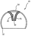
Figure 10 a to Figure 10 d as sectional view shown in the side view for the manufacture of the different step of the method flow of the cell-shell 49 of the reflection of light-emitting device.Replace cell-shell 31 and reflector 28 together with the combination of light-emitting device 27, for example can use cell-shell 49.Cell-shell 49 for example can be made by glass.
Figure 10 a is illustrated in the cell-shell 49 of the spherical shell section shape of first being processed, has at it opening 50 and lower limb 52 in (front portion) top 51, and this lower limb is shorter than semicircle (plane of the wideest diameter).
In first procedure of processing, can heat cell-shell 49 so that its distortion.
Figure 10 b illustrates second procedure of processing, and wherein, cell-shell 49 curves inwardly by be arranged on this instrument with the distortion of the form of punch die 53 in both sides in the zone at its top 51.Also can be with the structure punching press in cell-shell 49, for example as the honeycomb structure that characterizes reflector by punch die 53.
Figure 10 c illustrates ensuing procedure of processing, and wherein, cell-shell 49 is made to both sides minute surface in the zone at its top 51, exactly utilize reflecting layer 45, and for example metal layer is realized.
Protect by introducing covering pipe R zone cell-shell 49, that do not need to make minute surface.
How Figure 10 d illustrates will (enlarge) opening 50 betwixt by installing and fixing domes of for example being made by glass or cover 54 sealings.For example fix and to be undertaken by bonding or heating.
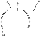
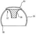
Figure 11 a to Figure 11 b is being used for the different step of cell-shell 55 with the method flow of reflector 56 combinations shown in the side view as sectional view.For example can use this combination 55,56 to replace cell-shell 31 and reflector 28 together with the combination of light-emitting device 27.Cell-shell 55 for example can be made by glass.
As shown in Figure 11 a, cell-shell 55 also is ball section shape or spherical shell section shape and has opening 57 in its (front portion) top 58 at this, and also has lower limb 59, and this lower limb is narrower than semicircle.
In this method, cell-shell 55 is distortion not, but as shown in Figure 11 b, in the opening 57 of from the outside reflector 56 being packed into.Preferably, reflector 56 is not crossed the edge that defines opening 57 at any point and is outwards protruded.Next, opening 57 seals by lid 61 with the reflector 56 of packing into therein.At this, cover 61 fixation reflex bodies 56.Advantageously, if reflector 56 only flexiblely hangs on 3 points and flatly slightly, this structure can tensioning under the situation of heating thus.
Cell-shell 55 and lid 61 are advantageously made by glass.
The light-emitting device of making minute surface at its cell-shell has the following advantages, it has high-quality impression, this be because, by making the mode of minute surface, even under the situation of having used adhesive, this lid only for example also appears to by glass with metal the same.
Figure 12 shown in the side view as reflector 60 minute surface and diffuse reflection.Reflector 60 has the alternately bar-shaped zone of level, i.e. areas of specular reflection 62 and diffuse reflection zone 63.
Figure 13 is in that another is as reflector 64 minute surface and diffuse reflection shown in the side view, and it has now and replaces vertical bar-shaped zone, i.e. areas of specular reflection 65 and diffuse reflection zone 66.
Distribute by the solid angle of using areas of specular reflection and diffuse reflection zone can adjust expectation more accurately.
Certainly the present invention not only is confined to the embodiment that illustrates.
Therefore, the reflector of bottom side also can use in other light-emitting device except using in according to the light-emitting device of second embodiment.
REFERENCE NUMBER LIST
1 light-emitting device
2 smooth generating units
3 substrates
The front of 4 substrates
The outer light-emitting zone of 5a
Light-emitting zone in the 5b
The back side of 6 substrates
7 cooling bodies
8 reflectors
The end of the back of 9 reflectors
The lateral surface of 10 reflectors
The edge of 11 reflectors
The medial surface of 12 reflectors
13 cell-shells
14 connectors
15 spot lights
16 smooth generating units
17 light-emitting zones
18 light-emitting devices
19 reflectors
20 circuit boards
The lower limb of 21 reflectors
22 latch
The 22a sleeve pipe
23 cooling bodies
24 recess
25 reflectors
26 screws
27 light-emitting devices
28 reflectors
The top edge of 29 reflectors
The medial surface of 30 cell-shells
31 cell-shells
32 positioning saliences
The opened end portions of 33 reflectors
34 light-emitting devices
35 reflectors
The bottom of 36 reflectors
The upper end of 37 reflectors
38 smooth generating units
39 electric leads
40 circuit boards
41 cable threading openings
42 light-emitting devices
43 cell-shells
The medial surface of 44 cell-shells
45 reflecting layer
46 adhesive
47 lids
48 fastening areas
49 cell-shells
50 openings
51 tops
The lower limb of 52 cell-shells
53 punch dies
54 lids
55 cell-shells
56 reflectors
57 openings
58 tops
The lower limb of 59 cell-shells
60 reflectors
61 lids
62 areas of specular reflection
63 scattered reflection zones
64 reflectors
65 areas of specular reflection
66 scattered reflection zones
The L longitudinal axis
The E light-emitting face
The S shadow region
The OH upper half-space
The UH lower half-space
The SB top area
R covers pipe
Claims (15)
1. light-emitting device (1; 18; 27; 34; 42), has at least one reflector (8; 19; 25; 28; 35; 56; 60; 64) and at least one light generating unit (2; 16; 38), wherein
-at least one described reflector (8; 19; 25; 28; 35; 56; 60; 64) arrange and layout is used for, with at least a portion by the light of at least one described smooth generating unit emission be reflected into can not the area of space (UH) by at least one described smooth generating unit direct irradiation in, and
-at least one described smooth generating unit (2; 16; 38) having at least one has at described light-emitting device (1; 18; 27; 34; 42) uniformly light-emitting zone (5a, the 5b of emission characteristics basically on the circumferencial direction; 17).
2. light-emitting device (1 according to claim 1; 18; 27; 34; 42), wherein, at least one described light-emitting zone (5a, 5b; 17) be designed to divide at least section ground rounded or ringwise.
3. according to each described light-emitting device (1 in the aforementioned claim; 18; 27; 34; 42), wherein, at least one described smooth generating unit (2; 16; 38) has at least one OLED.
4. according to each described light-emitting device (1) in the aforementioned claim, wherein, at least one described smooth generating unit (2; 16) have a plurality of, particularly arrange circlewise, with semiconductor light sources form, point-like (15) of semiconductor light source chips (15b).
5. according to each described light-emitting device (1 in the aforementioned claim; 18; 27; 34; 42), wherein, described reflector (8; 19; 25; 28; 35; 56; 60; 64) have and attach troops to a unit in lateral surface at least one described smooth generating unit, reflection, described lateral surface with respect to longitudinal axis be rotational symmetric and along with apart from the increase of the height of at least one described smooth generating unit at least branch's section ground with the increasing angles expansion with respect to described longitudinal axis.
6. light-emitting device (1 according to claim 5; 18; 27; 34; 42), wherein, described reflector (8; 19; 25; 28; 35; 56; 60; 64) be at least one described smooth generating unit (2 at least in part; 16; 38) form vault.
7. according to each described light-emitting device (1 in the aforementioned claim; 18; 27), wherein, described reflector (8; 19; 28) be designed to overlap tubular, have medial surface (12) and lateral surface (10) and be that both sides are opened wide and wherein, described medial surface (12) and described lateral surface (10) can both be by described smooth generating units (2; 16) irradiation.
8. light-emitting device (1 according to claim 7; 18; 27), wherein, described smooth generating unit (2) has at least two light-emitting zone (5a, 5b), wherein, described lateral surface (10) can shine by at least one described light-emitting zone (5a), and described medial surface (12) can be by another described light-emitting zone (5b) irradiation at least.
9. according to each described light-emitting device (1 in the aforementioned claim; 18; 34), wherein, described reflector (8; 19; 35) be installed in described smooth generating unit (2; 38) on.
10. according to each described light-emitting device (27 in the claim 1 to 9; 42), wherein, described reflector (28; 45; 56) be fixed on and be that at least one described smooth generating unit (16) forms cell-shell (31 vault, printing opacity; 43) on, and be arranged in the top of at least one described smooth generating unit (16) vacantly.
11. according to each described light-emitting device (42) in the claim 1 to 9, wherein, described light-emitting device (42) has and is that at least one described smooth generating unit (16) forms cell-shell (43 vault, printing opacity; 49) and described reflector (45) be integrated in the described cell-shell (43).
12. according in claim 10 or 11 each in conjunction with the described light-emitting device (27 of claim 7; 42), wherein, described smooth generating unit (16) has the just light-emitting zone (17) of what a circle.
13. according to each described light-emitting device (1 in the aforementioned claim; 18; 27; 34; 42), wherein, described light-emitting device (1; 18; 27; 34; 42) be remodeling lamp, particularly incandescent lamp-remodeling lamp.
14. the method for the manufacture of light-emitting device according to claim 12, wherein, described method has following steps at least:
-make top (51) at cell-shell locate to have opening (50), particularly described cell-shell (49) distortion like this of spheroid section shape, thereby described cell-shell curves inwardly in the zone at the described top (51) of described cell-shell;
-described cell-shell (49) is made minute surface at least in the zone at the described top (51) of described cell-shell;
-described opening (50) is sealed.
15. the method for the manufacture of light-emitting device according to claim 11, wherein, described method has following steps at least:
In-the cell-shell of spheroid section shape (55) of from the outside reflector (56) being packed into particularly, described cell-shell locates to have opening (57) at the top (58) of described cell-shell;
-utilize the described reflector (56) of packing into therein to seal described opening (57).
Applications Claiming Priority (3)
| Application Number | Priority Date | Filing Date | Title |
|---|---|---|---|
| DE102010043921.5A DE102010043921B4 (en) | 2010-11-15 | 2010-11-15 | Lighting device and method for producing a lighting device |
| DE102010043921.5 | 2010-11-15 | ||
| PCT/EP2011/069417 WO2012065860A1 (en) | 2010-11-15 | 2011-11-04 | Illumination device and method for producing an illumination device |
Publications (1)
| Publication Number | Publication Date |
|---|---|
| CN103210254A true CN103210254A (en) | 2013-07-17 |
Family
ID=44910211
Family Applications (1)
| Application Number | Title | Priority Date | Filing Date |
|---|---|---|---|
| CN2011800550260A Pending CN103210254A (en) | 2010-11-15 | 2011-11-04 | Light emitting device and method for manufacturing light emitting device |
Country Status (4)
| Country | Link |
|---|---|
| US (1) | US9273847B2 (en) |
| CN (1) | CN103210254A (en) |
| DE (1) | DE102010043921B4 (en) |
| WO (1) | WO2012065860A1 (en) |
Cited By (5)
| Publication number | Priority date | Publication date | Assignee | Title |
|---|---|---|---|---|
| WO2015135327A1 (en) * | 2014-03-12 | 2015-09-17 | 厦门萤火虫节能科技有限公司 | Full-direction illuminating standardized led bulb lamp |
| CN106051520A (en) * | 2016-07-19 | 2016-10-26 | 欧普照明股份有限公司 | Light source module and illuminating equipment |
| CN106090731A (en) * | 2016-07-26 | 2016-11-09 | 安徽华夏显示技术股份有限公司 | A kind of LED anticollision beacon light source |
| CN109311422A (en) * | 2016-06-16 | 2019-02-05 | 奈图恩解决方案有限公司 | Mobile emergency light unit |
| CN117046125A (en) * | 2022-09-07 | 2023-11-14 | 株式会社万代 | LED toys |
Families Citing this family (16)
| Publication number | Priority date | Publication date | Assignee | Title |
|---|---|---|---|---|
| DE202012100962U1 (en) * | 2012-03-19 | 2013-06-25 | Chiron-Werke Gmbh & Co. Kg | machine light |
| US9057503B2 (en) * | 2013-03-05 | 2015-06-16 | Terralux, Inc. | Light-emitting diode light bulb generating direct and decorative illumination |
| JP6125308B2 (en) * | 2013-04-24 | 2017-05-10 | 本田技研工業株式会社 | Vehicle taillight device |
| TW201508207A (en) * | 2013-08-27 | 2015-03-01 | Hon Hai Prec Ind Co Ltd | Vehicle lamp module |
| JP6206805B2 (en) * | 2013-10-03 | 2017-10-04 | パナソニックIpマネジメント株式会社 | Light emitting module, illumination light source, and illumination device |
| US20150184833A1 (en) * | 2013-12-27 | 2015-07-02 | Ming-Che Wu | Tungsten-Filament-Like Light-Emitting Diode Lamp Structure |
| JP6395033B2 (en) * | 2014-07-14 | 2018-09-26 | パナソニックIpマネジメント株式会社 | Lighting device |
| EP2980472B1 (en) * | 2014-07-28 | 2018-01-17 | OSRAM GmbH | A lighting device and corresponding method |
| US9279548B1 (en) * | 2014-08-18 | 2016-03-08 | 3M Innovative Properties Company | Light collimating assembly with dual horns |
| US9651219B2 (en) * | 2014-08-20 | 2017-05-16 | Elumigen Llc | Light bulb assembly having internal redirection element for improved directional light distribution |
| WO2017114429A1 (en) * | 2015-12-31 | 2017-07-06 | 欧普照明股份有限公司 | A led lighting device |
| US9995441B2 (en) * | 2016-02-08 | 2018-06-12 | Cree, Inc. | LED lamp with internal reflector |
| TWI614451B (en) * | 2017-06-13 | 2018-02-11 | 財團法人工業技術研究院 | Led lighting module and method of radiating light thereof |
| JP7125055B2 (en) * | 2018-07-30 | 2022-08-24 | 株式会社Smaco技術研究所 | LED lighting device |
| JP6823822B2 (en) * | 2018-10-31 | 2021-02-03 | 株式会社パトライト | Indicator light |
| JP2025042454A (en) * | 2023-09-14 | 2025-03-27 | 東芝ライテック株式会社 | Vehicle lighting device and vehicle lamp |
Citations (7)
| Publication number | Priority date | Publication date | Assignee | Title |
|---|---|---|---|---|
| CN1171514A (en) * | 1996-07-18 | 1998-01-28 | 株式会社小糸制作所 | Marker light for vehicle |
| FR2816693B1 (en) * | 2000-11-16 | 2003-06-13 | Regie Autonome Transports | PORTABLE LUMINOUS SIGNALING APPARATUS |
| US6679618B1 (en) * | 1997-10-17 | 2004-01-20 | Truck Lite Co., Inc. | Light emitting diode 360 degree warning lamp |
| CN2618045Y (en) * | 2003-03-10 | 2004-05-26 | 许顺喜 | LED lamp bulb |
| EP1574779B1 (en) * | 2004-03-10 | 2008-11-05 | odelo GmbH | Reflex reflector for tail-lights of vehicles |
| WO2008146229A2 (en) * | 2007-05-29 | 2008-12-04 | Koninklijke Philips Electronics N.V. | Illumination system, luminaire and backlighting unit |
| WO2010128438A1 (en) * | 2009-05-07 | 2010-11-11 | Koninklijke Philips Electronics N.V. | Lighting device with phosphor and dichroic filter |
Family Cites Families (21)
| Publication number | Priority date | Publication date | Assignee | Title |
|---|---|---|---|---|
| US6149283A (en) * | 1998-12-09 | 2000-11-21 | Rensselaer Polytechnic Institute (Rpi) | LED lamp with reflector and multicolor adjuster |
| US8360615B2 (en) * | 2000-05-08 | 2013-01-29 | Farlight, Llc | LED light module for omnidirectional luminaire |
| US6932496B2 (en) * | 2002-04-16 | 2005-08-23 | Farlight Llc | LED-based elevated omnidirectional airfield light |
| AU2003298561A1 (en) * | 2002-08-23 | 2004-05-13 | Jonathan S. Dahm | Method and apparatus for using light emitting diodes |
| US7114834B2 (en) * | 2002-09-23 | 2006-10-03 | Matrix Railway Corporation | LED lighting apparatus |
| DE20311169U1 (en) * | 2003-07-21 | 2003-10-09 | Hella KG Hueck & Co., 59557 Lippstadt | Signal lamp with LED panel, light emitting diode (LED) set, whose light is reflected by fixed reflector to LED panel |
| DE102004025473A1 (en) * | 2003-11-20 | 2005-06-23 | Werma Signaltechnik Gmbh + Co. Kg | Signal appliance e.g. for displaying operating state in machine and equipment, has reflector with reflection surface have continuous curvature |
| US7645053B2 (en) * | 2005-01-13 | 2010-01-12 | Honeywell International Inc. | Rotationally symmetrical LED-based anti-collision light for aircraft |
| US7347586B2 (en) * | 2005-05-09 | 2008-03-25 | Gamasonic Ltd. | LED light bulb |
| US7572030B2 (en) * | 2005-06-22 | 2009-08-11 | Carmanah Technologies Corp. | Reflector based optical design |
| ITRE20060052A1 (en) * | 2006-04-28 | 2007-10-29 | Incerti Simonini Snc | SECONDARY OPTICAL DEVICE FOR LEDS LAMPS |
| WO2007130536A2 (en) * | 2006-05-05 | 2007-11-15 | Cree Led Lighting Solutions, Inc. | Lighting device |
| DE102006056700B4 (en) * | 2006-11-30 | 2011-04-07 | Hnc Import-Export & Vertriebs Ag | Campingleuchte |
| DE102007056874A1 (en) | 2007-11-26 | 2009-05-28 | Osram Gesellschaft mit beschränkter Haftung | LED lighting device with conversion reflector |
| WO2009103246A1 (en) * | 2008-02-22 | 2009-08-27 | Tri-Concept Technology Limited | Led obstruction light |
| CN100595479C (en) * | 2008-05-12 | 2010-03-24 | 深圳市众明半导体照明有限公司 | A LED light bulb with light on the back |
| US8529102B2 (en) * | 2009-04-06 | 2013-09-10 | Cree, Inc. | Reflector system for lighting device |
| US8596825B2 (en) * | 2009-08-04 | 2013-12-03 | 3M Innovative Properties Company | Solid state light with optical guide and integrated thermal guide |
| DE102009048313A1 (en) | 2009-10-05 | 2011-04-07 | Osram Gesellschaft mit beschränkter Haftung | Lighting device and method for mounting a lighting device |
| US7909481B1 (en) * | 2009-10-06 | 2011-03-22 | IMG Lighting, Inc. | LED lighting device having improved cooling characteristics |
| US20120262915A1 (en) * | 2011-04-18 | 2012-10-18 | Jade Yang Co., Ltd. | Led (light-emitting diode) lamp with light reflection |
-
2010
- 2010-11-15 DE DE102010043921.5A patent/DE102010043921B4/en not_active Expired - Fee Related
-
2011
- 2011-11-04 CN CN2011800550260A patent/CN103210254A/en active Pending
- 2011-11-04 US US13/885,166 patent/US9273847B2/en not_active Expired - Fee Related
- 2011-11-04 WO PCT/EP2011/069417 patent/WO2012065860A1/en not_active Ceased
Patent Citations (7)
| Publication number | Priority date | Publication date | Assignee | Title |
|---|---|---|---|---|
| CN1171514A (en) * | 1996-07-18 | 1998-01-28 | 株式会社小糸制作所 | Marker light for vehicle |
| US6679618B1 (en) * | 1997-10-17 | 2004-01-20 | Truck Lite Co., Inc. | Light emitting diode 360 degree warning lamp |
| FR2816693B1 (en) * | 2000-11-16 | 2003-06-13 | Regie Autonome Transports | PORTABLE LUMINOUS SIGNALING APPARATUS |
| CN2618045Y (en) * | 2003-03-10 | 2004-05-26 | 许顺喜 | LED lamp bulb |
| EP1574779B1 (en) * | 2004-03-10 | 2008-11-05 | odelo GmbH | Reflex reflector for tail-lights of vehicles |
| WO2008146229A2 (en) * | 2007-05-29 | 2008-12-04 | Koninklijke Philips Electronics N.V. | Illumination system, luminaire and backlighting unit |
| WO2010128438A1 (en) * | 2009-05-07 | 2010-11-11 | Koninklijke Philips Electronics N.V. | Lighting device with phosphor and dichroic filter |
Cited By (5)
| Publication number | Priority date | Publication date | Assignee | Title |
|---|---|---|---|---|
| WO2015135327A1 (en) * | 2014-03-12 | 2015-09-17 | 厦门萤火虫节能科技有限公司 | Full-direction illuminating standardized led bulb lamp |
| CN109311422A (en) * | 2016-06-16 | 2019-02-05 | 奈图恩解决方案有限公司 | Mobile emergency light unit |
| CN106051520A (en) * | 2016-07-19 | 2016-10-26 | 欧普照明股份有限公司 | Light source module and illuminating equipment |
| CN106090731A (en) * | 2016-07-26 | 2016-11-09 | 安徽华夏显示技术股份有限公司 | A kind of LED anticollision beacon light source |
| CN117046125A (en) * | 2022-09-07 | 2023-11-14 | 株式会社万代 | LED toys |
Also Published As
| Publication number | Publication date |
|---|---|
| WO2012065860A1 (en) | 2012-05-24 |
| US20130235582A1 (en) | 2013-09-12 |
| DE102010043921A1 (en) | 2012-05-16 |
| DE102010043921B4 (en) | 2016-10-06 |
| US9273847B2 (en) | 2016-03-01 |
Similar Documents
| Publication | Publication Date | Title |
|---|---|---|
| CN103210254A (en) | Light emitting device and method for manufacturing light emitting device | |
| US8967829B2 (en) | Illumination device employing LEDS that has equivalent light distribution characteristics of incandescent lamps | |
| US8253316B2 (en) | Dimmable LED lamp | |
| US6803607B1 (en) | Surface mountable light emitting device | |
| WO2012124637A1 (en) | Illumination device | |
| CN102159876A (en) | Color mixing method for consistent color quality | |
| AU2016204281B2 (en) | Optical system and lighting device comprised thereof | |
| US12007079B2 (en) | Backlit lamp having directional light source | |
| CN102788282A (en) | A LED light tube with light type modulation | |
| US9739426B2 (en) | Bulb for semiconductor luminous device, and semiconductor luminous device | |
| US8764231B2 (en) | Light-emitting diode light source | |
| JP2008218184A (en) | Light source unit | |
| CN103234129A (en) | Light emitting diode (LED) bulb | |
| RU2617030C2 (en) | Light source, lamp and method of making light source | |
| CN110440169A (en) | A kind of lens, lens group and lamps and lanterns | |
| TWI391602B (en) | Lamp | |
| JP2012226922A (en) | Led light emitting device | |
| JP2007318176A (en) | Light emitting diode | |
| KR102249908B1 (en) | Slim type led flood light | |
| TWM552229U (en) | Auxiliary illumination lamp for vehicle | |
| CN207196380U (en) | A kind of automobile long-and-short distant light based on LASER Light Source |
Legal Events
| Date | Code | Title | Description |
|---|---|---|---|
| C06 | Publication | ||
| PB01 | Publication | ||
| C10 | Entry into substantive examination | ||
| SE01 | Entry into force of request for substantive examination | ||
| C02 | Deemed withdrawal of patent application after publication (patent law 2001) | ||
| WD01 | Invention patent application deemed withdrawn after publication |
Application publication date: 20130717 |