Description of drawings
Fig. 1 illustrates the schematic diagram into a kind of Automatic Guided Vehicle guidance system;
Fig. 2 illustrates the schematic top plan view into a kind of rail-free district;
Fig. 3 illustrates the process flow diagram into a kind of Automatic Guided Vehicle guidance method;
Fig. 4 illustrates and carries out the schematic diagram of shortest path planning for arithmetic element according to minimum cut-in angle;
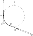
Fig. 5 illustrates as arithmetic element according to rail end point and the circular schematic diagram that carries out path planning;
Fig. 6 illustrates as arithmetic element according to rail end point and the oval schematic diagram that carries out path planning;
Fig. 7 illustrates the schematic diagram that is arranged at workstation for wireless radio frequency identification mark is adjacent.
Wherein, Reference numeral
1: the Automatic Guided Vehicle guidance system
5: circle
6: ellipse
11: rail system
12a, 12b: Automatic Guided Vehicle
11a ', 11b ', 11c ', 11d ', 11e ', 11f ', 11g ': wireless radio frequency identification mark
12a ', 12b ': diagram label
13: image capturing device
14: arithmetic element
15: operation and control interface
16: the rail-free district
17e, 17f, 17g: workstation
18a, 18b: wireless radio frequency identification mark reading device
19a, 19b: wireless communication module
21~23: step
AA ', BB ', CC ', DD ': track branch
A ', B ', C ', D ': rail end point
B ': point of contact
H: joining
L1, L2, L3, L4: straight line
O ': the oval center of circle
θ (t): angle information
θ min: minimum cut-in angle
θ 1: towards the angle
Embodiment
Below in conjunction with accompanying drawing, structural principle of the present invention and principle of work are done concrete description:
Please be simultaneously with reference to Fig. 1, Fig. 2 and Fig. 3, Fig. 1 illustrates the schematic diagram into a kind of Automatic Guided Vehicle guidance system, and Fig. 2 illustrates the schematic top plan view into a kind of rail-free district, and Fig. 3 illustrates the process flow diagram into a kind of Automatic Guided Vehicle guidance method.Automatic Guided Vehicle guidance system 1 comprises rail system 11, Automatic Guided Vehicle 12a, image capturing device 13, arithmetic element 14 and operation and control interface 15.Rail system 11 guidance automatic transporting equipment 12a, Automatic Guided Vehicle 12a are applicable to be guided on rail system 11 and mobile and de-orbit system 11 and 16 move in the rail-free district.Image capturing device 13 acquisition rail-free district coherent video.Rail-free district coherent video comprises the image in rail-free district 16 at least, and in addition, rail-free district coherent video also can further comprise the part track adjacent with rail-free district 16 or the image of end points.Operation and control interface 15 is to set work scheduling or the destination locations of Automatic Guided Vehicle 12a through arithmetic element 14.Arithmetic element 14 computing Automatic Guided Vehicle 12a are 16 positional information in the rail-free district.The Automatic Guided Vehicle guidance method can be applied to Automatic Guided Vehicle guidance system 1 and comprise the steps:
At first as shown in step 21, arithmetic element 14 judges the Automatic Guided Vehicle 12a system 11 that whether de-orbits.When Automatic Guided Vehicle 12a did not de-orbit system 11, execution in step 22.As shown in step 22, by rail system 11 guidance automatic transporting equipment 12a.On the contrary, when Automatic Guided Vehicle 12a broke away from this rail system, execution in step 23.As shown in step 23, by arithmetic element 14 according to rail-free district coherent video guidance automatic transporting equipment 12a.
Although above stated specification illustrates as an example of Automatic Guided Vehicle 12a example, so embodiment is not limited to this, and the Automatic Guided Vehicle number is adjusted in visual practical application.For instance, Automatic Guided Vehicle guidance system 1 can also comprise Automatic Guided Vehicle 12b, and the guide mode of Automatic Guided Vehicle 12b can be as Automatic Guided Vehicle 12a.What need to specify is, when Automatic Guided Vehicle 12a and Automatic Guided Vehicle 12b de-orbit after system 11 enters rail-free district 16, is to change by arithmetic element 14 according to rail-free district coherent video guidance automatic transporting equipment 12a and Automatic Guided Vehicle 12b.Arithmetic element 14 can suitably be carried out Automatic Guided Vehicle 12a and Automatic Guided Vehicle 12b according to rail-free district coherent video, and 16 path planning bumps to prevent Automatic Guided Vehicle 12a and Automatic Guided Vehicle 12b in the rail-free district.
Referring again to Fig. 1, Automatic Guided Vehicle guidance system 1 can comprise diagram label 12a ' and diagram label 12b ' at least, and diagram label 12a ' and diagram label 12b ' are arranged at respectively Automatic Guided Vehicle 12a and Automatic Guided Vehicle 12b.Arithmetic element is according to status and the positional information of diagram label 12a ' and diagram label 12b ' identification Automatic Guided Vehicle 12a and Automatic Guided Vehicle 12b.So embodiment is not limited to this, and arithmetic element 14 also can be identified Automatic Guided Vehicle 12a and Automatic Guided Vehicle 12b according to rail-free district's coherent video and image recognition technology.
Referring again to Fig. 1, furthermore, rail system 11 comprises the track AA ' of branch, the track BB ' of branch, the track CC ' of branch and the track DD ' of branch.The AA ' of track branch, the track BB ' of branch, the track CC ' of branch and the track DD ' of branch comprise respectively rail end point A ', rail end point B ', rail end point C ' and rail end point D '.When Automatic Guided Vehicle 12a is rail end point B ' by the destination locations that rail end point A ' enters rail-free district 16 and Automatic Guided Vehicle 12a.Arithmetic element 14 according to rail-free district's coherent video and destination locations carry out Automatic Guided Vehicle 12a in the rail-free district 16 path planning and contrast locating to until Automatic Guided Vehicle arrives rail end point B ' by rail end point A '.
Please more simultaneously with reference to Fig. 1 and Fig. 2, Automatic Guided Vehicle guidance system 1 can also comprise radio frequency identification (Radio Frequency Identification, RFID) label 11a ', wireless radio frequency identification mark 11b ', wireless radio frequency identification mark 11c ' and wireless radio frequency identification mark 11d ', wireless radio frequency identification mark reading device 18a, wireless radio frequency identification mark reading device 18b, wireless communication module 19a and wireless communication module 19b.Wireless communication module 19a and wireless communication module 19b are arranged at respectively Automatic Guided Vehicle 12a and Automatic Guided Vehicle 12b, and Automatic Guided Vehicle 12a and Automatic Guided Vehicle 12b transmit signal to arithmetic element 14 through wireless communication module 19a and wireless communication module 19b respectively.Wireless radio frequency identification mark reading device 18a and wireless radio frequency identification mark reading device 18b are arranged at respectively Automatic Guided Vehicle 12a and Automatic Guided Vehicle 12b, and wireless radio frequency identification mark reading device 18a and wireless radio frequency identification mark reading device 18b read wireless radio frequency identification mark 11a ', wireless radio frequency identification mark 11b ', wireless radio frequency identification mark 11c ' or wireless radio frequency identification mark 11d ' with the triggering as arithmetic element 14 guidance automatic transporting equipment 12a and Automatic Guided Vehicle 12b mechanism.Wireless radio frequency identification mark 11a ', wireless radio frequency identification mark 11b ', wireless radio frequency identification mark 11c ' and wireless radio frequency identification mark 11d ' are arranged at respectively rail end point A ', rail end point B ', rail end point C ' and rail end point D '.
In the process of rail system 11 guidance automatic transporting equipment 12a, when if the wireless radio frequency identification mark reading device 18a of Automatic Guided Vehicle 12a reads arbitrary wireless radio frequency identification mark 11a ', wireless radio frequency identification mark 11b ', wireless radio frequency identification mark 11c ' or wireless radio frequency identification mark 11d ', Automatic Guided Vehicle 12a will transmit signal by wireless communication module 19a give arithmetic element 14, and arithmetic element 14 judges the Automatic Guided Vehicle 12a system 11 that whether de-orbits.This action is for being about to the signal notice of the system of de-orbiting, and starts simultaneously arithmetic element 14 and carry out rail-free district coherent video guided mode.When arithmetic element 14 was carried out rail-free district coherent video guided mode, Automatic Guided Vehicle 12a was no longer by rail system 11 guidings.
On the contrary, in the process of arithmetic element 14 according to rail-free district coherent video guidance automatic transporting equipment 12a, if the wireless radio frequency identification mark reading device 18a of Automatic Guided Vehicle 12a read wireless radio frequency identification mark 11a ', wireless radio frequency identification mark 11b ', wireless radio frequency identification mark 11c ' or wireless radio frequency identification mark 11d ' one of them the time, Automatic Guided Vehicle 12a will transmit signal by wireless communication module 19a give arithmetic element 14.This action is the signal notice of soon injection system, and changes simultaneously by rail system 11 guidance automatic transporting equipment 12a.
Similarly, in the process of rail system 11 guidance automatic transporting equipment 12b, if the wireless radio frequency identification mark reading device 18b of Automatic Guided Vehicle 12b read wireless radio frequency identification mark 11a ', wireless radio frequency identification mark 11b ', wireless radio frequency identification mark 11c ' or wireless radio frequency identification mark 11d ' one of them the time, Automatic Guided Vehicle 12a will transmit signal by wireless communication module 19b give arithmetic element 14, and arithmetic element 14 judges the Automatic Guided Vehicle 12a system 11 that whether de-orbits.This action is for being about to the signal notice of the system of de-orbiting, and starts simultaneously arithmetic element 14 and carry out rail-free district coherent video guided mode.When arithmetic element 14 was carried out rail-free district coherent video guided mode, Automatic Guided Vehicle 12b was no longer by rail system 11 guidings.
On the contrary, in the process of arithmetic element 14 according to rail-free district coherent video guidance automatic transporting equipment 12b, if the wireless radio frequency identification mark reading device 18b of Automatic Guided Vehicle 12b read wireless radio frequency identification mark 11a ', wireless radio frequency identification mark 11b ', wireless radio frequency identification mark 11c ' or wireless radio frequency identification mark 11d ' one of them the time, Automatic Guided Vehicle 12b will transmit signal by wireless communication module 19b give arithmetic element 14.This action is the signal notice of soon injection system, and changes simultaneously by rail system 11 guidance automatic transporting equipment 12b.
The mode that above-mentioned Automatic Guided Vehicle 12a triggers the system 11 that de-orbits is not limited to the technology of utilizing wireless radio frequency identification mark.For instance, can adopt the identification labels such as photoelectricity proximity switch, magnetic inductive, mechanical trigger-type.Arithmetic element 14 can the image application identification techniques judges the Automatic Guided Vehicle 12a system 11 that whether de-orbits in addition.In one embodiment, rail-free district coherent video only comprises the image in rail-free district 16, and does not comprise the image of the part track adjacent with rail-free district 16; When rail-free district coherent video showed Automatic Guided Vehicle 12a, arithmetic element 14 picked out Automatic Guided Vehicle 12a and enters the rail-free district and namely judge the Automatic Guided Vehicle 12a system 11 that de-orbits.
16 path planning can have multiple different implementation to Automatic Guided Vehicle 12a in the rail-free district, follow-uply will give a few examples explanation.For instance, when Automatic Guided Vehicle 12a be rail end point B ' by the destination locations that rail end point A ' enters rail-free district 16 and Automatic Guided Vehicle 12a.Arithmetic element 14 is calculated the relative position information of Automatic Guided Vehicle 12a and rail end point B ' according to rail-free district coherent video vision, and calculates the angle information θ (t) of Automatic Guided Vehicle 12a ' and the track BB ' of branch according to rail-free district coherent video vision.Arithmetic element 14 is carried out path planning according to relative position information and angle information θ (t).Because image capturing device 13 can capture rail-free district coherent video vision continuously, so arithmetic element 14 can revise relative position information and angle information θ (t) in real time, to carry out suitable path planning.
Please be simultaneously with reference to Fig. 1, Fig. 3 and Fig. 4, Fig. 4 illustrates and carries out the schematic diagram of shortest path planning for arithmetic element according to minimum cut-in angle.Arithmetic element 14 is except utilizing relative position information and angle information θ (t) to carry out path planning, arithmetic element 14 also can carry out according to the minimum cut-in angle θ min of the track BB ' of branch Automatic Guided Vehicle 12a in the rail-free district 16 shortest path planning.The derailing that meets accident during for fear of the Automatic Guided Vehicle 12a injection BB ' of branch, Automatic Guided Vehicle 12a can be with the angle injection BB ' of branch less than minimum cut-in angle θ min when the injection BB ' of branch.Minimum cut-in angle θ min looks the ability of Automatic Guided Vehicle 12a and different, and is to advance towards the direction of angle θ 1 when the Automatic Guided Vehicle 12a deorbit BB ' of branch.Arithmetic element 14 is found out straight line L1 according to minimum cut-in angle θ min, and finds out according to rail end point A ' and towards angle θ 1 the straight line L2 that intersects with straight line L1.Arithmetic element 14 is carried out Automatic Guided Vehicle 12a by the shortest path planning of rail end point A ' to rail end point B ' according to straight line L1 and straight line L2.
Please be simultaneously with reference to Fig. 1, Fig. 3 and Fig. 5, Fig. 5 illustrates as arithmetic element according to rail end point and the circular schematic diagram that carries out path planning.Arithmetic element 14 is except utilizing minimum cut-in angle θ min to carry out path planning, and arithmetic element 14 also can be carried out path planning according to rail end point A ', rail end point B ' and circular 5.Arithmetic element 14 is calculated the joining H of the track AA ' of branch and the track BB ' of branch bearing of trend.The line that the line of rail end point A ' and joining H is defined as line segment A ' H and rail end point B ' and joining H is defined as line segment B ' H.Arithmetic element 14 is selected shorter one among line segment A ' H and line segment B ' H, and take shorter one's entity rail end point as a point of contact.Take rail end point A ' as the process point in Fig. 5 illustrates.Arithmetic element is according to finding circular 5 to be tangential on the track AA ' of branch and the track BB ' of branch bearing of trend through point, arithmetic element 14 according to rail end point A ', rail end point B ', point of contact b ' and circular 5 carry out Automatic Guided Vehicle 12a in the rail-free district 16 path planning.Arithmetic element 14 is found out point of contact b ' and is tangential on line segment B ' H.Automatic Guided Vehicle 12a lies in the Automatic Guided Vehicle 12a terminal A that de-orbits in the path planning in rail-free district 16 ' after advance to point of contact b ' along circular 5 circumference, follow-up again along the straight line bearing of trend straight ahead of the track BB ' of branch to rail end point B '.Automatic Guided Vehicle 12a injection terminal B ' after, change by rail system 11 guidings.
Please be simultaneously with reference to Fig. 1, Fig. 3 and Fig. 6, Fig. 6 illustrates as arithmetic element according to rail end point and the oval schematic diagram that carries out path planning.Arithmetic element 14 is except utilizing rail end point A ', rail end point B ' and circular 5 to carry out path planning, and arithmetic element 14 also can be carried out path planning according to rail end point A ', rail end point B ' and oval 6.Arithmetic element 14 is calculated the joining H of the track AA ' of branch and the track BB ' of branch bearing of trend.The line that the line of rail end point A ' and joining H is defined as line segment A ' H and rail end point B ' and joining H is defined as line segment B ' H.Arithmetic element 14 is found out the parallel orbit BB ' of branch and through the straight line L3 of rail end point A ', and finds out perpendicular to straight line L3 and through the straight line L4 of rail end point B ', and straight line L3 and straight line L4 intersect at oval center of circle O '.In the present embodiment, line segment B ' H be line segment A ' H and line segment B ' H in than the elder.Arithmetic element 14 is found out ellipse 6 take rail end point A ' to oval center of circle O ' and rail end point B ' to oval center of circle O ' for oval radius.Arithmetic element 14 according to rail end point A ', rail end point B ' and oval 6 carry out Automatic Guided Vehicle 12a in the rail-free district 16 path planning.After Automatic Guided Vehicle 12a lies in the Automatic Guided Vehicle 12a terminal A that de-orbits in the path planning in rail-free district 16 ' then advance to rail end point B ', follow-up Automatic Guided Vehicle 12a injection terminal B along oval 6 circumference ', change by rail system 11 guidings.
Please refer to Fig. 1, Fig. 3 and Fig. 7, Fig. 7 illustrates the schematic diagram that is arranged at workstation for wireless radio frequency identification mark is adjacent.Aforementioned Automatic Guided Vehicle guidance system 1 can also comprise wireless radio frequency identification mark 11e ', wireless radio frequency identification mark 11f ' and wireless radio frequency identification mark 11g '.Wireless radio frequency identification mark 11e ', wireless radio frequency identification mark 11f ' and wireless radio frequency identification mark 11g ' are adjacent workstation 17e, workstation 17f and the workstation 17g of being arranged at respectively.Arithmetic element 14 sequentially arrives rail end point B ' according to rail-free district's coherent video and wireless radio frequency identification mark 11e ', wireless radio frequency identification mark 11f ' and wireless radio frequency identification mark 11g ' guiding Automatic Guided Vehicle 12a by rail end point A ' after workstation 17e, workstation 17f and workstation 17g.
Certainly; the present invention also can have other various embodiments; in the situation that do not deviate from spirit of the present invention and essence thereof; those of ordinary skill in the art work as can make according to the present invention various corresponding changes and distortion, but these corresponding changes and distortion all should belong to the protection domain of the appended claim of the present invention.