CN103154474A - Gaseous-fuelled stoichiometric compression ignition internal combustion engine - Google Patents
Gaseous-fuelled stoichiometric compression ignition internal combustion engine Download PDFInfo
- Publication number
- CN103154474A CN103154474A CN2011800492570A CN201180049257A CN103154474A CN 103154474 A CN103154474 A CN 103154474A CN 2011800492570 A CN2011800492570 A CN 2011800492570A CN 201180049257 A CN201180049257 A CN 201180049257A CN 103154474 A CN103154474 A CN 103154474A
- Authority
- CN
- China
- Prior art keywords
- fuel
- engine
- intake valve
- firing chamber
- amount
- Prior art date
- Legal status (The legal status is an assumption and is not a legal conclusion. Google has not performed a legal analysis and makes no representation as to the accuracy of the status listed.)
- Granted
Links
Images



Classifications
-
- B—PERFORMING OPERATIONS; TRANSPORTING
- B60—VEHICLES IN GENERAL
- B60T—VEHICLE BRAKE CONTROL SYSTEMS OR PARTS THEREOF; BRAKE CONTROL SYSTEMS OR PARTS THEREOF, IN GENERAL; ARRANGEMENT OF BRAKING ELEMENTS ON VEHICLES IN GENERAL; PORTABLE DEVICES FOR PREVENTING UNWANTED MOVEMENT OF VEHICLES; VEHICLE MODIFICATIONS TO FACILITATE COOLING OF BRAKES
- B60T7/00—Brake-action initiating means
- B60T7/12—Brake-action initiating means for automatic initiation; for initiation not subject to will of driver or passenger
- B60T7/20—Brake-action initiating means for automatic initiation; for initiation not subject to will of driver or passenger specially for trailers, e.g. in case of uncoupling of or overrunning by trailer
-
- B—PERFORMING OPERATIONS; TRANSPORTING
- B60—VEHICLES IN GENERAL
- B60T—VEHICLE BRAKE CONTROL SYSTEMS OR PARTS THEREOF; BRAKE CONTROL SYSTEMS OR PARTS THEREOF, IN GENERAL; ARRANGEMENT OF BRAKING ELEMENTS ON VEHICLES IN GENERAL; PORTABLE DEVICES FOR PREVENTING UNWANTED MOVEMENT OF VEHICLES; VEHICLE MODIFICATIONS TO FACILITATE COOLING OF BRAKES
- B60T1/00—Arrangements of braking elements, i.e. of those parts where braking effect occurs specially for vehicles
- B60T1/02—Arrangements of braking elements, i.e. of those parts where braking effect occurs specially for vehicles acting by retarding wheels
- B60T1/06—Arrangements of braking elements, i.e. of those parts where braking effect occurs specially for vehicles acting by retarding wheels acting otherwise than on tread, e.g. employing rim, drum, disc, or transmission or on double wheels
-
- B—PERFORMING OPERATIONS; TRANSPORTING
- B62—LAND VEHICLES FOR TRAVELLING OTHERWISE THAN ON RAILS
- B62D—MOTOR VEHICLES; TRAILERS
- B62D63/00—Motor vehicles or trailers not otherwise provided for
- B62D63/06—Trailers
- B62D63/08—Component parts or accessories
-
- F—MECHANICAL ENGINEERING; LIGHTING; HEATING; WEAPONS; BLASTING
- F01—MACHINES OR ENGINES IN GENERAL; ENGINE PLANTS IN GENERAL; STEAM ENGINES
- F01N—GAS-FLOW SILENCERS OR EXHAUST APPARATUS FOR MACHINES OR ENGINES IN GENERAL; GAS-FLOW SILENCERS OR EXHAUST APPARATUS FOR INTERNAL-COMBUSTION ENGINES
- F01N3/00—Exhaust or silencing apparatus having means for purifying, rendering innocuous, or otherwise treating exhaust
- F01N3/08—Exhaust or silencing apparatus having means for purifying, rendering innocuous, or otherwise treating exhaust for rendering innocuous
- F01N3/10—Exhaust or silencing apparatus having means for purifying, rendering innocuous, or otherwise treating exhaust for rendering innocuous by thermal or catalytic conversion of noxious components of exhaust
- F01N3/101—Three-way catalysts
-
- F—MECHANICAL ENGINEERING; LIGHTING; HEATING; WEAPONS; BLASTING
- F02—COMBUSTION ENGINES; HOT-GAS OR COMBUSTION-PRODUCT ENGINE PLANTS
- F02B—INTERNAL-COMBUSTION PISTON ENGINES; COMBUSTION ENGINES IN GENERAL
- F02B43/00—Engines characterised by operating on gaseous fuels; Plants including such engines
- F02B43/10—Engines or plants characterised by use of other specific gases, e.g. acetylene, oxyhydrogen
-
- F—MECHANICAL ENGINEERING; LIGHTING; HEATING; WEAPONS; BLASTING
- F02—COMBUSTION ENGINES; HOT-GAS OR COMBUSTION-PRODUCT ENGINE PLANTS
- F02B—INTERNAL-COMBUSTION PISTON ENGINES; COMBUSTION ENGINES IN GENERAL
- F02B7/00—Engines characterised by the fuel-air charge being ignited by compression ignition of an additional fuel
- F02B7/06—Engines characterised by the fuel-air charge being ignited by compression ignition of an additional fuel the fuel in the charge being gaseous
-
- F—MECHANICAL ENGINEERING; LIGHTING; HEATING; WEAPONS; BLASTING
- F02—COMBUSTION ENGINES; HOT-GAS OR COMBUSTION-PRODUCT ENGINE PLANTS
- F02B—INTERNAL-COMBUSTION PISTON ENGINES; COMBUSTION ENGINES IN GENERAL
- F02B7/00—Engines characterised by the fuel-air charge being ignited by compression ignition of an additional fuel
- F02B7/06—Engines characterised by the fuel-air charge being ignited by compression ignition of an additional fuel the fuel in the charge being gaseous
- F02B7/08—Methods of operating
-
- F—MECHANICAL ENGINEERING; LIGHTING; HEATING; WEAPONS; BLASTING
- F02—COMBUSTION ENGINES; HOT-GAS OR COMBUSTION-PRODUCT ENGINE PLANTS
- F02D—CONTROLLING COMBUSTION ENGINES
- F02D19/00—Controlling engines characterised by their use of non-liquid fuels, pluralities of fuels, or non-fuel substances added to the combustible mixtures
- F02D19/06—Controlling engines characterised by their use of non-liquid fuels, pluralities of fuels, or non-fuel substances added to the combustible mixtures peculiar to engines working with pluralities of fuels, e.g. alternatively with light and heavy fuel oil, other than engines indifferent to the fuel consumed
- F02D19/08—Controlling engines characterised by their use of non-liquid fuels, pluralities of fuels, or non-fuel substances added to the combustible mixtures peculiar to engines working with pluralities of fuels, e.g. alternatively with light and heavy fuel oil, other than engines indifferent to the fuel consumed simultaneously using pluralities of fuels
- F02D19/10—Controlling engines characterised by their use of non-liquid fuels, pluralities of fuels, or non-fuel substances added to the combustible mixtures peculiar to engines working with pluralities of fuels, e.g. alternatively with light and heavy fuel oil, other than engines indifferent to the fuel consumed simultaneously using pluralities of fuels peculiar to compression-ignition engines in which the main fuel is gaseous
-
- F—MECHANICAL ENGINEERING; LIGHTING; HEATING; WEAPONS; BLASTING
- F02—COMBUSTION ENGINES; HOT-GAS OR COMBUSTION-PRODUCT ENGINE PLANTS
- F02D—CONTROLLING COMBUSTION ENGINES
- F02D41/00—Electrical control of supply of combustible mixture or its constituents
- F02D41/0025—Controlling engines characterised by use of non-liquid fuels, pluralities of fuels, or non-fuel substances added to the combustible mixtures
-
- F—MECHANICAL ENGINEERING; LIGHTING; HEATING; WEAPONS; BLASTING
- F02—COMBUSTION ENGINES; HOT-GAS OR COMBUSTION-PRODUCT ENGINE PLANTS
- F02D—CONTROLLING COMBUSTION ENGINES
- F02D41/00—Electrical control of supply of combustible mixture or its constituents
- F02D41/30—Controlling fuel injection
-
- F—MECHANICAL ENGINEERING; LIGHTING; HEATING; WEAPONS; BLASTING
- F02—COMBUSTION ENGINES; HOT-GAS OR COMBUSTION-PRODUCT ENGINE PLANTS
- F02D—CONTROLLING COMBUSTION ENGINES
- F02D41/00—Electrical control of supply of combustible mixture or its constituents
- F02D41/30—Controlling fuel injection
- F02D41/3011—Controlling fuel injection according to or using specific or several modes of combustion
- F02D41/3017—Controlling fuel injection according to or using specific or several modes of combustion characterised by the mode(s) being used
- F02D41/3035—Controlling fuel injection according to or using specific or several modes of combustion characterised by the mode(s) being used a mode being the premixed charge compression-ignition mode
- F02D41/3041—Controlling fuel injection according to or using specific or several modes of combustion characterised by the mode(s) being used a mode being the premixed charge compression-ignition mode with means for triggering compression ignition, e.g. spark plug
- F02D41/3047—Controlling fuel injection according to or using specific or several modes of combustion characterised by the mode(s) being used a mode being the premixed charge compression-ignition mode with means for triggering compression ignition, e.g. spark plug said means being a secondary injection of fuel
-
- F—MECHANICAL ENGINEERING; LIGHTING; HEATING; WEAPONS; BLASTING
- F02—COMBUSTION ENGINES; HOT-GAS OR COMBUSTION-PRODUCT ENGINE PLANTS
- F02D—CONTROLLING COMBUSTION ENGINES
- F02D41/00—Electrical control of supply of combustible mixture or its constituents
- F02D41/30—Controlling fuel injection
- F02D41/38—Controlling fuel injection of the high pressure type
- F02D41/40—Controlling fuel injection of the high pressure type with means for controlling injection timing or duration
- F02D41/402—Multiple injections
-
- F—MECHANICAL ENGINEERING; LIGHTING; HEATING; WEAPONS; BLASTING
- F02—COMBUSTION ENGINES; HOT-GAS OR COMBUSTION-PRODUCT ENGINE PLANTS
- F02M—SUPPLYING COMBUSTION ENGINES IN GENERAL WITH COMBUSTIBLE MIXTURES OR CONSTITUENTS THEREOF
- F02M26/00—Engine-pertinent apparatus for adding exhaust gases to combustion-air, main fuel or fuel-air mixture, e.g. by exhaust gas recirculation [EGR] systems
-
- F—MECHANICAL ENGINEERING; LIGHTING; HEATING; WEAPONS; BLASTING
- F02—COMBUSTION ENGINES; HOT-GAS OR COMBUSTION-PRODUCT ENGINE PLANTS
- F02B—INTERNAL-COMBUSTION PISTON ENGINES; COMBUSTION ENGINES IN GENERAL
- F02B43/00—Engines characterised by operating on gaseous fuels; Plants including such engines
- F02B43/10—Engines or plants characterised by use of other specific gases, e.g. acetylene, oxyhydrogen
- F02B2043/103—Natural gas, e.g. methane or LNG used as a fuel
-
- F—MECHANICAL ENGINEERING; LIGHTING; HEATING; WEAPONS; BLASTING
- F02—COMBUSTION ENGINES; HOT-GAS OR COMBUSTION-PRODUCT ENGINE PLANTS
- F02D—CONTROLLING COMBUSTION ENGINES
- F02D19/00—Controlling engines characterised by their use of non-liquid fuels, pluralities of fuels, or non-fuel substances added to the combustible mixtures
- F02D19/06—Controlling engines characterised by their use of non-liquid fuels, pluralities of fuels, or non-fuel substances added to the combustible mixtures peculiar to engines working with pluralities of fuels, e.g. alternatively with light and heavy fuel oil, other than engines indifferent to the fuel consumed
- F02D19/0663—Details on the fuel supply system, e.g. tanks, valves, pipes, pumps, rails, injectors or mixers
- F02D19/0686—Injectors
- F02D19/0689—Injectors for in-cylinder direct injection
-
- F—MECHANICAL ENGINEERING; LIGHTING; HEATING; WEAPONS; BLASTING
- F02—COMBUSTION ENGINES; HOT-GAS OR COMBUSTION-PRODUCT ENGINE PLANTS
- F02D—CONTROLLING COMBUSTION ENGINES
- F02D19/00—Controlling engines characterised by their use of non-liquid fuels, pluralities of fuels, or non-fuel substances added to the combustible mixtures
- F02D19/06—Controlling engines characterised by their use of non-liquid fuels, pluralities of fuels, or non-fuel substances added to the combustible mixtures peculiar to engines working with pluralities of fuels, e.g. alternatively with light and heavy fuel oil, other than engines indifferent to the fuel consumed
- F02D19/0663—Details on the fuel supply system, e.g. tanks, valves, pipes, pumps, rails, injectors or mixers
- F02D19/0686—Injectors
- F02D19/0692—Arrangement of multiple injectors per combustion chamber
-
- F—MECHANICAL ENGINEERING; LIGHTING; HEATING; WEAPONS; BLASTING
- F02—COMBUSTION ENGINES; HOT-GAS OR COMBUSTION-PRODUCT ENGINE PLANTS
- F02D—CONTROLLING COMBUSTION ENGINES
- F02D41/00—Electrical control of supply of combustible mixture or its constituents
- F02D41/0002—Controlling intake air
- F02D2041/0017—Controlling intake air by simultaneous control of throttle and exhaust gas recirculation
-
- F—MECHANICAL ENGINEERING; LIGHTING; HEATING; WEAPONS; BLASTING
- F02—COMBUSTION ENGINES; HOT-GAS OR COMBUSTION-PRODUCT ENGINE PLANTS
- F02D—CONTROLLING COMBUSTION ENGINES
- F02D41/00—Electrical control of supply of combustible mixture or its constituents
- F02D41/30—Controlling fuel injection
- F02D41/38—Controlling fuel injection of the high pressure type
- F02D2041/389—Controlling fuel injection of the high pressure type for injecting directly into the cylinder
-
- F—MECHANICAL ENGINEERING; LIGHTING; HEATING; WEAPONS; BLASTING
- F02—COMBUSTION ENGINES; HOT-GAS OR COMBUSTION-PRODUCT ENGINE PLANTS
- F02D—CONTROLLING COMBUSTION ENGINES
- F02D41/00—Electrical control of supply of combustible mixture or its constituents
- F02D41/0002—Controlling intake air
-
- F—MECHANICAL ENGINEERING; LIGHTING; HEATING; WEAPONS; BLASTING
- F02—COMBUSTION ENGINES; HOT-GAS OR COMBUSTION-PRODUCT ENGINE PLANTS
- F02D—CONTROLLING COMBUSTION ENGINES
- F02D41/00—Electrical control of supply of combustible mixture or its constituents
- F02D41/0025—Controlling engines characterised by use of non-liquid fuels, pluralities of fuels, or non-fuel substances added to the combustible mixtures
- F02D41/0047—Controlling exhaust gas recirculation [EGR]
- F02D41/005—Controlling exhaust gas recirculation [EGR] according to engine operating conditions
-
- F—MECHANICAL ENGINEERING; LIGHTING; HEATING; WEAPONS; BLASTING
- F02—COMBUSTION ENGINES; HOT-GAS OR COMBUSTION-PRODUCT ENGINE PLANTS
- F02D—CONTROLLING COMBUSTION ENGINES
- F02D41/00—Electrical control of supply of combustible mixture or its constituents
- F02D41/30—Controlling fuel injection
- F02D41/3094—Controlling fuel injection the fuel injection being effected by at least two different injectors, e.g. one in the intake manifold and one in the cylinder
-
- Y—GENERAL TAGGING OF NEW TECHNOLOGICAL DEVELOPMENTS; GENERAL TAGGING OF CROSS-SECTIONAL TECHNOLOGIES SPANNING OVER SEVERAL SECTIONS OF THE IPC; TECHNICAL SUBJECTS COVERED BY FORMER USPC CROSS-REFERENCE ART COLLECTIONS [XRACs] AND DIGESTS
- Y02—TECHNOLOGIES OR APPLICATIONS FOR MITIGATION OR ADAPTATION AGAINST CLIMATE CHANGE
- Y02T—CLIMATE CHANGE MITIGATION TECHNOLOGIES RELATED TO TRANSPORTATION
- Y02T10/00—Road transport of goods or passengers
- Y02T10/10—Internal combustion engine [ICE] based vehicles
- Y02T10/12—Improving ICE efficiencies
-
- Y—GENERAL TAGGING OF NEW TECHNOLOGICAL DEVELOPMENTS; GENERAL TAGGING OF CROSS-SECTIONAL TECHNOLOGIES SPANNING OVER SEVERAL SECTIONS OF THE IPC; TECHNICAL SUBJECTS COVERED BY FORMER USPC CROSS-REFERENCE ART COLLECTIONS [XRACs] AND DIGESTS
- Y02—TECHNOLOGIES OR APPLICATIONS FOR MITIGATION OR ADAPTATION AGAINST CLIMATE CHANGE
- Y02T—CLIMATE CHANGE MITIGATION TECHNOLOGIES RELATED TO TRANSPORTATION
- Y02T10/00—Road transport of goods or passengers
- Y02T10/10—Internal combustion engine [ICE] based vehicles
- Y02T10/30—Use of alternative fuels, e.g. biofuels
-
- Y—GENERAL TAGGING OF NEW TECHNOLOGICAL DEVELOPMENTS; GENERAL TAGGING OF CROSS-SECTIONAL TECHNOLOGIES SPANNING OVER SEVERAL SECTIONS OF THE IPC; TECHNICAL SUBJECTS COVERED BY FORMER USPC CROSS-REFERENCE ART COLLECTIONS [XRACs] AND DIGESTS
- Y02—TECHNOLOGIES OR APPLICATIONS FOR MITIGATION OR ADAPTATION AGAINST CLIMATE CHANGE
- Y02T—CLIMATE CHANGE MITIGATION TECHNOLOGIES RELATED TO TRANSPORTATION
- Y02T10/00—Road transport of goods or passengers
- Y02T10/10—Internal combustion engine [ICE] based vehicles
- Y02T10/40—Engine management systems
Landscapes
- Engineering & Computer Science (AREA)
- Chemical & Material Sciences (AREA)
- Mechanical Engineering (AREA)
- Combustion & Propulsion (AREA)
- General Engineering & Computer Science (AREA)
- Transportation (AREA)
- Materials Engineering (AREA)
- Health & Medical Sciences (AREA)
- Chemical Kinetics & Catalysis (AREA)
- Toxicology (AREA)
- Oil, Petroleum & Natural Gas (AREA)
- Output Control And Ontrol Of Special Type Engine (AREA)
- Electrical Control Of Air Or Fuel Supplied To Internal-Combustion Engine (AREA)
- Combined Controls Of Internal Combustion Engines (AREA)
Abstract
Description
技术领域technical field
本发明涉及气态燃料化学计量的压燃式内燃发动机,并且尤其涉及使用引燃点火运行的发动机。The present invention relates to gaseous fuel stoichiometric compression ignition internal combustion engines, and in particular to engines operated using pilot ignition.
背景技术Background technique
已经使用内燃发动机来产生动力和驱动机器达一个多世纪。从一开始,内燃发动机就已经经历了许多改进以变得更有效、更强有力和/或更少污染。已经连同许多可替代的燃料选择考虑了对发动机设计方面的各种修改。在本公开中,气态燃料为在大气压力及温度下处于气相的燃料,以及为能够在所公开的类型的内燃发动机中燃烧的气体,所述气态燃料的示例为甲烷、乙烷、丙烷和其它轻质可燃性烃的衍生物以及氢和天然气及这些燃料的其它混合物。特别地,天然气——相对于常规柴油燃料更清洁地燃烧及遍及世界各地的丰富地且更广地分布——作为诸如汽油和柴油之类的较为传统的燃料的替代品受到了加倍重视。即,诸如价格、可获及性、能源安全以及环境关注之类的因素正引导更多的燃料使用者来考虑替代性的燃料选择。Internal combustion engines have been used to generate power and drive machines for over a century. Since the beginning, internal combustion engines have undergone many improvements to become more efficient, more powerful and/or less polluting. Various modifications to engine design have been considered along with many alternative fuel options. In this disclosure, a gaseous fuel is a fuel that is in the gaseous phase at atmospheric pressure and temperature, and is a gas capable of being combusted in an internal combustion engine of the disclosed type, examples of which are methane, ethane, propane and others Derivatives of light combustible hydrocarbons as well as hydrogen and natural gas and other mixtures of these fuels. In particular, natural gas - which burns cleaner relative to conventional diesel fuel and is abundant and more widely distributed throughout the world - has received double attention as an alternative to more traditional fuels such as gasoline and diesel. That is, factors such as price, availability, energy security, and environmental concerns are leading more fuel users to consider alternative fuel options.
天然气用作车辆的内燃发动机燃料已有五十多年。历史上,驱动车辆的天然气受到自然地熏蒸,意味着天然气被引入到进气歧管中,使得燃料与进气的混合物通过敞开的进气门供给到气缸中。对于这种发动机,由于气态-燃料/空气混合物与柴油、汽油燃料之类的液体燃料不同,通常更难以通过压燃来点燃,因此用于点燃气态-燃料/空气混合物的最常用的方法为使用火花点火。Natural gas has been used as a fuel for internal combustion engines in vehicles for more than fifty years. Historically, the natural gas that powered the vehicle was naturally fumigated, meaning that the natural gas was introduced into the intake manifold so that a mixture of fuel and intake air was fed into the cylinders through the open intake valves. For such engines, the most common method for igniting a gaseous-fuel/air mixture is to use The spark ignites.
通常,已被商业化的火花点火式气态燃料发动机有两种类型,即,所谓的稀薄燃烧发动机以及以化学计量(stoichiometric)模式运行的发动机,稀薄燃烧发动机将过量的氧气输送至燃烧室,而在化学计量模式中,气态燃料/空气混合物被控制为使得在燃烧期间,基本上所有的燃料与基本上所有的游离氧相结合。即,在理想的化学计量的燃料/空气混合物的情况下,仅存在足以燃烧基本上所有可用燃料的氧气。稀薄燃烧发动机与化学计量发动机各自具有其优点和缺点。例如,稀薄燃烧发动机通常允许更高的压缩比并结合有更低的节流损失,这能够提供更高的效率及更低的燃料消耗。稀薄燃烧发动机的不足之处在于离开燃烧室的废气中的过量氧气的存在使得稀薄燃烧发动机与现代三元催化后处理子系统不兼容,这意味着需要更昂贵的后处理子系统来降低NOx水平。In general, two types of spark-ignition gaseous fuel engines have been commercialized, namely, so-called lean-burn engines, which deliver excess oxygen to the combustion chamber, and engines operating in stoichiometric mode. In stoichiometric mode, the gaseous fuel/air mixture is controlled such that during combustion substantially all of the fuel combines with substantially all of the free oxygen. That is, with an ideal stoichiometric fuel/air mixture, there is only enough oxygen present to combust substantially all of the available fuel. Lean burn engines and stoichiometric engines each have their advantages and disadvantages. For example, lean burn engines generally allow for higher compression ratios combined with lower throttling losses, which can provide higher efficiency and lower fuel consumption. The downside of lean burn engines is that the presence of excess oxygen in the exhaust gases leaving the combustion chamber makes lean burn engines incompatible with modern three-way catalytic aftertreatment subsystems, meaning more expensive aftertreatment subsystems are required to reduce NOx level.
与稀薄燃烧发动机相比,化学计量发动机通常具有更低的压缩比,这通常导致更低的效率和/或更低的动力输出,但燃烧产物与现代三元催化后处理子系统兼容,因而这有助于化学计量发动机满足近来的排放标准,而无需稀薄燃烧发动机所需要的更复杂及更昂贵的后处理子系统。例如,申请者的相关公司,Cummins Westport Inc.(康明斯-西港股份有限公司)最近提供了一种使用废气再循环及火花点火、以化学计量模式运行的先进的天然气发动机,具有这种组合的特征的发动机在本文中被称为SESI发动机。与早期发动机相比,所述SESI发动机使用相对高比率的经冷却的废气再循环(EGR)以减少过量空气并因此减少燃烧期间NOx的产物,同时也减小燃烧爆震的可能性。Stoichiometric engines typically have lower compression ratios than lean-burn engines, which typically result in lower efficiency and/or lower power output, but the products of combustion are compatible with modern three-way catalytic aftertreatment subsystems, so this Helps stoichiometric engines meet recent emissions standards without requiring the more complex and expensive aftertreatment subsystems required for lean-burn engines. For example, applicant's related company, Cummins Westport Inc., recently offered an advanced natural gas engine using exhaust gas recirculation and spark ignition, operating in stoichiometric mode, with features of this combination The engine is referred to as the SESI engine in this paper. Compared to earlier engines, the SESI engine uses a relatively high rate of cooled exhaust gas recirculation (EGR) to reduce excess air and thus NOx production during combustion, while also reducing the likelihood of combustion knock.
用于天然气发动机的另一方式为非化学计量的并涉及使用压燃而非火花点火来点燃燃料/空气混合物(柴油机原理)。使用了比在火花点火式发动机中所使用的压缩比更高的压缩比,因而允许更大的动力和更高的效率。然而,如之前指出的,由气态燃料与空气组成的充气难以在不使用诸如较容易点燃引燃燃料——比如为少量的柴油燃料——的点火、电热塞或其它热表面之类的点火辅助装置的情况下仅通过压缩而点燃。Another approach for natural gas engines is non-stoichiometric and involves using compression ignition rather than spark ignition to ignite the fuel/air mixture (diesel principle). Higher compression ratios than those used in spark ignition engines are used, thus allowing greater power and greater efficiency. However, as previously noted, a charge consisting of gaseous fuel and air is difficult to operate without the use of ignition aids such as ignition, glow plugs, or other hot surfaces that more easily ignite pilot fuel, such as diesel fuel in small quantities. The case of the device is ignited only by compression.
在使用引燃燃料时,通常将引燃燃料直接地喷射到发动机气缸的燃烧室中以初始点燃主要的气态燃料。引燃燃料在燃烧室中与空气混合,因燃烧室内的压力条件/温度条件而点燃,并进而点燃气态燃料。所需的引燃燃料的量可以非常小,例如,为存在的总燃料的近似1%。这种引燃操作有时被称为“微引燃”(micropilot),并且该术语在本文中被定义为表示该意思。When pilot fuel is used, it is typically injected directly into the combustion chamber of an engine cylinder to initially ignite the predominantly gaseous fuel. The pilot fuel mixes with air in the combustion chamber, ignites due to the pressure/temperature conditions in the combustion chamber, and in turn ignites the gaseous fuel. The amount of pilot fuel required may be very small, eg, approximately 1% of the total fuel present. This piloting operation is sometimes referred to as a "micropilot," and that term is defined herein to mean that.
使用压燃方式以及主要以熏蒸气态燃料运行的发动机通常被称为“双燃料”发动机并且在本文中如是指称。双燃料发动机能够出于点燃的目的而将柴油引燃燃料直接地喷射到燃烧室中并且能够使用EGR。然而,该方式因不使用节流器而使用了过量的空气并因此为非化学计量的,并且如同稀薄燃烧发动机,双燃料发动机需要更复杂的且更昂贵的排放处理以处理排放物。双燃料发动机的优点在于其允许对现有柴油发动机的相对容易的改造。此外,只要证明是可取的或必要的,其允许仅使用柴油(100%引燃燃料)。Engines that use compression ignition and run primarily on fume-like fuel are often referred to as "dual fuel" engines and are referred to as such herein. Dual fuel engines can inject diesel pilot fuel directly into the combustion chamber for ignition purposes and can use EGR. However, this approach uses excess air without a throttle and is therefore non-stoichiometric, and like lean burn engines, dual fuel engines require more complex and costly exhaust treatments to deal with emissions. An advantage of a dual fuel engine is that it allows relatively easy retrofitting of existing diesel engines. In addition, it allows the use of diesel only (100% pilot fuel) whenever it proves desirable or necessary.
通常,通过在喷射活动期间在用于燃料喷射的定时、燃料喷射的量以及燃料喷射速率方面的更精确控制,可以使发动机更有效、更有动力、更少污染。如果气态燃料在高压下被直接地喷射到气缸中,其中开始喷射的定时在接近活塞的压缩冲程结束时启始,则在气态燃料发动机中能够获得更高的效率和更好地排放。该方式降低燃烧爆震的可能性并且允许气态燃料发动机以与常规的柴油发动机相同的压缩比操作。然而,这需要更复杂的以及更昂贵的燃料供给子系统,该燃料供给子系统能够在至少200bar的喷射压力下输送主要气态燃料和引燃燃料二者。Generally, the engine can be made more efficient, more powerful, and less polluting by more precise control during the injection event in the timing for fuel injection, the amount of fuel injected, and the rate of fuel injection. Higher efficiency and better emissions can be achieved in gaseous fueled engines if the gaseous fuel is injected directly into the cylinder at high pressure, with the timing of the start of injection being initiated near the end of the piston's compression stroke. This approach reduces the likelihood of combustion knock and allows gaseous fueled engines to operate at the same compression ratios as conventional diesel engines. However, this requires a more complex and expensive fuel supply subsystem capable of delivering both the main gaseous fuel and the pilot fuel at an injection pressure of at least 200 bar.
例如,在共同拥有的美国专利No.6,073,862,No.6,439,192,No.6,761,325中公开了在这种喷射压力下使用将气态燃料直接地喷射到发动机气缸的燃烧室中的先进的发动机。在这些专利中以及在本文中,这些发动机被称为高压直喷式发动机或“HPDI发动机”。尽管这些发动机与其它气态燃料发动机在动力、效率及对于柴油的主要气态燃料的高可能性替代率方面相比提供了优点,但这种发动机以稀薄模式运行,如常规柴油发动机那样使用过量的空气(非化学计量)。因此,为符合许多司法管辖区中的现行排放需求,与化学计量发动机相比,HPDI发动机通常需要更复杂且昂贵的用于废气处理的后处理子系统。Advanced engines using injection of gaseous fuel directly into the combustion chambers of the engine cylinders at such injection pressures are disclosed, for example, in commonly owned US Patent Nos. 6,073,862, 6,439,192, 6,761,325. In these patents and herein, these engines are referred to as high pressure direct injection engines or "HPDI engines". Although these engines offer advantages over other gaseous fuel engines in terms of power, efficiency, and high possible substitution ratios for diesel's primary gaseous fuel, such engines run lean, using excess air like conventional diesel engines (non-stoichiometric). Therefore, to comply with prevailing emissions requirements in many jurisdictions, HPDI engines typically require more complex and expensive aftertreatment subsystems for exhaust gas treatment than stoichiometric engines.
HPDI的变型使用电火塞或其它热表面点火装置而不是引燃燃料来点燃气态燃料。例如在共同拥有的美国专利No.6,845,746,No.7,077,115,No.7,281,514中公开了使用这种方式的发动机。在所公开的优选实施方式中,气态燃料被直接地喷射到燃烧室中,且开始喷射的定时处于压缩循环中的较晚时的接近上止点或处于上止点处并且以与使用引燃燃料的HPDI发动机大约相同的喷射压力喷射。Variations of HPDI use a glow plug or other hot surface ignition device instead of a pilot fuel to ignite the gaseous fuel. Engines using this approach are disclosed, for example, in commonly owned US Patent Nos. 6,845,746, 7,077,115, and 7,281,514. In the disclosed preferred embodiment, gaseous fuel is injected directly into the combustion chamber and the timing of initiation of injection is late in the compression cycle, near or at top dead center and consistent with the use of pilot ignition The fuel HPDI engines inject at about the same injection pressure.
主要燃料不为天然气的多个其它发动机实施方式在本领域中已被设想出并且公开。例如,the Southwest Research Institute(西南研究所,SWRl)在美国专利No.6,679,224中公开了使用EGR的一种柴油发动机,该柴油发动机适于暂时性地工作在化学计量条件下,并且尤其提供了一种方法,该方法用于再生稀NOx捕集器而无需将未燃尽的燃料引入发动机的排气流中或者无需用于操作发动机或后处理装置的额外的物质。该主要燃料为柴油,并且其教示了使用诸如蒸馏过的柴油、汽油、天然气、液化石油气(LPG)或氢之类的第二燃料,该第二燃料被暂时地喷射到进气歧管中,以在其被引入到燃烧室中之前与空气预混合。在美国专利No.7,389,752中,SWRI也教示了一种发动机实施方式,其中,汽油为优选的主要燃料并且润滑油为微引燃燃料。能够使用高水平的ERG(例如25-60%)。SWRI的这些公开中均未对使用气态燃料作为主要燃料进行教示,也未对以与常规液体燃料发动机的方式不同的方式操作发动机以利用气态燃料的不同特性的方法作出调整,所述气态燃料的不同特性诸如,例如,这种气态燃料的燃烧产生更少的也被称为烟灰的颗粒物质,这能够允许使用更高水平的EGR而不具有再循环大量烟灰的后果,并且允许通常更高的可燃性极限以及更长的点火延迟,这能够帮助减小燃烧爆震的危险。Various other engine embodiments where the primary fuel is not natural gas have been conceived and disclosed in the art. For example, the Southwest Research Institute (SWR1) discloses in U.S. Patent No. 6,679,224 a diesel engine using EGR adapted to temporarily operate under stoichiometric conditions and, inter alia, provides a A method for regenerating a lean NOx trap without introducing unburned fuel into the engine's exhaust stream or requiring additional substances for operating the engine or aftertreatment devices. The primary fuel is diesel and it teaches the use of a secondary fuel such as distilled diesel, gasoline, natural gas, liquefied petroleum gas (LPG) or hydrogen, which is injected temporarily into the intake manifold , to be premixed with air before it is introduced into the combustion chamber. In US Patent No. 7,389,752, SWRI also teaches an engine implementation in which gasoline is the preferred primary fuel and lubricating oil is the micro-pilot fuel. Ability to use high levels of ERG (eg 25-60%). None of these SWRI publications teach the use of gaseous fuel as the primary fuel, nor do they make adjustments for operating the engine differently than conventional liquid fueled engines to take advantage of the different properties of the gaseous fuel, which Different characteristics such as, for example, that the combustion of such gaseous fuels produces less particulate matter, also known as soot, which can allow higher levels of EGR to be used without the consequence of recirculating large amounts of soot, and allow generally higher Flammability limits and longer ignition delay, which can help reduce the risk of combustion knock.
尽管内燃发动机已经历持续的改进长达一个多世纪,但内燃发动机中的燃烧过程仍是复杂的,并且甚至现在仍未被完全理解。存在仍未被试过的以及未通过计算机建模和/或实验测试来观察过的特征的许多变量和组合,之前未试过的组合的作用不能被准确地预测。如以上讨论的,关于气态燃料发动机,已存在使用了火花点火、引燃、热表面点火的方式,并且已存在稀薄燃烧发动机、化学计量发动机,以及已存在使用预混合燃料-空气混合物并直接将分层的燃料-空气混合物喷射的进气口喷射的熏蒸的发动机,并且已存在使用三元催化剂的发动机以及使用诸如需要添加比如尿素的还原剂的选择性催化还原之类的相对更复杂的后处理子系统的发动机。Although internal combustion engines have undergone continuous improvements for more than a century, the combustion process in internal combustion engines remains complex and is not fully understood even now. There are many variables and combinations of features that have not been tried and observed through computer modeling and/or experimental testing, and the effects of previously untried combinations cannot be accurately predicted. As discussed above, with respect to gaseous fuel engines, there have been approaches that have used spark ignition, pilot ignition, hot surface ignition, and there have been lean burn engines, stoichiometric engines, and there have been approaches that have used premixed fuel-air mixtures and directly Port-injected fumigated engines with stratified fuel-air mixture injection, and there are already engines using three-way catalysts and relatively more complex after-effects such as selective catalytic reduction requiring the addition of a reducing agent such as urea Engines that handle subsystems.
通常,对于发动机技术的关注需要防止不可接受的燃烧爆震,所述燃烧爆震随着气缸内温度变得更高和/或具有更高的压缩比和/或低辛烷值的燃料等而可能变得更成问题。在本领域多种技术已被建议来控制或减小燃烧爆震。例如美国专利No.7,028,644公开了在火花点火的、具有高压缩比的汽油发动机中添加氢以避免燃烧爆震并允许更高水平的冷却的EGR。美国专利No.7,290,522和No.7,461,628公开了通过添加氢或变化量的喷射乙醇来分别防止燃烧爆震的两种模式的发动机。In general, the concern for engine technology is to prevent unacceptable combustion knock that occurs with higher cylinder temperatures and/or with higher compression ratios and/or low octane fuels, etc. could become more problematic. Various techniques have been suggested in the art to control or reduce combustion knock. For example, US Patent No. 7,028,644 discloses the addition of hydrogen to EGR in spark-ignited gasoline engines with high compression ratios to avoid combustion knock and allow higher levels of cooling. US Patent Nos. 7,290,522 and 7,461,628 disclose two-mode engines that prevent combustion knock, respectively, by adding hydrogen or varying amounts of injected ethanol.
已经在提高发动机性能以及提供可替代的燃料使用方面做过许多工作。在已知的气态-燃料发动机技术中,已示出了产生最高的性能及效率的HPDI,这使得HPDI对于某些应用而言成为优选的选择。然而,对于无需如此高的性能的更少需求的应用而言,存在对于更简单以及更低价的发动机的需求。本技术解决了这种需求以及其它需求。Much work has been done to improve engine performance and provide alternative fuel usage. Of the known gaseous-fuel engine technologies, HPDI has been shown to yield the highest performance and efficiency, making HPDI the preferred choice for certain applications. However, for less demanding applications that do not require such high performance, there is a need for simpler and less expensive engines. The present technology addresses this need as well as others.
发明内容Contents of the invention
本技术涉及借助于引燃运行的气态燃料化学计量的压燃式内燃发动机。根据本方法,主要燃料为气态燃料,其中引燃燃料为在压燃发动机中建立的一般条件下更易于自动点火的燃料。燃料总量为引燃燃料的量结合气态燃料的量。平均而言,基于能量,作为主要燃料的气态燃料代表了由发动机消耗的燃料的大多数,并且取决于运行条件,主要燃料能够达到输送至燃烧室的总体燃料的至少90%。该方法总体上包括基于期望的发动机负载确定引入到燃烧室中的主要原料的以质量计的量,将由引燃燃料提供的能量考虑在内以便不引起过装料。同样基于期望的发动机负载和/或其它发动机操作条件,该办法还包括确定通过废气再循环子系统被冷却的和重新循环回燃烧室中的废气的以质量计的量。于是,通过已知的燃料的总量、同样已知的需被重新循环的废气的量,来自进气歧管的一定量的空气被输送入燃烧室中,其中,空气的量使用空气/燃料比控制装置来控制,并且,预定量的空气与总量的燃料相匹配以在正常运行条件期间在燃烧室内产生基本的化学计量条件。通过引燃燃料喷射器将引燃燃料直接地喷射到燃烧室中,使得用于喷射引燃燃料的定时在压缩循环中较晚,将用于引燃燃料的点火延迟考虑在内,并且开始燃烧的定时处于或靠近上止点时发生。The present technology relates to gaseous fuel stoichiometric compression ignition internal combustion engines operating by means of pilot ignition. According to the method, the primary fuel is a gaseous fuel, wherein the pilot fuel is a fuel that is more prone to autoignition under the general conditions established in a compression ignition engine. The total amount of fuel is the amount of pilot fuel combined with the amount of gaseous fuel. On average, on an energy basis, gaseous fuel as the main fuel represents the majority of the fuel consumed by the engine and, depending on operating conditions, the main fuel can amount to at least 90% of the total fuel delivered to the combustion chamber. The method generally includes determining the amount by mass of the primary feedstock to be introduced into the combustion chamber based on the desired engine load, taking into account the energy provided by the pilot fuel so as not to cause overcharging. Also based on desired engine load and/or other engine operating conditions, the approach also includes determining an amount by mass of exhaust gas to be cooled by the exhaust gas recirculation subsystem and recirculated back into the combustion chamber. Then, with a known total amount of fuel, and also a known amount of exhaust gas to be recirculated, a certain amount of air from the intake manifold is delivered into the combustion chamber, wherein the amount of air uses the air/fuel Controlled by a ratio control device, and a predetermined amount of air is matched to the total amount of fuel to create substantially stoichiometric conditions within the combustion chamber during normal operating conditions. Pilot fuel is injected directly into the combustion chamber by a pilot fuel injector so that the timing for injecting pilot fuel is later in the compression cycle, taking into account the ignition delay for pilot fuel, and combustion begins Occurs when the timing of is at or near top dead center.
本办法使用燃料和废气的以质量计的量的确定,并且本领域技术人员将容易地理解,确定以质量计的上述量的等同方法可以基于体积和压力或其它与质量相关联的参数的测量值。This approach uses the determination of mass quantities of fuel and exhaust gas, and those skilled in the art will readily understand that equivalent methods of determining the above quantities by mass may be based on measurements of volume and pressure or other mass-related parameters value.
在引燃燃料喷射器位于其喷嘴能够将引燃燃料直接地喷射到燃烧室中的位置处时,主要燃料喷射器可以为具有在低压下用于将气态主要燃料引入到进气歧管中或可替代地直接地喷射到燃烧室中的喷嘴的一个喷射器,或所述设备可以包括多个主要燃料喷射器,每个主要燃料喷射器与相应的进气口或燃烧室相关联。在气态燃料被直接地喷射到燃烧室中时,气态燃料喷射的定时优选地被控制成在压缩冲程的开始期间发生,例如,气态燃料喷射被控制成上止点之前80度与上止点之前180度的曲柄角之间开始。同样,气态燃料喷射能够被控制成在进气冲程期间开始。Where the pilot fuel injector is located at a position where its nozzle is capable of injecting pilot fuel directly into the combustion chamber, the main fuel injector may be of a type having a function at low pressure for introducing gaseous main fuel into the intake manifold or Alternatively one injector of the nozzle injects directly into the combustion chamber, or the arrangement may comprise a plurality of main fuel injectors, each associated with a respective intake port or combustion chamber. When gaseous fuel is injected directly into the combustion chamber, the timing of gaseous fuel injection is preferably controlled to occur during the beginning of the compression stroke, for example, gaseous fuel injection is controlled to be 80 degrees before top dead center and before top dead center Start between crank angles of 180 degrees. Likewise, gaseous fuel injection can be controlled to begin during the intake stroke.
在本方法中,空气/燃料比控制装置可以包括节流器、不同的可变气门致动策略、喷射到进气歧管中的天然气的脉冲宽度调制,在废气再循环系统中控制EGR阀或其组合。通过“脉冲宽度”,本领域技术人员将理解气态燃料喷射活动的持续时间。In this method, air/fuel ratio control devices may include throttles, different variable valve actuation strategies, pulse width modulation of natural gas injected into the intake manifold, control of EGR valves in exhaust gas recirculation systems or its combination. By "pulse width" one skilled in the art will understand the duration of a gaseous fuel injection event.
本领域技术人员将会理解某些可变气门致动(“VVA”)策略包括仅改变进气门打开和/或关闭的定时,而其它致动策略可以仅包括改变进气门升程,并且还有一些其它的策略可以允许改变进气门的定时和升程二者。Those skilled in the art will appreciate that certain variable valve actuation ("VVA") strategies involve only varying the timing of intake valve opening and/or closing, while other actuation strategies may only involve varying intake valve lift, and Still other strategies may allow for varying both timing and lift of the intake valves.
在优选的实施方式中,由于主要燃料与进气预混合,并且发动机的压缩比被保持为足够高以获得引燃燃料的可靠地压燃,本发动机和用于操作本发动机的方法优选地使用设计成防止燃烧爆震的策略。为控制燃烧爆震,该方法可以包括选自由下述构成的组的一个或多个步骤:选择低于常规柴油发动机但高于常规SESI发动机的发动机压缩比的发动机压缩比,通过改变每个气缸的用于打开和关闭进气门的定时而动态地控制压缩比,增加进气的冷却使得充气混合物在其进入燃烧室时低于60℃;增加再循环的经冷却的废气的量;增加再循环的废气的冷却;以及管理环窜漏及曲柄箱强制通风以便使其小于到达发动机的总流量的约2%。发动机优选地以小于14:1的压缩比运行。In a preferred embodiment, the present engine and method for operating the present engine preferably use Designed as a strategy to prevent combustion knock. To control combustion knock, the method may comprise one or more steps selected from the group consisting of: selecting an engine compression ratio lower than that of a conventional diesel engine but higher than that of a conventional SESI engine by varying the The timing for opening and closing the intake valve to dynamically control the compression ratio, increase the cooling of the intake air so that the charge mixture is below 60°C as it enters the combustion chamber; increase the amount of recirculated cooled exhaust gas; increase the recirculation cooling of the circulating exhaust gases; and managing ring blowby and positive crankcase ventilation so that it is less than about 2% of the total flow to the engine. The engine preferably operates at a compression ratio of less than 14:1.
本发动机及用于操作本发动机的方法能够同样使用策略来在发动机在预定的低负载以下运行时,通过下述方法来控制泵送损失,所述方法为控制进气门打开和关闭的定时和/或进气门升程,停用发动机燃烧室中的至少一个燃烧室使得空气、气态燃料以及引燃燃料被引入到减少数量的发动机燃烧室中,或打开发动机的排气系统中的旁通阀使得废气中的至少一些旁通过安装在连接到所述发动机的排气管线上的涡轮增压器。The present engine and method for operating the present engine can likewise use strategies to control pumping losses when the engine is operating below a predetermined low load by controlling the timing and timing of intake valve opening and closing and/or intake valve lift, deactivating at least one of the engine's combustion chambers such that air, gaseous fuel, and pilot fuel are introduced into a reduced number of engine combustion chambers, or opening a bypass in the engine's exhaust system A valve bypasses at least some of the exhaust gases through a turbocharger mounted on an exhaust line connected to the engine.
一个涉及进气门提早关闭(“EIVC”)的优选的VVA策略包括在与发动机燃烧室相关联的活塞处于或靠近进气冲程的上止点(“TDC”)时打开进气门,并且在活塞到达进气冲程的下止点(“BDC”)之前并且优选地在活塞到达进气冲程的下止点之前20度的曲柄角处时关闭进气门。A preferred VVA strategy involving early intake valve closing ("EIVC") involves opening the intake valve when the piston associated with the engine's combustion chamber is at or near top dead center ("TDC") of the intake stroke, and at The intake valve closes when the piston reaches bottom dead center (“BDC”) of the intake stroke, and preferably 20 crank angle degrees before the piston reaches bottom dead center of the intake stroke.
另一涉及进气门延迟关闭(“LIVC”)的优选的VVA策略包括在与发动机燃烧室相关联的活塞处于或靠近进气冲程的上止点时打开进气门,并且在活塞的压缩冲程期间在活塞处于活塞的进气冲程的下止点之后大于20度的曲柄角处时关闭进气门。优选地,进气门在活塞到达进气冲程的下止点之后120度的曲柄角之前被关闭。Another preferred VVA strategy involving late intake valve closing ("LIVC") involves opening the intake valve when the piston associated with the engine's combustion chamber is at or near top dead center on the intake stroke, and The intake valve is closed during when the piston is at a crank angle greater than 20 degrees after bottom dead center of the piston's intake stroke. Preferably, the intake valve is closed before the piston reaches 120 crank angle degrees after bottom dead center of the intake stroke.
本发动机总体上包括燃烧室;用于将气态主要燃料引入到进气歧管或进气口或直接地引入到燃烧室中的气态主要燃料喷射器;用于将引燃燃料喷射到燃烧室中的引燃燃料喷射器;废气再循环子系统;用于控制燃烧混合物的空气/燃料比的装置;以及发动机控制器,该发动机控制器被编程为对气态主要燃料喷射器、引燃燃料喷射器、废气再循环子系统和空气/燃料比控制装置进行控制使得在发动机的正常运行期间空气/燃料比基本上为化学计量的。The engine generally includes a combustion chamber; a gaseous main fuel injector for introducing gaseous main fuel into the intake manifold or intake port or directly into the combustion chamber; for injecting pilot fuel into the combustion chamber a pilot fuel injector; an exhaust gas recirculation subsystem; means for controlling the air/fuel ratio of the combustion mixture; and an engine controller programmed to control the gaseous main fuel injector, pilot fuel injector , the exhaust gas recirculation subsystem and the air/fuel ratio control device are controlled such that the air/fuel ratio is substantially stoichiometric during normal operation of the engine.
气态主要燃料喷射器优选地位于进气歧管中或进气口中,并且对于具有多个气缸的发动机而言,理想的是可以使用多个主要燃料喷射器,并使每个喷射器与各自的进气口相关联。作为进气口喷射该方法是已知的。在另一实施方式中,气态主要燃料可以被直接地引入到每个气缸中,使得与在活塞更接近上止点时将燃料在压缩冲程的较晚时引入的较为常规的直接喷射方法相比,燃料的引入被定时成在进气冲程期间或在压缩冲程的较早时,从而燃料在相对低的压力下仍被喷射。The gaseous main fuel injector is preferably located in the intake manifold or in the intake port, and for engines with multiple cylinders it may be desirable to have multiple main fuel injectors with each injector associated with its own The air intake is associated. This method is known as port injection. In another embodiment, the gaseous primary fuel may be introduced directly into each cylinder such that the more conventional direct injection method introduces the fuel later in the compression stroke when the piston is closer to top dead center , the introduction of fuel is timed during the intake stroke or early in the compression stroke so that fuel is still injected at a relatively low pressure.
用于对将空气和/或再循环废气到燃烧室中的引入进行控制的装置包括节流装置、进气门、排气门和EGR阀。发动机包括控制器,控制器编程为控制用于在发动机正常运行期间对将空气和/或再循环的废气到所述燃烧室中的引入进行控制以获得化学计量的氧/燃料比的装置。控制器被编程为控制进气门的打开和关闭和/或进气门升程以获得化学计量的氧/燃料比。The means for controlling the introduction of air and/or recirculated exhaust gases into the combustion chambers include throttling devices, intake valves, exhaust valves and EGR valves. The engine includes a controller programmed to control means for controlling the introduction of air and/or recirculated exhaust gas into said combustion chamber during normal operation of the engine to achieve a stoichiometric oxygen/fuel ratio. The controller is programmed to control opening and closing of the intake valve and/or intake valve lift to achieve a stoichiometric oxygen/fuel ratio.
在一个优选的实施方式中,发动机控制器被编程为控制进气门使得该进气门在与燃烧室相关联的活塞处于或靠近活塞的进气冲程的上止点处时打开并且该进气门在活塞的进气冲程期间关闭。优选地,控制器控制进气门使得其在与燃烧室相关联的活塞处于活塞的进气冲程的下止点之前20度的曲柄角之前关闭。In a preferred embodiment, the engine controller is programmed to control the intake valve such that the intake valve opens when the piston associated with the combustion chamber is at or near top dead center of the piston's intake stroke and the intake The door closes during the intake stroke of the piston. Preferably, the controller controls the intake valve so that it closes before the piston associated with the combustion chamber is at 20 crank angle degrees before bottom dead center of the piston's intake stroke.
在另一优选的实施方式中,发动机控制器被编程为控制进气门使得其在与燃烧室相关联的活塞处于或接近活塞的进气冲程的上止点时打开,并且该进气门在与燃烧室相关联的活塞在活塞的压缩冲程期间处于活塞的进气冲程的下止点之后大于20度的曲柄角处时关闭。优选地,控制器被编程为对进气门进行控制使得其在与燃烧室相关联的活塞处于活塞的进气冲程的下止点之后120度的曲柄角之前关闭。In another preferred embodiment, the engine controller is programmed to control the intake valve such that it opens when the piston associated with the combustion chamber is at or near top dead center of the piston's intake stroke, and the intake valve is at A piston associated with the combustion chamber is closed when the piston is at more than 20 crank angle degrees after bottom dead center of an intake stroke of the piston during a compression stroke of the piston. Preferably, the controller is programmed to control the intake valve so that it closes before the piston associated with the combustion chamber is at a crank angle of 120 degrees after bottom dead center of the piston's intake stroke.
在本发动机的一个实施方式中,连接到发动机的排气管线包括涡轮增压器和用于旁通过该涡轮增压器的旁通阀并且发动机控制器控制该旁通阀以在发动机以低负载运行时完全地或部分地打开该旁通阀。这具有降低发动机的有效运行所需的泵送功的效果。In one embodiment of the present engine, the exhaust line connected to the engine includes a turbocharger and a bypass valve for bypassing the turbocharger and the engine controller controls the bypass valve to During operation, the bypass valve is fully or partially opened. This has the effect of reducing the pumping work required for efficient operation of the engine.
发动机控制器也被编程为停用发动机的气缸中的至少一个气缸使得空气、气态燃料以及引燃燃料被引入到减少数量的气缸中,以在发动机以低负载运行时通过燃烧产生动力。这也减少了发动机的有效运行所需的总体上的泵送功。The engine controller is also programmed to deactivate at least one of the cylinders of the engine such that air, gaseous fuel, and pilot fuel are introduced into a reduced number of cylinders to generate power by combustion when the engine is operating at a low load. This also reduces the overall pumping work required for efficient operation of the engine.
本结构的优点在于内燃发动机可以包括低价的三元催化剂排放处理子系统。用于控制燃烧混合物的空气/燃料比的装置可以包括节流器、不同的可变气门致动策略或气态燃料喷射器的脉宽调制(PWM)。An advantage of this configuration is that an internal combustion engine can include an inexpensive three way catalyst emission treatment subsystem. Means for controlling the air/fuel ratio of the combustion mixture may include throttles, different variable valve actuation strategies, or pulse width modulation (PWM) of gaseous fuel injectors.
本化学计量的压燃式内燃发动机和该运行策略已被发现特别适用于以天然气为气态主要燃料并且以柴油为引燃燃料的运行。The present stoichiometric compression-ignition internal combustion engine and this operating strategy have been found to be particularly suitable for operation with natural gas as the gaseous main fuel and with diesel as the pilot fuel.
附图说明Description of drawings
图1为配备有三元催化剂排放处理子系统并具有将气态燃料喷射到进气歧管中的喷射器的、节流的、化学计量的压燃式内燃发动机的示意图。1 is a schematic diagram of a throttled, stoichiometric, compression-ignition internal combustion engine equipped with a three-way catalyst emissions treatment subsystem and having injectors that inject gaseous fuel into an intake manifold.
图2示出使用了进气门提早关闭或进气门延迟关闭的用于不同气门致动策略的进气门升程和进气门打开持续时间。FIG. 2 shows intake valve lift and intake valve opening duration for different valve actuation strategies using early intake valve closing or late intake valve closing.
图3为配备了三元催化剂排放处理子系统并具有将气态燃料直接地喷射到燃烧室中的喷射器的、节流的、化学计量的压燃式内燃发动机的示意图。3 is a schematic diagram of a throttled, stoichiometric, compression-ignition internal combustion engine equipped with a three-way catalyst emissions treatment subsystem and with injectors injecting gaseous fuel directly into the combustion chamber.
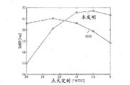
图4a、图4b以及图4c分别示出了对于在计算的发动机示例中的示例性SESI及本发动机,指示平均有效压力(IMEP)、爆震指数及热效率与开始燃烧定时的结果的关系曲线。Figures 4a, 4b, and 4c show the results of indicated mean effective pressure (IMEP), knock index, and thermal efficiency versus start of combustion timing for an exemplary SESI in the calculated engine example and the present engine, respectively.
图5示出对于施加至中等负载的气态燃料内燃发动机的不同进气门关闭定时,指示比燃料消耗(ISFC)与制动平均有效压力(BMEP)的关系曲线。FIG. 5 shows indicated specific fuel consumption (ISFC) versus brake mean effective pressure (BMEP) for different intake valve closing timings applied to a gaseous fueled internal combustion engine at a moderate load.
图6示出对于中等负载的气态燃料内燃发动机在压缩冲程期间在使用不同的进气门关闭定时的情况下模型化的缸内温度。FIG. 6 shows modeled in-cylinder temperatures during the compression stroke for a moderate load gaseous fueled internal combustion engine using different intake valve closing timings.
图7示出对于使用节流、涡轮增压器旁通和/或可变气门致动策略的不同发动机运行模式的模型化的净比燃料消耗率。FIG. 7 shows modeled net specific fuel consumption for different engine operating modes using throttling, turbocharger bypass, and/or variable valve actuation strategies.
具体实施方式Detailed ways
出于突出重点及简洁的目的,对实施方式的常规的以及对那些熟悉气态燃料发动机技术的人而言已知的某些方面不再做详细描述。For the sake of focus and brevity, certain aspects of the embodiments that are conventional and known to those familiar with gaseous fuel engine art are not described in detail.
在现有技术中,某些术语已被用在不同的上下文中及不同的出版物中以具有不同的意义。因此,在本公开的上下文中以及在本方法和设备的描述中,以下术语被定义如下:In the prior art, certain terms have been used with different meanings in different contexts and in different publications. Accordingly, in the context of this disclosure and in the description of the present method and apparatus, the following terms are defined as follows:
“化学计量”指的是与氧化剂和燃料混合物有关的情形,其中,氧化剂的总量与存在的燃料的总量相平衡,使得在被燃烧时二者都将基本上完全地被消耗。从数字上而言,总氧化剂/总燃料比优选地为1±0.1,并且更优选地为1±0.05。"Stoichiometric"refers to the situation associated with an oxidant and fuel mixture wherein the total amount of oxidant is in balance with the total amount of fuel present such that both will be substantially completely consumed when combusted. Numerically, the total oxidant/total fuel ratio is preferably 1 ± 0.1, and more preferably 1 ± 0.05.
“正常”发动机运行指的是对于发动机而言在以稳定状态运行时运行的多个常规模式(例如,空载、轻载、满载)。大多数时间里,发动机被期望运行在这些模式中的一种模式中。然而,这并不包括诸如与维护、诊断、瞬态工况等之类相关的特殊情形。“Normal” engine operation refers to a number of normal modes (eg, no load, light load, full load) for the engine to operate when operating in a steady state. Most of the time, the engine is expected to run in one of these modes. However, this does not cover special situations such as those related to maintenance, diagnostics, transient conditions, etc.
关于燃料喷射的“低压”指的是低于约50bar的压力。"Low pressure" in relation to fuel injection refers to pressures below about 50 bar.
图1示出了发动机系统1的示意图,其包括气态燃料化学计量的压燃式内燃发动机的一个实施方式的示例。在该示例中,化学计量能够部分地通过使用节流器20以控制进气的量并且部分地通过使用EGR阀15以控制被再循环的废气的量而进行控制。发动机系统1还配备有用于对通过排气门6离开燃烧室4的发动机废气进行处理的三元催化剂21。Figure 1 shows a schematic diagram of an engine system 1 comprising an example of one embodiment of a gaseous fuel stoichiometric compression ignition internal combustion engine. In this example, stoichiometry can be controlled partly by using
实际的发动机通常包括多个气缸和多个燃烧室,但是出于说明的目的,在图1中示出的内燃发动机仅包括由气缸2和往复式活塞3限定的燃烧室4。进气门5和排气门6分别允许空气/燃料混合物进入燃烧室4中以及允许燃烧废气从燃烧室4离开。发动机系统1还设有进气歧管7和排气歧管8,所述进气歧管7和排气歧管8分别流体连接到进气门5和排气门6。A real engine typically includes a number of cylinders and a number of combustion chambers, but for illustration purposes the internal combustion engine shown in FIG. 1 includes only a combustion chamber 4 defined by a
在发动机系统1中使用的主要燃料为气态燃料,所述气态燃料从主要燃料供给器9供给,并通过位于进气门5附近的主要燃料喷射器11引入到进气歧管7中。由于进气歧管7的部分通常被描述为进气口,因而示出的实施方式有时被描述为进气口喷射。在将处于该位置的气态燃料引入时,能够使用相对低的喷射压力,例如约1至15bar(度量)。由于对于诸如天然气之类的气态燃料而言进气口喷射是已熟知的,因此,主要燃料供给器9可以是为向进气口喷射器供给存储为压缩天然气或者液化天然气的燃料而开发的适当的燃料供给子系统。The main fuel used in the engine system 1 is a gaseous fuel supplied from a
仅靠压缩通常不是一种用于点燃空气/气态燃料混合物的可靠的方式。如之前相对于已知的方式讨论过的,用于辅助点燃空气/气态燃料混合物的策略是理想的。然而对于进气口喷射的气态燃料,该点火辅助通常通过火花塞来实现,本结构使用诸如柴油之类的适当的引燃燃料,所述引燃燃料经由小的共轨从引燃燃料供给器10供给并由引燃燃料喷射器12直接地引入到燃烧室4中。相对高的喷射压力——例如200至2000bar——被用于使液体柴油燃料雾化和分散并克服由于压缩冲程而在燃烧室4中存在的、与在进气歧管7中的压力相比相对较高的压力。Compression alone is generally not a reliable way to ignite an air/gaseous fuel mixture. As discussed previously with respect to known approaches, a strategy for assisting ignition of the air/gaseous fuel mixture is ideal. Whereas for port-injected gaseous fuels, this ignition assistance is usually achieved by a spark plug, the present configuration uses a suitable pilot fuel such as diesel fuel from the
发动机系统1还包括在本文中示意性地由EGR回路14和可控制的ERG阀15表示的废气再循环(EGR)子系统。如在图1中所示,准许进入进气歧管7的周围空气的量通过节流器20来调节。电子可编程发动机控制器16接收来自传感器(未示出)的信号并控制各种发动机部件,所述传感器检测诸如燃料存储箱中的燃料液位、温度、压力以及单独地或联合地指示某些发动机状况之类的某些发动机运行参数,示出了所述各种发动机部件中的一些部件,例如主要燃料喷射器11、引燃燃料喷射器12、EGR阀15、进气门5、排气门6和节流器20。在图1中,虚线代表将传感器信号发送到控制器16的信号线以及将来自控制器16的控制信号发送到所连接的发动机部件的信号线。通常认为,发动机控制器16可以用于检测其它的发动机运行参数并且控制除在文中描述的那些部件以外的部件。Engine system 1 also includes an exhaust gas recirculation (EGR) subsystem, represented schematically herein by
在正常运行中,发动机控制器16响应于由操作者确定的可变的发动机负载来控制发动机部件。控制器16基于所指令的负载确定期望的化学计量的燃烧混合物并且相应地增加或减少气态主要燃料的喷射量。另外,控制器16调节节流器20、进气门5和EGR阀15以允许期望的量的空气和稀释的废气分别进入进气歧管7中。之后,在压缩阶段期间,控制器16对引燃燃料喷射器进行操作以便获得喷射的引燃燃料的期望的量、速率和定时。During normal operation,
在正常运行期间,发动机控制器16被编程为维持化学计量的空气/燃料比并且如果控制器16检测到空气/燃料比已从化学计量偏离,则控制器16对所连接的发动机部件进行控制以恢复化学计量的氧化剂/燃料比。如本文中所描述的,控制器16可以具有其能够控制的多个部件以便调节氧化剂/燃料比,并且控制器16被编程为根据所检测到的发动机参数和所确定的发动机状况来调整这些部件中一个或多个部件。通过维持化学计量的空气/燃料比,发动机废气基本上不含氧并因此一种相对简单并低价的常规三元催化剂子系统21被用作排放物处理子系统。然而,在不脱离本技术的情况下,发动机1在短期内——诸如在冷启动期间、在废气处理装置的再生期间、在以废气催化剂温度保护模式下运行时、或者仅柴油模式下(例如,在天然气不可及时)——能够以非化学计量模式操作。During normal operation, the
取代节流器20或者除了使用节流器20以外,用于控制空气/燃料混合物的可替代的实施方式使用不同的可变气门致动策略以控制通过进气门5引入到燃烧室中的充气的量。An alternative embodiment for controlling the air/fuel mixture uses a different variable valve actuation strategy in place of or in addition to the use of
在示出的实施方式中,进气门5和排气门6的打开和关闭通过控制器16来控制。在优选的实施方式中,可变气门致动策略使得能够控制进气门的定时和升程二者。这种可变气门致动装置包括被电子地控制的电磁阀。可变气门致动策略已将额外的变量引入到发动机运行中,并具有预想不到的效果。例如,根据实验结果发现那种仅使用与常规进气门的打开定时相比提前或延迟该进气门打开的定时而不对进气门保持打开的时长进行控制的策略并不具有有益的效果。这种定时策略增加了将必要量的空气输送到燃烧室所需的泵送功或者导致燃料消耗方面的净增加,如在在延迟进气门打开的定时时所观察到的,或者其可以干扰活塞冲程,并且可以将相对高水平的剩余物引入到废气流中,如在提前进气门打开的定时时所观察到的。发现如以下进一步描述的,在将进气门打开的定时维持于在活塞进气冲程之前的约TDC(上止点)处并且提前或延迟进气门关闭的定时对于总体的发动机效率而言更有益处。In the illustrated embodiment, the opening and closing of
图2说明了对于不同的进气门致动策略而言在“上止点点火之后”(ATDCf)的曲柄角角度中测量到的进气门冲程和进气门打开持续时间。曲柄角在TDCf处为零,该TDCf指示在气缸体积在活塞的压缩冲程与动力冲程之间被最小化时的点。在图2中,360°ATDCf的曲柄角指示上止点(TDC),上止点(TDC)为在活塞进气冲程开始处的最小气缸体积的点,而540°ATDCf的曲柄角指示下止点(BDC),下止点(BDC)为在活塞进气冲程结束处的最大气缸体积的点。FIG. 2 illustrates intake valve stroke and intake valve opening duration measured in crank angle angle “after top dead center ignition” (ATDC f ) for different intake valve actuation strategies. Crank angle is zero at TDC f , which indicates the point at which cylinder volume is minimized between the compression and power strokes of the piston. In Figure 2, a crank angle of 360° ATDC f indicates top dead center (TDC), which is the point of minimum cylinder volume at the beginning of the piston intake stroke, while a crank angle of 540° ATDC f indicates Bottom Dead Center (BDC) Bottom dead center (BDC) is the point of maximum cylinder volume at the end of the piston's intake stroke.
不具有可变气门致动的常规发动机通常具有如由标记号100指示的气门升程型线,其中进气门在TDC处打开并且在BDC处或靠近BDC处关闭。使用可变气门致动策略的第一VVA实施方式由进气门升程型线200指示,并包括在与常规策略的约相同的时间打开进气门,更具体地,在进气冲程之前的约上止点(TDC)处、在360°ATDCf的曲柄角处打开进气门并且对于相同的发动机而言与由进气门升程型线100指示的常规策略相比,提早地关闭进气门。即,在该第一实施方式中,进气门在活塞的进气冲程期间在活塞已移动到BDC位置之前被关闭。该策略优选地涉及减小进气门升程。Conventional engines without variable valve actuation typically have a valve lift profile as indicated by reference numeral 100 , where the intake valve opens at TDC and closes at or near BDC. A first VVA implementation using a variable valve actuation strategy is indicated by the intake
通过进气门升程型线200示出的进气门提早关闭包括在进气冲程结束之前(BDC之前)至少20°的曲柄角处关闭进气门。优选地,通过型线200示出的进气门提早关闭包括在打开进气门后将其保持成打开20度至180度的曲柄角。Early intake valve closing, shown by intake
由进气门升程型线300指示的第二VVA实施方式包括在与由进气门升程型线100指示的常规策略约相同的时间打开进气门,更具体地,在进气冲程之前的约TDC处、在360°ATDCf的曲柄角处打开进气门,并且在压缩冲程期间较晚地关闭进气门,更具体地,在大于560°ATDCf的曲柄角处、在进气冲程结束之后(在BDC之后)20度的曲柄角处关闭进气门。进气门延迟关闭包括在进气冲程结束之后(在BDC之后)约20至120度的曲柄角处关闭进气门。在该第二VVA实施方式中,在进气门打开的部分持续时间或全部持续时间内,最大进气门升程可小于由进气门升程型线100指示的常规策略中所使用的最大进气门升程。The second VVA implementation indicated by intake
发明者的实验结果已表明通过以上描述的进气门提早关闭和进气门延迟关闭策略能够实现在低负载及高负载两种情况下的更好的燃料消耗及排放物减少。Experimental results by the inventors have shown that better fuel consumption and emission reductions at both low and high load conditions can be achieved by the early intake valve closing and late intake valve closing strategies described above.
在高负载下的发动机运行期间,不仅进气门提早关闭而且进气门延迟关闭都具有减小有效发动机压缩比的效果,使得具有在压缩结束时减小缸内温度的总体效果。通过进气门提早关闭或进气门延迟关闭,观察到能够减小在高负载下的发动机爆震的危险而无需不得不改变发动机的几何压缩比。即,本方法允许发动机以比常规的SESI发动机更高的几何压缩比运行,同时以更低的有效压缩比运行,这具有在压缩结束时减小缸内温度并防止爆震的总体效果。与燃用稀燃料混合物的发动机相比,这对于更易于产生发动机爆震的燃用化学计量燃料的发动机而言尤为有益。由于燃烧室内部的压缩过程基本上在进气过程结束时开始,因此有效压缩比被限定为在通过进气门的进气流停止时燃烧室的体积与压缩冲程结束时燃烧室的体积之间的比率。对于进气门提早关闭及进气门延迟关闭两种情况而言,如在常规的进气门升程型线中的情况一样,在通过进气门的进气流停止的时候燃烧室的体积均小于在活塞到达下止点(在压缩冲程之前)时燃烧室的体积,并且因此对于进气门提早关闭和进气门延迟关闭的有效压缩比均小于常规有效压缩比。这导致降低了燃烧期间在压缩冲程结束时的缸内温度以及尾气温度,从而减小了爆震的可能性。During engine operation at high loads, not only early intake valve closing but also late intake valve closing has the effect of reducing the effective engine compression ratio, with the overall effect of reducing in-cylinder temperature at the end of compression. By closing the intake valve early or closing the intake valve late, it was observed that the risk of engine knocking at high loads can be reduced without having to change the geometric compression ratio of the engine. That is, the present method allows the engine to operate at a higher geometric compression ratio than a conventional SESI engine while operating at a lower effective compression ratio, which has the overall effect of reducing in-cylinder temperatures at the end of compression and preventing knocking. This is particularly beneficial for engines burning stoichiometric fuels which are more prone to engine knock than engines burning lean fuel mixtures. Since the compression process inside the combustion chamber essentially begins at the end of the intake process, the effective compression ratio is defined as the difference between the volume of the combustion chamber when the flow of intake air through the intake valve stops and the volume of the combustion chamber at the end of the compression stroke ratio. For both early intake valve closing and late intake valve closing, as in the conventional intake valve lift profile, the volume of the combustion chamber is equal when the flow of intake air through the intake valve is stopped. Less than the volume of the combustion chamber when the piston reaches bottom dead center (before the compression stroke), and thus the effective compression ratio for both early intake valve closing and late intake valve closing is less than the conventional effective compression ratio. This results in lower cylinder temperatures at the end of the compression stroke during combustion, as well as exhaust gas temperatures, reducing the likelihood of knock.
为维持用于发动机的化学计量运行所需的动力,在以上所描述的气门致动策略期间引入到燃烧室中的充气量必须维持为相对恒定的以维持给定的动力输出。这可以通过对被限定为在进气歧管中的压力的增压压力进行控制来实现。由于有效压缩比被减小,为满足给定负载所需的增压压力增大。To maintain the power required for stoichiometric operation of the engine, the amount of charge introduced into the combustion chamber during the valve actuation strategies described above must be maintained relatively constant to maintain a given power output. This is achieved by controlling boost pressure, which is defined as the pressure in the intake manifold. As the effective compression ratio is reduced, the boost pressure required to satisfy a given load increases.
在处于高负载时,以上气门致动策略通常不需要使用节流调节,在处于低负载时,节流调节优选与改变进气门关闭的定时一起使用以调节引入到燃烧室中的空气的量,尤其在短的进气门打开持续时间的期间内。进气门响应时间通常比节流器响应时间更慢,因此通常在低负载时仅通过使用仅以上描述的气门致动技术更难以控制引入到燃烧室中的空气量。At high loads, the above valve actuation strategies generally do not require the use of throttle adjustments, at low loads, throttle adjustments are preferably used in conjunction with varying the timing of intake valve closing to adjust the amount of air introduced into the combustion chamber , especially during short intake valve opening durations. The intake valve response time is generally slower than the throttle response time, so it is generally more difficult to control the amount of air introduced into the combustion chamber at low loads by using only the valve actuation techniques described above.
用于在减少泵送损失的同时保持在低负载时所需的喷射到燃烧室内的充气量的另一技术为停用一些发动机气缸使得发动机以减少数量的气缸运行。气缸停用涉及增加引入到每个点火气缸的燃烧室中的充气量;这导致在进气冲程期间点火气缸的更高的缸内压力以及因此减少的泵送功。Another technique for maintaining the required amount of charge injected into the combustion chamber at low loads while reducing pumping losses is to deactivate some of the engine cylinders so that the engine operates with a reduced number of cylinders. Cylinder deactivation involves increasing the charge introduced into the combustion chamber of each firing cylinder; this results in a higher in-cylinder pressure of the firing cylinder during the intake stroke and thus reduced pumping work.
发动机系统通常包括涡轮增压器,在该涡轮增压器中,安装在排气系统中的涡轮使用废气中的焓以驱动进气系统中的压缩机,这增大了进气压力。对于这种系统而言,用于在减少由系统在低负载时所作的泵送功的同时维持引入到燃烧室中所需的充气量的另一技术为打开旁通阀(称为“废气门”)使得一些或所有的废气在离开发动机之后旁通过涡轮增压器。在旁通过涡轮增压器时,在排气管线中产生更少的背压,并因此需要更少的将废气推出燃烧室的泵送功。同样,在一些或所有废气流旁通过涡轮增压器时,供给到发动机的空气的压力保持为更低并且进气能够被输送到发动机而无需节流。Engine systems typically include a turbocharger in which a turbine installed in the exhaust system uses the enthalpy in the exhaust gas to drive a compressor in the intake system, which increases intake pressure. For such systems, another technique for maintaining the required amount of charge introduced into the combustion chamber while reducing the pumping work done by the system at low loads is to open a bypass valve (known as a "wastegate"). ”) causing some or all of the exhaust gases to bypass the turbocharger after leaving the engine. When bypassing the turbocharger, less back pressure is created in the exhaust line and thus less pumping work is required to push the exhaust gases out of the combustion chamber. Also, with some or all of the exhaust flow bypassing the turbocharger, the pressure of the air supplied to the engine remains lower and intake air can be delivered to the engine without throttling.
在图3中示出的另一替代性实施方式中,低压主要燃料喷射器11A能够被定位成使得喷嘴位于燃烧室4内,使得主要燃料喷射器阀本体安装在气缸中或安装在气缸盖中以将气态燃料引导到燃烧室中而不是使进气通过进气门5。为了避免与将气态燃料提升至更高的喷射压力相关联的增加的复杂性,根据本方法,气态燃料的喷射优选地在压缩冲程期间的早期完成。这种办法可以在使用可变气门致动策略和装置的实施方式中更为有利,由于这样的话,引入燃烧室4中的氧化剂的量被更独立于燃料的量进行控制。在图3中图示的实施方式具有许多与图1中展示的实施方式的部件相同的部件并且这些相同的部件已被标识有相同的附图标记。这些部件已经相对于图3中图示的实施方式进行了描述,并且因此其目的和功能在此不再赘述。In another alternative embodiment shown in Figure 3, the low pressure main fuel injector 11A can be positioned such that the nozzle is located within the combustion chamber 4 such that the main fuel injector valve body is mounted in the cylinder or in the cylinder head To direct gaseous fuel into the combustion chamber instead of intake air through the
与以上描述的可变进气门致动策略类似的可变进气门致动策略能够应用到用于气态燃料被直接地喷射到燃烧室中的发动机的进气门,并且在该实施方式中,进气门的关闭优选定时成先于气态燃料喷射。即,与在图2中由附图标记200所指示的进气门型线相似的进气门型线可以是优选实施方式的示例,因为这将有助于气态燃料的提早喷射。A variable intake valve actuation strategy similar to that described above can be applied to intake valves for engines where gaseous fuel is directly injected into the combustion chamber, and in this embodiment , closing of the intake valve is preferably timed to precede gaseous fuel injection. That is, an intake valve profile similar to that indicated by
又一可替代的实施方式能够使用喷射到进气歧管中的天然气脉冲宽度调制。脉冲宽度调制为普通的、价低的并且稳健的方式,以便以精确且可控的方式将燃料可靠地输送到进气歧管。Yet another alternative implementation could use pulse width modulation of natural gas injected into the intake manifold. Pulse width modulation is a common, inexpensive and robust way to reliably deliver fuel to the intake manifold in a precise and controlled manner.
本方法和设备提供了元件的独特组合。尽管每个单独元件自身可具有期望的益处,但在与其他元件相组合时,由于一个元件中的改变可能影响另一元件,因而这种益处是不确定的或会受到限制。已经发现,本方法和设备产生不同于已知气态燃料发动机的性能特征。例如,与SESI气态燃料发动机相比,柴油引燃燃料的压燃能够以更高的压缩比及增大的EGR水平运行。这进而导致降低的燃料消耗(多达5%)、更高的BMEP比率以及与在SESI发动机(主要由于燃烧爆震限制)中现行可能的效率相比更高的效率。同样,相对于SESI发动机,期望天然气质量变化的提高的稳健性(由于来自引燃燃料的燃烧的点燃能量为高于火花点燃能量的数个量级并且存在多个用于点火的位置,因此促进了更快的且更均匀的燃烧,其进而被认为导致了增加的ERG耐受度以及减小的爆震性)。与SESI发动机相比,认为由于喷射器的使用寿命通常为火花塞的数倍,因此引燃部件的耐久性应增加。至于排放物,由于化学计量的空气/燃料比在正常运行期间由允许使用常规三元催化剂排放物处理子系统的本方法和设备来维持,因此性能可以与SESI发动机的性能相同,可能的例外为由于使用少量的引燃燃料而产生的颗粒状排放物。The present method and apparatus provide a unique combination of elements. While each individual element may have desirable benefits on its own, when combined with other elements, such benefits may be uncertain or limited because changes in one element may affect the other. It has been found that the present method and apparatus yield performance characteristics that differ from known gaseous fueled engines. For example, compression ignition of diesel pilot fuel enables operation at higher compression ratios and increased EGR levels compared to SESI gaseous fueled engines. This in turn leads to reduced fuel consumption (up to 5%), higher BMEP ratios and higher efficiencies than currently possible in SESI engines (mainly due to combustion knock limitations). Also, improved robustness to gas mass variation is expected relative to SESI engines (since the ignition energy from combustion of the pilot fuel is orders of magnitude higher than the spark ignition energy and there are multiple locations for ignition, facilitating faster and more uniform combustion, which in turn is believed to lead to increased ERG tolerance and reduced knock). Compared to SESI engines, it is believed that the durability of the ignition components should be increased since the life of the injector is typically several times that of the spark plug. With respect to emissions, since the stoichiometric air/fuel ratio is maintained during normal operation by the present method and apparatus allowing the use of conventional three-way catalyst emission treatment subsystems, performance can be the same as that of a SESI engine, with the possible exception of Particulate emissions from the use of small amounts of pilot fuel.
与以稀燃模式运行的双燃料天然气发动机不同(即,在燃料混合物中具有相当多的过量的氧气),本方法和设备无需更复杂且昂贵的排放物处理子系统来满足现行排放标准。通常的双燃料排放物处理子系统使用氧化作用催化剂(氧化催化剂),选择性的催化还原(SCR),以及柴油颗粒过滤器(DPF)。因此,由本方法和设备教示的元件的独特组合提供了超过双燃料发动机的在这方面的益处。Unlike dual-fuel natural gas engines operating in lean burn mode (ie, with a substantial excess of oxygen in the fuel mixture), the present method and apparatus do not require more complex and expensive emissions treatment subsystems to meet current emission standards. A typical dual-fuel emissions treatment subsystem uses an oxidation catalyst (oxidation catalyst), selective catalytic reduction (SCR), and a diesel particulate filter (DPF). Thus, the unique combination of elements taught by the present method and apparatus provides benefits in this regard over dual fuel engines.
在现有技术的发动机选择中,HPDI气态-燃料发动机提供了优越的性能,例如,如经测量在效率和BMEP方面的优越的性能。然而,这些发动机需要高压气态燃料输送子系统以使得能够在压缩冲程中的较晚时将气态燃料直接地喷射到燃烧室中,并且这通常需要增压泵以及具有定位于燃烧室内部的喷嘴的气态燃料喷射器。在燃烧室内寻找空间以定位用于气态燃料喷射器和引燃燃料喷射器的喷嘴,在小的发动机、尤其是在气缸盖中的许多空间已被两个进气门和两个排气门占据的现代发动机中可谓一项挑战。此外,与常规柴油机相似,HPDI气态燃料发动机以分层燃烧过程进行操作,因此,HPDI气态燃料发动机通常需要更复杂且更昂贵的排放物处理子系统,其通常包括与SCR和DPF相结合的氧化催化剂。这里,再次地,由本方法和设备所教示的元件的不同结合产生了不同的结果,该结果提供了能够更容易地在较小的发动机中实施、同时仍提供有竞争力的性能的更简单且可能更低价的替代物。Among the state-of-the-art engine options, HPDI gaseous-fuel engines offer superior performance, eg, as measured in terms of efficiency and BMEP. However, these engines require a high pressure gaseous fuel delivery subsystem to enable injection of gaseous fuel directly into the combustion chamber late in the compression stroke, and this typically requires a boost pump and a fuel tank with a nozzle positioned inside the combustion chamber. Gaseous fuel injectors. Find space in the combustion chamber to position the nozzles for the gaseous fuel injector and the pilot fuel injector, in small engines, especially in the cylinder head a lot of space is already taken up by two intake and two exhaust valves A challenge in modern engines. Furthermore, similar to conventional diesel engines, HPDI gaseous fuel engines operate with a stratified combustion process, and as such, HPDI gaseous fuel engines typically require more complex and expensive emissions treatment subsystems, which typically include oxidation in combination with SCRs and DPFs catalyst. Here, again, different combinations of elements taught by the present method and apparatus yield different results in providing simpler and more easily implemented in smaller engines while still providing competitive performance. Possibly less expensive alternatives.
进一步关于所描述过的,表1通过对其某些属性和/或特征进行比较,说明了目前的本方法和设备与上述已知的发动机和操作该发动机的方法相比二者之间的一些关键差异。Further to what has been described, Table 1 illustrates some of the differences between the present method and apparatus as compared to the known engines and methods of operating the same described above, by comparing some of their attributes and/or characteristics. key difference.
表1Table 1


尽管本发动机结构的独特方法提供优于已知的气态燃料发动机的简化性和/或其它优点,也存在呈现出不同挑战的一些方面。例如,在HPDI发动机中,由于燃料通常在靠近上止点的定时直接地喷射到燃烧室中使得基本上不存在燃烧爆震的可能性,因而燃烧爆震不是一个问题。对于本发动机结构,主要气态燃料与进气一起或在发动机循环中较早时被引入到燃烧室中,使得过早爆燃——公知的燃烧爆震——成为需要被防范的一个可能性,尤其是在希望保持相对高的压缩比,以在所有相关运行条件下维持稳健的燃烧。While the unique approach of the present engine architecture offers simplicity and/or other advantages over known gaseous fuel engines, there are also aspects that present different challenges. For example, in HPDI engines, combustion knock is not a problem because fuel is usually injected directly into the combustion chamber at a timing close to top dead center so that the possibility of combustion knock is substantially non-existent. With the present engine architecture, the predominantly gaseous fuel is introduced into the combustion chamber with the intake air or early in the engine cycle, making premature detonation—known as combustion knock—a possibility that needs to be guarded against, especially It is desirable to maintain a relatively high compression ratio to maintain robust combustion under all relevant operating conditions.
与柴油机相比,减小发动机的压缩比是减少燃烧爆震可能性的一个方法,该方法通常在SESI发动机中使用并且在双燃料发动机中有较少程度的使用。然而,减小压缩比使得在所有相关的运行条件下促进强劲且可靠的燃烧更具挑战性。Reducing the compression ratio of an engine is one method of reducing the likelihood of combustion knock, generally used in SESI engines and to a lesser extent in dual fuel engines, compared to diesel engines. However, reducing the compression ratio makes it more challenging to promote robust and reliable combustion under all relevant operating conditions.
据估计,来自少量引燃柴油燃料的点燃能量可以是大于SESI发动机中火花塞的点燃能量的三个到四个量级,并且通过使用多个引燃燃料喷射喷雾器,由引燃燃料提供了更大的引燃区域。这导致了对以更高水平的EGR稀释的充气进行燃烧的提升的能力,使得与受到火花塞的点燃能量限制的SESI发动机不同,通过本方法和设备可以使用更多的EGR来抑制发动机爆震。同时,由于在再循环废气中基本上不存在取代一些新鲜空气的氧气,因此更高水平的EGR也影响空气/燃料比,于是所指令的ERG的量需要与节流器20的控制相协调。It is estimated that the ignition energy from a small amount of pilot diesel fuel can be three to four orders of magnitude greater than that of a spark plug in a SESI engine, and by using multiple pilot fuel injection sprayers, greater ignition area. This results in an increased ability to combust a charge diluted with higher levels of EGR so that, unlike SESI engines, which are limited by the ignition energy of the spark plug, more EGR can be used to suppress engine knock by the present method and apparatus. At the same time, higher levels of EGR also affect the air/fuel ratio since there is essentially no oxygen in the recirculated exhaust gas to displace some of the fresh air, so the amount of ERG commanded needs to be coordinated with the
在以下呈现的示例中,执行了燃烧计算流体动态模型,以观察本方法和设备的爆震趋势、效率和排放物。这些模拟显示本方法和设备能够获得相当高的BMEP(≥23bar)并且与常规的SESI发动机相比能够适度地提高热效率,同时仍能将燃烧爆震控制到可接受的水平。本发动机中的燃烧比常规的SESI发动机产生更高的放热率,使得最佳热效率的优化的点火定时与SESI发动机相比被推迟。这推迟了点火定时的开始使得本发动机在更高制动平均有效压力(BMEP)下以比其它相同的SESI发动机低得多的燃烧爆震指数来运行。这种优点在更高的压缩比时更明显。In the examples presented below, a computational fluid dynamics model of combustion was performed to observe the knock tendency, efficiency and emissions of the present method and apparatus. These simulations show that the present method and apparatus are capable of achieving considerably higher BMEP (≥23 bar) and moderately improved thermal efficiency compared to conventional SESI engines, while still controlling combustion knock to acceptable levels. Combustion in the present engine produces a higher rate of heat release than conventional SESI engines, so that the optimal ignition timing for best thermal efficiency is retarded compared to SESI engines. This delays the onset of ignition timing allowing the present engine to operate at a higher brake mean effective pressure (BMEP) with a much lower combustion knock index than otherwise identical SESI engines. This advantage is more pronounced at higher compression ratios.
为进一步降低燃烧爆震性,本方法和设备还允许使用数种另外的策略。由于燃烧爆震对于发动机中的缸内温度更敏感,能够减小尾气温度的策略可以是有利的。这些策略包括增加冷却EGR的量以增加充气稀释,使EGR冷却器的大小被设定为向EGR气体提供增加的冷却,增加充气空气冷却使得充气在进入气缸时在所有相关的运行条件下温度为低于60℃,如更早前描述的,通过改变气门致动降低发动机的有效压缩比。更进一步的策略包括将环窜漏减少至小于相对于在体积基础上的气流的约2%。(这是由于在窜漏中的油有助于燃烧爆震反应。)To further reduce combustion knock, the present method and apparatus allow several additional strategies to be used. Since combustion knock is more sensitive to in-cylinder temperatures in engines, strategies that can reduce exhaust gas temperatures may be advantageous. These strategies include increasing the amount of cooled EGR to increase charge dilution, having the EGR cooler sized to provide increased cooling to the EGR gases, increasing charge air cooling such that the charge enters the cylinder at a temperature of Below 60°C, the engine's effective compression ratio is reduced by varying valve actuation as described earlier. Still further strategies include reducing ring blowby to less than about 2% relative to airflow on a volume basis. (This is due to the oil in the blowby contributing to the combustion knock reaction.)
对于本方法和设备,为了抑制燃烧爆震,计算结果和试验结果暗示最好使压缩比保持低于常规柴油发动机或HPDI发动机的压缩比。因此,更难以确保喷射的引燃柴油燃料在所有相关的运行条件下会自动点火。计算显示本发动机结构对于0℃以上的发动机运行条件而言,在理论上能够点燃处于12:1至13:1之间的压缩比下的柴油。这些计算涉及确定对于多个充气温度而言压缩比对发动机气缸中的压缩结束时的温度的作用。在0℃以下,可能需要诸如缸体加热器或空气加热器之类的冷启动装置;在这种情况下并不推荐使用电热塞,因为其具有引起充气在进气活动期间点火的潜在性,从而导致在进气歧管中的不受控制的燃烧(“回火”)。控制进气门或排气门的致动的方法也可以用于通过在气缸中保持更多的热的废气而增加缸内温度并因此加强柴油引燃物的自动点火。For the present method and apparatus, in order to suppress combustion knock, calculations and test results suggest that it is desirable to keep the compression ratio lower than that of a conventional diesel or HPDI engine. Therefore, it is more difficult to ensure that the injected pilot diesel fuel will auto-ignite under all relevant operating conditions. Calculations show that the present engine configuration is theoretically capable of igniting diesel fuel at compression ratios between 12:1 and 13:1 for engine operating conditions above 0°C. These calculations involve determining the effect of the compression ratio on the temperature at the end of compression in the engine cylinders for a number of charge temperatures. Below 0°C, cold start devices such as block heaters or air heaters may be required; glow plugs are not recommended in this case due to their potential to cause the charge to ignite during intake activity, This results in uncontrolled combustion ("flashback") in the intake manifold. The method of controlling the actuation of the intake or exhaust valves can also be used to increase the in-cylinder temperature and thus enhance the auto-ignition of the diesel pilot by keeping more hot exhaust gas in the cylinder.
在使用本发动机的实施方式时,可能需要特别地考虑其它技术问题。例如,如之前讨论过的,尽管本发动机与SESI发动机相比能够更耐受于天然气合成物中的变化,但本发动机与HPDI气态燃料的发动机相比在这方面具有更低的耐受性。因此,在一些实施方式中,燃烧感测以及用于对响应于测量到的燃烧行为对发动机运行做出调整的控制策略与本发动机结构相结合会是有益的。例如,共同拥有的美国专利No.7,133,761、No.7,200,487以及No.7,444,231公开了出于该目的而使用的方法和设备的示例。同样,在使用微引燃燃料运行的情况下,将需要注意以便将引燃燃料量控制到足够小的水平,同时保持足够的脉冲宽度以及充分高的喷射压力,例如,以帮助雾化。此外,由于在某些情况下相当大地减少了引燃燃料的流动,引燃燃料喷射器优选被设计成在比常规的柴油喷射器高的温度下良好地运行和/或被设计成具有用于冷却喷射器尖端的特征或用于防止过加热和/或防止积聚碳沉淀物——也被称为“尖端碳化”——的其它特征。When using this embodiment of the engine, other technical issues may need special consideration. For example, as previously discussed, while the present engine is more tolerant to changes in natural gas composition than SESI engines, the present engine is less tolerant in this regard than HPDI gaseous fueled engines. Accordingly, in some embodiments, combustion sensing and a control strategy for making adjustments to engine operation in response to measured combustion behavior may be beneficial in conjunction with the present engine architecture. For example, commonly owned US Patent Nos. 7,133,761, 7,200,487, and 7,444,231 disclose examples of methods and apparatus used for this purpose. Also, in the case of micro-pilot fuel operation, care will be required to control the amount of pilot fuel to a sufficiently small level while maintaining sufficient pulse width and sufficiently high injection pressure, eg, to aid atomization. Furthermore, pilot fuel injectors are preferably designed to operate well at higher temperatures than conventional diesel injectors and/or are designed to have Features to cool the injector tip or other features to prevent overheating and/or prevent buildup of carbon deposits, also known as "tip carburization".
另一技术挑战涉及发动机系统的准确控制,由于引燃柴油的存在,其被预期为比用于SESI发动机的准确控制更复杂。无论如何,尽管本方法和设备需要独特的控制策略,但已存在用于管理两种不同燃料的技术,诸如为HPDI气态燃料发动机开发的使用主要气态燃料和用于点火的引燃燃料的技术。并且同样,尽管本方法和设备的实施方式可以包括与用于现有技术中的发动机的步骤和部件相同的步骤和部件,为反映元件的本组合的独特性,步骤的组合与控制不同元件的方式是不同的。例如,在这种事情中标准方法可以用作确定最优压缩比(以在通常运行条件下实现引燃点火,同时抑制燃烧爆震并且获得尽可能高的BMEP和尽可能低的甲烷值运行)、优选的喷射器设计(例如喷射孔的数量、形状和构型)、以及活塞碗状和涡流比(应当指出,由于引燃燃料喷射受到活塞形状的干涉,因此在一些SESI发动机中使用的反向星云活塞形状将极有可能不适于本发动机构型)。Another technical challenge relates to the accurate control of the engine system, which is expected to be more complex than that for SESI engines due to the presence of pilot diesel. Regardless, while the present method and apparatus require unique control strategies, techniques already exist for managing two different fuels, such as those developed for HPDI gaseous fueled engines using a primary gaseous fuel and a pilot fuel for ignition. And also, while embodiments of the method and apparatus may include the same steps and components as are used in prior art engines, to reflect the uniqueness of this combination of elements, the combination of steps is not related to controlling the different elements The way is different. For example, standard methods can be used in such matters to determine the optimum compression ratio (to achieve pilot ignition under normal operating conditions while suppressing combustion knock and obtaining the highest possible BMEP and the lowest possible methane number operation) , preferred injector design (e.g. number, shape and configuration of injection holes), and piston bowl and swirl ratio (it should be noted that the reverse The shape of the Xingyun piston will most likely not be suitable for this engine configuration).
提供以下示例以说明本方法和设备的某些方面,但以下示例不应被解释为任何方式的限制。The following examples are provided to illustrate certain aspects of the methods and devices, but should not be construed as limiting in any way.
计算的发动机示例Calculated engine example
执行了数字研究以观察在可比的条件下运行的SESI发动机和本技术的发动机的燃烧爆震趋势以及发动机的效率。该研究涉及两个区域预混合燃烧模式的使用并且将重点放在高的BMEP范围(20-30bar)。所述两个区域的燃烧模式在JSME国际期刊,Vol.46,No.1,2003,Catania,A.E.,Misul,D.,Mittica,A.and Spessa,E.,“ARefined Two zone Heat Release Model for Combustion Analysis inS1Engines”(“一种用于在SI发动机中的燃烧分析的改进的双区域热释放模型”)中描述,并且被修改以探索更广的参数空间来评估本燃烧策略与火花点火燃烧二者。火焰的传播基于根据局部混合温度、压力以及根据经验模型确定的湍流皱折因数计算的层流火焰速度而建模。柴油喷射和燃烧通过加速由柴油喷雾器所覆盖的投射体积内火焰的传播而建模。在给定的条件下,潜在爆震强度特征在于压力的投射比在尾气中上升。在该示例中估算的爆震强度代表假定尾气在一个特征时间范围内被消耗而来自尾气的潜在的能量释放速率。所述特征时间范围为尾气的自动点火延迟时间。Numerical studies were performed to observe the combustion knock tendency and the efficiency of the engines of the SESI engine and the engine of the present technology operating under comparable conditions. The study involved the use of two zone premixed combustion modes and focused on the high BMEP range (20-30 bar). The combustion model of the two zones is described in JSME International Journal, Vol.46, No.1, 2003, Catania, A.E., Misul, D., Mittica, A. and Spessa, E., "ARefined Two zone Heat Release Model for Combustion Analysis in S1 Engines" ("An Improved Two-Region Heat Release Model for Combustion Analysis in SI Engines"), and was modified to explore a wider parameter space to evaluate the present combustion strategy versus spark-ignition combustion. By. The propagation of the flame is modeled based on the laminar flame velocity calculated from the local mixing temperature, pressure, and turbulent wrinkling factor determined from an empirical model. Diesel injection and combustion are modeled by accelerating the propagation of flames within the projected volume covered by diesel atomizers. Under given conditions, the potential knock intensity is characterized by the projection ratio of pressure rising in the exhaust gas. The estimated knock intensity in this example represents the potential energy release rate from the exhaust assuming the exhaust is consumed within a characteristic time frame. The characteristic time range is the auto-ignition delay time of the exhaust gas.
在该研究中使用的发动机几何结构、运行条件和参数在表2中总结如下:The engine geometry, operating conditions and parameters used in this study are summarized in Table 2 as follows:
表2Table 2


根据该详细研究,获得以下示例性结果。以下表3示出对于燃用具有87的甲烷值的天然气燃料的两种发动机类型的以bar为单位的指示平均有效压力(IMEP)的比较,所述两种发动机类型均处于大约峰值热效率(即,T吸入=350°K)处且具有在康明斯西港ISLG商业发动机中使用的活塞设计,并且点火定时对于SESI发动机和本发动机而言分别为在上止点之前22°和5°的曲柄角(CABTDC)处。From this detailed study, the following exemplary results were obtained. Table 3 below shows a comparison of indicated mean effective pressure (IMEP) in bar for two engine types fired on natural gas fuel with a methane number of 87, both at approximately peak thermal efficiency (i.e. , Tsuction = 350°K) with the piston design used in the Cummins Westport ISLG commercial engine, and the ignition timing is 22° and 5° crank angle before top dead center for the SESI engine and this engine, respectively ( CABTDC).
表3table 3
另外,图4a、图4b和图4c分别示出在相同的条件——即320°K的进气温度、14:1的压缩比和87的甲烷值——下运行的SESI发动机和本发动机的实施方式的IMEP、爆震指数、热效率对开始燃烧定时的结果。In addition, Figure 4a, Figure 4b and Figure 4c show the SESI engine and the present engine operating under the same conditions, i.e. 320°K intake air temperature, 14:1 compression ratio, and 87 methane number, respectively. Results of IMEP, Knock Index, Thermal Efficiency versus Start Combustion Timing for an embodiment.
图4a、图4b、和图4c中明显的是,本发动机展示出在点火定时的宽范围内的改进的IMEP和热效率。本发动机和SESI发动机的峰值效率在该示例中分别发生在10°和22°CA BTDC的开始燃烧定时处。在这些定时处,SESI发动机的爆震指数好于本发动机的爆震指数。然而,在5°CA BTDC处,本发动机的IMEP和热效率仍接近其峰值并且仍优于SESI发动机峰值并且本发动机的爆震指数显著地低于SESI发动机在其峰值处的爆震指数。此外,尽管研究了比在图4a至图4c中示出的条件更多的条件,但在研究的条件中,获得的结果从质量上来讲是相同的。即,本发动机在10°CABTDC处示出峰值IMEPs,但是在该处具有比SESI发动机在其峰值IMEPs处更差的爆震指数。然而,在5°的CA BTDC处,在各种情况下,本发动机具有接近其峰值并且仍优于可比的SESI发动机峰值的IMEP,同时爆震指数基本上优于SESI发动机在其峰值处的爆震指数。As evident in Figures 4a, 4b, and 4c, the present engine exhibits improved IMEP and thermal efficiency over a wide range of ignition timing. Peak efficiencies for the present engine and the SESI engine occur at start-of-combustion timings of 10° and 22° CA BTDC, respectively, in this example. At these timings, the knock index of the SESI engine is better than that of the present engine. However, at 5° CA BTDC, the IMEP and thermal efficiency of the present engine are still close to their peak and still better than the SESI engine peak and the knock index of the present engine is significantly lower than that of the SESI engine at its peak. Furthermore, although more conditions than those shown in Figures 4a to 4c were studied, the results obtained were qualitatively the same among the conditions studied. That is, the present engine shows peak IMEPs at 10° CABTDC, but has a worse knock index there than the SESI engine at its peak IMEPs. However, at a CA BTDC of 5°, in each case, the present engine has an IMEP that is close to its peak and still better than that of the comparable SESI engine peak, while the knock index is substantially better than that of the SESI engine at its peak shock index.
这些实验性的结果示出本发动机和方法在所研究的运行条件下,能够意料不到地提供更好的IMEP和热效率以及减小的爆震性。These experimental results show that the present engine and method can unexpectedly provide better IMEP and thermal efficiency and reduced knock under the operating conditions studied.
根据研究条件,认为与可比较的SESI发动机相比,本发动机通常能够获得高的IMEP,并适中地提高热效率。在本发动机内的燃烧产生比在SESI发动机中更高的热释放率使得用于最佳热效率的最优的点火定时对于前者比对于后者延迟。这种开始点火定时的延迟允许本发动机以更高的IMEP及热效率运行,并具有比其它相同的SESI发动机具有更低的爆震指数。这种优点在更高的压缩比下更显著。关于排放物,研究表明本发动机与运行在相同条件下的常规的SESI发动机相比潜在性地具有离开燃烧室的更高水平的NOx,一氧化碳(CO)以及颗粒状物质(PM)。但是在常规的三元催化剂排放物处理之后,基于这种处理子系统的已知的性能特征,与SESI发动机相比较,认为来自本发动机系统的尾管排放物水平将大致相同或更低。另外,关于未燃烧的氢碳化合物的排放,来自计算的模型的结果表明本发动机与SESI发动机之间的差异是不显著的。Based on the study conditions, it is believed that the present engine is generally capable of achieving high IMEP with a modest increase in thermal efficiency compared to a comparable SESI engine. Combustion in the present engine produces a higher rate of heat release than in the SESI engine so that the optimal ignition timing for best thermal efficiency is retarded for the former than for the latter. This retardation of start-of-ignition timing allows the present engine to operate at higher IMEP and thermal efficiency with a lower knock index than otherwise identical SESI engines. This advantage is more pronounced at higher compression ratios. Regarding emissions, studies have shown that the present engine has potentially higher levels of NOx , carbon monoxide (CO) and particulate matter (PM) leaving the combustion chamber than a conventional SESI engine operating under the same conditions. But after conventional three-way catalyst exhaust treatment, it is believed that tailpipe emission levels from the present engine system will be about the same or lower compared to SESI engines based on the known performance characteristics of this treatment subsystem. In addition, with regard to the emissions of unburned hydrocarbons, the results from the calculated model show that the difference between the present engine and the SESI engine is insignificant.
建模结果Modeling results
在配备有可变几何涡轮增压器、废气再循环回路、并设置有位于歧管中的单喷射器的6缸中等负载发动机上所做的建模工作已证明进气门提早关闭或进气门延迟关闭与以诸如由图2中附图标记100示出的常规进气门升程型线操作的发动机相比使整个发动机效率和燃油消耗得到改进。图5中图示的建模结果表明与使用相同发动机的更常规的气门操纵相比,对于进气门提前关闭(EIVC)和进气门延迟关闭(LIVC)二者而言,在宽范围的BMEP值上节约了燃油消耗。Modeling work on a 6-cylinder medium load engine with a variable geometry turbocharger, exhaust gas recirculation circuit, and a single injector in the manifold has demonstrated early intake valve closing or intake The delayed door closing results in improved overall engine efficiency and fuel consumption compared to an engine operating with a conventional intake valve lift profile such as shown by reference numeral 100 in FIG. 2 . The modeling results illustrated in Figure 5 show that for both early intake valve closing (EIVC) and late intake valve closing (LIVC) over a wide range of Fuel consumption is saved on BMEP value.
图6进一步图示了在压缩冲程期间,对于不同的进气门致动技术的缸内温度的增加。在压缩冲程期间,在燃烧室的体积随着活塞移动离开下止点(BDC)而减小时,EIVC以及LIVC二者的缸内温度在压缩冲程结束时比在标准的发动机运行压缩冲程结束时的缸内温度更低。EIVC和LIVC二者在压缩冲程结束时的缸内温度与在发动机以低压缩比(例如,12.7:1,与标准EIVC和LIVC运行使用的压缩比14:1相比)运行时所记载的压缩冲程结束时的缸内温度相等。在该模拟中,EIVC模型涉及在约500°ATDCf时关闭进气门,而LIVC模型涉及在约630°ATDCf时关闭进气门。FIG. 6 further illustrates the increase in cylinder temperature during the compression stroke for different intake valve actuation techniques. During the compression stroke, when the volume of the combustion chamber decreases as the piston moves away from bottom dead center (BDC), the in-cylinder temperature of both EIVC and LIVC is higher at the end of the compression stroke than at the end of the compression stroke in standard engine operation The temperature in the cylinder is lower. The in-cylinder temperature at the end of the compression stroke for both EIVC and LIVC is comparable to the recorded compression when the engine is running at a low compression ratio (eg, 12.7:1 compared to 14:1 used for standard EIVC and LIVC operation). The cylinder temperature at the end of the stroke is equal. In this simulation, the EIVC model involved closing the intake valves at approximately 500° ATDC f , while the LIVC model involved closing the intake valves at approximately 630° ATDC f .
图7中图示的建模结果表明使用可变气门致动(VVA)与旁通涡轮增压器相结合来操作发动机获得了最佳的燃料消耗结果,尤其对于更低的BMEPs而言。单独使用涡轮增压器旁通或可变气门致动技术也取得了在BMEP值的宽范围上的燃料消耗上的改进。The modeling results illustrated in Fig. 7 indicate that operating the engine using variable valve actuation (VVA) in combination with a bypass turbocharger yields the best fuel consumption results, especially for lower BMEPs. Improvements in fuel consumption over a wide range of BMEP values have also been achieved using turbocharger bypass or variable valve actuation techniques alone.
实际发动机示例Actual engine example
研究用发动机被从6气缸、15L发动机转化为在单个气缸上操作(因此大小上为2.5L)。该发动机以不同的模式来操作,以天然气作为主要燃料并且将喷射的常规的柴油燃料用作引燃物。发动机以化学计量模式在以下条件下操作。The research engine was converted from a 6 cylinder, 15L engine to operate on a single cylinder (hence 2.5L in size). The engine was operated in different modes, with natural gas as the main fuel and regular diesel fuel injected as the pilot. The engine is operated in stoichiometric mode under the following conditions.
表4Table 4


研究用发动机在化学计量条件下、在低速到中速以及低范围到中范围的负载条件下成功地运行而无需改变发动机硬件。The research engine was successfully operated under stoichiometric conditions, at low to medium speeds and low to mid range load conditions without changes to the engine hardware.
这是非优化的研究用发动机并且并未使用天然气进气口喷射器。另外,在仅对一个气缸操作的该6气缸发动机中遇到了比在量产发动机中所预想到的更高的摩擦力。因此,在估算量产发动机中期望的结果是有困难的。不过,该发动机在从上止点(CA ATDC)之后0至12度的曲柄角范围内的50%IHR(综合热释放)上能够获得介于约200与250g/kw-hr之间的热效率GISFC(总指示比燃料消耗)。使用这些热效率的值并且假定在量产发动机中将获得3%的期望的提高,用于以这种化学计量模式操作的量产发动机的制动效率被估计为28%。因此,认为实验结果表明当在实际条件下,在以所述的化学计量模式操作时能够获得有竞争力的制动效率。This is a non-optimized research engine and does not use natural gas port injectors. In addition, higher friction forces are encountered in this 6-cylinder engine operating on only one cylinder than would be expected in a production engine. Therefore, there are difficulties in estimating the expected results in production engines. However, the engine is capable of achieving a thermal efficiency GISFC between about 200 and 250 g/kw-hr at 50% IHR (Integrated Heat Relief) in the crank angle range from 0 to 12 degrees after top dead center (CA ATDC) (total indicated specific fuel consumption). Using these values for thermal efficiency and assuming that a desired improvement of 3% would be obtained in a production engine, the braking efficiency for a production engine operating in this stoichiometric mode was estimated to be 28%. Therefore, the experimental results are considered to show that a competitive braking efficiency can be obtained when operating in the stoichiometric mode described under practical conditions.
在所获得的数据的基础上,也做出了以下的总体观察:On the basis of the data obtained, the following general observations were also made:
●燃烧定时主要由柴油喷射定时来确定Combustion timing is mainly determined by diesel injection timing
●气体喷射定时主要确定混合过程的完全性●Gas injection timing mainly determines the completeness of the mixing process
●增大的柴油流率使燃烧定时更早●Increased diesel flow rate enables earlier combustion timing
●更高的柴油流率帮助提高开始阶段的燃烧稳定性,这是由于更具重复性和更可靠的点火●Higher diesel flow rates help improve combustion stability at the start due to more repeatable and reliable ignition
●在引燃物开始喷射的固定定时(PSOI)下,甲烷排放物随着因较为完全混合致使气态燃料开始喷射(GSOI)的定时的提前而减少At fixed timing of pilot start of injection (PSOI), methane emissions decrease as the timing of gaseous fuel start of injection (GSOI) is advanced due to more complete mixing
●在固定的GSOI下,甲烷排放物由于不完全燃烧而随着延迟的PSOI增加● At fixed GSOI, methane emissions increase with delayed PSOI due to incomplete combustion
●更高的柴油流率也帮助减少甲烷排放●Higher diesel flow rates also help reduce methane emissions
●由于更低的燃烧温度,延迟的燃烧定时产生更低的NOX排放物●Delayed combustion timing produces lower NOx emissions due to lower combustion temperature
●对于以更高的柴油流进行的测试而言,PM排放物高得多●PM emissions are much higher for tests with higher diesel flow
●燃料消耗随着延迟的燃烧定时(即,延迟的PSOI)而恶化。• Fuel consumption worsens with retarded combustion timing (ie retarded PSOI).
在该说明书中参照的前述美国专利、外国专利文献中以及非专利出版物中的每一者,其全部内容在此通过参引并入本文中。Each of the aforementioned US patents, foreign patent documents, and non-patent publications referred to in this specification is hereby incorporated by reference herein in its entirety.
尽管已经示出和描述了本发明的特定的元件、实施方式及应用,但应当理解,在不脱离本公开的范围的情况下,特别是在前述教示的启发下,本领域技术人员能够做出许多改型,因此本发明不限于所述特定的元件、实施方式及应用。While particular elements, implementations, and applications of the present invention have been shown and described, it should be understood that those skilled in the art can make and implement without departing from the scope of the present disclosure, particularly in light of the foregoing teachings. Many variations are possible, so the invention is not limited to the particular elements, implementations and applications described.
Claims (35)
Applications Claiming Priority (3)
| Application Number | Priority Date | Filing Date | Title |
|---|---|---|---|
| US37425710P | 2010-08-16 | 2010-08-16 | |
| US61/374,257 | 2010-08-16 | ||
| PCT/CA2011/050495 WO2012021990A1 (en) | 2010-08-16 | 2011-08-12 | Gaseous-fuelled stoichiometric compression ignition internal combustion engine |
Publications (2)
| Publication Number | Publication Date |
|---|---|
| CN103154474A true CN103154474A (en) | 2013-06-12 |
| CN103154474B CN103154474B (en) | 2016-02-17 |
Family
ID=45604661
Family Applications (1)
| Application Number | Title | Priority Date | Filing Date |
|---|---|---|---|
| CN201180049257.0A Active CN103154474B (en) | 2010-08-16 | 2011-08-12 | The method of the stoichiometric explosive motor of vaporized fuel and operation explosive motor |
Country Status (6)
| Country | Link |
|---|---|
| US (1) | US8555852B2 (en) |
| EP (1) | EP2606215B1 (en) |
| CN (1) | CN103154474B (en) |
| AU (1) | AU2011291406B2 (en) |
| CA (1) | CA2807879C (en) |
| WO (1) | WO2012021990A1 (en) |
Cited By (9)
| Publication number | Priority date | Publication date | Assignee | Title |
|---|---|---|---|---|
| CN105697095A (en) * | 2014-12-15 | 2016-06-22 | 曼卡车和巴士奥地利股份公司 | Method for controlling an engine braking device and engine braking device |
| CN106687672A (en) * | 2014-09-18 | 2017-05-17 | 株式会社 Ihi | Reciprocating engine |
| CN106894889A (en) * | 2015-12-21 | 2017-06-27 | 大众汽车有限公司 | The operation method and internal combustion engine of internal combustion engine |
| CN108843428A (en) * | 2018-06-01 | 2018-11-20 | 西安交通大学 | Distributed gas energy utilization system and method based on combustion with meagre oxygen catalysis oxidation |
| CN109983213A (en) * | 2016-11-17 | 2019-07-05 | 瓦锡兰芬兰有限公司 | The method and piston engine of operated piston engine in gas mode |
| CN112049734A (en) * | 2019-06-06 | 2020-12-08 | 卡特彼勒公司 | Controlling pilot fuel injection in an engine |
| CN114510799A (en) * | 2022-01-26 | 2022-05-17 | 北京理工大学 | Free piston engine thermal efficiency improving method based on driving process control |
| CN115045752A (en) * | 2022-06-30 | 2022-09-13 | 东风柳州汽车有限公司 | Engine combustion system |
| CN115329507A (en) * | 2022-10-14 | 2022-11-11 | 潍柴动力股份有限公司 | Intake valve profile design method and intake valve |
Families Citing this family (59)
| Publication number | Priority date | Publication date | Assignee | Title |
|---|---|---|---|---|
| US8584648B2 (en) | 2010-11-23 | 2013-11-19 | Woodward, Inc. | Controlled spark ignited flame kernel flow |
| US9476347B2 (en) | 2010-11-23 | 2016-10-25 | Woodward, Inc. | Controlled spark ignited flame kernel flow in fuel-fed prechambers |
| US9172217B2 (en) | 2010-11-23 | 2015-10-27 | Woodward, Inc. | Pre-chamber spark plug with tubular electrode and method of manufacturing same |
| US9920683B2 (en) * | 2014-02-26 | 2018-03-20 | General Electric Company | Systems and method for controlling auto-ignition |
| DE102012001650B4 (en) * | 2012-01-27 | 2019-06-19 | Audi Ag | Method for operating an internal combustion engine and internal combustion engine |
| JP6073067B2 (en) * | 2012-03-29 | 2017-02-01 | 大阪瓦斯株式会社 | Engine and fuel supply method thereof |
| WO2014040606A1 (en) * | 2012-09-12 | 2014-03-20 | Volvo Lastvagnar Aktiebolag | Apparatus and method for knock control |
| WO2014056103A1 (en) * | 2012-10-09 | 2014-04-17 | Westport Power Inc. | Fuel system protection in a multi-fuel internal combustion engine |
| JP6089640B2 (en) | 2012-11-30 | 2017-03-08 | いすゞ自動車株式会社 | Natural gas engine and method of operating natural gas engine |
| JP6089639B2 (en) * | 2012-11-30 | 2017-03-08 | いすゞ自動車株式会社 | Natural gas engine and method of operating natural gas engine |
| US9422874B2 (en) * | 2012-12-05 | 2016-08-23 | Electromotive, Inc. | Simplified method to inject ethanol or other solution additives into diesel engines equipped with a digital data bus |
| CN104968913B (en) | 2012-12-07 | 2018-04-06 | 乙醇推动系统有限责任公司 | For reducing the tuned port injection system of the particle from turbo-charged direct injection formula petrol engine |
| US9441570B2 (en) | 2012-12-07 | 2016-09-13 | Ethanol Boosting Systems, Llc | Gasoline particulate reduction using optimized port and direct injection |
| US9169794B2 (en) * | 2012-12-10 | 2015-10-27 | Caterpillar Inc. | Temperature-controlled exhaust gas recirculation system and method for dual fuel engine |
| US9856848B2 (en) | 2013-01-08 | 2018-01-02 | Woodward, Inc. | Quiescent chamber hot gas igniter |
| US9200560B2 (en) * | 2013-01-11 | 2015-12-01 | Caterpillar Inc. | Gaseous common rail fuel system and high compression ratio engine using same |
| CN103195553B (en) * | 2013-04-01 | 2015-10-28 | 清华大学 | Low-temperature combustion method and system for igniting upgraded natural gas with high cetane number fuel |
| US9765682B2 (en) | 2013-06-10 | 2017-09-19 | Woodward, Inc. | Multi-chamber igniter |
| US9382857B2 (en) | 2013-12-18 | 2016-07-05 | Ford Global Technologies, Llc | Post fuel injection of gaseous fuel to reduce exhaust emissions |
| KR101542979B1 (en) * | 2013-12-26 | 2015-08-10 | 현대자동차 주식회사 | Engine Control Apparatus having Turbocharger and Method Thereof |
| CN113482763B (en) | 2014-02-26 | 2023-10-13 | 西港燃料系统加拿大公司 | Combustion device for an internal combustion engine supplied with gaseous fuel |
| CA2847630C (en) | 2014-03-21 | 2015-03-03 | Westport Power Inc. | Method and system for operating gaseous-fuelled direct injection internal combustion engine |
| US9903262B2 (en) | 2014-04-07 | 2018-02-27 | The Board Of Trustees Of The Leland Stanford Junior University | Stoichiometric high-temperature direct-injection compression-ignition engine |
| US10119496B2 (en) * | 2014-04-15 | 2018-11-06 | Cummins Inc. | Cryogenic fuel injection and combustion |
| GB2527283B (en) | 2014-06-10 | 2020-12-09 | Cummins Inc | Exhaust parameter based dual fuel engine power virtual sensor |
| AT516289B1 (en) * | 2014-10-06 | 2016-07-15 | Ge Jenbacher Gmbh & Co Og | Method for operating an auto-ignition internal combustion engine |
| AT516490B1 (en) * | 2014-12-19 | 2016-06-15 | Ge Jenbacher Gmbh & Co Og | Method for operating a spark-ignited internal combustion engine |
| AT516543B1 (en) * | 2014-12-19 | 2021-01-15 | Innio Jenbacher Gmbh & Co Og | Method for operating a spark-ignited internal combustion engine |
| JP6292408B2 (en) * | 2015-01-09 | 2018-03-14 | マツダ株式会社 | Engine control device |
| CA2881529C (en) | 2015-02-10 | 2016-04-19 | Westport Power Inc. | Reducing unburned hydrocarbon emissions in gaseous fuelled lean-burn engines |
| EP3081790B1 (en) * | 2015-02-20 | 2025-12-31 | WinGD Ltd. | Bivalent marine combustion engine with exhaust gas recirculation to suppress pre-ignition |
| US9653886B2 (en) | 2015-03-20 | 2017-05-16 | Woodward, Inc. | Cap shielded ignition system |
| JP6580701B2 (en) | 2015-03-20 | 2019-09-25 | ウッドワード, インコーポレーテッドWoodward, Inc. | Parallel pre-combustion chamber ignition system |
| JP6517117B2 (en) * | 2015-09-16 | 2019-05-22 | ヤンマー株式会社 | Engine equipment |
| US10227934B2 (en) * | 2015-09-29 | 2019-03-12 | Cummins Inc. | Dual-fuel engine combustion mode transition controls |
| US9822727B2 (en) * | 2015-10-29 | 2017-11-21 | General Electric Company | Method and systems for adjusting engine cylinder operation based on a knock sensor output |
| US9890689B2 (en) * | 2015-10-29 | 2018-02-13 | Woodward, Inc. | Gaseous fuel combustion |
| JP6436122B2 (en) * | 2016-03-28 | 2018-12-12 | トヨタ自動車株式会社 | Internal combustion engine |
| US9856835B1 (en) | 2016-07-01 | 2018-01-02 | Caterpillar Inc. | Fuel supply system for an engine with an electric ignition power source |
| JP6657040B2 (en) * | 2016-07-14 | 2020-03-04 | ヤンマー株式会社 | engine |
| WO2018058015A1 (en) | 2016-09-26 | 2018-03-29 | Ethanol Boosting Systems, Llc | Gasoline particulate reduction using optimized port fuel injection plus direct injection |
| JP2018204471A (en) * | 2017-05-31 | 2018-12-27 | マツダ株式会社 | Compression ignition type engine and control method for compression ignition type engine |
| JP6451782B2 (en) * | 2017-05-31 | 2019-01-16 | マツダ株式会社 | Compression ignition engine |
| JP6451781B2 (en) * | 2017-05-31 | 2019-01-16 | マツダ株式会社 | Compression ignition engine and control method of compression ignition engine |
| WO2020023639A1 (en) | 2018-07-24 | 2020-01-30 | Cummins Inc. | Two point fuel system for gas power generation |
| US10934966B2 (en) | 2019-02-19 | 2021-03-02 | Caterpillar Inc. | Combustion phasing control for high substitution lean burn of gaseous fuels in dual fuel engine |
| US10823106B1 (en) | 2019-05-13 | 2020-11-03 | Caterpillar Inc. | Early pilot lean burn strategy in dual fuel engine using targeted pilot flames |
| CA3140048A1 (en) | 2019-05-15 | 2020-11-19 | Clearflame Engines, Inc. | Cold-start for high-octane fuels in a diesel engine architecture |
| GB2592880B (en) * | 2019-11-22 | 2022-12-07 | Caterpillar Motoren Gmbh & Co | Method and gas fuel injection unit for operating an internal combustion engine |
| CN111305977A (en) * | 2020-02-18 | 2020-06-19 | 哈尔滨工程大学 | Hydrogen natural gas full-proportion variable dual-fuel engine |
| JP2023516273A (en) | 2020-02-26 | 2023-04-19 | クリアフレーム エンジンズ,インコーポレイテッド | Fuel independent compression ignition engine |
| BR112023000330A2 (en) | 2020-07-09 | 2023-03-28 | Clearflame Engines Inc | CYLINDER DEACTIVATION SYSTEMS AND METHODS IN ENGINES WITH HIGH TEMPERATURE MIXTURE CONTROL |
| EP4314524A1 (en) * | 2021-03-26 | 2024-02-07 | Jaguar Land Rover Limited | A piston for a lean-burn gasoline engine |
| US11359590B1 (en) | 2021-05-26 | 2022-06-14 | Caterpillar Inc. | Igniter for dual fuel engine having liquid fuel outlet checks and spark ignition source |
| JP7213929B1 (en) * | 2021-09-21 | 2023-01-27 | ヤンマーホールディングス株式会社 | Engine system and gaseous fuel combustion method |
| JP7445099B2 (en) * | 2021-12-10 | 2024-03-07 | 株式会社クボタ | diesel engine |
| GB2619025B (en) * | 2022-05-23 | 2024-06-05 | Phinia Delphi Luxembourg Sarl | Method of operating a hydrogen internal combustion engine |
| EP4390101A1 (en) * | 2022-12-19 | 2024-06-26 | Winterthur Gas & Diesel Ltd. | Internal combustion engine |
| CN119532043B (en) * | 2024-12-03 | 2026-03-20 | 潍柴动力股份有限公司 | Dual-fuel injection system, control method, control device and vehicle |
Citations (7)
| Publication number | Priority date | Publication date | Assignee | Title |
|---|---|---|---|---|
| WO1995027128A1 (en) * | 1994-04-04 | 1995-10-12 | William Galen Ii Brown | Three-way catalytic oxidizer for diesel engines |
| US5875743A (en) * | 1997-07-28 | 1999-03-02 | Southwest Research Institute | Apparatus and method for reducing emissions in a dual combustion mode diesel engine |
| US5937800A (en) * | 1998-03-06 | 1999-08-17 | Caterpillar Inc. | Method for enabling a substantially constant total fuel energy rate within a dual fuel engine |
| US20030084876A1 (en) * | 2001-11-06 | 2003-05-08 | Stanglmaier Rudolf H | Method and apparatus for operating a diesel engine under stoichiometric or slightly fuel-rich conditions |
| CN1460149A (en) * | 2000-02-11 | 2003-12-03 | 韦斯特波特研究公司 | Method and apparatus for gaseous fuel injection into IC engine and controlling combustion |
| US20050263139A1 (en) * | 2003-07-16 | 2005-12-01 | Southwest Research Institute | High-efficiency, low emission gasoline engines for heavy-duty applications |
| US20070039588A1 (en) * | 2002-07-04 | 2007-02-22 | Toyota Jidosha Kabushiki Kaisha | Internal combustion engine of compressing and auto-igniting air-fuel mixture and method of controlling such internal combustion engine |
Family Cites Families (22)
| Publication number | Priority date | Publication date | Assignee | Title |
|---|---|---|---|---|
| KR950004533B1 (en) * | 1990-11-30 | 1995-05-02 | 미쯔비시 지도샤 고교 가부시끼가이샤 | Exhaust gas treatment device of diesel engine |
| US5365902A (en) * | 1993-09-10 | 1994-11-22 | General Electric Company | Method and apparatus for introducing fuel into a duel fuel system using the H-combustion process |
| US6161378A (en) * | 1996-06-10 | 2000-12-19 | Hitachi, Ltd. | Exhaust gas purification apparatus of internal combustion engine and catalyst for purifying exhaust gas internal combustion engine |
| US6073862A (en) | 1998-09-16 | 2000-06-13 | Westport Research Inc. | Gaseous and liquid fuel injector |
| US6761325B2 (en) | 1998-09-16 | 2004-07-13 | Westport Research Inc. | Dual fuel injection valve and method of operating a dual fuel injection valve |
| US6640773B2 (en) * | 2000-12-26 | 2003-11-04 | Westport Research Inc. | Method and apparatus for gaseous fuel introduction and controlling combustion in an internal combustion engine |
| AU2001261245A1 (en) * | 2000-05-08 | 2001-11-20 | Cummins, Inc. | Multiple operating mode engine and method of operation |
| AU2002224786A1 (en) | 2000-10-22 | 2002-04-29 | Westport Germany Gmbh | Internal combustion engine with injection of gaseous fuel |
| US6439192B1 (en) | 2000-10-24 | 2002-08-27 | Westport Research Inc. | Gaseous and liquid fuel injection valve with concentric needles |
| US6912992B2 (en) * | 2000-12-26 | 2005-07-05 | Cummins Westport Inc. | Method and apparatus for pilot fuel introduction and controlling combustion in gaseous-fuelled internal combustion engine |
| US6598584B2 (en) * | 2001-02-23 | 2003-07-29 | Clean Air Partners, Inc. | Gas-fueled, compression ignition engine with maximized pilot ignition intensity |
| US6550430B2 (en) * | 2001-02-27 | 2003-04-22 | Clint D. J. Gray | Method of operating a dual fuel internal |
| US6378489B1 (en) * | 2001-05-24 | 2002-04-30 | Rudolf H. Stanglmaier | Method for controlling compression ignition combustion |
| US6655324B2 (en) | 2001-11-14 | 2003-12-02 | Massachusetts Institute Of Technology | High compression ratio, hydrogen enhanced gasoline engine system |
| CA2406297A1 (en) | 2002-10-02 | 2004-04-02 | Westport Research Inc. | Glow ring ignition assist for internal combusion engine |
| CA2412571A1 (en) | 2002-11-15 | 2004-05-15 | Westport Research Inc. | Direct injection gaseous fuel engine with ignition assist |
| US7290522B2 (en) | 2003-06-12 | 2007-11-06 | Masschusetts Institute Of Technology | High compression ratio, high power density homogeneous charge compression ignition engines using hydrogen and carbon monoxide to enhance auto-ignition resistance |
| US7133761B2 (en) | 2003-06-30 | 2006-11-07 | Westport Research Inc. | Method and apparatus for controlling an internal combustion engine using accelerometers |
| US7200487B2 (en) | 2003-06-30 | 2007-04-03 | Westport Power Inc. | System and method for processing an accelerometer signal to assist in combustion quality control in an internal combustion engine |
| US7444231B2 (en) | 2004-11-18 | 2008-10-28 | Westport Power Inc. | Method of mounting an accelerometer on an internal combustion engine and increasing signal-to-noise ratio |
| US7389752B2 (en) * | 2005-07-12 | 2008-06-24 | Southwest Research Institute | Use of engine lubricant as ignition fuel for micro-pilot ignition system of an internal combustion engine |
| US7461628B2 (en) | 2006-12-01 | 2008-12-09 | Ford Global Technologies, Llc | Multiple combustion mode engine using direct alcohol injection |
-
2011
- 2011-08-12 EP EP11817623.9A patent/EP2606215B1/en active Active
- 2011-08-12 WO PCT/CA2011/050495 patent/WO2012021990A1/en not_active Ceased
- 2011-08-12 AU AU2011291406A patent/AU2011291406B2/en active Active
- 2011-08-12 CN CN201180049257.0A patent/CN103154474B/en active Active
- 2011-08-12 CA CA2807879A patent/CA2807879C/en active Active
-
2013
- 2013-02-15 US US13/769,186 patent/US8555852B2/en active Active
Patent Citations (7)
| Publication number | Priority date | Publication date | Assignee | Title |
|---|---|---|---|---|
| WO1995027128A1 (en) * | 1994-04-04 | 1995-10-12 | William Galen Ii Brown | Three-way catalytic oxidizer for diesel engines |
| US5875743A (en) * | 1997-07-28 | 1999-03-02 | Southwest Research Institute | Apparatus and method for reducing emissions in a dual combustion mode diesel engine |
| US5937800A (en) * | 1998-03-06 | 1999-08-17 | Caterpillar Inc. | Method for enabling a substantially constant total fuel energy rate within a dual fuel engine |
| CN1460149A (en) * | 2000-02-11 | 2003-12-03 | 韦斯特波特研究公司 | Method and apparatus for gaseous fuel injection into IC engine and controlling combustion |
| US20030084876A1 (en) * | 2001-11-06 | 2003-05-08 | Stanglmaier Rudolf H | Method and apparatus for operating a diesel engine under stoichiometric or slightly fuel-rich conditions |
| US20070039588A1 (en) * | 2002-07-04 | 2007-02-22 | Toyota Jidosha Kabushiki Kaisha | Internal combustion engine of compressing and auto-igniting air-fuel mixture and method of controlling such internal combustion engine |
| US20050263139A1 (en) * | 2003-07-16 | 2005-12-01 | Southwest Research Institute | High-efficiency, low emission gasoline engines for heavy-duty applications |
Cited By (11)
| Publication number | Priority date | Publication date | Assignee | Title |
|---|---|---|---|---|
| CN106687672A (en) * | 2014-09-18 | 2017-05-17 | 株式会社 Ihi | Reciprocating engine |
| CN105697095A (en) * | 2014-12-15 | 2016-06-22 | 曼卡车和巴士奥地利股份公司 | Method for controlling an engine braking device and engine braking device |
| CN106894889A (en) * | 2015-12-21 | 2017-06-27 | 大众汽车有限公司 | The operation method and internal combustion engine of internal combustion engine |
| CN109983213A (en) * | 2016-11-17 | 2019-07-05 | 瓦锡兰芬兰有限公司 | The method and piston engine of operated piston engine in gas mode |
| CN109983213B (en) * | 2016-11-17 | 2021-08-17 | 瓦锡兰芬兰有限公司 | Method and piston engine for operating a piston engine in gas mode |
| CN108843428A (en) * | 2018-06-01 | 2018-11-20 | 西安交通大学 | Distributed gas energy utilization system and method based on combustion with meagre oxygen catalysis oxidation |
| CN112049734A (en) * | 2019-06-06 | 2020-12-08 | 卡特彼勒公司 | Controlling pilot fuel injection in an engine |
| CN114510799A (en) * | 2022-01-26 | 2022-05-17 | 北京理工大学 | Free piston engine thermal efficiency improving method based on driving process control |
| CN115045752A (en) * | 2022-06-30 | 2022-09-13 | 东风柳州汽车有限公司 | Engine combustion system |
| CN115045752B (en) * | 2022-06-30 | 2023-06-20 | 东风柳州汽车有限公司 | Combustion system of engine |
| CN115329507A (en) * | 2022-10-14 | 2022-11-11 | 潍柴动力股份有限公司 | Intake valve profile design method and intake valve |
Also Published As
| Publication number | Publication date |
|---|---|
| US8555852B2 (en) | 2013-10-15 |
| CA2807879A1 (en) | 2012-02-23 |
| AU2011291406A1 (en) | 2013-03-14 |
| US20130179050A1 (en) | 2013-07-11 |
| WO2012021990A1 (en) | 2012-02-23 |
| AU2011291406B2 (en) | 2014-08-28 |
| CA2807879C (en) | 2018-12-04 |
| EP2606215A4 (en) | 2014-12-31 |
| CN103154474B (en) | 2016-02-17 |
| EP2606215A1 (en) | 2013-06-26 |
| EP2606215B1 (en) | 2023-11-29 |
Similar Documents
| Publication | Publication Date | Title |
|---|---|---|
| CN103154474B (en) | The method of the stoichiometric explosive motor of vaporized fuel and operation explosive motor | |
| CN103201478B (en) | The method of the combustion process of internal-combustion engine and controlling combustion engine | |
| CN102859152B (en) | Method of controlling an internal combustion engine | |
| CN103061908B (en) | Flexible double fuel HPCC engine combustion, discharge control method and device | |
| CN104937244B (en) | Redirect ignition fuel injection system and method | |
| CN103827470B (en) | The control device of spark-ignition gasoline engine and control method | |
| JP5494545B2 (en) | Spark ignition gasoline engine | |
| CN112761780B (en) | Lean combustion system and method and engine | |
| JP2010236467A (en) | Direct injection engine with turbocharger | |
| CN108561233A (en) | A kind of diesel/natural gas dual-fuel engine emission control strategy | |
| CN109441626A (en) | A kind of dual fuel engine and its burning tissues method using major-minor fuel injector and manifold multi-injection | |
| CN102822485A (en) | Combustion control device for internal combustion engine | |
| US20140311837A1 (en) | Safety brake system for trailers | |
| CN108571392B (en) | Lean burn system and method for spark-ignition engine | |
| JP4821758B2 (en) | Control device for internal combustion engine | |
| JP2008184970A (en) | Control unit for gasoline engine | |
| CN103075264B (en) | One directly sprays burn engine | |
| CA2698342A1 (en) | Method of controlling a direct-injection gaseous-fuelled internal combustion engine system with a selective catalytic reduction converter | |
| CN102213134A (en) | Engine-based method for realizing CAI (Controlled Auto Ignition) combustion through controllable exhaust back-pressure valve | |
| EP4731882A1 (en) | Method to enhance the performance of a heavy-duty diesel-h2 dual-fuel engine through engine system optimization | |
| CN110821657A (en) | A dual-fuel compression ignition four-stroke engine and combustion control method | |
| CN110821666A (en) | Dual-fuel spark plug type four-stroke engine and combustion control method | |
| JP2019105225A (en) | Premixing compression ignition type engine |
Legal Events
| Date | Code | Title | Description |
|---|---|---|---|
| C06 | Publication | ||
| PB01 | Publication | ||
| C10 | Entry into substantive examination | ||
| SE01 | Entry into force of request for substantive examination | ||
| C14 | Grant of patent or utility model | ||
| GR01 | Patent grant |