CN103109213A - Light-diffusing element, polarizing plate having light-diffusing element attached thereto, polarizing element, and liquid crystal display device equipped with those components - Google Patents
Light-diffusing element, polarizing plate having light-diffusing element attached thereto, polarizing element, and liquid crystal display device equipped with those components Download PDFInfo
- Publication number
- CN103109213A CN103109213A CN2011800445512A CN201180044551A CN103109213A CN 103109213 A CN103109213 A CN 103109213A CN 2011800445512 A CN2011800445512 A CN 2011800445512A CN 201180044551 A CN201180044551 A CN 201180044551A CN 103109213 A CN103109213 A CN 103109213A
- Authority
- CN
- China
- Prior art keywords
- light
- refractive index
- liquid crystal
- diffusing
- diffusion element
- Prior art date
- Legal status (The legal status is an assumption and is not a legal conclusion. Google has not performed a legal analysis and makes no representation as to the accuracy of the status listed.)
- Granted
Links
Images


Classifications
-
- G—PHYSICS
- G02—OPTICS
- G02B—OPTICAL ELEMENTS, SYSTEMS OR APPARATUS
- G02B5/00—Optical elements other than lenses
- G02B5/02—Diffusing elements; Afocal elements
- G02B5/0273—Diffusing elements; Afocal elements characterized by the use
- G02B5/0294—Diffusing elements; Afocal elements characterized by the use adapted to provide an additional optical effect, e.g. anti-reflection or filter
-
- G—PHYSICS
- G02—OPTICS
- G02B—OPTICAL ELEMENTS, SYSTEMS OR APPARATUS
- G02B5/00—Optical elements other than lenses
- G02B5/02—Diffusing elements; Afocal elements
- G02B5/0205—Diffusing elements; Afocal elements characterised by the diffusing properties
- G02B5/0236—Diffusing elements; Afocal elements characterised by the diffusing properties the diffusion taking place within the volume of the element
- G02B5/0242—Diffusing elements; Afocal elements characterised by the diffusing properties the diffusion taking place within the volume of the element by means of dispersed particles
-
- G—PHYSICS
- G02—OPTICS
- G02B—OPTICAL ELEMENTS, SYSTEMS OR APPARATUS
- G02B5/00—Optical elements other than lenses
- G02B5/02—Diffusing elements; Afocal elements
- G02B5/0273—Diffusing elements; Afocal elements characterized by the use
- G02B5/0278—Diffusing elements; Afocal elements characterized by the use used in transmission
-
- G—PHYSICS
- G02—OPTICS
- G02F—OPTICAL DEVICES OR ARRANGEMENTS FOR THE CONTROL OF LIGHT BY MODIFICATION OF THE OPTICAL PROPERTIES OF THE MEDIA OF THE ELEMENTS INVOLVED THEREIN; NON-LINEAR OPTICS; FREQUENCY-CHANGING OF LIGHT; OPTICAL LOGIC ELEMENTS; OPTICAL ANALOGUE/DIGITAL CONVERTERS
- G02F1/00—Devices or arrangements for the control of the intensity, colour, phase, polarisation or direction of light arriving from an independent light source, e.g. switching, gating or modulating; Non-linear optics
- G02F1/01—Devices or arrangements for the control of the intensity, colour, phase, polarisation or direction of light arriving from an independent light source, e.g. switching, gating or modulating; Non-linear optics for the control of the intensity, phase, polarisation or colour
- G02F1/13—Devices or arrangements for the control of the intensity, colour, phase, polarisation or direction of light arriving from an independent light source, e.g. switching, gating or modulating; Non-linear optics for the control of the intensity, phase, polarisation or colour based on liquid crystals, e.g. single liquid crystal display cells
- G02F1/133—Constructional arrangements; Operation of liquid crystal cells; Circuit arrangements
- G02F1/1333—Constructional arrangements; Manufacturing methods
- G02F1/1335—Structural association of cells with optical devices, e.g. polarisers or reflectors
- G02F1/133504—Diffusing, scattering, diffracting elements
-
- G—PHYSICS
- G09—EDUCATION; CRYPTOGRAPHY; DISPLAY; ADVERTISING; SEALS
- G09F—DISPLAYING; ADVERTISING; SIGNS; LABELS OR NAME-PLATES; SEALS
- G09F13/00—Illuminated signs; Luminous advertising
- G09F13/04—Signs, boards or panels, illuminated from behind the insignia
- G09F13/0409—Arrangements for homogeneous illumination of the display surface, e.g. using a layer having a non-uniform transparency
-
- G—PHYSICS
- G02—OPTICS
- G02F—OPTICAL DEVICES OR ARRANGEMENTS FOR THE CONTROL OF LIGHT BY MODIFICATION OF THE OPTICAL PROPERTIES OF THE MEDIA OF THE ELEMENTS INVOLVED THEREIN; NON-LINEAR OPTICS; FREQUENCY-CHANGING OF LIGHT; OPTICAL LOGIC ELEMENTS; OPTICAL ANALOGUE/DIGITAL CONVERTERS
- G02F1/00—Devices or arrangements for the control of the intensity, colour, phase, polarisation or direction of light arriving from an independent light source, e.g. switching, gating or modulating; Non-linear optics
- G02F1/01—Devices or arrangements for the control of the intensity, colour, phase, polarisation or direction of light arriving from an independent light source, e.g. switching, gating or modulating; Non-linear optics for the control of the intensity, phase, polarisation or colour
- G02F1/13—Devices or arrangements for the control of the intensity, colour, phase, polarisation or direction of light arriving from an independent light source, e.g. switching, gating or modulating; Non-linear optics for the control of the intensity, phase, polarisation or colour based on liquid crystals, e.g. single liquid crystal display cells
- G02F1/133—Constructional arrangements; Operation of liquid crystal cells; Circuit arrangements
- G02F1/1333—Constructional arrangements; Manufacturing methods
- G02F1/13338—Input devices, e.g. touch panels
Landscapes
- Physics & Mathematics (AREA)
- General Physics & Mathematics (AREA)
- Optics & Photonics (AREA)
- Nonlinear Science (AREA)
- Chemical & Material Sciences (AREA)
- Mathematical Physics (AREA)
- Crystallography & Structural Chemistry (AREA)
- Dispersion Chemistry (AREA)
- Engineering & Computer Science (AREA)
- Theoretical Computer Science (AREA)
- Liquid Crystal (AREA)
- Optical Elements Other Than Lenses (AREA)
- Polarising Elements (AREA)
Abstract
Description
技术领域technical field
本发明涉及一种光扩散元件、带光扩散元件的偏振板、偏光元件、及使用其的液晶显示装置。The invention relates to a light diffusing element, a polarizing plate with the light diffusing element, a polarizing element, and a liquid crystal display device using the same.
背景技术Background technique
光扩散元件被广泛用于照明罩、投影电视的屏幕、面发光装置(例如,液晶显示装置)等。近年来,正推进将光扩散元件用于液晶显示装置等的显示质量的提高、视角特性的改善等。作为光扩散元件,提出有将微粒分散在树脂片材等的基质中而成的元件等(例如参照专利文献1)。在这种光扩散元件中,入射的光的大部分向前方(射出面侧)散射,但一部分向后方(入射面侧)散射。微粒与基质的折射率差越大,扩散性(例如,浊度值)变得越大,但若折射率差较大,则会导致后向散射增大。更具体而言,例如提出有将光扩散元件配置于液晶显示装置的最表面以提高液晶显示装置的显示质量的技术,但这样的光扩散元件不具有充分的光扩散性(例如,浊度值低于90%),使得显示质量的改善效果不充分。另一方面,若为提高显示质量而将光扩散性较大(例如,浊度值为90%以上)的光扩散元件用于液晶显示装置,则存在如下问题,即,外部光入射至液晶显示装置时导致画面发白,使得明处难以显示对比率较高的影像或图像。其原因在于:光扩散元件中的微粒不仅会使入射光向前方散射,而且使其向后方散射。根据以往的光扩散元件,由于浊度值变得越大,则后向散射变得越大,因此极难兼顾到光扩散性的增大与后向散射的抑制。进而,在照明用途中,若浊度值增大,则后向散射增大,总光线透过率下降,因此也会导致光利用效率下降。Light diffusing elements are widely used in lighting covers, screens of projection televisions, surface light emitting devices (eg, liquid crystal display devices), and the like. In recent years, improvement of display quality, improvement of viewing angle characteristics, etc. which use a light-diffusion element in a liquid crystal display device etc. are progressing. As a light-diffusion element, the element which disperse|distributed the microparticles|fine-particles in the matrix, such as a resin sheet, etc. are proposed (for example, refer patent document 1). In such a light diffusing element, most of the incident light is scattered forward (on the exit surface side), but part of it is scattered backward (on the incident surface side). The greater the difference in refractive index between the microparticles and the matrix, the greater the diffusivity (for example, the haze value), but a larger difference in refractive index results in increased backscattering. More specifically, for example, a technique of disposing a light-diffusing element on the outermost surface of a liquid crystal display device to improve the display quality of a liquid crystal display device has been proposed, but such a light-diffusing element does not have sufficient light diffusivity (for example, haze value less than 90%), so that the effect of improving the display quality is insufficient. On the other hand, if a light diffusing element with high light diffusivity (for example, a haze value of 90% or more) is used in a liquid crystal display device in order to improve display quality, there is a problem that external light enters the liquid crystal display. When installed, the screen will become white, making it difficult to display images or images with a high contrast ratio in bright places. The reason for this is that the particles in the light diffusing element not only scatter the incident light forward but also scatter it backward. According to the conventional light diffusing element, since the backscattering becomes larger as the haze value becomes larger, it is extremely difficult to achieve both enhancement of light diffusivity and suppression of backscattering. Furthermore, in lighting applications, if the haze value increases, backscattering increases and the total light transmittance decreases, leading to a decrease in light utilization efficiency.
作为解决如上所述的问题的方法,基于所谓抑制微粒与基质的界面上的反射的概念,而提出将核与壳的折射率不同的核壳微粒或折射率从微粒的中心部朝向外侧连续变化的所谓GRIN(gradient index,梯度指数)微粒等折射率倾斜微粒分散在树脂中(例如参照专利文献2~8)。然而,通过这些任一种技术,均无法获得既薄且浊度较高的光扩散元件。例如,根据专利文献8的GRIN微粒,当将折射率变化部分的厚度设为L(nm),将折射率变化部分的折射率变化量设为Δn时,形成有Δn/L为0.00053(nm-1)的陡峭的折射率变化部分。然而,使用专利文献8的GRIN微粒的光扩散膜,即便将膜厚加厚到20μm,也只能获得86.5%的浊度。如上所述,强烈期望一种既薄且浊度较高(具有优异的光扩散性)的光扩散元件。As a method for solving the above-mentioned problems, based on the concept of suppressing the reflection at the interface between the particles and the matrix, it is proposed to continuously change the core-shell particles having different refractive indices between the core and the shell or to continuously change the refractive index from the center of the particles toward the outside. Gradient refractive index particles, such as so-called GRIN (gradient index, gradient index) particles, are dispersed in the resin (for example, refer to
然而,随着近年来液晶显示装置的用途扩大,产生各种新问题。例如,在移动电话中,为赋予耐久性及设计性,在液晶显示部上配置有塑料基板(通常是压克力板)。另外,在汽车导航等车载用显示器、或工业上普遍使用的平板PC(Tablet PersonalComputer,平板计算机)、公共显示器(Public Display)、及多功能移动电话中,在显示部的表面配置有触控面板(例如参照专利文献9)。这样的前基板(例如塑料基板、触控面板)与偏振板通常利用粘贴于偏振板的缘部的双面胶而得以固定。双面胶的厚度通常为120μm左右,故而存在所谓整个液晶显示装置的厚度增加的问题。在用于触控面板的情形时,为尽可能防止冲击,而也与双面胶一起使用约1000μm的海绵,因此厚度会进一步增加。另外,因只有缘部由双面胶加以粘接,故而在偏振板与前基板之间形成有空气层。空气的折射率大约为1.0,与此相对,聚合物或玻璃等形成前基板的部件的折射率为1.4~1.7左右。因此,空气层与前基板之间的折射率差增大,故而存在由于外部光的界面反射而使明亮环境下的视认性下降的问题。进而,在液晶显示装置中,通常液晶单元的彩色滤光层发挥作为屏幕的功能。在使用触控面板作为前基板的情形时,其输入打点是前基板的表面。在该情形时,因与成为屏幕的液晶单元的表面之间有距离,故而存在产生视差的问题。However, as the use of liquid crystal display devices has expanded in recent years, various new problems have arisen. For example, in a mobile phone, a plastic substrate (usually an acrylic board) is disposed on a liquid crystal display portion in order to impart durability and design. In addition, a touch panel is arranged on the surface of the display part in a vehicle-mounted display such as a car navigation, or a tablet PC (Tablet Personal Computer, tablet computer), a public display (Public Display), and a multifunctional mobile phone commonly used in industry. (For example, refer to Patent Document 9). Such a front substrate (such as a plastic substrate, a touch panel) and a polarizing plate are usually fixed by double-sided adhesive tape pasted on the edge of the polarizing plate. The thickness of the double-sided tape is usually about 120 μm, so there is a problem that the thickness of the entire liquid crystal display device increases. In the case of a touch panel, in order to prevent impact as much as possible, a sponge of about 1000 μm is used together with double-sided tape, so the thickness will increase further. In addition, since only the edge portion is bonded with double-sided tape, an air layer is formed between the polarizing plate and the front substrate. The refractive index of air is about 1.0, whereas the refractive index of a member forming the front substrate, such as polymer or glass, is about 1.4 to 1.7. Therefore, since the difference in refractive index between the air layer and the front substrate increases, there is a problem that visibility in a bright environment decreases due to interface reflection of external light. Furthermore, in a liquid crystal display device, generally, the color filter layer of a liquid crystal cell functions as a screen. When the touch panel is used as the front substrate, its input dots are the surface of the front substrate. In this case, since there is a distance from the surface of the liquid crystal cell serving as the screen, there is a problem that parallax occurs.
使用前基板的液晶显示装置中,众所周知有为了抑制外部光的映入或显示画面的闪烁而借助具有光扩散功能的粘合层贴合前基板与偏振板或显示器的液晶显示装置(例如参照专利文献10及11)。然而,光扩散粘合层是必须增加厚度来提高浊度(赋予光扩散性),故而难以实现薄型化。Among the liquid crystal display devices using the front substrate, in order to suppress the reflection of external light or the flickering of the display screen, there is known a liquid crystal display device in which the front substrate and the polarizing plate or the display are bonded by an adhesive layer having a light diffusion function (for example, refer to
进而,近年来进行抑制液晶显示装置的消耗电力的研究。液晶显示装置通常分为面板部与背光部进行开发,抑制消耗电力的研究是以背光部为中心进行的。图23示出一般的直下型背光单元的基本结构。光源551是以规定间隔排列于内面安装有反射膜的灯室550。扩散板552是以保持灯室形状或消除灯影(lamp image)等为目的而配置于灯室550上。通常,仅利用扩散板552难以消除灯影,因此配置有数张扩散片材(扩散膜)570。另外,为了提高亮度,而配置有反射型偏振片等亮度改善片材110。背光光源所发出的光有限,因此期望提高其利用效率。因此,例如提出有使用了包含排列于线栅上的金属晶格的反射型偏光分离元件的背光单元例如参照专利文献12)。然而,期望进一步提高利用效率。Furthermore, in recent years, studies have been conducted to suppress the power consumption of liquid crystal display devices. A liquid crystal display device is generally developed by dividing a panel unit and a backlight unit, and research on reducing power consumption is centered on the backlight unit. FIG. 23 shows the basic structure of a general direct type backlight unit. The
[现有技术文献][Prior art literature]
[专利文献][Patent Document]
[专利文献1]日本专利第3071538号[Patent Document 1] Japanese Patent No. 3071538
[专利文献2]日本专利特开平6-347617号公报[Patent Document 2] Japanese Patent Laid-Open No. 6-347617
[专利文献3]日本专利特开2003-262710号公报[Patent Document 3] Japanese Patent Laid-Open No. 2003-262710
[专利文献4]日本专利特开2002-212245号公报[Patent Document 4] Japanese Patent Laid-Open No. 2002-212245
[专利文献5]日本专利特开2002-214408号公报[Patent Document 5] Japanese Patent Laid-Open No. 2002-214408
[专利文献6]日本专利特开2002-328207号公报[Patent Document 6] Japanese Patent Laid-Open No. 2002-328207
[专利文献7]日本专利特开2010-077243号公报[Patent Document 7] Japanese Patent Laid-Open No. 2010-077243
[专利文献8]日本专利特开2010-107616号公报[Patent Document 8] Japanese Patent Laid-Open No. 2010-107616
[专利文献9]日本专利特开2001-201741号公报[Patent Document 9] Japanese Patent Laid-Open No. 2001-201741
[专利文献10]日本专利特开2004-127243号公报[Patent Document 10] Japanese Patent Laid-Open No. 2004-127243
[专利文献11]日本专利特开2010-008475号公报[Patent Document 11] Japanese Patent Laid-Open No. 2010-008475
[专利文献12]日本专利特开2006-324107号公报[Patent Document 12] Japanese Patent Laid-Open No. 2006-324107
[专利文献13]日本专利特表2009-516902号公报[Patent Document 13] Japanese Patent Application Publication No. 2009-516902
发明内容Contents of the invention
本发明正是为了解决上述以往的课题而完成的发明,其目的在于,提供一种可实现低后向散射且高浊度的薄膜的光扩散元件。本发明的其他目的在于,提供一种可获得明亮环境下的视认性优异、可降低视差、可实现薄型化的包含前基板的液晶显示装置的光扩散元件。本发明的进而其他目的在于,提供一种可获得良好地消除灯影等亮度不均且有助于提高光利用效率的背光侧偏光元件的光扩散元件。The present invention has been made to solve the above-mentioned conventional problems, and an object of the present invention is to provide a light-diffusing element that can realize a thin film with low backscattering and high haze. Another object of the present invention is to provide a light diffusing element of a liquid crystal display device including a front substrate that can achieve excellent visibility in a bright environment, reduce parallax, and achieve thinning. Still another object of the present invention is to provide a light diffusing element capable of obtaining a backlight-side polarizing element that satisfactorily eliminates brightness unevenness such as lamp shadows and contributes to improvement in light utilization efficiency.
本发明的一个实施方式的光扩散元件,其具有:第1区域,其具有第1折射率n1;折射率调制区域,其包围该第1区域且实质上为球壳状;以及第2区域,其位于该折射率调制区域的与该第1区域相反侧的位置,具有第2折射率n2;所述光扩散元件满足下述式(1)及(2):A light diffusion element according to an embodiment of the present invention has: a first region having a first refractive index n1; a refractive index modulation region that surrounds the first region and is substantially spherical; and a second region that It is located on the opposite side of the first region of the refractive index modulation region and has a second refractive index n2; the light diffusing element satisfies the following formulas (1) and (2):
0.0006≤Δn/L···(1)0.0006≤Δn/L···(1)
10≤(Δn)2×A×B≤100···(2)10≤(Δn) 2 ×A×B≤100···(2)
在这里,Δn是第1折射率n1与第2折射率n2之差的绝对值|n1-n2|,L(nm)是折射率调制区域的平均厚度,Δn/L的单位是(nm-1),A是将整个光扩散元件设为100重量份时的构成第1区域的材料的重量份数,B是将整个光扩散元件设为100重量份时的构成第2区域的材料的重量份数。Here, Δn is the absolute value |n1-n2| of the difference between the first refractive index n1 and the second refractive index n2, L (nm) is the average thickness of the refractive index modulation region, and the unit of Δn/L is (nm -1 ), A is the parts by weight of the material constituting the first region when the whole light diffusing element is set as 100 parts by weight, and B is the parts by weight of the material constituting the second region when the whole light diffusing element is set as 100 parts by weight number.
本发明的其他实施方式的光扩散元件,具有基质及分散在该基质中的光扩散性微粒,在该光扩散性微粒的表面附近外部形成有折射率实质上连续变化的折射率调制区域,且所述光扩散元件满足下述式(1)及(2):A light-diffusing element according to another embodiment of the present invention has a matrix and light-diffusing fine particles dispersed in the matrix, and a refractive-index modulation region in which the refractive index changes substantially continuously is formed outside the surface vicinity of the light-diffusing fine particles, and The light diffusion element satisfies the following formulas (1) and (2):
0.0006≤Δn/L···(1)0.0006≤Δn/L···(1)
10≤(Δn)2×A×B≤100···(2)10≤(Δn) 2 ×A×B≤100···(2)
在这里,Δn是基质的平均折射率nM与光扩散性微粒的折射率nP之差的绝对值|nM-nP|,L(nm)是折射率调制区域的平均厚度,Δn/L的单位是(nm-1),A是将整个光扩散元件设为100重量份时的光扩散性微粒的重量份数,B是将整个光扩散元件设为100重量份时的基质的重量份数。Here, Δn is the absolute value |n M −n P | of the difference between the average refractive index n M of the matrix and the refractive index n P of the light-diffusing fine particles, L (nm) is the average thickness of the refractive index modulation region, Δn/ The unit of L is (nm -1 ), A is the number of parts by weight of the light-diffusing fine particles when the entire light-diffusing element is 100 parts by weight, and B is the weight of the matrix when the entire light-diffusing element is 100 parts by weight number of copies.
在优选的实施方式中,上述光扩散元件中nM>nP。In preferable embodiment, n M >n P in the said light-diffusion element.
在优选的实施方式中,上述光扩散元件满足式(3):In a preferred embodiment, the above-mentioned light diffusion element satisfies formula (3):
0.005≤L/rP≤0.40···(3)0.005≤L/ rP ≤0.40···(3)
在这里,rP是上述光扩散性微粒的半径(nm)。Here, r P is the radius (nm) of the light-diffusing fine particles.
在优选的实施方式中,上述基质包含树脂成分及超微粒成分,上述折射率调制区域基于该基质中的该超微粒成分的分散浓度的实质性梯度形成。In a preferred embodiment, the matrix includes a resin component and an ultrafine particle component, and the refractive index modulation region is formed based on a substantial gradient of the dispersed concentration of the ultrafine particle component in the matrix.
在优选的实施方式中,上述光扩散元件满足式(4):In a preferred embodiment, the above-mentioned light diffusion element satisfies formula (4):
|nP-nA|<|nP-nB|···(4)|n P -n A |<|n P -n B |···(4)
在这里,nA表示基质的树脂成分的折射率,nB表示基质的超微粒成分的折射率。Here, n A represents the refractive index of the resin component of the matrix, and n B represents the refractive index of the ultrafine particle component of the matrix.
在优选的实施方式中,上述光扩散元件的浊度为90%~99.9%。In preferable embodiment, the haze of the said light-diffusion element is 90% - 99.9%.
在优选的实施方式中,上述光扩散元件的厚度为4μm~50μm。In preferable embodiment, the thickness of the said light-diffusion element is 4 micrometers - 50 micrometers.
在优选的实施方式中,上述光扩散元件的光扩散半值角为10°~150°。In preferable embodiment, the light-diffusion half-value angle of the said light-diffusion element is 10 degrees - 150 degrees.
根据本发明的其他方面,提供一种带光扩散元件的偏振板。该带光扩散元件的偏振板具有上述光扩散元件及偏振片。According to another aspect of the present invention, a polarizing plate with a light diffusing element is provided. This polarizing plate with a light diffusing element has the above-mentioned light diffusing element and a polarizing plate.
在优选的实施方式中,上述带光扩散元件的偏振板用于具有液晶单元、前基板及平行光光源装置的液晶显示装置,此时,配置成使该光扩散元件与该前基板对置。In a preferred embodiment, the polarizing plate with a light diffusing element is used in a liquid crystal display device having a liquid crystal cell, a front substrate, and a parallel light source device, and in this case, the light diffusing element is arranged to face the front substrate.
根据本发明的进而其他方面,提供一种偏光元件。该偏光元件具有上述光扩散元件及反射型偏振片,配置于液晶显示装置的液晶单元的背光侧。According to yet another aspect of the present invention, a polarizing element is provided. This polarizing element has the above-mentioned light diffusing element and a reflective polarizer, and is disposed on the backlight side of a liquid crystal cell of a liquid crystal display device.
在优选的实施方式中,上述光扩散元件直接形成于上述反射型偏振片。In preferable embodiment, the said light-diffusion element is formed directly in the said reflective polarizing plate.
在优选的实施方式中,上述偏光元件还具有吸收型偏振片。In a preferable embodiment, the said polarizing element further has an absorption type polarizing plate.
根据本发明的进而其他方面,提供一种液晶显示装置。该液晶显示装置具有:液晶单元;平行光光源装置,其朝向该液晶单元射出准直光;以及上述光扩散元件,其使穿过该液晶单元的准直光透过及扩散。According to yet another aspect of the present invention, a liquid crystal display device is provided. The liquid crystal display device includes: a liquid crystal cell; a parallel light source device that emits collimated light toward the liquid crystal cell; and the light diffusing element that transmits and diffuses the collimated light passing through the liquid crystal cell.
本发明的其他实施方式的液晶显示装置具有:液晶单元;平行光光源装置,其朝向该液晶单元射出准直光;上述的光扩散元件,其使穿过该液晶单元的准直光透过及扩散;以及前基板,其配置在比该光扩散元件更靠近视认侧的位置。A liquid crystal display device according to another embodiment of the present invention includes: a liquid crystal cell; a parallel light source device that emits collimated light toward the liquid crystal cell; diffusion; and a front substrate arranged at a position closer to the viewing side than the light diffusion element.
在优选的实施方式中,上述前基板是透明保护板或触控面板。In a preferred embodiment, the above-mentioned front substrate is a transparent protective plate or a touch panel.
本发明的进而其他实施方式的液晶显示装置具有:液晶单元;偏振板,其配置在该液晶单元的两侧;触控面板,其在比配置于视认侧的偏振板更靠近视认侧的位置,配置成与该偏振板对置;上述光扩散元件,其配置在该触控面板的玻璃板与导电性薄膜之间;以及平行光光源装置,其配置于与视认侧相反配置的偏振板的外侧且射出准直光。A liquid crystal display device according to yet another embodiment of the present invention includes: a liquid crystal cell; polarizing plates disposed on both sides of the liquid crystal cell; and a touch panel disposed closer to the viewing side than the polarizing plate disposed on the viewing side. The position is configured to be opposite to the polarizing plate; the above-mentioned light diffusion element is configured between the glass plate and the conductive film of the touch panel; outside of the panel and emits collimated light.
本发明的进而其他实施方式的液晶显示装置,具有:液晶单元、背光部、以及在该液晶单元与该背光部之间配置的上述偏光元件。A liquid crystal display device according to still another embodiment of the present invention includes a liquid crystal cell, a backlight, and the above-mentioned polarizing element arranged between the liquid crystal cell and the backlight.
[发明的效果][Effect of the invention]
根据本发明,形成具有第1折射率n1的第1区域、包围第1区域且实质上为球壳状的折射率调制区域、以及位于折射率调制区域的与第1区域相反侧的位置且具有第2折射率n2的第2区域,且以满足上述式(1)及(2)的方式使得第1区域、第2区域及折射率调制区域最佳化,由此可获得可实现低后向散射且高浊度的薄膜的光扩散元件。According to the present invention, the first region having the first refractive index n1, the substantially spherical refractive index modulation region surrounding the first region, and the position opposite to the first region of the refractive index modulation region and having The second region of the second refractive index n2, and the first region, the second region and the refractive index modulation region are optimized in such a manner as to satisfy the above-mentioned formulas (1) and (2), thereby achieving a low backward Light diffusing element for diffuse and high haze film.
附图说明Description of drawings
图1A是本发明的优选实施方式的光扩散元件的概略剖面图。Fig. 1A is a schematic cross-sectional view of a light-diffusing element according to a preferred embodiment of the present invention.
图1B是将图1A的光扩散元件中的光扩散微粒附近放大进行说明的示意图。FIG. 1B is an enlarged schematic view illustrating the vicinity of light-diffusing fine particles in the light-diffusing element of FIG. 1A .
图2是用于说明图1A的光扩散元件中的从光扩散性微粒中心部至基质的折射率变化的概念图。FIG. 2 is a conceptual diagram for explaining a change in the refractive index from the center of the light-diffusing fine particle to the matrix in the light-diffusing element of FIG. 1A .
图3是用于说明基质中的超微粒成分的面积比率的透过型电子显微镜图像。Fig. 3 is a transmission electron microscope image for illustrating the area ratio of ultrafine particle components in a matrix.
图4(a)是用于说明基质的平均折射率nM>光扩散性微粒的折射率nP时的后向散射的产生机理的概念图,(b)是用于说明nM<nP时的后向散射产生机理的概念图。Fig. 4(a) is a conceptual diagram for explaining the mechanism of backscattering when the average refractive index n M of the matrix > the refractive index n P of light-diffusing fine particles, and (b) is a conceptual diagram for explaining n M < n P A conceptual diagram of the mechanism of backscattering at time.
图5是本发明的其他实施方式的光扩散元件的概略剖面图。Fig. 5 is a schematic cross-sectional view of a light diffusion element according to another embodiment of the present invention.
图6是本发明的优选实施方式的带光扩散元件的偏振板的概略剖面图。Fig. 6 is a schematic cross-sectional view of a polarizing plate with a light diffusing element according to a preferred embodiment of the present invention.
图7是对本发明的带光扩散元件的偏振板的制造方法进行说明的一例的示意图。Fig. 7 is a schematic diagram illustrating an example of a method for manufacturing a polarizing plate with a light diffusing element of the present invention.
图8是本发明的优选实施方式的偏光元件的概略剖面图。Fig. 8 is a schematic cross-sectional view of a polarizing element according to a preferred embodiment of the present invention.
图9是本发明的其他优选实施方式的偏光元件的概略剖面图。9 is a schematic cross-sectional view of a polarizing element according to another preferred embodiment of the present invention.
图10是本发明的优选实施方式的液晶显示装置的概略剖面图。10 is a schematic cross-sectional view of a liquid crystal display device according to a preferred embodiment of the present invention.
图11A是本发明中使用的平行光光源装置的概略图。Fig. 11A is a schematic diagram of a parallel light source device used in the present invention.
图11B是本发明中使用的平行光光源装置的其他方式的概略图。11B is a schematic diagram of another form of the parallel light source device used in the present invention.
图12是用于说明本发明中算出半值角的方法的示意图。FIG. 12 is a schematic diagram for explaining a method of calculating a half-value angle in the present invention.
图13是本发明的其他实施方式的液晶显示装置的概略剖面图。13 is a schematic cross-sectional view of a liquid crystal display device according to another embodiment of the present invention.
图14是本发明的进而其他实施方式的液晶显示装置的概略剖面图。14 is a schematic cross-sectional view of a liquid crystal display device according to still another embodiment of the present invention.
图15是用于说明算出光扩散半值角的方法的示意图。FIG. 15 is a schematic diagram for explaining a method of calculating a light diffusion half-value angle.
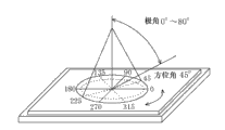
图16是对测定光扩散照度时的方位角及极角进行说明的示意图。FIG. 16 is a schematic diagram illustrating an azimuth angle and a polar angle when measuring light diffusion illuminance.
图17A是对于实施例1的光扩散元件用于说明基质与光扩散性微粒的界面附近的超微粒成分的分散浓度(存在比率)的算出方法的图。17A is a diagram for explaining a calculation method of the dispersion concentration (existence ratio) of the ultrafine particle component in the vicinity of the interface between the matrix and the light diffusing fine particles in the light diffusing element of Example 1. FIG.
图17B是对于实施例1的光扩散元件表示距光扩散性微粒表面的距离与超微粒成分的分散浓度(存在比率)的关系的曲线图。17B is a graph showing the relationship between the distance from the surface of light-diffusing fine particles and the dispersion concentration (existence ratio) of ultrafine-particle components for the light-diffusing element of Example 1. FIG.
图18(a)~(c)是表示基质的平均折射率及光扩散性微粒的折射率、与后向散射的关系的模拟曲线图。18( a ) to ( c ) are simulation graphs showing the relationship between the average refractive index of the matrix and the refractive index of light-diffusing fine particles, and backscattering.
图19(a)~(b)是表示基质的平均折射率及光扩散性微粒的折射率、与扩散性及后向散射的关系的模拟曲线图。19( a ) to ( b ) are simulation graphs showing the relationship between the average refractive index of the matrix and the refractive index of light-diffusing fine particles, and diffusivity and backscattering.
图20(a)~(b)是表示基质的平均折射率及光扩散性微粒的折射率、与扩散性及后向散射的关系的模拟曲线图。20( a ) to ( b ) are simulation graphs showing the relationship between the average refractive index of the matrix and the refractive index of light-diffusing fine particles, and diffusivity and backscattering.
图21(a)~(b)是表示基质的平均折射率及光扩散性微粒的折射率、与扩散性及后向散射的关系的模拟曲线图。21( a ) to ( b ) are simulation graphs showing the relationship between the average refractive index of the matrix and the refractive index of light-diffusing fine particles, and diffusivity and backscattering.
图22是表示Δn/L与扩散性的关系的模拟曲线图。Fig. 22 is a simulation graph showing the relationship between Δn/L and diffusivity.
图23是表示一般的直下型背光单元的基本结构的概略剖面图。23 is a schematic cross-sectional view showing the basic structure of a general direct-type backlight unit.
具体实施方式Detailed ways
以下,一面参照附图一面对本发明的优选实施方式进行说明,但本发明并不限于这些具体实施方式。Hereinafter, preferred embodiments of the present invention will be described with reference to the drawings, but the present invention is not limited to these specific embodiments.
A.光扩散元件A. Light Diffusion Element
A-1.整体构成A-1. Overall composition
本发明的光扩散元件,具有:具有第1折射率n1的第1区域及具有第2折射率n2的第2区域。本发明的光扩散元件,是通过第1区域与第2区域的折射率差来表现光扩散功能。在本发明中,第1区域由实质上为球壳状的折射率调制区域包围,第2区域以位于折射率调制区域的与第1区域相反侧的方式构成。因此,在本发明的光扩散元件中,外观上成为由折射率调制区域包围的第1区域分散在第2区域中的状态。在折射率调制区域中,折射率实质上连续变化。在本说明书中,所谓“折射率实质上连续变化”是指折射率调制区域中折射率实质上连续变化即可。因此,即便在例如第1区域与折射率调制区域的界面及/或折射率调制区域与第2区域的界面上存在规定范围内(例如,折射率差为0.05以下)的折射率间隙(refractive index gap),该间隙也可以被允许。The light diffusion element of the present invention has a first region having a first refractive index n1 and a second region having a second refractive index n2. The light-diffusing element of the present invention expresses a light-diffusing function by a difference in refractive index between the first region and the second region. In the present invention, the first region is surrounded by a substantially spherical refractive index modulation region, and the second region is configured to be located on the opposite side of the refractive index modulation region from the first region. Therefore, in the light-diffusing element of the present invention, the first regions surrounded by the refractive index modulation regions appear to be dispersed in the second regions. In the refractive index modulated region, the refractive index varies substantially continuously. In the present specification, "the refractive index changes substantially continuously" means that the refractive index may change substantially continuously in the refractive index modulation region. Therefore, even if there is a refractive index gap (refractive index gap) within a predetermined range (for example, the refractive index difference is 0.05 or less) on the interface between the first region and the refractive index modulation region and/or the interface between the refractive index modulation region and the second region. gap), the gap can also be allowed.
在本发明中,光扩散元件满足下述式(1)及(2):In the present invention, the light diffusion element satisfies the following formulas (1) and (2):
0.0006≤Δn/L···(1)0.0006≤Δn/L···(1)
10≤(Δn)2×A×B≤100···(2)10≤(Δn) 2 ×A×B≤100···(2)
在这里,Δn是第1折射率n1与第2折射率n2之差的绝对值|n1-n2|,L(nm)是折射率调制区域的平均厚度,Δn/L的单位是(nm-1),A是将整个光扩散元件设为100重量份时的构成第1区域的材料的重量份数,B是将整个光扩散元件设为100重量份时的构成第2区域的材料的重量份数。根据本发明,以满足式(1)及(2)的方式使得第1区域及第2区域以及折射率调制区域最佳化,由此可获得可实现低后向散射且高浊度的薄膜的光扩散元件。更具体而言,将Δn/L设为规定值以上(形成折射率变化陡峭的折射率调制区域)而缩小折射率调制区域所占的空间,由此提高第1区域的存在比率,由此提高散射效率,即便是薄膜,也可实现较高的浊度(优异的光扩散性)。进而,通过与利用折射率调制区域的后向散射的抑制的协同效果,可获得可实现低后向散射且高浊度的薄膜的光扩散元件。Here, Δn is the absolute value |n1-n2| of the difference between the first refractive index n1 and the second refractive index n2, L (nm) is the average thickness of the refractive index modulation region, and the unit of Δn/L is (nm -1 ), A is the parts by weight of the material constituting the first region when the whole light diffusing element is set as 100 parts by weight, and B is the parts by weight of the material constituting the second region when the whole light diffusing element is set as 100 parts by weight number. According to the present invention, by optimizing the first region, the second region, and the refractive index modulation region so as to satisfy the formulas (1) and (2), it is possible to obtain a film capable of achieving low backscattering and high haze. light diffusing element. More specifically, the space occupied by the refractive index modulation region is reduced by setting Δn/L to a predetermined value or more (forming a refractive index modulation region with a steep refractive index change), thereby increasing the ratio of the first region, thereby improving Scattering efficiency, high haze (excellent light diffusivity) can be achieved even in thin films. Furthermore, the synergistic effect with the suppression of backscattering by the refractive index modulation area|region can obtain the light-diffusion element which can realize the thin film of low backscattering and high haze.
Δn优选为0.08以上,更优选为0.10以上。Δn的上限例如为0.30。若Δn低于0.08,则大多数情况下无法获得充分大的(Δn)2×A×B,因此无法获得薄膜状且具有较强的光扩散性的光扩散元件(例如,浊度成为90%以下),其结果,在组装到液晶显示装置的情形时无法使来自光源的光充分地扩散,故而有视角变窄的可能。若Δn超过0.30,则即便形成有折射率调制区域,也无法充分抑制后向散射,故而有后向散射增大的可能。另外,有时构成第1区域及第2区域的材料选定变得困难。可实现这样的Δn/L的折射率调制区域的平均厚度L优选为5nm~500nm,更优选为12nm~400nm,进而优选为15nm~300nm。若平均厚度L低于5nm,则有时后向散射增大。若平均厚度L超过500nm,则第1区域或第2区域减少,结果无法获得充分的(Δn)2×A×B,故而有时无法获得薄膜状且具有较强的光扩散性的光扩散元件。Δn is preferably 0.08 or more, more preferably 0.10 or more. The upper limit of Δn is, for example, 0.30. If Δn is less than 0.08, a sufficiently large (Δn) 2 ×A×B cannot be obtained in many cases, so a film-shaped light-diffusing element with strong light-diffusing properties (for example, a haze of 90% hereinafter), as a result, the light from the light source cannot be sufficiently diffused when incorporated into a liquid crystal display device, and thus the viewing angle may be narrowed. If Δn exceeds 0.30, even if the refractive index modulation region is formed, backscattering cannot be sufficiently suppressed, so backscattering may increase. In addition, it may become difficult to select materials constituting the first region and the second region. The average thickness L of the refractive index modulation region capable of realizing such Δn/L is preferably 5 nm to 500 nm, more preferably 12 nm to 400 nm, and still more preferably 15 nm to 300 nm. When the average thickness L is less than 5 nm, backscattering may increase. When the average thickness L exceeds 500 nm, the first region or the second region decreases, and as a result, sufficient (Δn) 2 ×A×B cannot be obtained. Therefore, a thin-film light-diffusing element having strong light-diffusing properties may not be obtained.
Δn/L优选为0.0006~0.01。在Δn/L低于0.0006的情形时,Δn低于0.08或者L超过500nm的情形较多,因此后向散射增大,或者无法获得薄膜状且具有较强的光扩散性的光扩散元件的情形较多。若Δn/L超过0.01,则有时折射率调制区域中难以使折射率实质上连续变化。Δn/L is preferably 0.0006 to 0.01. When Δn/L is less than 0.0006, Δn is less than 0.08 or L exceeds 500nm in many cases, so backscattering increases, or it is not possible to obtain a film-shaped light-diffusing element with strong light-diffusing properties. more. When Δn/L exceeds 0.01, it may be difficult to change the refractive index substantially continuously in the refractive index modulation region.
如式(2)所表示,(Δn)2×A×B为10~100,优选为20~50。若(Δn)2×A×B低于10,则无法获得薄膜状且具有较强的光扩散性的光扩散元件的情形较多。在(Δn)2×A×B超过100的情形时,Δn超过0.3的情形较多,结果有时无法有效抑制后向散射。以下对使(Δn)2×A×B的值在式(2)的范围内最佳化的技术含义进行说明。在本发明的光扩散元件中,光扩散性微粒的优选直径如下所述为1μm~10μm。已知在这样的粒径范围内引起的光散射是Mie散射的区域,在Mie散射的区域中,光扩散强度与Δn的平方成比例。另一方面,不限于光,若根据一般电磁波的散射理论,则体积分率φ的电子密度(在光的情形时为折射率)的波动存在于基质内时的物体散射强度与φ×(1-φ)成比例。其原因在于:若φ超过50%,则基质成分成为少数成分,基质反转成散射成分。同样,若将具有第1折射率的材料(构成第1区域的材料)的重量份数设为A,将具有第2折射率的材料(构成第2区域的材料)的重量份数设为B,则光扩散强度与A×B成比例。即,必须是不仅使充分量的第1区域(例如,光扩散性微粒)存在于第2区域(例如,基质)中,而且要在该第1区域的周围存在充分量的第2区域。在这里,在从第1折射率变成第2折射率的折射率调制区域存在于第1区域与第2区域的边界的情形时,该折射率调制区域发挥出抑制后向散射的作用,另一方面,无助于光扩散强度。即,若该折射率调制区域(即,既非A也非B的区域)大量存在于光扩散元件中,则第1区域或第2区域减少,因此即便可抑制后向散射,也难以获得既薄且具有较强光扩散性的光扩散元件。根据本发明,以满足式(1)的方式使得Δn/L最佳化,且以满足式(2)的方式使得(Δn)2×A×B最佳化,由此可获得具有较强的光扩散性(较高的浊度)且后向散射较少的薄膜的光扩散元件。As represented by formula (2), (Δn) 2 ×A×B is 10-100, preferably 20-50. When (Δn) 2 ×A×B is less than 10, a film-form light-diffusing element having strong light-diffusing properties may not be obtained in many cases. When (Δn) 2 ×A×B exceeds 100, Δn exceeds 0.3 in many cases, and as a result, backscattering may not be effectively suppressed. The technical meaning of optimizing the value of (Δn) 2 ×A×B within the range of the formula (2) will be described below. In the light-diffusing element of the present invention, the preferable diameter of the light-diffusing fine particles is 1 μm to 10 μm as described below. It is known that light scattering caused in such a particle size range is a region of Mie scattering, and in the region of Mie scattering, the light diffusion intensity is proportional to the square of Δn. On the other hand, not limited to light, according to the scattering theory of general electromagnetic waves, the object scattering intensity when fluctuations in the electron density (refractive index in the case of light) of the volume fraction φ exists in the matrix is the same as φ×(1 -φ) proportional to. The reason for this is that when φ exceeds 50%, the matrix component becomes a minority component, and the matrix is reversed to become a scattering component. Similarly, if the parts by weight of the material with the first refractive index (the material constituting the first region) is set as A, the parts by weight of the material with the second refractive index (the material constituting the second region) is set as B , then the light diffusion intensity is proportional to A×B. That is, not only a sufficient amount of the first region (for example, light-diffusing fine particles) exists in the second region (for example, the matrix), but also a sufficient amount of the second region exists around the first region. Here, when the refractive index modulation region that changes from the first refractive index to the second refractive index exists at the boundary between the first region and the second region, the refractive index modulation region plays a role of suppressing backscattering. On the one hand, it does not contribute to the intensity of light diffusion. That is, if the refractive index modulation region (that is, a region that is neither A nor B) exists in a large number in the light diffusing element, the first region or the second region will decrease, so even if backscattering can be suppressed, it is difficult to obtain both. Thin light diffusing element with strong light diffusing properties. According to the present invention, Δn/L is optimized in a manner satisfying formula (1), and (Δn) 2 ×A×B is optimized in a manner satisfying formula (2), thereby obtaining a strong A light diffusing element of a light diffusive (higher haze) film with less backscattering.
将整个光扩散元件设为100重量份时的构成第1区域的材料的重量份数A优选为10重量份~60重量份,更优选为15重量份~50重量份。将整个光扩散元件设为100重量份时的构成第2区域的材料的重量份数B优选为40重量份~90重量份,更优选为50重量份~85重量份。在重量份数A或B偏离这样的优选范围的情形时,无法获得充分大的Δn2×A×B,故而有无法获得薄膜状且具有较强的光扩散性的光扩散元件的可能。进而,在重量份数A超过60重量份或者重量份数B低于40重量份的情形时,光扩散性微粒的形状会引起光扩散元件的表面形成凹凸,故而有从光扩散元件的表面产生较强的后向散射的可能。根据本发明,因存在于第1区域(例如光扩散性微粒)与第2区域(例如基质)之间的折射率调制区域的折射率梯度十分陡峭,故而折射率调制区域在光扩散元件中所占的比例较少即可,因此可确保尽管薄膜但足以获得较强的光扩散性的第1区域及第2区域。本发明的光扩散元件中折射率调制区域所占的重量份数C,在将整个光扩散元件设为100重量份时,优选为1重量份~20重量份,更优选为1重量份~5重量份。进而,重量份数C相对于重量份数A的比例(C/A)优选为5%~100%。It is preferable that the weight part A of the material which comprises a 1st area|region is 10 weight part - 60 weight part when the whole light-diffusion element is 100 weight part, and it is more preferable that it is 15 weight part - 50 weight part. As for the weight part B of the material which comprises a 2nd area|region when the whole light-diffusion element is 100 weight part, Preferably it is 40 weight part - 90 weight part, More preferably, it is 50 weight part - 85 weight part. When the parts by weight A or B deviate from such a preferable range, sufficiently large Δn 2 ×A×B cannot be obtained, and thus a film-like light diffusing element having strong light diffusing properties may not be obtained. Furthermore, when the parts by weight A exceeds 60 parts by weight or the parts by weight B is lower than 40 parts by weight, the shape of the light-diffusing fine particles will cause the surface of the light-diffusing element to form unevenness, so there will be a problem from the surface of the light-diffusing element. Strong backscattering possible. According to the present invention, since the refractive index gradient of the refractive index modulation region existing between the first region (for example, light-diffusing fine particles) and the second region (for example, the matrix) is very steep, the refractive index modulation region is defined in the light diffusing element. Since the proportion is only small, it is possible to secure the first region and the second region that are sufficiently strong to obtain light diffusivity in spite of being a thin film. The number of parts by weight C of the refractive index modulation region in the light diffusion element of the present invention is preferably 1 to 20 parts by weight, more preferably 1 to 5 parts by weight when the entire light diffusion element is set to 100 parts by weight. parts by weight. Furthermore, the ratio (C/A) of parts by weight C to parts by weight A is preferably 5% to 100%.
第1区域、第2区域及折射率调制区域是可通过任意适当的方法而形成。例如可列举如下所述的方法:(1)将折射率从微粒的中心部朝向外侧连续变化的所谓GRIN微粒等折射率倾斜微粒分散在树脂中,而将折射率倾斜部分用作折射率调制区域;(2)基质中使用树脂成分与超微粒成分,通过超微粒成分的分散浓度的实质性梯度而在基质与光扩散性微粒的界面或其附近形成折射率调制区域。以下,主要对基质中使用树脂成分与超微粒成分的实施方式进行说明,关于使用折射率倾斜微粒的实施方式,仅对其特征部分进行简单说明。The first region, the second region, and the refractive index modulation region can be formed by any appropriate method. For example, the following method can be mentioned: (1) The refractive index gradient particles such as so-called GRIN particles whose refractive index continuously changes from the center of the particle toward the outside are dispersed in a resin, and the refractive index gradient portion is used as a refractive index modulation region. (2) Using the resin component and the ultrafine particle component in the matrix, the refractive index modulation region is formed at the interface between the matrix and the light-diffusing fine particle or its vicinity through the substantial gradient of the dispersion concentration of the ultrafine particle component. Hereinafter, the embodiment in which the resin component and the ultrafine particle component are used in the matrix will be mainly described, and only the characteristic parts will be briefly described in the embodiment in which the refractive index gradient particle is used.
在一个实施方式中,本发明的光扩散元件具有基质及分散在该基质中的光扩散性微粒,在该光扩散性微粒的表面附近外部,形成有折射率实质上连续变化的折射率调制区域。即,光扩散性微粒对应于第1区域,基质对应于第2区域。本实施方式的光扩散元件,通过基质与光扩散性微粒的折射率差来表现光扩散功能。如上所述,在光扩散性微粒的表面附近外部形成有折射率调制区域,因此基质具有该光扩散性微粒的表面附近外部的折射率调制区域及该折射率调制区域的外侧(远离光扩散性微粒的一侧)的折射率恒定区域。优选基质中的除折射率调制区域以外的部分实质上为折射率恒定区域。如上所述,在本说明书中,所谓“折射率实质上连续变化”是指折射率调制区域中折射率至少从光扩散性微粒表面至折射率恒定区域实质上连续变化即可。因此,例如在光扩散性微粒与折射率调制区域的界面、及/或折射率调制区域与折射率恒定区域的界面上,即便存在规定范围内(例如,折射率差为0.05以下)的折射率间隙,该间隙也可以被允许。In one embodiment, the light-diffusing element of the present invention has a matrix and light-diffusing fine particles dispersed in the matrix, and a refractive-index modulation region in which the refractive index changes substantially continuously is formed outside the vicinity of the surface of the light-diffusing fine particles. . That is, the light-diffusing fine particles correspond to the first region, and the matrix corresponds to the second region. The light-diffusing element of this embodiment expresses a light-diffusing function by the difference in refractive index between the matrix and the light-diffusing fine particles. As described above, the refractive index modulation region is formed outside the vicinity of the surface of the light diffusing fine particles, so the matrix has the refractive index modulation region outside the vicinity of the surface of the light diffusing fine particles and the outer side of the refractive index modulation region (away from the light diffusing property). One side of the particle) constant refractive index region. It is preferable that the portion of the matrix other than the refractive index modulation region is substantially a constant refractive index region. As mentioned above, in this specification, "refractive index changes substantially continuously" means that in the refractive index modulation region, the refractive index may change substantially continuously at least from the surface of the light-diffusing fine particle to the constant refractive index region. Therefore, for example, at the interface between the light-diffusing fine particles and the refractive index modulation region, and/or the interface between the refractive index modulation region and the refractive index constant region, even if there is a refractive index within a predetermined range (for example, the difference in refractive index is 0.05 or less). gap, which can also be allowed.
在本实施方式中,上述式(1)及(2)中的Δn是基质的平均折射率nM与光扩散性微粒的折射率nP之差的绝对值|nM-nP|,L(nm)是折射率调制区域的平均厚度,Δn/L的单位是(nm-1),A是将整个光扩散元件设为100重量份时的光扩散性微粒的重量份数,B是将整个光扩散元件设为100重量份时的基质的重量份数。优选为nM>nP。需要说明的是,在本实施方式中,仅在涉及式(2)的情形时,基质是指从光扩散元件去除光扩散性微粒及折射率调制区域的部分(即,折射率恒定区域)。In the present embodiment, Δn in the above formulas (1) and (2) is the absolute value of the difference between the average refractive index n M of the matrix and the refractive index n P of the light-diffusing fine particles |n M −n P |, L (nm) is the average thickness of the refractive index modulation region, the unit of Δn/L is (nm −1 ), A is the number of parts by weight of light-diffusing fine particles when the entire light-diffusing element is taken as 100 parts by weight, and B is the number of parts by weight of The whole light-diffusing element is set as the weight part of the matrix when 100 weight part. Preferably n M >n P . In this embodiment, only in the case of formula (2), the matrix refers to a portion (that is, a constant refractive index region) from the light diffusing element except the light diffusing fine particles and the refractive index modulation region.
图1A是本实施方式的光扩散元件的概略剖面图,图1B是将图1A的光扩散元件中的光扩散微粒附近放大进行说明的示意图。基质优选包含树脂成分及超微粒成分。图1A的光扩散元件100具有:包含树脂成分11及超微粒成分12的基质10、以及分散在基质10中的光扩散性微粒20。图1A中,在光扩散性微粒20的表面附近外部形成有折射率调制区域30。在折射率调制区域30中,如上所述折射率实质上连续变化。FIG. 1A is a schematic cross-sectional view of a light-diffusing element according to this embodiment, and FIG. 1B is a schematic diagram illustrating the vicinity of light-diffusing fine particles in the light-diffusing element of FIG. 1A in an enlarged manner. The matrix preferably contains a resin component and an ultrafine particle component. The
优选在折射率调制区域30中,除了折射率实质上连续变化之外,上述折射率调制区域的最外部的折射率与上述折射率恒定区域的折射率实质上相同。换言之,在本实施方式的光扩散元件中,折射率从折射率调制区域向折射率恒定区域连续地变化,优选折射率从光扩散性微粒向折射率恒定区域连续地变化(图2)。优选该折射率变化系如图2所示般平稳。即,在折射率调制区域与折射率恒定区域的边界,以能在折射率变化曲线上引出切线的形状产生变化。优选在折射率调制区域中,折射率变化的梯度会随着远离上述光扩散性微粒而变大。根据本实施方式,如后所述适当地选择光扩散性微粒、基质的树脂成分及超微粒成分,由此可实现实质上连续的折射率变化。如上所述实现陡峭(Δn/L非常大)且这样的实质上连续的折射率变化的情况是本发明的特征之一。其结果,即便增大基质10(实质上为折射率恒定区域)与光扩散性微粒20的折射率差,也可抑制基质10与光扩散性微粒20的界面的反射,故而可抑制后向散射。进而,在折射率恒定区域中,折射率与光扩散性微粒20有较大不同的超微粒成分12的重量浓度相对升高,因此可增大基质10(实质上为折射率恒定区域)与光扩散性微粒20的折射率差。此外,在本实施方式的光扩散元件中,通过满足上述式(1),可增加微粒的存在比率,提高散射效率。其结果,即便是薄膜,也可实现较高的浊度(较强的扩散性)。因此,根据本实施方式的光扩散元件,尽管是薄膜,也可增大折射率差而实现高浊度,且可显著抑制后向散射。这样的特征特别适用于如准直背光前扩散系统中所使用的光扩散元件那样要求较强的扩散性(浊度为90%以上)的用途。另一方面,根据未形成折射率调制区域的以往的光扩散元件,若想要通过增大折射率差来赋予较强的扩散性(高浊度值),则无法消除界面上的折射率的间隙。其结果,会导致在光扩散性微粒与基质的界面上的反射所引起的后向散射增大,因此在外光存在下黑显示不会充分变黑(导致所谓浮黑)的情形较多。根据本发明,形成满足上述式(1)及(2)且折射率实质上连续变化的折射率调制区域,由此解决上述以往技术的问题,可获得浊度值较高、具有较强的扩散性且后向散射受到抑制的薄膜的光扩散元件。Preferably, in the refractive
优选上述光扩散元件100满足式(3):Preferably, the above-mentioned
0.005≤L/rP≤0.40···(3)0.005≤L/ rP ≤0.40···(3)
在这里,rP是上述光扩散性微粒的半径(nm)。L/rP更优选为0.02~0.15。在L/rP低于0.005的情形时,不会形成充分厚度的折射率调制区域,因此无法良好地抑制后向散射的情形较多。在L/rP超过0.40的情形时,无法获得充分大的Δn2×A×B的情形较多,而且由于Δn/L减小,而有时无法获得薄膜状且具有较强的光扩散性的光扩散元件。根据本发明,如上所述可使折射率调制区域的平均厚度L变得非常薄,因此可使L/rP变得非常小。其结果,可充分维持上述光扩散性微粒的散射能力,并且可良好地抑制后向散射。因此,即便是薄膜,也可实现较高的浊度(较强的扩散性)。Here, r P is the radius (nm) of the light-diffusing fine particles. L/r P is more preferably 0.02 to 0.15. When L/r P is less than 0.005, a sufficiently thick refractive index modulation region cannot be formed, and thus backscattering cannot be well suppressed in many cases. When L/r P exceeds 0.40, it is often impossible to obtain a sufficiently large Δn 2 ×A×B, and since Δn/L decreases, it may not be possible to obtain a thin film with strong light diffusing properties. light diffusing element. According to the present invention, the average thickness L of the refractive index modulation region can be made very thin as described above, and thus L/r P can be made very small. As a result, the scattering ability of the light-diffusing fine particles can be sufficiently maintained, and backscattering can be favorably suppressed. Therefore, even a thin film can achieve high haze (strong diffusivity).
上述折射率调制区域30的厚度(从折射率调制区域最内部至折射率调制区域最外部的距离)也可恒定(即,折射率调制区域也可在光扩散性微粒的周围成同心球状扩展),厚度也可因光扩散性微粒表面的位置而不同(例如,也可如金米糖的轮廓形状)。优选折射率调制区域30的厚度因光扩散性微粒表面的位置而不同。若为这样的构成,则折射率调制区域30中可使折射率更平稳地连续变化。上述平均厚度L是折射率调制区域30的厚度因光扩散性微粒表面的位置而不同时的平均厚度,在厚度恒定的情形时,是指其厚度。The thickness of the above-mentioned refractive index modulation region 30 (the distance from the innermost portion of the refractive index modulation region to the outermost portion of the refractive index modulation region) may also be constant (that is, the refractive index modulation region may also expand concentrically around the light-diffusing fine particles) , the thickness may also vary depending on the position of the surface of the light-diffusing fine particle (for example, it may also be like the contour shape of golden rice candy). It is preferable that the thickness of the refractive
如上所述,基质10优选包含树脂成分11及超微粒成分12。优选上述折射率调制区域30基于基质10中的超微粒成分12的分散浓度的实质性梯度而形成。具体而言,在折射率调制区域30中,随着远离光扩散性微粒20,超微粒成分12的分散浓度(具有代表性的是由重量浓度加以规定)升高(树脂成分11的重量浓度必然降低)。换言之,在折射率调制区域30中的最接近光扩散性微粒20的区域,超微粒成分12以相对低浓度分散,随着远离光扩散性微粒20,超微粒成分12的浓度增大。例如,基于透过型电子显微镜(TEM,Transmission Electron Microscopy)图像的基质10中的超微粒成分12的面积比率,在接近光扩散性微粒20的一侧较小并在接近基质10的一侧较大,关于该面积比率,一面从光扩散性微粒侧向基质侧(折射率恒定区域侧)形成实质性梯度一面产生变化。将表示其代表性分散状态的TEM图像示于图3。在本说明书中,所谓“基于透过型电子显微镜图像的基质中的超微粒成分的面积比率”,是指在包含光扩散性微粒的直径的剖面的透过型电子显微镜图像中,规定范围(规定面积)的基质中超微粒成分的面积所占的的比率。该面积比率对应于超微粒成分的三维分散浓度(实际分散浓度)。例如,若为如上所述的面积比率,则关于超微粒成分12的分散浓度,其浓度变化的梯度在接近光扩散性微粒20的一侧较小,并在接近折射率恒定区域的一侧较大,一面从光扩散微粒侧向折射率恒定区域侧形成实质性梯度一面产生变化。换言之,超微粒成分12的分散浓度,其浓度变化的梯度会随着远离光扩散性微粒而变大。该超微粒成分的面积比率可通过任意适当的图像解析软件而求出。需要说明的是,上述面积比率具有代表性的是对应于超微粒成分的各粒子间的平均最短距离。具体而言,超微粒成分的各粒子间的平均最短距离在折射率调制区域中随着远离光扩散性微粒而缩短,在折射率恒定区域中变得恒定(例如,平均最短距离在光扩散性微粒的最接近区域中为3nm~100nm左右,在折射率恒定区域中为1nm~20nm)。平均最短距离是将如图3那样的分散状态的TEM图像进行二值化,例如可利用图像解析软件“A像くん”(旭化成Engineering公司制造)的重心间距离法算出。如上所述,根据本实施方式,可利用超微粒成分12的分散浓度的实质性梯度而在基质与光扩散性微粒的界面附近形成折射率调制区域30,因此可以以简单的工序且以低成本制造光扩散元件。进而,利用超微粒成分的分散浓度的实质性梯度而形成折射率调制区域,由此可使折射率在折射率调制区域30与折射率恒定区域的边界平稳地变化。进而,通过使用折射率与树脂成分及光扩散性微粒有较大不同的超微粒成分,可增大光扩散性微粒与基质(实质上为折射率恒定区域)的折射率差,且使折射率调制区域的折射率梯度陡峭。As described above, the
上述折射率调制区域(实质上是如上所述的超微粒成分的分散浓度的实质性梯度),可通过适当地选择基质的树脂成分及超微粒成分以及光扩散性微粒的构成材料、以及化学特性及热力学特性而形成。例如,由同系材料(例如有机化合物彼此)构成树脂成分及光扩散性微粒,由与树脂成分及光扩散性微粒不同系的材料(例如无机化合物)构成超微粒成分,由此可良好地形成折射率调制区域。进而优选例如由同系材料中相溶性较高的材料彼此构成树脂成分及光扩散性微粒。折射率调制区域的厚度及折射率梯度,可通过调整基质的树脂成分及超微粒成分以及光扩散性微粒的化学特性及热力学特性来加以控制。需要说明的是,在本说明书中,所谓“同系”是指化学结构或特性同等或类似,所谓“不同系”是除外同系。是否同系是可根据基准选择方法而不同。例如,在以有机或无机为基准的情形时,有机化合物彼此为同系的化合物,有机化合物与无机化合物是不同系的化合物。在以聚合物的重复单元为基准的情形时,例如丙烯酸系聚合物与环氧系聚合物尽管彼此是有机化合物,但仍为不同系的化合物,在以周期表为基准的情形时,碱金属与过渡金属尽管彼此是无机元素,但仍为不同系的元素。The above-mentioned refractive index modulation region (essentially the substantial gradient of the dispersion concentration of the ultrafine particle component as described above) can be obtained by appropriately selecting the constituent materials and chemical properties of the resin component of the matrix, the ultrafine particle component, and the light diffusing fine particles. and thermodynamic properties. For example, the resin component and light-diffusing fine particles are composed of homogeneous materials (such as organic compounds), and the ultra-fine particle components are composed of materials (such as inorganic compounds) that are different from the resin component and light-diffusing fine particles, thereby forming a good refraction. rate modulation area. Furthermore, it is preferable that the resin component and light-diffusing microparticles|fine-particles are comprised from materials with high compatibility among homogeneous materials, for example. The thickness and refractive index gradient of the refractive index modulation region can be controlled by adjusting the chemical and thermodynamic properties of the resin component and ultrafine particle component of the matrix, and the light diffusing fine particles. It should be noted that, in this specification, the so-called "homologous" refers to the same or similar chemical structures or properties, and the so-called "different system" excludes homologous. Whether or not it is homologous may vary depending on the benchmark selection method. For example, when referring to organic or inorganic compounds, organic compounds are compounds of the same series, and organic compounds and inorganic compounds are compounds of different series. In the case of repeating units of polymers, for example, acrylic polymers and epoxy polymers are different series of compounds although they are organic compounds. When based on the periodic table, alkali metal Although transition metals and transition metals are inorganic elements, they are still different elements.
更具体而言,如上所述的超微粒成分的分散浓度的实质性梯度,可通过以下(1)~(2)或它们的适当组合来实现:(1)调整基质中的超微粒成分的分散浓度。例如,通过增大超微粒成分的分散浓度,使得超微粒成分彼此的电性排斥增加,结果直至光扩散微粒附近都有超微粒成分存在,故而可在折射率调制区域中形成陡峭的折射率梯度(折射率调制区域的厚度减小)。(2)调整光扩散性微粒的交联度。例如,在交联度低的光扩散性微粒中,由于微粒表面的构成聚合物分子的自由度提高,因此超微粒成分难以靠近。其结果,可在折射率调制区域中形成平缓的折射率梯度(折射率调制区域的厚度增加)。优选通过适当地组合上述(1)与(2),而可实现如上所述的超微粒成分的分散浓度的实质性梯度。例如,使用氧化锆的超微粒成分与PMMA(polymethylmethacrylate,聚甲基丙烯酸甲酯)的光扩散性微粒,将该超微粒成分的分散浓度相对于基质100重量份设定为30重量份~70重量份,且使用相对于后述树脂成分前体的溶胀度(swellingdegree)为100%~200%的光扩散性微粒,由此可实现如下的分散浓度梯度:基质10中的超微粒成分12的分散浓度在接近光扩散性微粒20的一侧较小且在接近折射率恒定区域的一侧较大,并一面从光扩散微粒侧向折射率恒定区域侧形成实质性梯度一面产生变化。进而,可形成厚度因光扩散性微粒表面的位置而不同(例如,如金米糖的轮廓形状之类)的折射率调制区域。在这里,所谓“溶胀度”是指溶胀状态的粒子的平均粒径相对于溶胀前的粒子的平均粒径的比率。More specifically, the substantial gradient of the dispersion concentration of the ultrafine particle components as described above can be realized by the following (1) to (2) or their appropriate combination: (1) adjusting the dispersion of the ultrafine particle components in the matrix concentration. For example, by increasing the dispersion concentration of the ultrafine particle components, the electrical repulsion between the ultrafine particle components increases, and as a result, the ultrafine particle components exist up to the vicinity of the light-diffusing particles, so a steep refractive index gradient can be formed in the refractive index modulation region. (reduced thickness of the refractive index modulated region). (2) Adjusting the degree of crosslinking of the light-diffusing fine particles. For example, in light-diffusing fine particles with a low degree of crosslinking, since the degree of freedom of polymer molecules constituting the fine particle surface increases, ultrafine particle components are less likely to approach. As a result, a gentle refractive index gradient can be formed in the refractive index modulation region (thickness of the refractive index modulation region increases). Preferably, a substantial gradient in the dispersion concentration of the ultrafine particle component as described above can be realized by appropriately combining the above-mentioned (1) and (2). For example, using an ultrafine particle component of zirconia and light-diffusing fine particles of PMMA (polymethylmethacrylate), the dispersion concentration of the ultrafine particle component is set to 30 parts by weight to 70 parts by weight relative to 100 parts by weight of the matrix. parts, and use light-diffusing microparticles with a swelling degree (swellingdegree) of 100% to 200% relative to the resin component precursor described later, so that the following dispersion concentration gradient can be realized: the dispersion of the
如上所述,在本实施方式的光扩散元件100中,优选nM>nP。如在图4(a)及图4(b)中加以比较所示,在nM>nP的情形时,与nM<nP的情形相比,即便折射率调制区域的折射率梯度陡峭,也可更良好地抑制后向散射。As described above, in the
本发明的光扩散元件的光扩散特性,具有代表性的是由浊度及光扩散半值角来表示。所谓浊度表示光的扩散强度,即入射光的扩散程度。另一方面,所谓光扩散半值角表示扩散光的品质(quality),即所扩散的光的角度范围。本发明的光扩散元件在浊度较高的情形时充分发挥其效果。光扩散元件的浊度优选为90%以上,更优选为90%~99.9%,进而优选为92%~99.9%,特别优选为95%~99.9%,尤其优选为96%~99.9%,最优选为97%~99.9%。通过浊度为90%以上,而可优选地用作准直背光前扩散系统中的前光扩散元件。另外,将光扩散元件用于背光侧的偏光元件的情形时,可良好地消除灯影等亮度不均。进而,将光扩散元件用于具有前基板(例如触控面板)的液晶显示装置的情形时,由于光扩散元件充分发挥作为屏幕的功能,因此可降低视差。尤其是,在使用平行光光源装置的液晶显示装置中,就可兼顾到正面对比率的提高及视差的降低的方面而言优选。根据本发明,可获得具有这样的非常高的浊度且后向散射受到抑制的光扩散元件。需要说明的是,所谓准直背光前扩散系统是指在液晶显示装置中,使用准直背光的光(向固定方向聚光的亮度半辐值窄(例如,3°~35°或者±1.5°~±17.5°的)背光的光),在上侧偏振板的视认侧设置有前光扩散元件的系统。浊度可依据JIS7136求出。The light diffusion characteristics of the light diffusion element of the present invention are typically represented by haze and light diffusion half value angle. The so-called turbidity represents the diffusion intensity of light, that is, the degree of diffusion of incident light. On the other hand, the half-value angle of light diffusion indicates the quality of diffused light, that is, the angle range of diffused light. The light-diffusing element of the present invention fully exhibits its effect when the turbidity is high. The haze of the light diffusing element is preferably 90% or more, more preferably 90% to 99.9%, even more preferably 92% to 99.9%, particularly preferably 95% to 99.9%, especially preferably 96% to 99.9%, most preferably 97% to 99.9%. With a haze of more than 90%, it can be preferably used as a front light diffuser element in a collimated backlight front diffuser system. Moreover, when a light-diffusion element is used for the polarizing element of a backlight side, brightness|luminance unevenness, such as a lamp shadow, can be eliminated favorably. Furthermore, when using a light-diffusion element for the liquid crystal display device which has a front board|substrate (for example, touch panel), since a light-diffusion element fully functions as a screen, parallax can be reduced. In particular, in a liquid crystal display device using a parallel light source device, it is preferable in terms of both an improvement in the front contrast ratio and a reduction in parallax. According to the present invention, a light-diffusing member having such a very high haze and suppressed backscattering can be obtained. It should be noted that the so-called collimated backlight front diffusion system refers to the use of collimated backlight light in a liquid crystal display device (to a fixed direction with a narrow brightness half-width (for example, 3° to 35° or ± 1.5°) ~ ± 17.5° (light of the backlight), a system in which a front light diffusion element is provided on the viewing side of the upper polarizing plate. Turbidity can be calculated|required based on JIS7136.
上述光扩散元件的光扩散特性,若由光扩散半值角来表示,则优选为10°~150°(单侧5°~75°),更优选为10°~100°(单侧5°~50°),进而优选为30°~80°(单侧15°~40°)。若光扩散半值角太小,则有时斜向的视角(例如白色亮度)变窄。若光扩散半值角太大,则有时后向散射增加。将光扩散元件用于背光侧的偏光元件的情形时,光扩散半值角优选为25°(单侧12.5°)以上,更优选为30°~140°(单侧15°~70°),进而优选为50°~120°(单侧25°~60°)。The light diffusion characteristics of the above-mentioned light diffusion element are preferably 10° to 150° (5° to 75° on one side), more preferably 10° to 100° (5° to 75° on one side), if expressed by the light diffusion half-value angle. ~50°), more preferably 30°~80° (15°~40° on one side). When the light diffusion half-value angle is too small, the oblique viewing angle (for example, white brightness) may become narrow. If the light diffusion half-value angle is too large, backscattering may increase. When the light diffusing element is used as the polarizing element on the backlight side, the half-value angle of light diffusing is preferably 25° (12.5° on one side) or more, more preferably 30° to 140° (15° to 70° on one side), More preferably, it is 50° to 120° (25° to 60° on one side).
光扩散元件是后向散射率越低越优选。具体而言,后向散射率优选为0.5%以下。需要说明的是,在将光扩散元件用于背光侧偏光元件的情形时,后向散射率为3%以下左右即可,更优选为2%以下。As for the light diffusing element, the lower the backscattering rate, the more preferable. Specifically, the backscattering rate is preferably 0.5% or less. In addition, when using a light-diffusion element as a backlight side polarizing element, the backscattering rate should just be about 3 % or less, More preferably, it is 2 % or less.
上述光扩散元件的厚度可根据目的或所需的扩散特性而适当地设定。具体而言,上述光扩散元件的厚度优选为3μm~50μm,更优选为4μm~50μm,进而更优选为4μm~30μm,特别优选为4μm~20μm。根据本发明,可获得尽管厚度如此非常薄但具有如上所述的非常高的浊度(优异的光扩散性)的光扩散元件。进而,若为这样的较薄的厚度,则即便弯曲也不会破裂,故而可以以卷筒状进行保管。此外,如下所述,本发明的光扩散元件可通过涂敷而形成,因此例如可利用所谓卷对卷连续进行光扩散元件的制造及向偏振板的贴合。因此,本发明的光扩散元件,光扩散元件本身的生产性非常优异,且与如偏振板之类的其他光学部件的贴合的制造效率也极高。需要说明的是,所谓卷对卷是指将长条状膜彼此一面由辊搬送,一面对齐其长度方向连续贴合的方法。The thickness of the above-mentioned light-diffusing member can be appropriately set according to the purpose or required diffusion characteristics. Specifically, the thickness of the light diffusing element is preferably 3 μm to 50 μm, more preferably 4 μm to 50 μm, still more preferably 4 μm to 30 μm, particularly preferably 4 μm to 20 μm. According to the present invention, it is possible to obtain a light-diffusing member having a very high haze (excellent light-diffusing property) as described above despite such an extremely thin thickness. Furthermore, if it is such a thinner thickness, since it will not break even if it bends, it can store in roll form. In addition, as described below, since the light diffusion element of the present invention can be formed by coating, for example, the production of the light diffusion element and the bonding to the polarizing plate can be performed continuously by so-called roll-to-roll. Therefore, in the light diffusion element of the present invention, the productivity of the light diffusion element itself is very excellent, and the production efficiency of lamination with other optical members such as polarizing plates is also extremely high. In addition, roll-to-roll refers to the method in which elongated films are conveyed by a roll, and the longitudinal direction is aligned and bonded together continuously.
上述光扩散元件优选用于液晶显示装置,尤其优选用于准直背光前扩散系统、具有前基板的液晶显示装置。光扩散元件也可单独作为膜状或板状部件提供,也可贴合于任意适当的基材或偏振板而作为复合部件提供。也可在光扩散元件上层叠有防反射层。另外,光扩散元件也可优选用于液晶显示装置的背光部。The above-mentioned light diffusing element is preferably used in a liquid crystal display device, especially preferably used in a collimated backlight front diffusion system and a liquid crystal display device with a front substrate. The light diffusing element may be provided alone as a film-shaped or plate-shaped member, or may be provided as a composite member bonded to any appropriate substrate or polarizing plate. An antireflection layer may be laminated on the light diffusion element. Moreover, a light-diffusion element can also be used suitably for the backlight part of a liquid crystal display device.
A-2.基质A-2. Matrix
如上所述,基质10优选包含树脂成分11及超微粒成分12。如上所述以及如图1A及图1B所示,超微粒成分12是以在基质10与光扩散性微粒20的界面附近形成折射率调制区域30的方式,分散在树脂成分11中。As described above, the
A-2-1.树脂成分A-2-1. Resin composition
树脂成分11是只要形成上述折射率调制区域,则可由任意适当的材料构成。优选如上所述,树脂成分11由与光扩散性微粒同系的化合物且与超微粒成分不同系的化合物构成。由此,可在基质与光扩散性微粒的界面附近(光扩散性微粒的表面附近)良好地形成折射率调制区域。进而优选树脂成分11由与光扩散性微粒同系的化合物中相溶性较高的化合物构成。由此,可形成具有所需的折射率梯度的折射率调制区域。更详细而言,树脂成分在光扩散性微粒的附近,相比于局部与超微粒成分均匀溶解或者分散的状态,反而仅由树脂成分包围光扩散性微粒时体系整体的能量更稳定的情形较多。其结果,树脂成分的重量浓度在光扩散性微粒的最接近区域高于整个基质中的树脂成分的平均重量浓度,随着远离光扩散性微粒而降低。因此,可在基质与光扩散性微粒的界面附近(光扩散性微粒的表面附近)良好地形成折射率调制区域。The
上述树脂成分优选由有机化合物构成,更优选由电离性射线固化型树脂构成。电离性射线固化型树脂由于涂膜的硬度优异,故而容易弥补作为后述超微粒成分的弱点的机械强度。另外,在将光扩散元件用于背光侧的偏光元件的情形时,可对所得的偏光元件赋予硬涂性。作为电离性射线,例如可列举紫外线、可见光、红外线、电子射线。优选为紫外线,因此树脂成分特别优选由紫外线固化型树脂构成。作为紫外线固化型树脂,例如可列举丙烯酸酯树脂(环氧丙烯酸酯、聚酯丙烯酸酯、丙烯酸丙烯酯、醚丙烯酸酯)等由自由基聚合型单体及/或寡聚物形成的树脂。构成丙烯酸酯树脂的单体成分(前体)的分子量优选为200~700。作为构成丙烯酸酯树脂的单体成分(前体)的具体例,可列举季戊四醇三丙烯酸酯(PETA:分子量298)、新戊二醇二丙烯酸酯(NPGDA:分子量212)、二季戊四醇六丙烯酸酯(DPHA:分子量632)、二季戊四醇五丙烯酸酯(DPPA:分子量578)、三羟甲基丙烷三丙烯酸酯(TMPTA:分子量296)。前体中也可根据需要添加引发剂。作为引发剂,例如可列举UV自由基产生剂(日本BASF公司制造的Irgacure907、Irgacure127、Irgacure192等)、过氧化苯甲酰。上述树脂成分,除了上述电离性射线固化型树脂以外,也可包含其他树脂成分。其他树脂成分可为电离性射线固化型树脂,也可为热固性树脂,还可为热塑性树脂。作为其他树脂成分的代表例,可列举脂肪族系(例如聚烯烃)树脂、聚氨酯系树脂。在用其他树脂成分的情形时,其种类或配合量被调整成良好地形成上述折射率调制区域。The above-mentioned resin component is preferably composed of an organic compound, more preferably an ionizing radiation-curable resin. Since the ionizing radiation-curable resin is excellent in the hardness of the coating film, it is easy to make up for the mechanical strength which is a weakness of the ultrafine particle component described later. Moreover, when using a light-diffusion element for the polarizing element on the backlight side, hard-coat property can be provided to the polarizing element obtained. Examples of ionizing rays include ultraviolet rays, visible light, infrared rays, and electron rays. Ultraviolet rays are preferred, and therefore the resin component is particularly preferably composed of ultraviolet curable resins. Examples of ultraviolet curable resins include resins made of radical polymerizable monomers and/or oligomers, such as acrylate resins (epoxy acrylate, polyester acrylate, acrylate acrylate, ether acrylate). It is preferable that the molecular weight of the monomer component (precursor) which comprises an acrylate resin is 200-700. Specific examples of the monomer component (precursor) constituting the acrylate resin include pentaerythritol triacrylate (PETA: molecular weight 298), neopentyl glycol diacrylate (NPGDA: molecular weight 212), dipentaerythritol hexaacrylate ( DPHA: molecular weight 632), dipentaerythritol pentaacrylate (DPPA: molecular weight 578), trimethylolpropane triacrylate (TMPTA: molecular weight 296). An initiator may also be added to the precursor as needed. Examples of the initiator include UV radical generators (Irgacure 907, Irgacure 127, Irgacure 192, etc. manufactured by BASF Japan), and benzoyl peroxide. The above-mentioned resin component may contain other resin components besides the above-mentioned ionizing radiation-curable resin. The other resin components may be ionizing radiation curable resins, thermosetting resins, or thermoplastic resins. Typical examples of other resin components include aliphatic (for example, polyolefin) resins and polyurethane resins. In the case of using other resin components, the type or compounding amount thereof is adjusted so that the above-mentioned refractive index modulation region is formed satisfactorily.
上述树脂成分具有代表性的是满足下述式(4):The above resin components typically satisfy the following formula (4):
|nP-nA|<|nP-nB|···(4)|n P -n A |<|n P -n B |···(4)
式(4)中,nA表示基质的树脂成分的折射率,nB表示基质的超微粒成分的折射率,nP表示光扩散性微粒的折射率。进而,树脂成分也可满足下述式(5):In formula (4), n A represents the refractive index of the resin component of the matrix, n B represents the refractive index of the ultrafine particle component of the matrix, and n P represents the refractive index of the light diffusing fine particles. Furthermore, the resin component can also satisfy the following formula (5):
|nP-nA|<|nA-nB|…(5)|n P -n A |<|n A -n B |…(5)
树脂成分的折射率优选为1.40~1.60。The refractive index of the resin component is preferably 1.40 to 1.60.
上述树脂成分的配合量是相对于基质100重量份,优选为10重量份~80重量份,更优选为20重量份~80重量份,进而优选为20重量份~65重量份,特别优选为45重量份~65重量份。若为这样的配合量,则可满足式(2)。The compounding amount of the above-mentioned resin component is preferably 10 to 80 parts by weight, more preferably 20 to 80 parts by weight, further preferably 20 to 65 parts by weight, particularly preferably 45 parts by weight, relative to 100 parts by weight of the matrix. Parts by weight to 65 parts by weight. When it is such a compounding quantity, Formula (2) can be satisfied.
A-2-2.超微粒成分A-2-2. Ultrafine particles
如上所述,超微粒成分12优选由与上述树脂成分及后述光扩散性微粒不同系的化合物构成,更优选由无机化合物构成。作为优选的无机化合物,例如可列举金属氧化物、金属氟化物。作为金属氧化物的具体例,可列举氧化锆(zirconia)(折射率:2.19)、氧化铝(折射率:1.56~2.62)、氧化钛(折射率:2.49~2.74)、氧化硅(折射率:1.25~1.46)。作为金属氟化物的具体例,可列举氟化镁(折射率:1.37)、氟化钙(折射率:1.40~1.43)。这些金属氧化物及金属氟化物由于光的吸收较少,而且具有电离性射线固化型树脂或热塑性树脂等有机化合物中难以表现的折射率,因此随着远离与光扩散性微粒的界面,超微粒成分的重量浓度会相对提高,由此可使折射率大幅调制。通过增大光扩散性微粒与基质的折射率差,即便是薄膜,也可实现高浊度(较高的光扩散性),且由于形成折射率调制区域而防止后向散射的效果也大。无机化合物特别优选为氧化锆。As described above, the
上述超微粒成分另外还可满足上述式(4)及(5)。上述超微粒成分的折射率优选为1.40以下或1.60以上,进而优选为1.40以下或1.70~2.80,特别优选为1.40以下或2.00~2.80。若折射率超过1.40或低于1.60,则有光扩散性微粒与基质的折射率差不充分而无法获得充分的光扩散性的可能,另外,在将光扩散元件用于采用准直背光前扩散系统的液晶显示装置的情形时,有无法使来自准直背光的光充分地扩散而视角变窄的可能。The above-mentioned ultrafine particle component may also satisfy the above-mentioned formulas (4) and (5). The refractive index of the ultrafine particle component is preferably 1.40 or less or 1.60 or more, more preferably 1.40 or less or 1.70 to 2.80, particularly preferably 1.40 or less or 2.00 to 2.80. If the refractive index exceeds 1.40 or is lower than 1.60, the refractive index difference between the light-diffusing fine particles and the matrix may not be sufficient and sufficient light-diffusing properties may not be obtained. In the case of a system liquid crystal display device, the light from the collimated backlight cannot be sufficiently diffused, and the viewing angle may be narrowed.
上述超微粒成分的平均一次粒径优选小于折射率调制区域的平均厚度L。更具体而言,平均一次粒径相对于平均厚度L优选为1/50~1/2,更优选为1/25~1/3。若平均一次粒径相对于平均厚度L超过1/2,则有时折射率调制区域中的折射率变化实质上不连续。在低于1/50的情形时,有时折射率调制区域的形成较困难。上述平均一次粒径优选为1nm~100nm,更优选为1nm~50nm。超微粒成分也可进行二次凝聚,此时的平均粒径(凝聚体的平均粒径)优选为10nm~100nm,更优选为10nm~80nm,进而优选为20nm~70nm。如此,通过使用平均粒径小于光的波长的超微粒成分,可获得在超微粒成分与树脂成分之间不产生几何光学性反射、折射、散射且光学上均匀的基质。其结果,可获得光学上均匀的光扩散元件。The average primary particle size of the ultrafine particle component is preferably smaller than the average thickness L of the refractive index modulation region. More specifically, the average primary particle diameter is preferably 1/50 to 1/2, more preferably 1/25 to 1/3 of the average thickness L. When the average primary particle diameter exceeds 1/2 of the average thickness L, the refractive index change in the refractive index modulation region may be substantially discontinuous. When it is less than 1/50, it may be difficult to form the refractive index modulation region. The above average primary particle diameter is preferably 1 nm to 100 nm, more preferably 1 nm to 50 nm. The ultrafine particle component may undergo secondary aggregation, and the average particle diameter (average particle diameter of aggregates) in this case is preferably 10 nm to 100 nm, more preferably 10 nm to 80 nm, and still more preferably 20 nm to 70 nm. Thus, by using an ultrafine particle component having an average particle diameter smaller than the wavelength of light, an optically uniform matrix can be obtained without geometrical optical reflection, refraction, or scattering between the ultrafine particle component and the resin component. As a result, an optically uniform light diffusion element can be obtained.
上述超微粒成分优选与上述树脂成分的分散性良好。在本说明书中,所谓“分散性良好”是指涂布将上述树脂成分、超微粒成分(和根据需要的少量UV引发剂)与挥发溶剂混合所得的涂敷液,并将溶剂干燥除去所得的涂膜是透明的。The above-mentioned ultrafine particle component preferably has good dispersibility with the above-mentioned resin component. In this specification, "good dispersibility" refers to the coating solution obtained by mixing the above-mentioned resin component, ultrafine particle component (and if necessary, a small amount of UV initiator) and a volatile solvent, and drying and removing the solvent. The coating film is transparent.
优选对上述超微粒成分进行表面改性。通过进行表面改性,可使超微粒成分良好地分散在树脂成分中,且可良好地形成上述折射率调制区域。作为表面改性方法,只要获得本发明的效果,便可采用任意适当的方法。具有代表性的是,表面改性是通过在超微粒成分的表面涂布表面改性剂而形成表面改性剂层来进行。作为优选的表面改性剂的具体例,可列举硅烷系偶合剂、钛酸酯系偶合剂等偶合剂,脂肪酸系表面活性剂等表面活性剂。通过使用这样的表面改性剂,而提高树脂成分与超微粒成分的润湿性,使树脂成分与超微粒成分的界面稳定,使超微粒成分良好地分散在树脂成分中,且可良好地形成折射率调制区域。It is preferable to surface-modify the above-mentioned ultrafine particle component. By performing surface modification, the ultrafine particle component can be well dispersed in the resin component, and the above-mentioned refractive index modulation region can be well formed. As the surface modification method, any appropriate method can be adopted as long as the effects of the present invention are obtained. Typically, the surface modification is performed by coating a surface modifier on the surface of the ultrafine particle component to form a surface modifier layer. Specific examples of preferable surface modifiers include coupling agents such as silane-based coupling agents and titanate-based coupling agents, and surfactants such as fatty acid-based surfactants. By using such a surface modifying agent, the wettability of the resin component and the ultrafine particle component is improved, the interface between the resin component and the ultrafine particle component is stabilized, the ultrafine particle component is well dispersed in the resin component, and good formation Refractive index modulation region.
上述超微粒成分的配合量是相对于基质100重量份,优选为15重量份~80重量份,更优选为20重量份~70重量份。在将光扩散元件用于背光侧的偏光元件的情形时,超微粒成分的配合量是相对于基质100重量份,优选为10重量份~70重量份,更优选为35重量份~55重量份。若为这样的配合量,则可满足式(2)。The blending amount of the ultrafine particle component is preferably 15 to 80 parts by weight, more preferably 20 to 70 parts by weight with respect to 100 parts by weight of the matrix. When the light diffusing element is used as a polarizing element on the backlight side, the compounding amount of the ultrafine particle component is preferably 10 to 70 parts by weight, more preferably 35 to 55 parts by weight with respect to 100 parts by weight of the matrix. . When it is such a compounding quantity, Formula (2) can be satisfied.
A-3.光扩散性微粒A-3. Light-diffusing fine particles
另外,光扩散性微粒20又可只要良好地形成上述折射率调制区域,则可由任意适当的材料构成。优选如上所述,光扩散性微粒20由与上述基质的树脂成分同系的化合物构成。例如,在构成基质的树脂成分的电离性射线固化型树脂为丙烯酸酯系树脂的情形时,优选光扩散性微粒也由丙烯酸酯系树脂构成。更具体而言,构成基质的树脂成分的丙烯酸酯系树脂的单体成分为例如如上所述的PETA、NPGDA、DPHA、DPPA及/或TMPTA的情形时,构成光扩散性微粒的丙烯酸酯系树脂优选为聚甲基丙烯酸甲酯(PMMA)、聚丙烯酸甲酯(PMA)、及它们的共聚物、以及它们的交联物。作为与PMMA及PMA的共聚成分,可列举聚氨基甲酸酯、聚苯乙烯(PS)、三聚氰胺树脂。光扩散性微粒特别优选由PMMA构成。其原因在于:与基质的树脂成分及超微粒成分在折射率或热力学特性方面的关系适当。进而优选光扩散性微粒具有交联结构(三维网状结构)。通过调整交联结构的粗密(交联度),而可控制在光扩散性微粒表面构成微粒的聚合物分子的自由度,因此可控制超微粒成分的分散状态,其结果可形成具有所需的折射率梯度的折射率调制区域。例如,涂布后述的涂敷液时的光扩散性微粒相对于树脂成分前体(也可包含溶剂)的溶胀度优选为100%~200%。在这里,所谓“溶胀度”是交联度的指标,是指溶胀状态的粒子的平均粒径相对于溶胀前的粒子的平均粒径的比率。In addition, the light-diffusing
上述光扩散性微粒的平均粒径(直径)优选为1μm~10μm,更优选为2μm~5μm。光扩散性微粒的平均粒径优选为光扩散元件的厚度的1/2以下(例如,1/2~1/20)。若为相对于光扩散元件的厚度具有这样的比率的平均粒径,则可将光扩散性微粒沿着光扩散元件的厚度方向排列多个,因此可在入射光穿过光扩散元件的期间,使该光多重扩散,其结果,可获得充分的光扩散性。The average particle size (diameter) of the light-diffusing fine particles is preferably 1 μm to 10 μm, more preferably 2 μm to 5 μm. The average particle diameter of the light-diffusing fine particles is preferably 1/2 or less (for example, 1/2 to 1/20) of the thickness of the light-diffusing element. If it is an average particle diameter having such a ratio with respect to the thickness of the light-diffusing element, then a plurality of light-diffusing fine particles can be arranged along the thickness direction of the light-diffusing element, so that the incident light can pass through the light-diffusing element This light is multi-diffused, and as a result, sufficient light diffusivity can be obtained.
光扩散性微粒的重均粒径分布的标准偏差优选为1.0μm以下,更优选为0.5μm以下。若有大量粒径小于重均粒径的光扩散性微粒混合存在,则有时光扩散性过于增大而无法良好地抑制后向散射。若有大量粒径大于重均粒径的光扩散性微粒混合存在,则有时无法沿着光扩散元件的厚度方向排列多个而无法获得多重扩散,其结果,有时光扩散性不充分。The standard deviation of the weight-average particle size distribution of the light diffusing fine particles is preferably 1.0 μm or less, more preferably 0.5 μm or less. When a large number of light-diffusing fine particles having a particle size smaller than the weight-average particle size are mixed, the light-diffusing property may increase too much and backscattering may not be suppressed satisfactorily. When a large number of light-diffusing fine particles having a particle size larger than the weight-average particle size are mixed, a plurality of them may not be arranged along the thickness direction of the light-diffusing element and multiple diffusion may not be obtained. As a result, the light-diffusing properties may be insufficient.
作为上述光扩散性微粒的形状,可根据目的采用任意适当的形状。作为具体例,可列举正球状、鳞片状、板状、椭圆球状、不确定形状。在多数情形下,可使用正球状微粒作为上述光扩散性微粒。As the shape of the light-diffusing fine particles, any appropriate shape can be adopted according to the purpose. Specific examples include a true spherical shape, a scaly shape, a plate shape, an ellipsoidal shape, and an indeterminate shape. In many cases, positive spherical fine particles can be used as the above-mentioned light diffusing fine particles.
上述光扩散性微粒又可满足上述式(4)及(5)。上述光扩散性微粒的折射率优选为1.30~1.70,更优选为1.40~1.60。The above-mentioned light-diffusing fine particles may also satisfy the above-mentioned formulas (4) and (5). The refractive index of the light-diffusing fine particles is preferably 1.30 to 1.70, more preferably 1.40 to 1.60.
上述光扩散性微粒的配合量是相对于基质100重量份,优选为10重量份~100重量份,更优选为10重量份~40重量份,进而优选为10重量份~35重量份。若为这样的配合量,则可满足式(2)。例如以这样的配合量包含具有上述优选范围的平均粒径的光扩散性微粒,由此可获得薄膜状且具有非常优异的光扩散性的光扩散元件。将光扩散元件用于背光侧的偏光元件的情形时,光扩散性微粒的配合量是相对于基质100重量份,优选为10重量份~100重量份,更优选为15重量份~40重量份。The blending amount of the light diffusing fine particles is preferably 10 to 100 parts by weight, more preferably 10 to 40 parts by weight, and still more preferably 10 to 35 parts by weight based on 100 parts by weight of the substrate. When it is such a compounding quantity, Formula (2) can be satisfied. For example, by including light-diffusing fine particles having an average particle diameter in the above-mentioned preferred range in such a compounding amount, a film-shaped light-diffusing element having very excellent light-diffusing properties can be obtained. When the light-diffusing element is used as a polarizing element on the backlight side, the blending amount of the light-diffusing fine particles is preferably 10 to 100 parts by weight, more preferably 15 to 40 parts by weight, based on 100 parts by weight of the substrate. .
A-4.光扩散元件的制造方法A-4. Manufacturing method of light diffusion element
本实施方式的光扩散元件的制造方法,包含:将使基质的树脂成分或其前体、超微粒成分及光扩散性微粒溶解或分散在挥发性溶剂中得到的涂敷液涂布于基材的工序(设为工序A);以及,使涂布在该基材的涂敷液干燥的工序(设为工序B)。The manufacturing method of the light-diffusing element of the present embodiment includes: applying a coating solution obtained by dissolving or dispersing the resin component of the matrix or its precursor, the ultrafine particle component, and the light-diffusing fine particles in a volatile solvent on the base material. A step (referred to as step A); and a step of drying the coating liquid applied to the substrate (referred to as step B).
(工序A)(Process A)
关于树脂成分或其前体、超微粒成分及光扩散性微粒,分别如上述A-2-1项、A-2-2项及A-3项所说明的那样。具有代表性的是,上述涂敷液是在前体及挥发性溶剂中分散有超微粒成分及光扩散性微粒的分散体。作为使超微粒成分及光扩散性微粒分散的方法,可采用任意适当的方法(例如,超声波处理、利用搅拌机的分散处理)。The resin component or its precursor, the ultrafine particle component, and the light-diffusing fine particles are as described in the above item A-2-1, A-2-2, and A-3, respectively. Typically, the coating liquid is a dispersion in which an ultrafine particle component and light diffusing fine particles are dispersed in a precursor and a volatile solvent. As a method for dispersing the ultrafine particle component and the light-diffusing fine particles, any appropriate method (for example, ultrasonic treatment, dispersion treatment with a stirrer) can be adopted.
作为上述挥发性溶剂,只要可将上述各成分溶解或均匀地分散,便可采用任意适当的溶剂。作为挥发性溶剂的具体例,可列举乙酸乙酯、乙酸丁酯、乙酸异丙酯、2-丁酮(甲基乙基酮)、甲基异丁基酮、环戊酮、甲苯、异丙醇、正丁醇、环戊烷、水。As the above-mentioned volatile solvent, any appropriate solvent may be used as long as it can dissolve or uniformly disperse the above-mentioned components. Specific examples of volatile solvents include ethyl acetate, butyl acetate, isopropyl acetate, 2-butanone (methyl ethyl ketone), methyl isobutyl ketone, cyclopentanone, toluene, isopropyl Alcohol, n-butanol, cyclopentane, water.
上述涂敷液可根据目的而进一步包含任意适当的添加剂。例如,为了使超微粒成分良好地分散,可适当使用分散剂。作为添加剂的其他具体例,可列举紫外线吸收剂、流平剂、消泡剂。The above-mentioned coating liquid may further contain any appropriate additive according to the purpose. For example, in order to disperse the ultrafine particle component well, a dispersant can be used appropriately. Other specific examples of additives include ultraviolet absorbers, leveling agents, and defoamers.
上述涂敷液中上述各成分的配合量如上述A-2项~A-3项所说明的那样。涂敷液的固态成分浓度可调整为优选10重量%~70重量%左右。若为这样的固态成分浓度,则可获得具有容易涂敷的粘度的涂敷液。The blending amounts of the above-mentioned components in the above-mentioned coating liquid are as described in the above-mentioned items A-2 to A-3. The solid content concentration of the coating liquid can be adjusted to preferably about 10% by weight to 70% by weight. With such a solid content concentration, a coating liquid having a viscosity that is easy to coat can be obtained.
作为上述基材,只要可获得本发明的效果,便可采用任意适当的膜。作为具体例,可列举三乙酰纤维素(TAC)膜、聚对苯二甲酸乙二酯(PET)膜、聚丙烯(PP)膜、尼龙膜、丙烯酸系膜、内酯改性丙烯酸系膜等。对上述基材也可根据需要进行易粘接处理等表面改性,也可包含润滑剂、抗静电剂、紫外线吸收剂等添加剂。该基材有时在后述的带光扩散元件的偏振板中发挥作为保护层的功能。Any appropriate film can be used as the base material as long as the effect of the present invention can be obtained. Specific examples include triacetyl cellulose (TAC) films, polyethylene terephthalate (PET) films, polypropylene (PP) films, nylon films, acrylic films, and lactone-modified acrylic films. . Surface modification such as easy-adhesion treatment may be performed on the above-mentioned base material as required, and additives such as lubricants, antistatic agents, and ultraviolet absorbers may also be included. This substrate may function as a protective layer in a polarizing plate with a light diffusing element described later.
作为上述涂敷液向基材上的涂布方法,可采用使用了任意适当的涂布机的方法。作为涂布机的具体例,可列举棒涂机、反向涂布机、吻合式涂布机、凹版印刷涂布机、模涂机、点涂机(commacoater)。As a method of applying the above-mentioned coating liquid to the base material, a method using any appropriate coater can be employed. Specific examples of the coater include a bar coater, a reverse coater, a kiss coater, a gravure coater, a die coater, and a comma coater.
(工序B)(Process B)
作为上述涂敷液的干燥方法,可采用任意适当的方法。作为具体例,可列举自然干燥、加热干燥、减压干燥。优选加热干燥。加热温度例如为60℃~150℃,加热时间例如为30秒~5分钟。Any appropriate method can be adopted as the drying method of the above-mentioned coating liquid. Specific examples include natural drying, heat drying, and reduced-pressure drying. Drying by heating is preferred. The heating temperature is, for example, 60° C. to 150° C., and the heating time is, for example, 30 seconds to 5 minutes.
(工序C)(Process C)
优选上述制造方法在上述涂布工序之后还包括使上述前体聚合的工序(工序C)。聚合方法是可根据树脂成分(因此为其前体)的种类而采用任意适当的方法。例如,在树脂成分为电离性射线固化型树脂的情形时,通过照射电离性射线而使前体聚合。在使用紫外线作为电离性射线的情形时,其累计光量优选为50mJ/cm2~1000mJ/cm2,更优选为200mJ/cm2~400mJ/cm2。电离性射线对光扩散性微粒的透过率优选为70%以上,更优选为80%以上。另外,例如树脂成分为热固型树脂的情形时,通过加热而使前体聚合。加热温度及加热时间可根据树脂成分的种类而适当地设定。优选聚合通过照射电离性射线来进行。若为电离性射线照射,则可以以良好地保持折射率调制区域的状态使涂膜固化,因此可制作扩散特性良好的光扩散元件。通过使前体聚合而形成具有折射率调制区域30与折射率恒定区域的基质10。Preferably, the production method further includes a step of polymerizing the precursor (step C) after the coating step. As the polymerization method, any appropriate method can be adopted depending on the type of the resin component (and thus its precursor). For example, when the resin component is an ionizing radiation curable resin, the precursor is polymerized by irradiating ionizing radiation. When ultraviolet rays are used as ionizing rays, the integrated light intensity thereof is preferably 50 mJ/cm 2 to 1000 mJ/cm 2 , more preferably 200 mJ/cm 2 to 400 mJ/cm 2 . The transmittance of ionizing rays to the light-diffusing fine particles is preferably 70% or more, more preferably 80% or more. Also, for example, when the resin component is a thermosetting resin, the precursor is polymerized by heating. Heating temperature and heating time can be set suitably according to the kind of resin component. The polymerization is preferably performed by irradiating ionizing rays. If it is ionizing ray irradiation, since a coating film can be cured in the state which maintained the refractive index modulation area|region favorably, the light-diffusion element favorable in a diffusion characteristic can be produced. The
上述聚合工序(工序C)也可在上述干燥工序(工序B)之前进行,也可在工序B之后进行。The above-mentioned polymerization step (step C) may be performed before the above-mentioned drying step (step B), or may be performed after the step B.
如上所述,在基材上形成如图1A及图1B所示的光扩散元件。As described above, the light diffusing element shown in FIGS. 1A and 1B is formed on the substrate.
本实施方式的光扩散元件的制造方法,除上述工序A~工序C以外,当然可在任意适当的时间点包括任意适当的工序、处理及/或操作。此类工序等的种类及进行此类工序等的时间点可根据目的适当地设定。Of course, the manufacturing method of the light-diffusion element of this embodiment can include arbitrary appropriate process, process, and/or operation at arbitrary appropriate timing other than said process A - process C. The types of such steps and the like and the timing for performing such steps and the like can be appropriately set according to purposes.
如上所述,将如上述A-1项~A-3项中说明的光扩散元件形成于基材上。As mentioned above, the light-diffusion element as demonstrated in said A-1 item - A-3 item is formed on a base material.
A-5.其他实施方式A-5. Other Embodiments
图5是本发明的其他实施方式的光扩散元件的概略剖面图。图5的光扩散元件100′具有基质10及分散在基质10中的光扩散性微粒20。光扩散性微粒20是折射率从中心部朝向外侧变化的折射率倾斜粒子(例如GRIN微粒),折射率倾斜部分构成折射率调制区域30。具有代表性的是,折射率倾斜粒子是包含中心部及覆盖该中心部的表层部的聚合物粒子。作为构成这样的聚合物粒子的聚合物的具体例,可列举乙烯系聚合物、(甲基)丙烯酸系聚合物、苯乙烯系聚合物。通过适当地选择聚合物,可控制折射率倾斜。这样的聚合物粒子例如使用折射率不同的多种单体,在它们的共聚时,随着聚合的进行而使单体量发生改变,由此可使折射率阶段性地或连续性地变化。这样的聚合物粒子及其制造方法的详细情况,例如记载于日本专利特开2006-227279号公报,该记载作为参考引用至本说明书中。基质10例如可由涉及使用超微粒成分的方式的树脂成分而在上述A-2-1项所记载的那样的树脂构成。基质10也可包含超微粒成分,也可不含超微粒成分。在本实施方式中,光扩散性微粒20的中心部构成第1区域,基质10构成第2区域。在折射率调制区域30中,优选折射率实质上连续变化。Fig. 5 is a schematic cross-sectional view of a light diffusion element according to another embodiment of the present invention. A
关于本实施方式,仅对结构的特征部分进行了简单说明。本实施方式的光扩散元件的整体特征,如果涉及使用包含树脂成分及超微粒成分的基质的实施方式,则如上所述。About this embodiment, only the characteristic part of a structure was briefly demonstrated. The overall characteristics of the light diffusing element of this embodiment are as described above in relation to the embodiment using a matrix containing a resin component and an ultrafine particle component.
本发明的光扩散元件也可从基材剥离而用作单一部件,也可用作带基材的光扩散元件,也可从基材转印于偏振板等而用作复合部件(例如带光扩散元件的偏振板),也可与基材一起贴附于偏振板等而用作复合部件(例如带光扩散元件的偏振板)。在与基材一起贴合于偏振板等而用作复合部件(例如带光扩散元件的偏振板)的情形时,该基材可发挥作为偏振板的保护层的功能。本发明的光扩散元件,除了用作采用上述说明的准直背光前扩散系统的液晶显示装置的视认侧扩散元件以外,例如可用作液晶显示装置的背光用部件(例如背光侧的偏光元件)、照明器具(例如有机EL(electro luminescence,电致发光)、LED(Light EmittingDiode,发光二极管))用扩散部件。在将光扩散元件用于背光侧的偏光元件的情形时,可使用反射型偏振片来代替上述制造方法中的基材,而将光扩散元件直接形成于反射型偏振片。The light-diffusing element of the present invention can also be used as a single part by peeling off the base material, can also be used as a light-diffusing element with a base material, and can also be transferred from the base material to a polarizing plate and the like to be used as a composite part (for example, with light A polarizing plate of a diffusing element) can also be used as a composite member (for example, a polarizing plate with a light diffusing element) by being attached to a polarizing plate or the like together with a base material. When it is bonded together with a base material to a polarizing plate etc. and it uses as a composite member (for example, the polarizing plate with a light-diffusion element), this base material can function as a protective layer of a polarizing plate. The light diffusion element of the present invention, in addition to being used as the viewing side diffusion element of the liquid crystal display device adopting the collimated backlight front diffusion system described above, for example, can be used as a backlight member (such as a polarizer on the backlight side) of a liquid crystal display device. ), lighting fixtures (such as organic EL (electro luminescence, electroluminescence), LED (Light Emitting Diode, light emitting diode)) diffusion parts. When the light diffusing element is used as the polarizing element on the backlight side, a reflective polarizer can be used instead of the base material in the above manufacturing method, and the light diffusing element can be directly formed on the reflective polarizer.
目前为止对本发明的特定实施方式进行了说明,但本发明并不限于这些实施方式,本发明包含如下的光扩散元件,其具有:具有第1折射率n1的第1区域、包围第1区域且实质上为球壳状的折射率调制区域、以及位于折射率调制区域的与第1区域相反侧且具有第2折射率n2的第2区域;并且满足上述式(1)及(2)。Specific embodiments of the present invention have been described so far, but the present invention is not limited to these embodiments. The present invention includes a light diffusion element having a first region having a first refractive index n1, surrounding the first region, and A substantially spherical refractive index modulation region, and a second region having a second refractive index n2 located on the opposite side of the refractive index modulation region from the first region; and satisfy the above formulas (1) and (2).
B.带光扩散元件的偏振板B. Polarizing plate with light diffusing element
B-1.带光扩散元件的偏振板的整体构成B-1. Overall configuration of polarizing plate with light diffusing element
本发明的带光扩散元件的偏振板,在一个实施方式中是配置于液晶显示装置的视认侧。图6是本发明的优选实施方式的带光扩散元件的偏振板的概略剖面图。该带光扩散元件的偏振板200具有光扩散元件100及偏振片110。光扩散元件100是上述A-1项~A-5项所记载的本发明的光扩散元件。光扩散元件100配置成在将带光扩散元件的偏振板配置于液晶显示装置的视认侧的情形时最接近视认侧。在一个实施方式中,在光扩散元件100的视认侧配置有低反射层或防反射处理层(抗反射(antireflection)处理层)(未图示)。在图示例中,带光扩散元件的偏振板200在偏振片的两侧具有保护层120及130。偏振片与保护层是借助任意适当的胶粘剂层或粘合剂层而粘贴。光扩散元件优选直接形成于保护层或偏振片。保护层120及130的至少1个也可根据目的、偏振板的构成及液晶显示装置的构成而省略。例如,形成光扩散元件时所使用的基材可发挥作为保护层的功能的情形时,可省略保护层120。本发明的带光扩散元件的偏振板可特别优选地用作采用准直背光前扩散系统的液晶显示装置及具有前基板(例如触控面板、透明保护板)的液晶显示装置中的视认侧偏振板。In one embodiment, the polarizing plate with a light diffusing element of the present invention is disposed on the viewing side of a liquid crystal display device. Fig. 6 is a schematic cross-sectional view of a polarizing plate with a light diffusing element according to a preferred embodiment of the present invention. The
B-2.偏振片B-2. Polarizer
在本说明书中,所谓“偏振片”是指将自然光或偏振光转换为直线偏光的器件。优选具有如下功能,即,将入射光分离成正交的2个偏振光成分,使一方的偏振光成分透过,且使另一方的偏振光成分吸收、反射及/或散射的功能。在一个实施方式中,上述偏振片110是吸收型偏振片。作为吸收型偏振片,可根据目的采用任意适当的偏振片。例如可列举使碘或二色性染料等二色性物质吸附于聚乙烯醇系膜、部分缩甲醛化聚乙烯醇系膜、乙烯·乙酸乙烯酯共聚物系部分皂化膜等亲水性高分子膜并进行单向拉伸而成的材料,聚乙烯醇的脱水处理物或聚氯乙烯的脱盐酸处理物等多烯系取向膜等。这些当中,使碘等二色性物质吸附于聚乙烯醇系膜进行单向拉伸而成的偏振片,偏光二色比高,故而特别优选。对于这些偏振片的厚度,并无特别限制,但通常是1~80μm左右。In this specification, the so-called "polarizer" refers to a device that converts natural light or polarized light into linearly polarized light. It preferably has a function of separating incident light into two orthogonal polarization components, transmitting one polarization component, and absorbing, reflecting and/or scattering the other polarization component. In one embodiment, the
使碘吸附于聚乙烯醇系膜并进行单向拉伸而成的偏振片,例如可通过将聚乙烯醇浸渍于碘水溶液而进行染色,拉伸至原先长度的3~7倍制作而成。也可根据需要包含硼酸或硫酸锌、氯化锌等,也可浸渍于碘化钾等的水溶液。进而也可根据需要在染色之前将聚乙烯醇系膜浸渍于水中进行水洗。A polarizing plate obtained by absorbing iodine to a polyvinyl alcohol-based film and uniaxially stretching it can be produced, for example, by immersing polyvinyl alcohol in an iodine aqueous solution, dyeing it, and stretching it to 3 to 7 times the original length. Boric acid, zinc sulfate, zinc chloride, etc. may be contained as needed, and may be immersed in an aqueous solution of potassium iodide or the like. Furthermore, if necessary, the polyvinyl alcohol-based film may be dipped in water and washed with water before dyeing.
不仅可以通过对聚乙烯醇系膜进行水洗来洗涤聚乙烯醇系膜表面的污垢或防粘连剂,而且还有通过使聚乙烯醇系膜溶胀而防止染色斑点等不均匀的效果。拉伸也可在利用碘进行染色之后进行,也可一面染色一面拉伸,另外,也可拉伸后利用碘进行染色。也可在硼酸或碘化钾等的水溶液中或水浴中进行拉伸。Not only can the surface of the polyvinyl alcohol film be cleaned of stains and anti-blocking agents by washing the polyvinyl alcohol film with water, but it also has the effect of preventing unevenness such as staining spots by swelling the polyvinyl alcohol film. Stretching may be performed after dyeing with iodine, stretching may be performed while dyeing, or dyeing with iodine may be performed after stretching. Stretching may also be performed in an aqueous solution of boric acid or potassium iodide, or in a water bath.
B-3.保护层B-3. Protective layer
上述保护层120及130由可用作偏振板的保护层的任意适当的膜形成。作为成为该膜的主成分的材料的具体例,可列举三乙酰纤维素(TAC)等纤维素系树脂,或聚酯系、聚乙烯醇系、聚碳酸酯系、聚酰胺系、聚酰亚胺系、聚醚砜系、聚砜系、聚苯乙烯系、聚降冰片烯系、聚烯烃系、(甲基)丙烯酸系、乙酸酯系等的透明树脂等。另外,也可列举(甲基)丙烯酸系、氨基甲酸酯系、(甲基)丙烯酸氨基甲酸酯系、环氧系、硅酮系等的热固型树脂或紫外线固化型树脂等。除此以外,例如也可列举硅氧烷系聚合物等玻璃质系聚合物。另外,也可使用日本专利特开2001-343529号公报(WO01/37007)所记载的聚合物膜。作为该膜的材料,例如可使用包含侧链上具有经取代或未经取代的亚氨基的热塑性树脂、与侧链上具有经取代或未经取代的苯基及腈基的热塑性树脂的树脂组合物,例如可列举具有含有异丁烯与N-甲基马来酰亚胺的交替共聚物、及丙烯腈·苯乙烯共聚物的树脂组合物。该聚合物膜例如可为上述树脂组合物的挤出成形物。The above-mentioned
上述保护层(尤其是配置于液晶单元侧的保护层:内侧保护层130)优选具有光学各向同性。具体而言,内侧保护层的厚度方向的相位差Rth(550)优选为-20nm~+20nm,进而优选为-10nm~+10nm,特别优选为-6nm~+6nm,最优选为-3nm~+3nm。内侧保护层的面内相位差Re(550)优选为0nm以上10nm以下,进而优选为0nm以上6nm以下,特别优选为0nm以上3nm以下。可形成这样的具有光学各向同性的保护层的膜的详细情况记载于日本专利特开2008-180961号公报,该记载作为参考引用至本说明书中。保护层的厚度具有代表性的是10μm~200μm。It is preferable that the said protective layer (especially the protective layer arrange|positioned on the liquid crystal cell side: inner protective layer 130) has optical isotropy. Specifically, the retardation Rth(550) in the thickness direction of the inner protective layer is preferably -20nm to +20nm, more preferably -10nm to +10nm, particularly preferably -6nm to +6nm, most preferably -3nm to + 3nm. The in-plane retardation Re(550) of the inner protective layer is preferably from 0 nm to 10 nm, more preferably from 0 nm to 6 nm, particularly preferably from 0 nm to 3 nm. Details of a film capable of forming such an optically isotropic protective layer are described in Japanese Patent Laid-Open No. 2008-180961, which is incorporated herein by reference. The thickness of the protective layer is typically 10 μm to 200 μm.
B-4.带光扩散元件的偏振板的制造方法B-4. Manufacturing method of polarizing plate with light diffusing element
参照图7,对本发明的带光扩散元件的偏振板的制造方法的一例进行简单说明。图7中,符号111及112分别是卷绕偏振板与光扩散元件/基材的层叠体的辊,符号122是搬送辊。在图示例中,将偏振板(保护层130/偏振片110/保护层120)与光扩散元件100/基材101的层叠体沿着箭头方向送出,并以对齐各自的长度方向的状态加以贴合。此时,以使光扩散元件100与偏振板的保护层120相邻的方式加以贴合。然后,根据需要剥离基材101,由此可获得如图6所示的带光扩散元件的偏振板200。虽未图示,但例如也可将偏振板(保护层130/偏振片110)与光扩散元件100/基材101的层叠体以使基材101与偏振片110相邻的方式加以贴合,从而制作基材发挥作为保护层的功能的带光扩散元件的偏振板。如此,根据本发明,可采用所谓卷对卷,因此可以以非常高的制造效率制造带光扩散元件的偏振板。进而,该卷对卷工序可从上述A-4项所记载的光扩散元件的制造工序连续进行,因此若采用这样的步骤,则可进一步提高带光扩散元件的偏振板的制造效率。An example of a method of manufacturing a polarizing plate with a light diffusing element according to the present invention will be briefly described with reference to FIG. 7 . In FIG. 7 ,
C.偏光元件C. Polarizer
C-1.偏光元件的整体构成C-1. The overall structure of the polarizing element
本发明的偏光元件具有至少1个偏振片及光扩散元件。图8是本发明的优选实施方式的偏光元件300的概略剖面图,图9是本发明的其他优选实施方式的偏光元件300′的概略剖面图。偏光元件300包括反射型偏振片110及配置于反射型偏振片110的单侧的光扩散元件100。偏光元件300′包括反射型偏振片110、配置于反射型偏振片110的单侧的光扩散元件100、以及配置于反射型偏振片110的另一单侧的吸收型偏振片120。光扩散元件100是上述A-1项~A-5项所记载的本发明的光扩散元件。优选光扩散元件直接形成于反射型偏振片。虽未图示,但本发明的偏光元件除了具有偏振片及光扩散元件以外,还可具有其他部件。作为其他部件,例如可列举保护层。本发明的偏光元件的厚度因其构成而不同,具有代表性的是20μm~300μm。The polarizing element of the present invention has at least one polarizing plate and a light diffusing element. FIG. 8 is a schematic cross-sectional view of a
在优选的实施方式中,上述偏光元件配置于液晶显示装置的液晶单元的背光侧。通过组合反射型偏振片与本发明的光扩散元件,可提供兼具亮度改善功能与光扩散功能的光学部件。优选以光扩散元件成为背面侧(rear side)(背光侧)的方式而配置。本发明的光扩散元件,其后向散射极低,而可使反射型偏振片所反射的反射光高效地向背面侧(背光侧)扩散。其结果,可有效利用来自反射型偏振片的反射光。在将光扩散元件直接形成于反射型偏振片的情形时,可排除空气层而进一步有效利用反射光。进而,在图9的方式中,通过组合带光扩散元件的反射型偏振片与吸收型偏振片,而可用作兼具亮度改善功能与光扩散功能的液晶面板的背面侧(背光侧)的偏光元件。另外,通过与吸收型偏振片(偏振板)组合,而不必考虑作为反射型偏振片的片材的自立性,便可使用更薄型(例如25μm~100μm)的反射型偏振片。其结果,更有助于液晶显示装置的薄型化及轻量化。In a preferred embodiment, the polarizing element is disposed on the backlight side of a liquid crystal cell of a liquid crystal display device. By combining a reflective polarizing plate and the light diffusing element of the present invention, an optical component having both a brightness improvement function and a light diffusing function can be provided. Preferably, the light diffusing element is arranged so that the rear side (rear side) (backlight side) is used. The light diffusing element of the present invention has extremely low backscattering, and can efficiently diffuse the reflected light reflected by the reflective polarizer to the back side (backlight side). As a result, reflected light from the reflective polarizer can be effectively used. When the light diffusing element is directly formed on the reflective polarizer, the air layer can be excluded to further effectively utilize reflected light. Furthermore, in the form of FIG. 9, by combining a reflective polarizing plate with a light diffusing element and an absorbing polarizing plate, it can be used as the back side (backlight side) of a liquid crystal panel having both a brightness improvement function and a light diffusing function. polarizing element. In addition, by combining with an absorbing polarizer (polarizing plate), a thinner (for example, 25 μm to 100 μm) reflective polarizer can be used regardless of the self-supporting properties of the sheet as a reflective polarizer. As a result, it further contributes to thinning and weight reduction of liquid crystal display devices.
C-2.反射型偏振片C-2. Reflective polarizer
作为反射型偏振片,只要具有通过沿着正交的轴方向进行反射/透过而从自然光分离出直线偏光的功能,便可采用任意适当的偏振片。例如可列举:栅格型偏振片(线栅偏振片),将由具有折射率差的2种以上的材料所构成的2层以上的多层薄膜层叠体、射束分离器等中所使用的折射率不同的蒸镀多层薄膜、由具有折射率差的2种以上的材料所构成的2层以上的双折射层多层薄膜层叠体、使用具有折射率差的2种以上的树脂的2层以上的树脂层叠体进行拉伸而得到。具体而言,可使用将交替层叠有通过拉伸表现出相位差的材料(例如聚萘二甲酸乙二酯、聚对苯二甲酸乙二酯、聚碳酸酯)或丙烯酸系树脂(例如聚甲基丙烯酸甲酯)与相位差表现量较少的树脂(例如,如JSR公司制造的ARTON那样的降冰片烯系树脂)的多层层叠体进行单向拉伸而得到。作为市售品,例如可列举日东电工公司制造的商品名“NIPOCSAPCF”、3M公司制造的商品名“DBEF”。反射型偏振片的厚度具有代表性的是25μm~200μm左右。Any appropriate polarizing plate may be used as the reflective polarizing plate as long as it has a function of separating linearly polarized light from natural light by reflecting/transmitting it along the orthogonal axis direction. For example, a grid-type polarizing plate (wire grid polarizing plate), a multi-layer film laminate of two or more layers composed of two or more materials having a difference in refractive index, and a refractive index used in a beam splitter, etc., may be mentioned. Evaporated multilayer films with different ratios, birefringent layer multilayer film laminates consisting of two or more layers of materials with a difference in refractive index, two layers of resins using two or more types of resins with a difference in refractive index The above resin laminate is obtained by stretching. Specifically, a material (such as polyethylene naphthalate, polyethylene terephthalate, polycarbonate) or an acrylic resin (such as polymethane) that exhibits a phase difference by stretching is laminated alternately can be used. methacrylate) and a resin having a low retardation expression (for example, a norbornene-based resin such as ARTON manufactured by JSR Corporation) is obtained by uniaxially stretching. As a commercial item, the brand name "NIPOCSAPCF" by Nitto Denko Co., Ltd., and the brand name "DBEF" by 3M Corporation are mentioned, for example. The thickness of the reflective polarizer is typically about 25 μm to 200 μm.
C-3.吸收型偏振片C-3. Absorbing polarizer
作为吸收型偏振片,例如可列举B-2项所记载的偏振片。在实用上,吸收型偏振片是以在其至少单侧配置有保护层的构成、即偏振板的形态装配到本发明的偏光元件。作为保护层,例如可列举B-3项所记载的膜。As an absorption type polarizing plate, the polarizing plate as described in B-2 section is mentioned, for example. In practical terms, the absorbing polarizing plate is attached to the polarizing element of the present invention in the form of a polarizing plate having a protective layer disposed on at least one side thereof. As a protective layer, the film as described in B-3 section is mentioned, for example.
D.液晶显示装置D. Liquid crystal display device
图10是本发明的优选实施方式的液晶显示装置的概略剖面图。液晶显示装置500具有液晶单元510、配置于液晶单元的两侧的偏振板520及530、设置于偏振板530的外侧的背光单元540、以及设置于偏振板520的外侧(视认侧)的光扩散元件100。背光单元540是朝向液晶单元510射出准直光的平行光光源装置。可根据目的将任意适当的光学补偿板(相位差板)配置于液晶单元510与偏振板520及/或530之间。液晶单元510具有一对基板(具有代表性的是玻璃基板)511及512、以及配置于基板511与512之间且包含作为显示介质的液晶的液晶层513。10 is a schematic cross-sectional view of a liquid crystal display device according to a preferred embodiment of the present invention. The liquid
光扩散元件100是上述A-1项~A-5项所记载的本发明的光扩散元件。或者,代替光扩散元件100及视认侧偏振板520,也可配置上述B项所记载的本发明的带光扩散元件的偏振板200。光扩散元件使穿过液晶单元的光(具有代表性的是如后所述的准直光)透过及扩散。根据本发明的液晶显示装置,使用射出准直光的背光单元,且将本发明的光扩散元件配置于视认侧,由此可获得具有优异的视角特性且抑制灰度反转的液晶显示装置。进而,利用平行光光源装置的正面对比率的提高效果格外提高。The light-
上述背光单元可具有可射出准直光的任意适当的构成。例如,背光单元具有光源及将光源所射出的光进行准直的聚光元件(均未图示)。在该情形时,作为聚光元件,可采用可将光源所射出的光进行准直的任意适当的聚光元件。在光源本身可射出准直光的情形时,可省略聚光元件。作为背光单元(平行光光源装置)的具体构成,例如可列举如下所述的构成:(1)将在双凸透镜或炮弹型透镜的平坦面侧除透镜焦点以外的部分设置有遮光层或反射层的聚光元件,配置于光源(例如冷阴极荧光灯)的液晶单元侧的构成(例如日本专利特开2008-262012号公报);(2)具有边缘光型LED光源、其导光板、以及在导光板侧形成凸面且配置在该导光板的液晶单元侧的变角棱镜的构成(在本构成中,根据需要可进而使用各向异性扩散元件;例如日本专利第3442247号);(3)将以条纹状交替地形成有光吸收性树脂与透明性树脂的百叶窗式层(louver layer)配置于背光与背光侧偏振板之间的构成(例如日本专利特开2007-279424号公报);(4)使用炮弹型LED作为光源的构成(例如日本专利特开平6-130255号公报);(5)使用菲涅耳透镜和根据需要的扩散板的构成(例如日本专利特开平1-126627号公报)。记载这些详细构成的上述公报,作为参考引用至本说明书。以下,作为一例,对(5)的构成进行说明。The aforementioned backlight unit may have any appropriate configuration capable of emitting collimated light. For example, the backlight unit has a light source and a condensing element (both not shown) for collimating the light emitted by the light source. In this case, any appropriate light-condensing element that can collimate the light emitted from the light source can be used as the light-condensing element. In the case where the light source itself can emit collimated light, the condensing element can be omitted. As the specific structure of the backlight unit (parallel light source device), for example, the following structures can be enumerated: (1) A light-shielding layer or a reflective layer is provided on the flat surface side of the lenticular lens or the cannonball lens except for the focal point of the lens. The concentrating element is configured on the side of the liquid crystal unit of the light source (such as cold cathode fluorescent lamp) (such as Japanese Patent Application Laid-Open No. 2008-262012); (2) has an edge-light LED light source, its light guide plate, and A convex surface is formed on the light plate side and a variable-angle prism is arranged on the liquid crystal cell side of the light guide plate (in this structure, an anisotropic diffusion element can be further used as needed; for example, Japanese Patent No. 3442247); (3) the Stripes are alternately formed with a louver layer of light-absorbing resin and transparent resin arranged between the backlight and the polarizing plate on the backlight side (for example, Japanese Patent Laid-Open No. 2007-279424); (4) Use a cannonball-type LED as a light source (for example, Japanese Patent Laid-Open Publication No. 6-130255); (5) use a Fresnel lens and a diffuser plate as needed (for example, Japanese Patent Laid-Open Publication No. 1-126627). The above-mentioned gazettes describing these detailed configurations are incorporated herein by reference. Hereinafter, the configuration of (5) will be described as an example.
图11A是上述(5)的平行光光源装置的概略图。该平行光光源装置7具有:光源1、投影透镜2、双凸透镜3、反射板4及菲涅耳透镜5。光源1所照射的光线透过投影透镜2及双凸透镜3而由反射板4的镜面加以反射。被反射的光线透过菲涅耳透镜5而以平行光的形态照射。Fig. 11A is a schematic diagram of the parallel light source device of (5) above. The parallel
上述(5)的方式的平行光光源装置,优选在投影型背光单元的菲涅耳透镜的光源侧或者液晶单元侧配置赋予所需的扩散性的扩散板。图11B表示将扩散板6配置于菲涅耳透镜5的液晶单元侧的方式。光源1所照射的光线透过投影透镜2及双凸透镜3而由反射板4的镜面加以反射。被反射的光线透过菲涅耳透镜5而以平行光的形态照射。被照射的平行光进而透过扩散板6而进行扩散照射。In the collimated light source device of the aspect (5) above, it is preferable that a diffuser plate imparting required diffusivity is disposed on the light source side or the liquid crystal cell side of the Fresnel lens of the projection type backlight unit. FIG. 11B shows a mode in which the
就上述扩散板的扩散性而言,作为浊度,优选为2%~92%,更优选为30%~80%。另外,就该扩散板的扩散性而言,作为光扩散半值角,优选为1°~30°,更优选为5°~20°。其中,扩散板也可为直进透过成分,此时的光扩散半值角是关于去除直进透过成分的扩散光而言,优选半值角为1°~30°。Regarding the diffusivity of the diffusion plate, the haze is preferably 2% to 92%, more preferably 30% to 80%. In addition, the diffusivity of the diffuser plate is preferably from 1° to 30°, and more preferably from 5° to 20°, as a light diffusion half-value angle. Wherein, the diffuser plate may also be a linearly transmitted component, and the light diffusion half-value angle at this time refers to the diffused light excluding the linearly transmitted component, and preferably the half-value angle is 1° to 30°.
作为具有这样的性质的扩散板,可使用任意适当的扩散板。具体而言,可列举:在透明基板膜上涂敷有包含微粒的粘结剂的表面凹凸型扩散膜或内部扩散膜;配合非相溶的树脂进行挤出成形的相分离挤出片材;利用压纹辊而在表面形成凹凸图案的压纹片材;对菲涅耳透镜的单面或两面进行涂敷包含微粒的粘结剂的处理等而赋予微细凹凸形状的透镜与扩散板的一体结构。Any appropriate diffuser plate can be used as the diffuser plate having such properties. Specifically, examples include: a surface-concave-convex diffuser film or an internal diffuser film in which a binder containing fine particles is coated on a transparent substrate film; a phase-separated extruded sheet formed by extruding an immiscible resin; An embossed sheet in which a concavo-convex pattern is formed on the surface by an embossing roller; a lens and a diffuser plate in which a fine concavo-convex shape is imparted by coating one or both sides of a Fresnel lens with a fine concavo-convex shape structure.
就背光单元540的扩散性能而言,半值角优选为1°~40°,更优选为2°~30°,进而优选为2.5°~20°。若半值角低于1°,则有即便提高光扩散元件的扩散性能也无法降低眩光(耀眼)的可能。若半值角超过40°,则黑显示中产生无法完全补偿的斜光,该斜光因光扩散元件也向正面扩散,故而有黑色亮度上升、正面对比率下降的可能。需要说明的是,在本发明中,所谓半值角,如图12所示,从亮度成为最大的方向改变角度时的亮度成为1/2的角度的半峰全幅值(full width at half maximum of an angle)。其中,有时即便半值角低于1°,只要扩散的底部扩展,便可获得与1°以上的情形相同的效果。例如,若由以下式所表示的平均扩散角度θd为1°以上,则可通过与进行多重扩散的光扩散元件的组合而降低眩光(耀眼)。In terms of the diffusion performance of the
[数1][number 1]
L(φ,θ):背光亮度L(φ,θ): Backlight brightness
优选液晶层513包含黑显示时垂直取向的液晶分子。作为具有这样的液晶层的液晶单元的驱动模式,例如可列举VA(Vertical Alignment,垂直取向)模式、MVA(Multi-domainVertical Alignment,多区域垂直取向)模式、PVA(PatternedVertical Alignment,图案VA)模式、TN(twisted nematic,扭曲向列)模式、ECB(Electrically Controlled Birefringence,电场控制双折射)模式、OCB(Optically Compensated Bend,光学补偿弯曲)模式。另外,液晶单元的驱动模式也可为IPS(In PlaneSwitching,共面转换)模式。The liquid crystal layer 513 preferably contains liquid crystal molecules that are aligned vertically when displaying black. As the driving mode of the liquid crystal cell having such a liquid crystal layer, for example, VA (Vertical Alignment, vertical alignment) mode, MVA (Multi-domain Vertical Alignment, multi-region vertical alignment) mode, PVA (Patterned Vertical Alignment, pattern VA) mode, TN (twisted nematic) mode, ECB (Electrically Controlled Birefringence) mode, OCB (Optically Compensated Bend) mode. In addition, the driving mode of the liquid crystal unit may also be an IPS (In Plane Switching, in-plane switching) mode.
图13是本发明的其他优选实施方式的液晶显示装置的概略剖面图。该液晶显示装置500′在图10的液晶显示装置中的光扩散元件100的视认侧还具有前基板560。在光扩散元件100与前基板560之间,配置有胶粘剂层、粘合剂层或双面胶(均未图示)。13 is a schematic cross-sectional view of a liquid crystal display device according to another preferred embodiment of the present invention. This liquid crystal display device 500' further has a
前基板560只要是设置于液晶显示装置的视认侧表面的基板,便可使用任意适当的基板。前基板优选为保护液晶单元的透明保护板或触控面板。作为透明保护板,可使用任意适当的材料。具体而言,可列举玻璃板或塑料基板等,优选压克力板等塑料基板。作为触控面板,并无特别限制,例如可使用电阻膜方式、静电电容方式、光学式等各种面板。Any appropriate substrate may be used as the
上述电阻膜方式的触控面板,具有:可动电极部、固定电极部、以及配置于可动电极部与固定电极部之间的间隔件。可动电极部及固定电极部是透明导电性薄膜与玻璃板或透明树脂膜等透明支持体的层叠体。在电阻膜方式的触控面板中,以隔着间隔件而对置的方式配置有可动电极部的导电性薄膜与固定电极部的导电性薄膜。电阻膜式触控面板是以可动电极部成为视认侧的方式配置。可动电极部通过在输入时受到手指或笔等的按压,而与固定电极部接触而通电,由此检测出接触部的位置。The above-mentioned resistive touch panel includes a movable electrode portion, a fixed electrode portion, and a spacer arranged between the movable electrode portion and the fixed electrode portion. The movable electrode portion and the fixed electrode portion are a laminate of a transparent conductive film and a transparent support such as a glass plate or a transparent resin film. In the resistive film type touch panel, the conductive thin film of the movable electrode part and the conductive thin film of the fixed electrode part are arrange|positioned so that they may oppose via a spacer. The resistive touch panel is arranged such that the movable electrode portion is on the viewing side. The movable electrode portion is pressed by a finger, a pen, etc. during input, and comes into contact with the fixed electrode portion to conduct electricity, thereby detecting the position of the contact portion.
作为形成配置于光扩散元件100与前基板560之间的胶粘剂层或粘合剂层的材料,可根据被粘物的种类或用途而使用任意适当的材料。优选形成上述胶粘剂层或粘合剂层的材料是以丙烯酸系聚合物为基础聚合物的压敏性胶粘剂(也称作丙烯酸系粘合剂)。其原因在于:透明性、胶粘性、耐气候性及耐热性优异。上述丙烯酸系粘合剂层的厚度可根据被粘物的材质或用途而适当地调整,通常为5μm~50μm。As a material for forming the adhesive layer or adhesive layer disposed between the
本实施方式的液晶显示装置中所使用的本发明的光扩散元件,由于厚度较薄,故而即便在使用双面胶作为贴合机构的情形时,空气层的影响也小,可获得视差的降低效果。作为双面胶,只要可用于液晶显示装置,便可使用任意适当的双面胶。双面胶也可使用市售品。作为可适当使用的市售品,可列举日东电工公司制造的商品名“No.532”等。双面胶的厚度优选为10μm~100μm,更优选为30μm~80μm。通过将双面胶的厚度设定为上述范围内,形成的空气层的影响下降,通过使用光扩散元件带来视差的降低效果得到更进一步的发挥。需要说明的是,在本说明书中,所谓双面胶的厚度是指剥离两侧得剥离纸后的粘合面的厚度。The light-diffusing element of the present invention used in the liquid crystal display device of the present embodiment is thin, so even when double-sided tape is used as the bonding mechanism, the influence of the air layer is small, and the reduction of parallax can be obtained. Effect. Any appropriate double-sided tape can be used as long as it can be used for a liquid crystal display device. Commercially available double-sided tape can also be used. As a commercial item which can be used suitably, the Nitto Denko Co., Ltd. product name "No. 532" etc. are mentioned. The thickness of the double-sided adhesive tape is preferably 10 μm to 100 μm, more preferably 30 μm to 80 μm. By setting the thickness of the double-sided tape within the above range, the influence of the formed air layer is reduced, and the effect of reducing parallax by using the light diffusing element is further exhibited. It should be noted that, in this specification, the thickness of the so-called double-sided tape refers to the thickness of the adhesive surface after peeling off the release paper on both sides.
本发明的液晶显示装置,也可具有与图13的液晶显示装置光学上同等的构成。即,在前基板为触控面板的情形时,光扩散元件也可配置于触控面板的玻璃板与导电性薄膜之间。更具体而言,光扩散元件可配置于可动电极部的玻璃板与导电性薄膜之间,也可配置于固定电极部的玻璃板与导电性薄膜之间。另外,光扩散元件可配置于在触控面板的上部(视认侧)所配置的玻璃板与导电性薄膜之间,也可配置于在触控面板的下部(液晶单元侧)所配置的玻璃板与导电性薄膜之间。The liquid crystal display device of the present invention may have an optically equivalent configuration to that of the liquid crystal display device of FIG. 13 . That is, when the front substrate is a touch panel, the light diffusion element may be arranged between the glass plate and the conductive film of the touch panel. More specifically, the light diffusion element may be disposed between the glass plate and the conductive film of the movable electrode portion, or may be disposed between the glass plate and the conductive film of the fixed electrode portion. In addition, the light diffusion element may be arranged between the glass plate and the conductive film arranged on the upper part (viewing side) of the touch panel, or may be arranged on the glass plate arranged on the lower part (the liquid crystal cell side) of the touch panel. between the board and the conductive film.
本发明的进而其他实施方式的液晶显示装置,具有:液晶单元、背光部、以及在该液晶单元与该背光部之间配置的上述C项所记载的本发明的偏光元件。图14是本发明的进而其他实施方式的液晶显示装置的概略剖面图。该液晶显示装置500″具有:液晶单元510、排列有光源551的灯室550、配置于液晶单元510的两侧的偏振板520及530、配置于偏振板530的背光侧的反射型偏振片110、设置于反射型偏振片110的背光侧的光扩散元件100、以及配置于光扩散元件100与灯室550之间的扩散板552。在本实施方式中,灯室与扩散板构成背光部。在一个实施方式中,反射型偏振片110与光扩散元件100成一体而可以以本发明的偏光元件的形态提供。光源551(灯室550)与液晶单元510对置而配置(直下型方式)。虽未图示,但可根据目的而将任意适当的光学补偿板(相位差板)配置于液晶单元510与偏振板520及/或530之间。关于液晶单元510,如上所述。A liquid crystal display device according to yet another embodiment of the present invention includes a liquid crystal cell, a backlight, and the polarizing element of the present invention described in item C above disposed between the liquid crystal cell and the backlight. 14 is a schematic cross-sectional view of a liquid crystal display device according to still another embodiment of the present invention. This liquid
对直下型方式进行了说明,但背光部也可为边缘光(edgelight)方式。在边缘光方式中,通常除直下型方式的构成以外,还包括导光板及棱镜片材。导光板是与液晶单元对置而设置,光源配置于导光板的侧面。另外,棱镜片材敷设于导光板的主面上。通常,直下型方式具有所谓获得较高的亮度的优点,边缘光方式具有可使液晶显示装置更薄的优点。The direct type has been described, but the backlight may also be an edgelight type. The edge light method usually includes a light guide plate and a prism sheet in addition to the configuration of the direct type. The light guide plate is arranged opposite to the liquid crystal unit, and the light source is arranged on the side of the light guide plate. In addition, the prism sheet is laid on the main surface of the light guide plate. In general, the direct type has the advantage of obtaining higher brightness, and the edge light type has the advantage of making the liquid crystal display device thinner.
作为光源551,通常使用冷阴极管(CCFL,Cold CathodeFluorescent Lamp)、LED等棒状光源。这些光源发出扩散光,并以与显示所需的亮度或光量、所需的消耗电力等的关系,在规定的高度具有恒定的间隔而排列于灯室550内。(从光源至扩散板的距离)/(相邻光源的间隔)的比率优选为0.7以上。即便为这样的比,也可通过使用具有上述光扩散元件的偏光元件而良好地消除灯影。需要说明的是,在即便比率小于0.7的情形时,例如也可通过将具有光扩散性的层设置于适当的位置(例如液晶面板的视认侧)来消除灯影。As the
例如在上述比率超过2.0的情形时,即便将扩散板540变换成透明板(例如压克力板),也可通过具有利用面板部的些许光扩散性而良好地消除灯影。其结果,可进一步提高光利用效率。For example, when the above-mentioned ratio exceeds 2.0, even if the
在以往的液晶显示装置中,安放有扩散膜及扩散片材。在该情形时,在扩散膜及扩散片材与其他光学部件之间存在空气层。在与折射率差较大的空气层的界面,容易损失光,光利用效率下降。若使用多片的扩散膜及扩散片材,则相应地空气层增加而使光利用效率进一步下降。另一方面,本实施方式的液晶显示装置中所使用的光扩散元件(本发明的光扩散元件)非常薄,且可直接形成于光学部件(偏振片),而可排除空气层。其结果,有助于提高光利用效率。进而,本发明的光扩散元件,与通常所使用的扩散膜及扩散片材(具有代表性的是100μm~300μm)相比非常薄,具有与以往的多片扩散膜及扩散片材同等或者同等以上的光扩散性。其结果,本实施方式的液晶显示装置可实现非常优异的薄型化及轻量化。另外,本发明的光扩散元件可利用与对光学部件的通常的表面处理相同的方法而形成,并且所得的偏光元件可直接贴合于液晶面板(液晶单元)。其结果,本实施方式的液晶显示装置可减少部件(尤其是背光部的部件),故而在生产性、成本方面也非常优异。In a conventional liquid crystal display device, a diffusion film and a diffusion sheet are mounted. In this case, an air layer exists between the diffusion film, the diffusion sheet, and other optical components. At the interface with the air layer having a large difference in refractive index, light is easily lost, and light utilization efficiency decreases. If a plurality of diffusion films and diffusion sheets are used, the air layer increases correspondingly and the light utilization efficiency further decreases. On the other hand, the light-diffusing element (light-diffusing element of the present invention) used in the liquid crystal display device of this embodiment is very thin, and can be directly formed on the optical member (polarizing plate), and an air layer can be excluded. As a result, it contributes to improvement of light utilization efficiency. Furthermore, the light diffusion element of the present invention is very thin compared with commonly used diffusion films and diffusion sheets (typically 100 μm to 300 μm), and has the same or equivalent above light diffusivity. As a result, the liquid crystal display device of the present embodiment can achieve extremely excellent thinning and weight reduction. Moreover, the light-diffusion element of this invention can be formed by the method similar to the normal surface treatment of an optical member, and the polarizing element obtained can be bonded directly to a liquid crystal panel (liquid crystal cell). As a result, the liquid crystal display device of the present embodiment can reduce parts (particularly parts of the backlight), and thus is very excellent in terms of productivity and cost.
[实施例][Example]
以下,通过实施例对本发明进行具体说明,但本发明并不受限于这些实施例。实施例中的评价方法如下所述。另外,只要无特别记载,实施例中的“份”及“%”是重量基准。Hereinafter, although an Example demonstrates this invention concretely, this invention is not limited to these Examples. Evaluation methods in Examples are as follows. In addition, unless otherwise stated, "part" and "%" in an Example are a basis of weight.
(1)光扩散元件的厚度(1) The thickness of the light diffusion element
利用微计测器式厚度计(Mitutoyo公司制造)测定基材与光扩散元件的合计厚度,从该合计厚度减去基材的厚度而算出光扩散元件的厚度。The total thickness of the base material and the light-diffusing element was measured with a micrometer-type thickness gauge (manufactured by Mitutoyo), and the thickness of the light-diffusing element was calculated by subtracting the thickness of the base material from the total thickness.
(2)折射率调制区域的厚度(2) Thickness of the refractive index modulation region
将实施例及比较例中获得的光扩散元件与基材的层叠体一面利用液氮进行冷却,一面利用切片机切片成0.1μm的厚度,设为测定试料。使用透过型电子显微镜(TEM),观察该测定试料的光扩散元件部分的微粒状态及该微粒与基质的界面状态,将微粒与基质的界面不清晰的部分认定为折射率调制区域,并使用图像解析软件根据TEM图像算出其平均厚度L。更具体而言,选择宽视野(倍率300倍)的剖面TEM图像中所观察到的范围中最大的微粒,并利用图像解析软件算出所选择的微粒与基质的界面的放大图像(倍率12000倍)中所观察到的厚度。在任意5处进行该解析,将其平均厚度设为折射率调制区域的厚度。在微粒与基质的界面清晰的情形时,认定为未形成折射率调制区域。The laminated body of the light-diffusion element and the base material obtained in the Example and the comparative example was sliced by a microtome to a thickness of 0.1 micrometer, cooling with liquid nitrogen, and it set it as the measurement sample. Using a transmission electron microscope (TEM), observe the particle state of the light-diffusing element portion of the measurement sample and the state of the interface between the particles and the matrix, identify the portion where the interface between the particles and the matrix is not clear as the refractive index modulation region, and The average thickness L was calculated from the TEM image using image analysis software. More specifically, the largest particle in the range observed in a cross-sectional TEM image of a wide field of view (300 times magnification) is selected, and an enlarged image of the interface between the selected particle and the matrix is calculated using image analysis software (12000 times magnification). The thickness observed in . This analysis was performed at arbitrary five locations, and the average thickness thereof was defined as the thickness of the refractive index modulation region. When the interface between the microparticles and the matrix is clear, it is considered that no refractive index modulation region is formed.
(3)浊度及总光线透过率(3) Turbidity and total light transmittance
通过JIS7136所规定的方法,使用浊度计(村上色彩科学研究所公司制造,商品名“HN-150”)进行测定。Measurement was carried out using a turbidimeter (manufactured by Murakami Color Science Laboratory Co., Ltd., brand name "HN-150") according to the method prescribed in JIS7136.
(4)光扩散半值角(4) Light diffusion half-value angle
从光扩散元件的正面照射激光光,利用测角光度计(goniophotometer)每隔1°测定扩散光相对于扩散角度的扩散亮度,如图15所示,在扩散的两侧测定亮度成为除激光直进透过光外的光扩散亮度的最大值的一半亮度的扩散角度,将满足该两侧的角度的(图15的角度A+角度A′)设为光扩散半值角。Irradiate laser light from the front of the light diffusion element, and use a goniophotometer (goniophotometer) to measure the diffusion brightness of the diffusion light with respect to the diffusion angle at intervals of 1°. As for the diffusion angle of the half brightness of the maximum value of the light diffusion luminance outside the transmitted light, the angle satisfying both sides (angle A+angle A' in FIG. 15 ) is defined as the light diffusion half value angle.
(5)后向散射率(5) Backscattering rate
将实施例及比较例中获得的光扩散元件与基材的层叠体,借助透明粘合剂贴合于黑色压克力板(住友化学公司制造,商品名“SUMIPEX”(注册商标),厚度2mm)上,设为测定试料。利用分光亮度计(日立计测器公司制造,商品名“U4100”)测定该测定试料的积分反射率。另一方面,使用从上述光扩散元件用涂敷液去除微粒后的涂敷液,制作基材与透明涂敷层的层叠体,而设为对照试料,并以与上述相同的方式测定积分反射率(即,表面反射率)。通过从上述测定试料的积分反射率减去上述对照试料的积分反射率(表面反射率)而算出光扩散元件的后向散射率。The laminates of the light-diffusing element and the base material obtained in Examples and Comparative Examples were bonded to a black acrylic plate (manufactured by Sumitomo Chemical Co., Ltd., trade name "SUMIPEX" (registered trademark)) with a thickness of 2 mm via a transparent adhesive. ) as the measurement sample. The integrated reflectance of the measurement sample was measured with a spectrophotometer (manufactured by Hitachi Instruments, Inc., trade name "U4100"). On the other hand, a laminate of the base material and the transparent coating layer was prepared using the coating liquid obtained by removing fine particles from the above-mentioned coating liquid for light-diffusing elements, which was used as a control sample, and the integral was measured in the same manner as above Reflectivity (ie, surface reflectivity). The backscattering rate of the light-diffusing element was calculated by subtracting the integrated reflectance (surface reflectance) of the control sample from the integrated reflectance of the measurement sample.
(6)重量份数A及B(6) parts by weight A and B
按如下所述方式测定式(2)中的构成第1区域的材料(本实施例中为光扩散性微粒)的重量份数A及构成第2区域的材料(本实施例中为基质)的重量份数B:可通过透过型电子显微镜(TEM)的观察而区别第1区域、第2区域及折射率调制区域。进而,可使用TEM的三维化解析(3D-TEM)而测定光扩散元件中的第1区域、第2区域及折射率调制区域的体积份数。因此,一面利用光学显微镜观察实施例及比较例中所获得的光扩散元件,一面通过SAICAS(Surface and Interfacial Cutting AnalysisSystem,表面和界面切削分析系统)法从该光扩散元件仅切片第1区域或第2区域的任一种而设为试料。将该试料供于使用柴山科学机器制作所的密度梯度管法密度测定机的密度梯度管法,测定该试料中的第1区域或第2区域的密度。继而,从基材剥离整个光扩散元件,以与上述相同的方式测定密度。根据如此测定的第1区域或第2区域的密度及整个光扩散元件的密度、以及通过3D-TEM测定的第1区域或第2区域的体积份数,算出重量份数A或B。需要说明的是,折射率调制区域的密度是以第1区域及第2区域的密度的平均密度的形式而计算。The parts by weight A of the material constituting the first region (light-diffusing microparticles in this embodiment) and the fraction A of the material constituting the second region (matrix in this embodiment) in formula (2) are measured as follows. Parts by weight B: The first region, the second region, and the refractive index modulation region can be distinguished by observation with a transmission electron microscope (TEM). Furthermore, the volume fraction of the 1st area|region, the 2nd area|region, and a refractive index modulation area|region in a light-diffusion element can be measured using the three-dimensional analysis (3D-TEM) of TEM. Therefore, while observing the light-diffusing elements obtained in Examples and Comparative Examples with an optical microscope, only the first region or the first section of the light-diffusing element was sliced by the SAICAS (Surface and Interface Cutting Analysis System) method. Either of the two regions was used as a sample. This sample was subjected to a density gradient tube method using a Density Gradient Tube Density Measuring Machine of Shibayama Scientific Instruments, Ltd., and the density of the first region or the second region in the sample was measured. Next, the entire light-diffusing element was peeled off from the base material, and the density was measured in the same manner as above. The parts by weight A or B are calculated from the density of the first region or the second region measured in this way, the density of the entire light diffusing element, and the volume fraction of the first region or the second region measured by 3D-TEM. It should be noted that the density of the refractive index modulation region is calculated as the average density of the densities of the first region and the second region.
(7)第1区域及第2区域的折射率(7) Refractive index of the first region and the second region
将以上述(6)的方式所得的试料投入到匹配油(matching oil)进行观察,由此测定匹配折射率。The matching refractive index was measured by putting the sample obtained in the above (6) into matching oil and observing it.
(8)平行光光源装置的半值角(8) The half-value angle of the parallel light source device
平行光光源装置的半值角,如图12所示,相对于射出分布,将与亮度最大值(通常为射出角度0°的亮度)的一半亮度相当的射出角度的半峰全幅值设为半值角。The half-value angle of the parallel light source device, as shown in FIG. 12 , with respect to the emission distribution, the full-width-at-half-maximum value of the emission angle corresponding to half the brightness of the maximum brightness (usually the brightness at an emission angle of 0°) is set to be half value angle.
(9)正面白色亮度及正面黑色亮度(9) Front white brightness and front black brightness
按照射出光以与液晶显示装置的铅垂方向所成的角度为30°进行入射的方式,配置荧光灯(200lx:通过照度计IM-5的测定值)进行照射。配置亮度计(TOPCON公司制造,商品名“SR-UL1”,测定距离:500mm,测定角:1°)作为测定装置,测定正面白色亮度及正面黑色亮度。A fluorescent lamp (200 lx: measured value with an illuminometer IM-5) was arranged so that the emitted light entered at an angle of 30° with respect to the vertical direction of the liquid crystal display device, and irradiated. A luminance meter (manufactured by TOPCON, trade name "SR-UL1", measurement distance: 500 mm, measurement angle: 1°) was arranged as a measuring device, and the front white luminance and front black luminance were measured.
(10)视差(10) Parallax
明室环境下,从相对于液晶显示装置的画面铅垂方向为20°的位置目视观察距离300mm、利用触控笔点击时的与显示部的偏移。将与显示部不存在偏移的设为○,将与显示部存在偏移的设为×。In a bright room environment, a distance of 300 mm was visually observed from a position of 20° relative to the vertical direction of the screen of the liquid crystal display device, and the deviation from the display part when clicked with a stylus pen was visually observed. The case where there was no deviation from the display portion was made ◯, and the case where there was a deviation from the display portion was made ×.
(11)光扩散照度(11) Light diffusion illuminance
光扩散照度是表示总光线的透过强度的指标。从配置于背光上的偏光元件向上方隔开规定间隔设置锥光镜(Autronic-Melchers制造,Conoscope),如图16所示,对全方位(极角θ:0°~80°,方位角φ:0°~360°)每隔1°测定亮度L(θ,φ)。根据以下式对所测定的亮度进行积分,算出光扩散照度(单位:Lx)。The light diffusion illuminance is an index showing the transmitted intensity of the total light. A conoscope (manufactured by Autronic-Melchers, Conoscope) is arranged at a predetermined interval upward from the polarizing element arranged on the backlight, as shown in FIG. : 0°~360°) measure brightness L(θ, φ) every 1°. The measured luminance was integrated according to the following formula to calculate the light diffusion illuminance (unit: Lx).
[数2][number 2]

(12)灯影(12) Light shadow
通过目视观察了灯影。Observed the lamp shadow visually.
(评价基准)(evaluation criteria)
◎:背光侧偏光元件/背光构成中未确认到灯影。◎: No light shadow was confirmed in the backlight side polarizing element/backlight configuration.
○:背光侧偏光元件/背光构成中确认到若干个灯影,但液晶面板/背光侧偏光元件/背光构成中未确认到灯影。○: Some light shadows were confirmed in the backlight side polarizer/backlight configuration, but no light shadow was confirmed in the liquid crystal panel/backlight side polarizer/backlight configuration.
×:液晶面板/背光侧偏光元件/背光构成中确认到灯影。×: Light shadows were observed in the configuration of the liquid crystal panel/backlight side polarizer/backlight.
<实施例1:光扩散元件的制作><Example 1: Fabrication of Light Diffusion Element>
在包含62%的作为超微粒成分的氧化锆纳米粒子(平均一次粒径10nm,平均粒径60nm,折射率2.19)的硬涂用树脂(JSR公司制造,商品名“OPSTAR KZ6661”(包含MEK/MIBK))100份中,添加作为树脂成分的前体的季戊四醇三丙烯酸酯(大阪有机化学工业公司制造,商品名“Biscoat#300”,折射率1.52)的50%甲基乙基酮(MEK)溶液11份、光聚合引发剂(日本BASF公司制造,商品名“Irgacure907”)0.5份、流平剂(DIC公司制造,商品名“GRANDIC PC4100”)0.5份、以及作为光扩散性微粒的聚甲基丙烯酸甲酯(PMMA)微粒(积水化成品工业公司制造,商品名“SAX-102”,平均粒径2.5μm,折射率1.495)15份。使用分散机对该混合物进行分散处理,制备均匀地分散有上述各成分的涂敷液。该涂敷液的固态成分浓度为55%。制备该涂敷液后,立即使用棒涂机涂敷在具有TAC膜(富士胶片公司制造,商品名“Fujitac”,厚度40μm)的基材上,100℃下干燥1分钟后,照射累计光量300mJ/cm2的紫外线,获得厚度为11μm的光扩散元件。通过TEM观察,确认到在基质与光扩散性微粒的界面附近形成有折射率调制区域。所得的光扩散元件中基质的平均折射率nM与光扩散性微粒的折射率nP之差为0.12(nM>nP)。将所得的光扩散元件供于上述(1)~(7)的评价。进而,求出(Δn)2×A×B的值。将结果与后述实施例2~10及比较例1~4的结果一并示于表1。此外,根据基质与光扩散性微粒的界面附近部分的TEM图像对三维像进行再构建,将该三维再构建像进行二值化。将该经二值化的像示于图17A。将图17A的基质与光扩散性微粒的界面附近部分分为5个解析区,对5个解析区分别进行图像处理,算出各个解析区中的距光扩散性微粒表面的距离与超微粒成分的分散浓度(存在比率)的关系。将对5个解析区算出的值加以平均,将距光扩散性微粒表面的距离与超微粒成分的分散浓度(存在比率:5个解析区的平均)的关系制成曲线图。将该曲线图示于图17B。根据该曲线图,可知形成有超微粒成分的分散浓度的梯度。Resin for hard coating (manufactured by JSR Corporation, trade name "OPSTAR KZ6661" (including MEK/
[表1][Table 1]
<实施例2:光扩散元件的制作><Example 2: Fabrication of Light Diffusion Element>
作为光扩散性微粒,使用聚甲基丙烯酸甲酯(PMMA)微粒(积水化成品工业公司制造,商品名“XX-131AA”,平均粒径2.5μm,折射率1.495),除此以外,以与实施例1相同的方式获得厚度为10μm的光扩散元件。将所得的光扩散元件供于与实施例1相同的评价。将结果示于上述表1。As light-diffusing fine particles, polymethyl methacrylate (PMMA) fine particles (manufactured by Sekisui Chemical Industry Co., Ltd., trade name "XX-131AA", average particle diameter 2.5 μm, refractive index 1.495) were used. A light-diffusing member having a thickness of 10 μm was obtained in the same manner as in Example 1. The obtained light-diffusion element was subjected to the same evaluation as Example 1. The results are shown in Table 1 above.
<实施例3:光扩散元件的制作><Example 3: Fabrication of Light Diffusion Element>
使用作为光扩散性微粒的聚甲基丙烯酸甲酯(PMMA)微粒(根上工业公司制造,商品名“Art Pearl J4P”,平均粒径2.1μm,折射率1.495),除此以外,以与实施例1相同的方式获得厚度为10μm的光扩散元件。将所得的光扩散元件供于与实施例1相同的评价。将结果示于上述表1。Use polymethyl methacrylate (PMMA) microparticles (manufactured by Negami Industry Co., Ltd., trade name "Art Pearl J4P", average particle diameter 2.1 μm, refractive index 1.495) as light diffusing microparticles. 1 Obtain a light diffusion element with a thickness of 10 μm in the same manner. The obtained light-diffusion element was subjected to the same evaluation as Example 1. The results are shown in Table 1 above.
<实施例4:光扩散元件的制作><Example 4: Fabrication of Light Diffusion Element>
作为光扩散性微粒使用聚甲基丙烯酸甲酯(PMMA)微粒(综研化学公司制造,商品名“MX180TA”,平均粒径1.8μm,折射率1.495),除此以外,以与实施例1相同的方式获得厚度为16μm的光扩散元件。将所得的光扩散元件供于与实施例1相同的评价。将结果示于上述表1。Use polymethyl methacrylate (PMMA) microparticles (manufactured by Soken Chemical Co., Ltd., trade name "MX180TA", average particle diameter 1.8 μm, refractive index 1.495) as the light diffusing microparticles, except that, the same as in Example 1 A light-diffusing element with a thickness of 16 μm was obtained by the method. The obtained light-diffusion element was subjected to the same evaluation as Example 1. The results are shown in Table 1 above.
<实施例5:光扩散元件的制作><Example 5: Fabrication of Light Diffusion Element>
使用包含60%的作为超微粒成分的二氧化钛纳米粒子(平均一次粒径10nm,平均粒径60nm,折射率2.3)的硬涂用树脂(JSR公司制造,包含MEK/PGME)100份,除此以外,以与实施例3相同的方式获得厚度为11μm的光扩散元件。对所得的光扩散元件进行TEM观察,结果确认到在基质与光扩散性微粒的界面附近形成有折射率调制区域。将所得的光扩散元件供于与实施例1相同的评价。将结果示于上述表1。Use 100 parts of hard coat resin (manufactured by JSR Corporation, including MEK/PGME) containing 60% of titanium dioxide nanoparticles (average primary particle diameter 10nm, average particle diameter 60nm, refractive index 2.3) as an ultrafine particle component, in addition , In the same manner as in Example 3, a light-diffusing member having a thickness of 11 μm was obtained. As a result of TEM observation of the obtained light-diffusing element, it was confirmed that a refractive index modulation region was formed near the interface between the matrix and the light-diffusing fine particles. The obtained light-diffusion element was subjected to the same evaluation as Example 1. The results are shown in Table 1 above.
<实施例6:光扩散元件的制作><Example 6: Fabrication of Light Diffusion Element>
使用作为树脂成分的前体的羟乙基丙烯酰胺(兴人股份有限公司制造,商品名“HEAA”,折射率1.52)的50%MEK溶液11份,除此以外,以与实施例3相同的方式获得厚度为11μm的光扩散元件。对所得的光扩散元件进行TEM观察,结果确认到在基质与光扩散性微粒的界面附近形成有折射率调制区域。将所得的光扩散元件供于与实施例1相同的评价。将结果示于上述表1。Except using 11 parts of 50% MEK solution of hydroxyethylacrylamide (manufactured by Xingren Co., Ltd., trade name "HEAA", refractive index 1.52) as a precursor of the resin component, the same method as in Example 3 was used. A light-diffusing member with a thickness of 11 μm was obtained by this method. As a result of TEM observation of the obtained light-diffusing element, it was confirmed that a refractive index modulation region was formed near the interface between the matrix and the light-diffusing fine particles. The obtained light-diffusion element was subjected to the same evaluation as Example 1. The results are shown in Table 1 above.
<实施例7:光扩散元件的制作><Example 7: Fabrication of Light Diffusion Element>
使用作为树脂成分的前体的丙烯酰基吗啉(兴人股份有限公司制造,商品名“ACMO”,折射率1.52)的50%MEK溶液11份,除此以外,以与实施例3相同的方式获得厚度为10μm的光扩散元件。对所得的光扩散元件进行TEM观察,结果确认到在基质与光扩散性微粒的界面附近形成有折射率调制区域。将所得的光扩散元件供于与实施例1相同的评价。将结果示于上述表1。In the same manner as in Example 3, 11 parts of a 50% MEK solution of acryloylmorpholine (manufactured by Xingren Co., Ltd., trade name "ACMO", refractive index 1.52) was used as a precursor of the resin component. A light-diffusing member having a thickness of 10 μm was obtained. As a result of TEM observation of the obtained light-diffusing element, it was confirmed that a refractive index modulation region was formed near the interface between the matrix and the light-diffusing fine particles. The obtained light-diffusion element was subjected to the same evaluation as Example 1. The results are shown in Table 1 above.
<实施例8:光扩散元件的制作><Example 8: Fabrication of Light Diffusion Element>
作为光扩散性微粒使用对聚甲基丙烯酸甲酯(PMMA)赋予亲水基得到的微粒(积水化成品工业制造,商品名“XX-157-AA”,平均粒径2.5μm,折射率1.495)15份,除此以外,以与实施例1相同的方式获得厚度为10μm的光扩散元件。对所得的光扩散元件进行TEM观察,结果确认到在基质与光扩散性微粒的界面附近形成有折射率调制区域。将所得的光扩散元件供于与实施例1相同的评价。将结果示于上述表1。As light-diffusing fine particles, fine particles obtained by imparting hydrophilic groups to polymethyl methacrylate (PMMA) (manufactured by Sekisui Chemical Industries, trade name "XX-157-AA", with an average particle diameter of 2.5 μm and a refractive index of 1.495 ) 15 parts, and in the same manner as in Example 1, a light-diffusing member having a thickness of 10 μm was obtained. As a result of TEM observation of the obtained light-diffusing element, it was confirmed that a refractive index modulation region was formed near the interface between the matrix and the light-diffusing fine particles. The obtained light-diffusion element was subjected to the same evaluation as Example 1. The results are shown in Table 1 above.
<实施例9:光扩散元件的制作><Example 9: Fabrication of Light Diffusion Element>
作为光扩散性微粒使用聚甲基丙烯酸甲酯(PMMA)与聚苯乙烯(PS)的共聚微粒(积水化成品工业制造,商品名“XX-164-AA”,平均粒径2.5μm,折射率1.495)15份,除此以外,以与实施例1相同的方式获得厚度为10μm的光扩散元件。对所得的光扩散元件进行TEM观察,结果确认到在基质与光扩散性微粒的界面附近形成有折射率调制区域。将所得的光扩散元件供于与实施例1相同的评价。将结果示于上述表1。As the light-diffusing fine particles, copolymer fine particles of polymethyl methacrylate (PMMA) and polystyrene (PS) (manufactured by Sekisui Chemical Industries, trade name "XX-164-AA", average particle diameter 2.5 μm, refractive index Ratio 1.495) 15 parts, in the same manner as in Example 1, a light-diffusing member having a thickness of 10 μm was obtained. As a result of TEM observation of the obtained light-diffusing element, it was confirmed that a refractive index modulation region was formed near the interface between the matrix and the light-diffusing fine particles. The obtained light-diffusion element was subjected to the same evaluation as Example 1. The results are shown in Table 1 above.
<实施例10:光扩散元件的制作><Example 10: Fabrication of Light Diffusion Element>
将作为超微粒成分的氧化锆纳米粒子在硬涂用树脂中的含量设为25%,除此以外,以与实施例1相同的方式获得厚度为9μm的光扩散元件。对所得的光扩散元件进行TEM观察,结果确认到在基质与光扩散性微粒的界面附近形成有折射率调制区域。将所得的光扩散元件供于与实施例1相同的评价。将结果示于上述表1。A light-diffusing element having a thickness of 9 μm was obtained in the same manner as in Example 1 except that the content of zirconia nanoparticles as an ultrafine particle component in the resin for hard coating was 25%. As a result of TEM observation of the obtained light-diffusing element, it was confirmed that a refractive index modulation region was formed near the interface between the matrix and the light-diffusing fine particles. The obtained light-diffusion element was subjected to the same evaluation as Example 1. The results are shown in Table 1 above.
<比较例1><Comparative example 1>
根据以下步骤制作不含超微粒成分的构成的光扩散元件:A light-diffusing element composed of no ultrafine particles is produced according to the following steps:
在将丙烯腈-苯乙烯共聚物(AS)树脂(旭化成化学公司制造,商品名“STYLAC AS”,折射率1.57)20份溶解于环戊酮(CPN)100份的溶液中,添加硅酮树脂微粒(MomentivePerformance Materials公司制造,商品名“Tospearl120”,平均粒径2.0μm,折射率1.43)4份而制备涂敷液。该涂敷液的固态成分浓度为19.4%。制备该涂敷液后,立即使用敷料器涂敷于TAC膜(富士胶片公司制造,商品名“Fujitac”)上,150℃下干燥1分钟,获得厚度为13μm的光扩散元件。将所得的光扩散元件供于与实施例1相同的评价。将结果示于上述表1。Add silicone resin to a solution of 20 parts of acrylonitrile-styrene copolymer (AS) resin (manufactured by Asahi Kasei Chemicals, trade name "STYLAC AS", refractive index 1.57) dissolved in 100 parts of cyclopentanone (CPN) A coating solution was prepared from 4 parts of microparticles (manufactured by Momentive Performance Materials, trade name "
<比较例2><Comparative example 2>
使用不含作为超微粒成分的氧化锆纳米粒子的硬涂用树脂,除此以外,以与实施例1相同的方式获得厚度为10μm的光扩散元件。将所得的光扩散元件供于与实施例1相同的评价。将结果示于上述表1。进而,通过TEM观察确认到基质与光扩散性微粒的界面清晰,未形成折射率调制区域。Except having used the resin for hard coats which does not contain the zirconia nanoparticle which is an ultrafine particle component, it carried out similarly to Example 1, and obtained the light-diffusion element of
<比较例3><Comparative example 3>
在包含30%的作为超微粒成分的二氧化硅纳米粒子(平均一次粒径10nm,平均粒径40nm,折射率1.49)的硬涂用树脂(JSR公司制造,商品名“Z7540”)100份中,添加作为光扩散性微粒的聚苯乙烯(PS)微粒(综研化学公司制造,商品名“SX-350H”,平均粒径3.5μm,折射率1.595)15份,除此以外,以与实施例1相同的方式获得厚度为10μm的光扩散元件。将所得的光扩散元件供于与实施例1相同的评价。将结果示于上述表1。In 100 parts of resin for hard coating (manufactured by JSR Corporation, trade name "Z7540") containing 30% of silica nanoparticles (average primary particle diameter 10nm, average particle diameter 40nm, refractive index 1.49) as an ultrafine particle component 15 parts of polystyrene (PS) microparticles (manufactured by Soken Chemical Co., Ltd., trade name "SX-350H", average particle diameter 3.5 μm, refractive index 1.595) were added as light diffusing microparticles. In the same manner as Example 1, a light diffusion element with a thickness of 10 μm was obtained. The obtained light-diffusion element was subjected to the same evaluation as Example 1. The results are shown in Table 1 above.
<比较例4><Comparative example 4>
作为光扩散性微粒使用对二氧化硅实施了甲基修饰的微粒(日本触媒制造,商品名“SEAHO STER KE-250”)15份,除此以外,以与实施例1相同的方式获得厚度为10μm的光扩散元件。将所得的光扩散元件供于与实施例1相同的评价。将结果示于上述表1。As light-diffusing microparticles, 15 parts of microparticles (manufactured by Nippon Shokubai, trade name "SEAHO STER KE-250") to which silicon dioxide has been modified using methyl groups were used. In the same manner as in Example 1, a thickness of 10μm light diffusing element. The obtained light-diffusion element was subjected to the same evaluation as Example 1. The results are shown in Table 1 above.
<实施例11:液晶显示装置的制作><Example 11: Production of liquid crystal display device>
从具有多区域型VA模式的液晶单元的市售液晶电视(SONY公司制造,BRAVIA20型,商品名“KDL20J3000”)取出液晶单元。在该液晶单元的两侧,将市售的偏振板(日东电工公司制造,商品名“NPF-SEG1423DU”)以各偏振片的吸收轴正交的方式进行贴合。更具体而言,以背光侧偏振板的偏振片的吸收轴方向成为垂直方向(相对于液晶面板的长边方向为90°)且视认侧偏振板的偏振片的吸收轴方向成为水平方向(相对于液晶面板的长边方向为0°)的方式进行贴合。进而,将实施例1的光扩散元件从基材转印并贴合于视认侧偏振板的外侧,制作液晶面板。The liquid crystal cell was taken out from a commercially available liquid crystal television (manufactured by SONY Corporation, type BRAVIA20, trade name "KDL20J3000") having a liquid crystal cell of multi-region type VA mode. On both sides of the liquid crystal cell, commercially available polarizing plates (manufactured by Nitto Denko, trade name "NPF-SEG1423DU") were bonded so that the absorption axes of the respective polarizing plates were perpendicular to each other. More specifically, the absorption axis direction of the polarizing plate of the backlight side polarizing plate becomes a vertical direction (90° with respect to the longitudinal direction of the liquid crystal panel) and the absorption axis direction of the polarizing plate of the viewing side polarizing plate becomes a horizontal direction ( Bonding is performed so that the longitudinal direction of the liquid crystal panel is 0°). Furthermore, the light-diffusion element of Example 1 was transferred from a base material, and it bonded to the outer side of the viewing side polarizing plate, and the liquid crystal panel was produced.
另一方面,在PMMA片材的单面,使用转印辊对双凸透镜的图案进行熔融热转印。对与形成有透镜图案的面相反侧的面(平滑面),以使光仅透过透镜的焦点的方式,进行铝的图案蒸镀,形成开口部的面积比率7%(反射部的面积比率93%)的反射层。如此制作了聚光元件。作为背光光源使用冷阴极荧光灯(索尼公司制造,BRAVIA20J的CCFL),在该光源安装聚光元件,制作射出准直光的平行光光源装置(背光单元)。On the other hand, on one side of the PMMA sheet, the pattern of the lenticular lens was thermally transferred using a transfer roller. On the surface (smooth surface) on the opposite side to the surface on which the lens pattern is formed, pattern vapor deposition of aluminum is performed so that light passes only through the focal point of the lens, and the area ratio of the opening is 7% (the area ratio of the reflection part is 7%. 93%) reflective layer. The light concentrating element was thus fabricated. A cold-cathode fluorescent lamp (CCFL of BRAVIA 20J manufactured by Sony Corporation) was used as a backlight light source, and a condensing element was attached to the light source to produce a collimated light source device (backlight unit) emitting collimated light.
向上述液晶面板装配上述背光单元而制作准直背光前扩散系统的液晶显示装置。对所得的液晶显示装置,在暗处进行白显示及黑显示,目视观察其显示状态。其结果,在从倾斜方向观察的情形时,表现出明处的黑显示较黑且暗处的白显示的亮度较高的良好显示特性。A liquid crystal display device of a collimated backlight front diffusion system is produced by assembling the above-mentioned backlight unit on the above-mentioned liquid crystal panel. With regard to the obtained liquid crystal display device, white display and black display were performed in a dark place, and the display state was visually observed. As a result, when viewed from an oblique direction, a black display in a bright place is darker, and a white display in a dark place has a high brightness.
<比较例5><Comparative example 5>
使用比较例1的光扩散元件,除此以外,以与实施例11相同的方式制作液晶显示装置。对所得的液晶显示装置,在暗处进行白显示及黑显示,目视观察其显示状态。其结果,在从倾斜方向观察的情形时,暗处的白显示的亮度较高,但明处的黑显示看起来发白。Except having used the light-diffusion element of the comparative example 1, it carried out similarly to Example 11, and produced the liquid crystal display device. With regard to the obtained liquid crystal display device, white display and black display were performed in a dark place, and the display state was visually observed. As a result, when viewed obliquely, a white display in a dark place has high luminance, but a black display in a bright place looks whitish.
<比较例6><Comparative example 6>
使用比较例2的光扩散元件,除此以外,以与实施例11相同的方式制作液晶显示装置。对所得的液晶显示装置,在暗处进行白显示及黑显示,目视观察其显示状态。其结果,在从倾斜方向观察的情形时,暗处的白显示的亮度较高,但明处的黑显示看起来发白。Except having used the light-diffusion element of the comparative example 2, it carried out similarly to Example 11, and produced the liquid crystal display device. With regard to the obtained liquid crystal display device, white display and black display were performed in a dark place, and the display state was visually observed. As a result, when viewed obliquely, a white display in a dark place has high luminance, but a black display in a bright place looks whitish.
<实施例12:液晶显示装置的制作><Example 12: Production of liquid crystal display device>
使用实施例2的光扩散元件来代替实施例1的光扩散元件,除此以外,以与实施例11相同的方式制作液晶显示装置。对所得的液晶显示装置,在暗处进行白显示及黑显示,目视观察其显示状态。其结果,在从倾斜方向观察的情形时,表现出明处的黑显示较黑且暗处的白显示的亮度较高的良好显示特性。Except having used the light-diffusion element of Example 2 instead of the light-diffusion element of Example 1, it carried out similarly to Example 11, and produced the liquid crystal display device. With regard to the obtained liquid crystal display device, white display and black display were performed in a dark place, and the display state was visually observed. As a result, when viewed from an oblique direction, a black display in a bright place is darker, and a white display in a dark place has a high brightness.
<实施例13:液晶显示装置的制作><Example 13: Production of liquid crystal display device>
使用实施例3的光扩散元件来代替实施例1的光扩散元件,除此以外,以与实施例11相同的方式制作液晶显示装置。对所得的液晶显示装置,在暗处进行白显示及黑显示,目视观察其显示状态。其结果,在从倾斜方向观察的情形时,表现出明处的黑显示较黑且暗处的白显示的亮度较高的良好显示特性。Except having used the light-diffusion element of Example 3 instead of the light-diffusion element of Example 1, it carried out similarly to Example 11, and produced the liquid crystal display device. With regard to the obtained liquid crystal display device, white display and black display were performed in a dark place, and the display state was visually observed. As a result, when viewed from an oblique direction, a black display in a bright place is darker, and a white display in a dark place has a high brightness.
<实施例14:基质的平均折射率及光扩散性微粒的折射率、与后向散射的关系><Example 14: Relationship between average refractive index of matrix, refractive index of light-diffusing fine particles, and backscattering>
使用利用FIT(Finite Integration Technique,有限积分技术)法的电磁场解析软件(C ST公司制造,Microwave Studio),在各种条件下模拟每1个光扩散性微粒的散射强度。将波长设定为550nm。需要说明的是,所谓FIT法是指对积分形式的Maxwell方程式进行离散化,在时间区域进行解析的方法。以下,直至实施例17为止均进行相同的模拟。Using electromagnetic field analysis software (manufactured by CST, Microwave Studio) using the FIT (Finite Integration Technique, finite integration technique) method, the scattering intensity per light-diffusing fine particle was simulated under various conditions. Set the wavelength to 550 nm. It should be noted that the so-called FIT method refers to a method of discretizing the integral form of the Maxwell equation and analyzing it in the time domain. Hereinafter, the same simulation was performed up to Example 17.
在本实施例中,对表示如图18(a)及图18(b)分别所示的折射率变化的光扩散性微粒/基质的体系进行了上述模拟。需要说明的是,在图18(a)中,n是折射率,d是距光扩散性微粒的中心的距离(μm)(以下,若无特别记载,则相同)。关于图18(a)的7-1系及图18(b)的7-2系,对后向散射率进行比较,而示于图18(c)。根据图18(c)可知,nM>nP会降低后向散射率。需要说明的是,折射率变化中存在间隙的体系,不论nM与nP的大小关系如何,后向散射率均格外大于图18(c)所示的散射率。In this example, the above-mentioned simulation was carried out for the light-diffusing fine particle/matrix system showing changes in the refractive index as shown in FIGS. 18( a ) and 18 ( b ), respectively. In FIG. 18( a ), n is the refractive index, and d is the distance (μm) from the center of the light-diffusing fine particles (hereinafter, unless otherwise specified, the same applies). 18( a ) and 7-2 series in FIG. 18( b ) are shown in FIG. 18( c ) by comparing the backscattering rates. It can be seen from FIG. 18(c) that n M >n P reduces the backscattering rate. It should be noted that for systems with gaps in the refractive index variation, regardless of the relationship between n M and n P , the backscattering rate is exceptionally greater than the scattering rate shown in Figure 18(c).
<实施例15:基质的平均折射率及光扩散性微粒的折射率、与扩散性及后向散射的关系><Example 15: Relationship between the average refractive index of the matrix and the refractive index of light-diffusing fine particles, and diffusivity and backscattering>
对表示如图19(a)所示的折射率变化的光扩散性微粒/基质的体系8-1~8-5,分别进行实施例14所记载的模拟。将各个体系的每单位体积的散射强度(对应于扩散性)与后向散射率的关系示于图19(b)。根据图19(b)可知,体系8-1~体系8-5中均未确认到那么大的不同。根据该情况,可知若nM>nP,则只要光扩散性微粒与折射率调制区域的边界的折射率的间隙、及折射率调制区域与基质的边界的折射率的间隙均在规定范围内(例如,Δn为0.05以下),便可容许。The simulations described in Example 14 were carried out for each of the light-diffusing fine particle/matrix systems 8-1 to 8-5 showing changes in the refractive index as shown in FIG. 19( a ). The relationship between the scattering intensity per unit volume (corresponding to diffusivity) and the backscattering rate of each system is shown in FIG. 19( b ). As can be seen from FIG. 19( b ), such a large difference was not confirmed in any of System 8-1 to System 8-5. From this fact, it can be seen that if n M >n P , as long as the gap in the refractive index at the boundary between the light-diffusing fine particle and the refractive index modulation region and the gap in the refractive index at the boundary between the refractive index modulation region and the matrix are within a predetermined range (For example, Δn is 0.05 or less), and it is acceptable.
<实施例16:基质的平均折射率及光扩散性微粒的折射率、与扩散性及后向散射的关系><Example 16: Relationship between the average refractive index of the matrix and the refractive index of light-diffusing fine particles, and diffusivity and backscattering>
关于表示如图20(a)所示的折射率变化的光扩散性微粒/基质的体系9-1~9-3及表示如图21(a)所示的折射率变化的光扩散性微粒/基质的体系9-4~9-6,分别进行实施例14所记载的模拟。将关于体系9-1~9-3的每单位体积的散射强度(对应于扩散性)与后向散射率的关系示于图20(b),将关于体系9-4~9-6的每单位体积的散射强度(对应于扩散性)与后向散射率的关系示于图21(b)。根据图20(b)可知,若nM<nP,则折射率调制区域与基质的边界存在折射率的间隙时,便会导致后向散射率显著增大。另一方面,根据图21(b)可知,若nM>nP,则即便光扩散性微粒与折射率调制区域的边界及/或折射率调制区域与基质的边界存在折射率的间隙,后向散射率也不会那样变化。该情况也与图19(b)的结果匹配。Regarding systems 9-1 to 9-3 of light diffusing fine particles/matrix showing changes in refractive index as shown in FIG. 20(a) and light diffusing fine particles/matrix showing changes in refractive index as shown in FIG. For matrix systems 9-4 to 9-6, the simulations described in Example 14 were carried out, respectively. The relationship between the scattering intensity (corresponding to diffusivity) and the backscattering rate per unit volume for Systems 9-1 to 9-3 is shown in FIG. 20(b), and for each of Systems 9-4 to 9-6, The relationship between the scattering intensity per unit volume (corresponding to diffusivity) and the backscattering rate is shown in Fig. 21(b). According to FIG. 20( b ), it can be seen that if n M <n P , when there is a gap in the refractive index between the refractive index modulation region and the matrix, the backscattering rate will increase significantly. On the other hand, as can be seen from FIG. 21(b), if n M >n P , even if there is a gap in refractive index at the boundary between the light-diffusing fine particle and the refractive index modulation region and/or the boundary between the refractive index modulation region and the matrix, the subsequent The scatter rate doesn't change that way either. This case also matches the result of Fig. 19(b).
<实施例17:Δn/L与扩散性的关系><Example 17: Relationship between Δn/L and diffusivity>
对各种Δn/L的体系,进行实施例14所记载的模拟。将结果示于表2及图22。计算例1~5是将rP+L设为恒定且减少L的大小而进行计算。随着L的减少,Δn2×A×B也增加,在Δn/L为0.0006以上且Δn2×A×B为10以上的计算例4及5中,算出较强的光扩散强度。其次,计算例5至7是一面固定rP一面增加L而进行计算。仅在随着L的增加,Δn/L及Δn2×A×B减少,满足Δn/L为0.0006以上且Δn2×A×B为10以上的计算例5中,算出较强的光扩散强度。进而,在计算例8、9及11中,一面具有陡峭的折射率调制梯度Δn/L,(因A或Δn较小)一面进行Δn2×A×B低于10的实例的计算,结果未算出较强的光扩散强度。在计算例10中,与计算例5相比尽管使Δn减少,但在使Δn减少Δn2×A×B成为10以上的程度的条件下进行计算,结果算出较强的光扩散强度。The simulation described in Example 14 was performed for various Δn/L systems. The results are shown in Table 2 and FIG. 22 . Calculation examples 1 to 5 performed calculations while setting r P +L constant and decreasing the magnitude of L. As L decreases, Δn 2 ×A×B also increases, and in Calculation Examples 4 and 5 in which Δn/L is 0.0006 or more and Δn 2 ×A×B is 10 or more, a strong light diffusion intensity is calculated. Next, calculation examples 5 to 7 are calculated by increasing L while fixing r P. Only in Calculation Example 5 where Δn/L and Δn 2 ×A×B decrease as L increases, and Δn/L is 0.0006 or more and Δn 2 ×A×B is 10 or more, a strong light diffusion intensity is calculated . Furthermore, in Calculation Examples 8, 9 and 11, while having a steep refractive index modulation gradient Δn/L (because A or Δn is small), calculations were performed for examples where Δn 2 ×A×B was less than 10, and the results were not A stronger light diffusion intensity is calculated. In Calculation Example 10, although Δn was reduced compared to Calculation Example 5, the calculation was performed under the condition that Δn was reduced by Δn 2 ×A×B to be 10 or more, and as a result, a strong light diffusion intensity was calculated.
[表2][Table 2]
<评价><Evaluation>
根据表1可知,形成有折射率调制区域且Δn/L及(Δn)2×A×B在规定范围内最佳化的实施例的光扩散元件,浊度较高,且后向散射率较低。另外,实施例的光扩散元件,厚度最大也仅为16μm,非常薄。进而,实施例的光扩散元件在用作准直背光前扩散系统的液晶显示装置的前扩散元件的情形时,表现出非常优异的显示特性。进而,本发明的实施例的光扩散元件,不必使用繁杂的工艺便可制造。另一方面,未形成折射率调制区域的比较例1的光扩散元件,浊度较高,但后向散射率较高,比较例2的光扩散元件,后向散射率较低,但浊度极不充分。比较例的光扩散元件在用作准直背光前扩散系统的液晶显示装置的前扩散元件的情形时,确认到明处的黑显示发白的问题。如此,根据本发明,可获得浊度值较高、具有较强的光扩散性且后向散射受到抑制的薄膜的光扩散元件。According to Table 1, it can be seen that the light-diffusing element of the embodiment in which the refractive index modulation region is formed and Δn/L and (Δn) 2 ×A×B are optimized within the specified range has high haze and low backscattering rate. Low. In addition, the light-diffusing element of the example has a thickness of only 16 μm at the maximum, which is very thin. Furthermore, the light diffusing element of the example exhibited very excellent display characteristics when used as a front diffusing element of a liquid crystal display device of a collimated backlight front diffusing system. Furthermore, the light diffusion element according to the embodiment of the present invention can be manufactured without complicated processes. On the other hand, the light-diffusing element of Comparative Example 1 in which no refractive index modulation region was formed had high haze but high backscattering rate, and the light-diffusing element of Comparative Example 2 had low backscattering rate but high haze Very inadequate. When the light-diffusing element of the comparative example is used as a front-diffusing element of a liquid crystal display device of a collimated backlight front-diffusing system, a problem of whitening of a black display in a bright place was confirmed. Thus, according to this invention, the light-diffusion element of the thin film which has a high haze value and has strong light-diffusion property and suppressed backscattering can be obtained.
<参考例1:带防反射元件的光扩散元件的制作><Reference Example 1: Fabrication of Light Diffusion Element with Antireflection Element>
准备以乙二醇换算计的数均分子量为500~10000的硅氧烷寡聚物(COLCOAT(股)公司制造,商品名“COLCOAT N103”,固态成分浓度2重量%)。所测定的硅氧烷寡聚物的数均分子量是以乙二醇换算计为950。另外,准备以聚苯乙烯换算计的数均分子量为5000以上且具有氟烷基结构及聚硅氧烷结构的氟化合物(JSR(股)公司制造,商品名“OPSTAR JTA105”,固态成分浓度5重量%),同样地测定数均分子量。所测定的氟化合物的数均分子量以聚苯乙烯换算计为8000。A siloxane oligomer (manufactured by Colcoat Co., Ltd., trade name "Colcoat N103",
混合50份的硅氧烷寡聚物、100份的氟化合物、1份的固化剂(JSR(股)公司制造,商品名“JTA105A”,固态成分浓度5重量%)及160.5份的MEK,制备防反射层形成材料。使用棒涂机将所得的防反射层形成材料,以成为相同宽度的方式,涂敷于实施例1中所制作的光扩散元件上。将涂布有防反射层形成材料的光扩散元件在120℃下加热3分钟,由此使其干燥、固化而形成带防反射层(低折射率层,厚度0.11μm,折射率1.42)的光扩散元件(厚度11μm,浊度98%,光扩散半值角62°)。上述防反射层的厚度较薄,因此带防反射层的光扩散元件的厚度实质上与实施例1的光扩散元件相同。Mix 50 parts of siloxane oligomer, 100 parts of fluorine compound, 1 part of curing agent (manufactured by JSR Co., Ltd., trade name "JTA105A",
<参考例2:平行光光源装置的制作><Reference example 2: Fabrication of a parallel light source device>
如下所述,制作图11A所示的构成的平行光光源装置。在100W的金属卤素灯光源的前面,配置投影透镜、双凸透镜(点状狭缝)、铝镜面加以反射板、压克力制菲涅耳透镜(尺寸:对角20英寸,焦点距离:f=40cm),制作平行光光源装置1。平行光光源装置1的半值角为2.5°。A collimated light source device having the configuration shown in FIG. 11A was fabricated as follows. In front of the 100W metal halide light source, a projection lens, a biconvex lens (dot-like slit), an aluminum mirror and a reflector, and an acrylic Fresnel lens (dimensions: diagonal 20 inches, focal length: f = 40cm), make parallel
<参考例3:平行光光源装置的制作><Reference example 3: Fabrication of a parallel light source device>
使用浊度为70%、光扩散半值角为15°的表面凹凸光扩散片材,除此以外,以与参考例2相同的方式制作平行光光源装置2。平行光光源装置2的半值角为15°。The parallel
<参考例4:光扩散粘合层的制作><Reference example 4: Production of light-diffusing adhesive layer>
在丙烯酸系粘合剂的涂敷液(固态成分浓度:12重量%)100重量份中,添加硅酮微粒(Momentive Performance Materials·日本公司制造,商品名“Tospearl140”,粒径4.2μm)3.8重量份,搅拌1小时,获得光扩散粘合层形成用涂敷液。在实施了轻剥离处理的PET膜(隔离物)上涂敷该光扩散粘合层形成用涂敷液,在120℃下进行干燥,获得厚度为25μm的涂敷层。将涂敷及干燥工序重复进行3次,制作了层叠有3层涂敷层的光扩散粘合层(厚度:75μm)。关于该光扩散粘合层,浊度为97%,总光线透过率为89%,光扩散半值角为31°。In 100 parts by weight of the coating solution (solid content concentration: 12% by weight) of the acrylic adhesive, add silicone microparticles (Momentive Performance Materials, manufactured by Japan Co., trade name "Tospearl 140", particle diameter 4.2 μm) 3.8 weight portion, and stirred for 1 hour to obtain a coating solution for forming a light-diffusing adhesive layer. This coating liquid for light-diffusion adhesive layer formation was apply|coated and dried at 120 degreeC on the PET film (separator) which performed light release process, and the coating layer with thickness 25 micrometers was obtained. The application and drying process was repeated three times to prepare a light-diffusing adhesive layer (thickness: 75 μm) in which three application layers were laminated. The light-diffusing adhesive layer had a haze of 97%, a total light transmittance of 89%, and a half-value angle of light diffusion of 31°.
<实施例18:带光扩散元件的偏振板及液晶显示装置的制作><Example 18: Production of Polarizing Plate with Light Diffusion Element and Liquid Crystal Display Device>
对厚度60μm的以聚乙烯醇系树脂为主成分的高分子膜(可乐丽(股)公司制造商品名“VF-PE#6000”),一面沿着膜长度方向赋予张力,一面在通常条件下供于溶胀、染色、交联及水洗工序,按照使最终拉伸倍率达到膜原先长度的6.2倍的方式进行拉伸。将该拉伸膜于40℃的空气循环式干燥烘箱内干燥1分钟,而制作偏振片(厚度:24μm)。A polymer film (manufactured by Kuraray Co., Ltd., trade name "VF-PE#6000") with a thickness of 60 μm mainly composed of polyvinyl alcohol-based resin was applied with tension along the film length direction, while under normal conditions. It is used for swelling, dyeing, cross-linking, and water washing processes, and stretched so that the final stretch ratio reaches 6.2 times the original length of the film. This stretched film was dried for 1 minute in a 40° C. air circulation drying oven to produce a polarizing plate (thickness: 24 μm).
在所得的偏振片的单面,借助以聚乙烯醇系树脂为主成分的水溶性胶粘剂(日本合成化学工业公司制造,商品名“GohsefimerZ200”)而贴合厚度40μm的包含纤维素系树脂的高分子膜(KONICA MINOLTA公司制造,商品名“KC4UY”)。继而,在该偏振片的另一面,借助以聚乙烯醇系树脂为主成分的水溶性胶粘剂5μm(日本合成化学工业公司制造,商品名“GohsefimerZ200”),从基材转印并贴合实施例1中获得的光扩散元件。其后,在包含上述纤维素系树脂的高分子膜的表面涂布丙烯酸系粘合剂20μm,而获得带光扩散元件的偏振板。On one side of the obtained polarizing plate, a 40-μm-thick cellulose-based resin-containing high-strength adhesive was bonded with a water-soluble adhesive mainly composed of polyvinyl alcohol-based resin (manufactured by Nippon Synthetic Chemical Industry Co., Ltd., trade name "Gohsefimer Z200"). Molecular film (manufactured by KONICA MINOLTA, trade name "KC4UY"). Next, on the other side of the polarizing plate, transfer and paste Example The light diffusing element obtained in 1. Then, 20 micrometers of acryl-type adhesives were apply|coated on the surface of the polymer film containing the said cellulose-type resin, and the polarizing plate with a light-diffusion element was obtained.
将所得的带光扩散元件的偏振板,借助涂布于上述高分子膜表面的丙烯酸系粘合剂而贴合于扭曲向列(TN)型的液晶单元。继而,在光扩散元件的不与偏振片对置的面,借助丙烯酸系粘合剂5μm,使作为前基板的压克力板(日立公司制造的移动电话,商品名“W43H”中所使用的透明压克力板,厚度:485μm)密接而贴合。继而,在液晶单元的未贴合有带光扩散元件的偏振板的面,贴合市售的偏振板(日东电工公司制造,商品名“NWF-LNSEG”)。在该偏振板的外侧配置平行光光源装置1,制作表3所示的构成的液晶显示装置。将所得的液晶显示装置的特性示于表7。The obtained polarizing plate with a light diffusing element was bonded to a twisted nematic (TN) type liquid crystal cell via an acrylic adhesive coated on the surface of the polymer film. Then, on the surface of the light diffusion element that does not face the polarizing plate, an acrylic plate (mobile phone manufactured by Hitachi, trade name "W43H") as the front substrate was made with an acrylic adhesive of 5 μm. Transparent acrylic sheet, thickness: 485μm) closely adheres to each other. Next, a commercially available polarizing plate (manufactured by Nitto Denko Co., Ltd., brand name "NWF-LNSEG") was bonded to the surface of the liquid crystal cell to which the polarizing plate with a light diffusing element was not bonded. The collimated
[表3][table 3]

<实施例19:液晶显示装置的制作><Example 19: Production of liquid crystal display device>
使用参考例1中获得的带防反射层的光扩散元件来代替实施例1的光扩散元件,除此以外,以与实施例18相同的方式制作表3所示的构成的液晶显示装置。将所得的液晶显示装置的特性示于表7。A liquid crystal display device having a configuration shown in Table 3 was produced in the same manner as in Example 18 except that the light-diffusing element with an antireflection layer obtained in Reference Example 1 was used instead of the light-diffusing element in Example 1. Table 7 shows the characteristics of the obtained liquid crystal display device.
<实施例20:液晶显示装置的制作><Example 20: Production of liquid crystal display device>
使用平行光光源装置2来代替平行光光源装置1,除此以外,以与实施例18相同的方式制作表3所示的构成的液晶显示装置。将所得的液晶显示装置的特性示于表7。A liquid crystal display device having the configuration shown in Table 3 was produced in the same manner as in Example 18 except that the parallel
<比较例7><Comparative example 7>
使用参考例4中获得的光扩散粘合层来代替光扩散元件,以使该光扩散粘合层与偏振片密接的方式加以贴合而获得带光扩散粘合层的偏振板。使用该带光扩散粘合层的偏振板,除此以外,以与实施例18相同的方式制作表3所示的构成的液晶显示装置。将所得的液晶显示装置的特性示于表7。The light-diffusing adhesive layer obtained in Reference Example 4 was used instead of the light-diffusing element, and the light-diffusing adhesive layer was bonded to the polarizing plate so as to be in close contact, thereby obtaining a polarizing plate with a light-diffusing adhesive layer. Except having used this polarizing plate with a light-diffusion pressure-sensitive adhesive layer, it carried out similarly to Example 18, and produced the liquid crystal display device of the structure shown in Table 3. Table 7 shows the characteristics of the obtained liquid crystal display device.
<比较例8><Comparative example 8>
使用参考例4中获得的光扩散粘合层来代替光扩散元件,以使该光扩散粘合层与偏振片密接的方式加以贴合而获得带光扩散粘合层的偏振板。使用该带光扩散粘合层的偏振板,除此以外,以与实施例20相同的方式制作表3所示的构成的液晶显示装置。将所得的液晶显示装置的特性示于表7。The light-diffusing adhesive layer obtained in Reference Example 4 was used instead of the light-diffusing element, and the light-diffusing adhesive layer was bonded to the polarizing plate so as to be in close contact, thereby obtaining a polarizing plate with a light-diffusing adhesive layer. Except having used this polarizing plate with a light-diffusion pressure-sensitive adhesive layer, it carried out similarly to Example 20, and produced the liquid crystal display device of the structure shown in Table 3. Table 7 shows the characteristics of the obtained liquid crystal display device.
<实施例21:液晶显示装置的制作><Example 21: Production of liquid crystal display device>
作为前基板,使用触控面板(NEC公司制造的NOTE-PC,商品名“ShieldPRO”中所使用的电阻膜方式触控面板,厚度:945μm)来代替压克力板,除此以外,以与实施例18相同的方式制作表4所示的构成的液晶显示装置。将所得的液晶显示装置的特性示于表7。As the front substrate, instead of an acrylic plate, a touch panel (a resistive film type touch panel used in NOTE-PC manufactured by NEC Corporation, trade name "ShieldPRO", thickness: 945 μm) was used instead of an acrylic plate. A liquid crystal display device having the configuration shown in Table 4 was produced in the same manner as in Example 18. Table 7 shows the characteristics of the obtained liquid crystal display device.
[表4][Table 4]

<实施例22:液晶显示装置的制作><Example 22: Production of liquid crystal display device>
使用参考例1中获得的带防反射层的光扩散元件来代替实施例1的光扩散元件,除此以外,以与实施例21相同的方式制作表4所示的构成的液晶显示装置。将所得的液晶显示装置的特性示于表7。A liquid crystal display device having a configuration shown in Table 4 was produced in the same manner as in Example 21 except that the light-diffusing element with an antireflection layer obtained in Reference Example 1 was used instead of the light-diffusing element in Example 1. Table 7 shows the characteristics of the obtained liquid crystal display device.
<比较例9><Comparative example 9>
使用参考例4中获得的光扩散粘合层来代替光扩散元件,以使该光扩散粘合层与偏振片密接的方式加以贴合而获得带光扩散粘合层的偏振板。使用该带光扩散粘合层的偏振板,除此以外,以与实施例21相同的方式制作表4所示的构成的液晶显示装置。将所得的液晶显示装置的特性示于表7。The light-diffusing adhesive layer obtained in Reference Example 4 was used instead of the light-diffusing element, and the light-diffusing adhesive layer was bonded to the polarizing plate so as to be in close contact, thereby obtaining a polarizing plate with a light-diffusing adhesive layer. Except having used this polarizing plate with a light-diffusion pressure-sensitive adhesive layer, it carried out similarly to Example 21, and produced the liquid crystal display device of the structure shown in Table 4. Table 7 shows the characteristics of the obtained liquid crystal display device.
<实施例23:液晶显示装置的制作><Example 23: Production of liquid crystal display device>
洗涤玻璃板(厚度:200μm)的表面,通过溅射法形成包含氧化铟与氧化锡的复合氧化物的透明导电性薄膜(以下也称作ITO薄膜)(厚度:

借助丙烯酸系粘合剂5μm层叠具有上述光扩散元件的触控面板来代替前基板及带光扩散元件的偏振板,除此以外,以与实施例18相同的方式制作表5所示的构成的液晶显示装置。将所得的液晶显示装置的特性示于表7。A touch panel having the above-mentioned light-diffusing element was laminated with an acrylic adhesive of 5 μm instead of the front substrate and the polarizing plate with the light-diffusing element. Liquid crystal display device. Table 7 shows the characteristics of the obtained liquid crystal display device.
[表5][table 5]

<比较例10><Comparative Example 10>
使用参考例4中获得的光扩散粘合层来代替实施例1的光扩散元件及丙烯酸系粘合剂,除此以外,以与实施例23相同的方式制作表5所示的构成的液晶显示装置。将所得的液晶显示装置的特性示于表7。A liquid crystal display having the configuration shown in Table 5 was produced in the same manner as in Example 23 except that the light-diffusing adhesive layer obtained in Reference Example 4 was used instead of the light-diffusing element and the acrylic adhesive of Example 1. device. Table 7 shows the characteristics of the obtained liquid crystal display device.
<实施例24:液晶显示装置的制作><Example 24: Production of liquid crystal display device>
配置双面胶(日东电工公司制造,商品名“No.532”,厚度:60μm)来代替形成粘合剂层,除此以外,以与实施例18相同的方式制作表6所示的构成的液晶显示装置。将所得的液晶显示装置的特性示于表7。Instead of forming an adhesive layer, a double-sided adhesive tape (manufactured by Nitto Denko Co., Ltd., trade name "No. 532", thickness: 60 μm) was placed, and the structure shown in Table 6 was produced in the same manner as in Example 18. liquid crystal display device. Table 7 shows the characteristics of the obtained liquid crystal display device.
[表6][Table 6]

<比较例11><Comparative Example 11>
在露出的光扩散粘合层贴合透光性膜(富士胶片公司制造,商品名“Fujitac”,厚度:40μm),在透光性膜的缘部配置双面胶(日东电工公司制造,商品名“No.532”,厚度:60μm)而贴合压克力板,除此以外,以与比较例7相同的方式制作表6所示的构成的液晶显示装置。将所得的液晶显示装置的特性示于表7。A light-transmitting film (manufactured by Fujifilm Corporation, trade name "Fujitac", thickness: 40 μm) was attached to the exposed light-diffusing adhesive layer, and a double-sided adhesive tape (manufactured by Nitto Denko Co., Ltd., manufactured by Nitto Denko Co., Ltd., A liquid crystal display device having a configuration shown in Table 6 was produced in the same manner as in Comparative Example 7 except that an acrylic plate was bonded together under a product name "No. 532", thickness: 60 μm. Table 7 shows the characteristics of the obtained liquid crystal display device.
[表7][Table 7]

1):(压克力板+粘合剂层+光扩散元件)的厚度1): Thickness of (acrylic sheet + adhesive layer + light diffusing element)
2):(压克力板+光扩散粘合层)的厚度2): Thickness of (acrylic plate + light diffusion adhesive layer)
3):(触控面板+粘合剂层+光扩散元件)的厚度3): Thickness of (touch panel + adhesive layer + light diffusion element)
4):(触控面板+光扩散粘合层)的厚度4): Thickness of (touch panel + light diffusion adhesive layer)
5):(压克力板+双面胶+光扩散元件)的厚度5): Thickness of (acrylic plate + double-sided tape + light diffusion element)
6):(压克力板+双面胶+透光性膜+光扩散粘合层)的厚度6): Thickness of (acrylic plate + double-sided adhesive + light-transmitting film + light-diffusing adhesive layer)
<评价><Evaluation>
根据表7可知,使用了光扩散元件的实施例18~24,与使用了光扩散粘合层的比较例7~11相比,明亮环境中的白色亮度提高且可抑制黑色亮度,正面对比率也提高。另外,光扩散元件与光扩散粘合层相比,厚度较薄,因此具有优异的视认性,且可实现液晶显示装置的薄型化。在实施例18~24中,由于使用厚度更薄的光扩散元件,故而与比较例7~11相比,与液晶单元的距离更接近,而减少视差。According to Table 7, compared with Comparative Examples 7-11 using the light-diffusing adhesive layer in Examples 18-24 using the light-diffusing element, the white luminance in a bright environment can be improved and the black luminance can be suppressed. Also improve. In addition, since the light-diffusing element is thinner than the light-diffusing pressure-sensitive adhesive layer, it has excellent visibility and can achieve thinning of the liquid crystal display device. In Examples 18-24, since the thinner light-diffusion element was used, compared with Comparative Examples 7-11, the distance with the liquid crystal cell was closer, and parallax was reduced.
本发明的光扩散元件由于非常薄,故而即便是使用双面胶贴合有前基板的实施例24,空气层所造成的影响也少,具有良好的明亮环境下的视认性,并可降低视差。另一方面,在使用了光扩散粘合层的比较例11中,无法获得充分的视差的改善效果。Because the light diffusion element of the present invention is very thin, even if it is the embodiment 24 that is pasted with the front substrate using double-sided tape, the influence caused by the air layer is also small, has good visibility in a bright environment, and can reduce parallax. On the other hand, in Comparative Example 11 using the light-diffusing pressure-sensitive adhesive layer, a sufficient improvement effect of parallax could not be obtained.
<实施例25:偏光元件的制作><Example 25: Fabrication of polarizing element>
在包含62%的作为超微粒成分的氧化锆纳米粒子(平均粒径60nm,折射率2.19)的硬涂用树脂(JSR公司制造,商品名“OPSTAR KZ6661”(包含MEK/MIBK))100份中,添加作为树脂成分的前体的季戊四醇三丙烯酸酯(大阪有机化学工业公司制造,商品名“Biscoat#300”,折射率1.52)的50%MEK溶液70份、光聚合引发剂(汽巴精化(Ciba Specialty Chemicals)公司制造,商品名“Irgacure907”)0.5份、流平剂(DIC公司制造,商品名“Megafac479”)0.1份及作为光扩散性微粒的丙烯酸酯系微粒(根上工业公司制造,商品名“Art Pearl J4P”,平均粒径2.1μm,折射率1.49)20份,并以固态成分达到50%的方式添加甲苯作为稀释溶剂。利用分散机均匀地分散该混合物的上述各成分而制备涂敷液。In 100 parts of a resin for hard coating (manufactured by JSR Corporation, trade name "OPSTAR KZ6661" (including MEK/MIBK)) containing 62% of zirconia nanoparticles (average particle diameter: 60 nm, refractive index: 2.19) as an ultrafine particle component 70 parts of a 50% MEK solution, a photopolymerization initiator (Ciba Specialty Chemicals, Inc. (Ciba Specialty Chemicals, trade name "Irgacure907") 0.5 parts, leveling agent (DIC company, trade name "Megafac479") 0.1 part, and acrylate-based fine particles (manufactured by Negami Industrial Co., Ltd., Trade name "Art Pearl J4P", average particle diameter 2.1 μm, refractive index 1.49) 20 parts, and toluene was added as a diluting solvent so that the solid content reached 50%. The above-mentioned components of the mixture were uniformly dispersed with a disperser to prepare a coating liquid.
使用模涂机将该涂敷液涂布于具有双折射性多层结构的反射型偏振片(3M公司制造,商品名“DBEF”,厚度38μm)上,80℃下利用烘箱干燥2分钟后,利用高压水银灯照射累计光量300mJ/cm2的紫外线,在反射型偏振片上形成厚度6.5μm的光扩散元件。通过光扩散元件的TEM观察,确认到在基质与光扩散性微粒的界面附近形成有与实施例1相同的折射率调制区域。This coating solution was applied to a reflective polarizer having a birefringent multilayer structure (manufactured by 3M Company, trade name "DBEF", thickness 38 μm) using a die coater, and dried in an oven at 80° C. for 2 minutes. A light-diffusing element with a thickness of 6.5 μm was formed on the reflective polarizer by irradiating ultraviolet rays with a cumulative light quantity of 300 mJ/cm 2 using a high-pressure mercury lamp. From TEM observation of the light diffusing element, it was confirmed that the same refractive index modulation region as in Example 1 was formed near the interface between the matrix and the light diffusing fine particles.
继而,在反射型偏振片侧,借助粘合剂(厚度5μm)贴合包含吸收型偏振片的偏振板(日东电工制造,商品名“NPF”,厚度108μm)而制作偏光元件。Next, a polarizing plate (manufactured by Nitto Denko, trade name "NPF", thickness 108 μm) including an absorbing polarizer was bonded to the reflective polarizer side with an adhesive (5 μm in thickness) to fabricate a polarizing element.
将所得的偏光元件配置于扩散板/灯室构成的背光上,进行光扩散照度及灯影(1amp image)的评价。The obtained polarizing element was placed on a backlight composed of a diffuser plate/lamp chamber, and the light diffusion illuminance and lamp shadow (1amp image) were evaluated.
<实施例26:偏光元件的制作><Example 26: Fabrication of polarizing element>
将光扩散元件的厚度设为10.5μm,除此以外,以与实施例25相同的方式制作偏光元件。将所得的偏光元件配置于扩散板/灯室构成的背光上,进行光扩散照度及灯影的评价。A polarizing element was produced in the same manner as in Example 25 except that the thickness of the light diffusing element was 10.5 μm. The obtained polarizing element was arranged on a backlight composed of a diffuser plate/lamp chamber, and the light diffusion illuminance and lamp shadow were evaluated.
<实施例27:偏光元件的制作><Example 27: Fabrication of polarizing element>
在TAC膜(富士胶片公司制造,商品名“Fujitac”)上,以与实施例25相同的方式形成厚度为17.3μm的光扩散元件,制作带光扩散元件的膜。在所得的带光扩散元件的膜的光扩散元件侧,借助粘合剂(厚度5μm)贴合反射型偏振片(3M公司制造,商品名“DBEF”,厚度38μm)。继而,在反射型偏振片侧,借助粘合剂(厚度5μm)贴合包含吸收型偏振片的偏振板(日东电工制造,商品名“NPF”)而制作偏光元件。将所得的偏光元件配置于扩散板/灯室构成的背光上,进行光扩散照度及灯影的评价。On a TAC film (manufactured by Fujifilm Corporation, trade name "Fujitac"), a light-diffusing element having a thickness of 17.3 μm was formed in the same manner as in Example 25 to produce a film with a light-diffusing element. A reflective polarizer (manufactured by 3M, trade name "DBEF", thickness 38 μm) was bonded to the light-diffusing element side of the obtained film with a light-diffusing element via an adhesive (thickness: 5 μm). Next, a polarizing plate (manufactured by Nitto Denko, trade name "NPF") including an absorbing polarizer was bonded to the reflective polarizer side with an adhesive (thickness: 5 μm) to fabricate a polarizing element. The obtained polarizing element was arranged on a backlight composed of a diffuser plate/lamp chamber, and the light diffusion illuminance and lamp shadow were evaluated.
<实施例28:偏光元件的制作><Example 28: Fabrication of polarizing element>
将光扩散元件的厚度设为5.0μm,除此以外,以与实施例27相同的方式制作偏光元件。将所得的偏光元件配置于扩散板/灯室构成的背光上,进行光扩散照度及灯影的评价。A polarizing element was produced in the same manner as in Example 27 except that the thickness of the light diffusing element was 5.0 μm. The obtained polarizing element was arranged on a backlight composed of a diffuser plate/lamp chamber, and the light diffusion illuminance and lamp shadow were evaluated.
<实施例29:偏光元件的制作><Example 29: Fabrication of polarizing element>
将光扩散元件的厚度设为21.5μm,除此以外,以与实施例27相同的方式制作偏光元件。将所得的偏光元件配置于扩散板/灯室构成的背光上,进行光扩散照度及灯影的评价。A polarizing element was produced in the same manner as in Example 27 except that the thickness of the light diffusing element was 21.5 μm. The obtained polarizing element was arranged on a backlight composed of a diffuser plate/lamp chamber, and the light diffusion illuminance and lamp shadow were evaluated.
<实施例30:光扩散照度及灯影的评价><Example 30: Evaluation of Light Diffusion Illuminance and Light Shadow>
将实施例26中获得的偏光元件配置于透明板(压克力板)/灯室构成的背光上,进行光扩散照度及灯影的评价。The polarizing element obtained in Example 26 was arranged on a backlight composed of a transparent plate (acrylic plate)/lamp chamber, and the light diffusion illuminance and lamp shadow were evaluated.
<实施例31:光扩散照度及灯影的评价><Example 31: Evaluation of Light Diffusion Illuminance and Light Shadow>
将实施例27中获得的偏光元件配置于透明板(压克力板)/灯室构成的背光上,进行光扩散照度及灯影的评价。The polarizing element obtained in Example 27 was arranged on a backlight composed of a transparent plate (acrylic plate)/lamp chamber, and the light diffusion illuminance and lamp shadow were evaluated.
<比较例12><Comparative Example 12>
从市售的液晶电视(索尼制造,商品名“Bravia KDL-20J1”)取出背光单元。关于该背光单元,是在扩散板上安放具有上下层叠有扩散膜的双折射性多层结构的反射型偏振片(3M公司制造,商品名“DBEF-D400”,厚度415μm)与扩散片材而构成。在该背光单元上(DBEF-400侧)不是粘接偏振板(日东电工制造,商品名“NPF”)而直接将其安放,该状态下,进行光扩散昭度及灯影的评价。The backlight unit was taken out from a commercially available liquid crystal television (manufactured by Sony, trade name "Bravia KDL-20J1"). In this backlight unit, a reflective polarizer (manufactured by 3M Company, trade name "DBEF-D400", thickness 415 μm) and a diffusion sheet having a birefringent multilayer structure laminated with diffusion films up and down are placed on the diffusion plate. constitute. On this backlight unit (DBEF-400 side), a polarizing plate (manufactured by Nitto Denko, trade name "NPF") was not bonded, but it was directly mounted, and in this state, light diffusion intensity and lamp shadow were evaluated.
将各实施例的光扩散元件的特性示于表8。另外,将光扩散照度及灯影的评价结果与所得的偏光元件的总厚一并示于表9。Table 8 shows the characteristics of the light diffusing elements of the respective examples. In addition, the evaluation results of light diffusion illuminance and lamp shadow are shown in Table 9 together with the obtained total thickness of the polarizing element.
[表8][Table 8]

[表9][Table 9]
根据表9可知,在实施例25~31中,与使用多片扩散膜及扩散片材的比较例12同样可良好地消除灯影。另外,与比较例12相比,光扩散照度更高,可提高光利用效率。其原因认为:如表8所示,实施例中所使用的光扩散元件表现优异的光扩散性,且良好地抑制后向散射率。在具有后向散射率为2.0%以下的光扩散元件的情形时(实施例25~28),与比较例相比光扩散照度可提高10%以上。另外,实施例中所使用的光扩散元件非常薄,且可直接形成于光学部件(反射型偏振片)而排除空气层。认为这些也有助于提高光利用效率。具体而言,在如比较例12般安放扩散膜及扩散片材的情形时,存在空气层。在与折射率差较大的空气层的界面,容易损失光,光利用效率下降。进而,各实施例与比较例12相比,厚度(总厚)格外薄,可薄型化至1/3以下。As can be seen from Table 9, in Examples 25 to 31, like Comparative Example 12 using a plurality of diffusion films and diffusion sheets, lamp shadows can be eliminated favorably. In addition, compared with Comparative Example 12, the light diffusion illuminance is higher, and the light utilization efficiency can be improved. The reason for this is considered to be that, as shown in Table 8, the light-diffusing element used in the examples exhibited excellent light-diffusing properties and suppressed backscattering rate favorably. In the case of having a light diffusion element having a backscattering rate of 2.0% or less (Examples 25 to 28), the light diffusion illuminance can be increased by 10% or more compared with the comparative example. In addition, the light diffusion element used in the embodiment is very thin, and can be directly formed on the optical component (reflective polarizer) to exclude the air layer. These are also considered to contribute to the improvement of light use efficiency. Specifically, when the diffusion film and the diffusion sheet were mounted as in Comparative Example 12, an air layer existed. At the interface with the air layer having a large difference in refractive index, light is easily lost, and light utilization efficiency decreases. Furthermore, compared with Comparative Example 12, the thickness (total thickness) of each Example was remarkably thinner, and it was possible to reduce the thickness to 1/3 or less.
[产业上的可利用性][industrial availability]
本发明的光扩散元件及带光扩散元件的偏振板,可优选地用于液晶显示装置的视认侧部件、液晶显示装置的背光用部件、照明器具(例如有机EL、LED)用扩散部件,可特别优选地用作准直背光前扩散系统的液晶显示装置的前扩散元件。本发明的偏光元件可优选地用作液晶显示装置的背光侧部件。本发明的液晶显示装置可用于任意适当的用途。作为其用途,例如可列举计算机监视器、笔记本电脑、复印机等OA设备,移动电话、钟表、数码相机、移动信息终端(PDA)、可携式游戏机等移动装置,摄像机、电视、微波炉等家庭用电气设备,后台监视器、汽车导航系统用监视器、汽车音响等车载用设备,商业店铺用信息用监视器、数字信息显示器等展示设备,监视用监视器等警备设备,护理用监视器、医疗用监视器等护理·医疗设备。作为本发明的液晶显示装置的特别优选用途之一,可列举准直背光前扩散系统的液晶显示装置。作为本发明的液晶显示装置的其他优选用途之一,可列举移动电话、包含触控面板的制品中使用的液晶显示装置。The light-diffusing element and the polarizing plate with the light-diffusing element of the present invention can be preferably used for viewing side members of liquid crystal display devices, backlight members of liquid crystal display devices, and diffusion members for lighting equipment (such as organic EL, LED), It can be used particularly preferably as a front diffuser element of a liquid crystal display device of a collimated backlight front diffuser system. The polarizing element of the present invention can be preferably used as a backlight side member of a liquid crystal display device. The liquid crystal display device of the present invention can be used for any appropriate application. Examples of its applications include OA equipment such as computer monitors, notebook computers, and copiers; mobile devices such as mobile phones, clocks, digital cameras, mobile information terminals (PDAs), and portable game machines; household appliances such as video cameras, televisions, and microwave ovens. Electrical equipment, background monitors, car navigation system monitors, car audio and other automotive equipment, commercial store information monitors, digital information displays and other display equipment, surveillance monitors and other security equipment, nursing care monitors, Nursing care and medical equipment such as medical monitors. As one of the particularly preferred applications of the liquid crystal display device of the present invention, a liquid crystal display device of a collimated backlight front diffusion system can be cited. As one of other preferable applications of the liquid crystal display device of the present invention, a liquid crystal display device used in a mobile phone or a product including a touch panel is exemplified.
【附图符号说明】[Description of attached symbols]
10 基质10 matrix
11 树脂成分11 Resin composition
12 超微粒成分12 ultrafine particles
20 光扩散性微粒20 light diffusing particles
30 折射率调制区域30 Refractive index modulation area
100、100′ 光扩散元件100, 100' light diffusion element
101 基材101 Substrate
110 偏振片110 polarizer
120 保护层120 layers of protection
130 保护层130 layers of protection
200 带光扩散元件的偏振板200 Polarizing plate with light diffusing element
210、210′ 偏光元件210, 210' polarizing element
500、500′、500″ 液晶显示装置500, 500′, 500″ liquid crystal display device
510 液晶单元510 LCD unit
511、512 基板511, 512 Substrate
513 液晶层513 liquid crystal layer
530 偏振板530 polarizing plate
550 背光单元(背光部)550 backlight units (backlight part)
560 前基板560 front substrate
Claims (19)
Applications Claiming Priority (7)
| Application Number | Priority Date | Filing Date | Title |
|---|---|---|---|
| JP2010-210127 | 2010-09-17 | ||
| JP2010210127 | 2010-09-17 | ||
| JP2010-210333 | 2010-09-21 | ||
| JP2010210333 | 2010-09-21 | ||
| JP2010-210586 | 2010-09-21 | ||
| JP2010210586 | 2010-09-21 | ||
| PCT/JP2011/071229 WO2012036270A1 (en) | 2010-09-17 | 2011-09-16 | Light-diffusing element, polarizing plate having light-diffusing element attached thereto, polarizing element, and liquid crystal display device equipped with those components |
Publications (2)
| Publication Number | Publication Date |
|---|---|
| CN103109213A true CN103109213A (en) | 2013-05-15 |
| CN103109213B CN103109213B (en) | 2016-08-10 |
Family
ID=45831723
Family Applications (1)
| Application Number | Title | Priority Date | Filing Date |
|---|---|---|---|
| CN201180044551.2A Expired - Fee Related CN103109213B (en) | 2010-09-17 | 2011-09-16 | Light diffusion element, the polarization plates of band light diffusion element, polarization element and use its liquid crystal indicator |
Country Status (7)
| Country | Link |
|---|---|
| US (1) | US9176264B2 (en) |
| EP (1) | EP2618183A4 (en) |
| JP (2) | JP6275934B2 (en) |
| KR (2) | KR20160042460A (en) |
| CN (1) | CN103109213B (en) |
| TW (1) | TWI468742B (en) |
| WO (1) | WO2012036270A1 (en) |
Cited By (9)
| Publication number | Priority date | Publication date | Assignee | Title |
|---|---|---|---|---|
| CN105319623A (en) * | 2014-08-04 | 2016-02-10 | 三星显示有限公司 | Optical film and display device comprising the same |
| CN105676515A (en) * | 2014-12-03 | 2016-06-15 | 现代自动车株式会社 | Smart glass using guided self-assembled photonic crystal |
| CN107003556A (en) * | 2014-12-09 | 2017-08-01 | 大日本印刷株式会社 | Liquid crystal display element, liquid crystal display device and design method of liquid crystal display element |
| CN109844577A (en) * | 2016-10-18 | 2019-06-04 | 3M创新有限公司 | Particle with variable refractive index |
| CN112005137A (en) * | 2018-04-17 | 2020-11-27 | 日东电工株式会社 | Optical laminate for projection screen and projection screen using the same |
| CN112130239A (en) * | 2019-06-25 | 2020-12-25 | 惠和株式会社 | Diffusers, backlight modules, liquid crystal display devices and information equipment |
| US10955699B2 (en) | 2016-09-27 | 2021-03-23 | Nitto Denko Corporation | Optical layered body and liquid crystal display device using optical layered body |
| TWI743459B (en) * | 2018-03-23 | 2021-10-21 | 日商惠和股份有限公司 | Light diffusion plate and backlight unit |
| TWI816974B (en) * | 2019-04-25 | 2023-10-01 | 日商日東電工股份有限公司 | Manufacturing method of laminated polarizing film and manufacturing device of laminated polarizing film |
Families Citing this family (25)
| Publication number | Priority date | Publication date | Assignee | Title |
|---|---|---|---|---|
| JP6265316B2 (en) * | 2010-09-22 | 2018-01-24 | 日東電工株式会社 | Manufacturing method of optical film |
| US9588263B2 (en) * | 2012-08-17 | 2017-03-07 | Corning Incorporated | Display element having buried scattering anti-glare layer |
| TWI484223B (en) * | 2013-01-22 | 2015-05-11 | Machvision Inc | An optical component for multi-angle illumination of line scanning, and a light source system using the same |
| WO2014167666A1 (en) * | 2013-04-10 | 2014-10-16 | 日東電工株式会社 | Light-diffusing element |
| JP2014229392A (en) * | 2013-05-20 | 2014-12-08 | 東洋紡株式会社 | Transparent electroconductive film and electrostatic capacitance-style touch panel |
| KR102067160B1 (en) * | 2013-05-31 | 2020-01-16 | 삼성전자주식회사 | Film for improving color sense and method for preparing the same |
| SG11201601633UA (en) | 2013-09-06 | 2016-04-28 | 3M Innovative Properties Co | Multilayer reflective polarizer |
| KR102111486B1 (en) * | 2013-12-10 | 2020-05-15 | 엘지디스플레이 주식회사 | Flexible liquid crystal display device including nano capsule liquid crystal |
| WO2015190202A1 (en) * | 2014-06-10 | 2015-12-17 | 株式会社 きもと | Light diffusing sheet, and backlight device comprising said sheet |
| EP2960713B1 (en) | 2014-06-27 | 2017-06-28 | LG Electronics Inc. | Backlight unit and display device having the same |
| WO2016067606A1 (en) * | 2014-10-27 | 2016-05-06 | Sharp Kabushiki Kaisha | Display system with diffuse and specular reflective modes |
| US10142530B2 (en) * | 2015-01-21 | 2018-11-27 | Jigsaw Informatics, Inc. | System and method for taking high resolution photographs and videos using a mobile device mount with illumination |
| WO2016157625A1 (en) * | 2015-03-31 | 2016-10-06 | 富士フイルム株式会社 | Dome cover for camera and camera with cover |
| WO2017057748A1 (en) * | 2015-09-30 | 2017-04-06 | 積水化成品工業株式会社 | Light-diffusing resin composition molded body and use for same |
| KR101871552B1 (en) * | 2015-11-16 | 2018-06-27 | 삼성에스디아이 주식회사 | Optical film for improving visibility of display, polarizing plate comprising the same, module for liquid crystal display apparatus comprising the same and liquid crystal display apparatus comprising the same |
| KR102004031B1 (en) | 2017-01-09 | 2019-07-25 | 삼성에스디아이 주식회사 | Polarizing plate and liquid crystal display apparatus comprising the same |
| JP2018163189A (en) | 2017-03-24 | 2018-10-18 | 日東電工株式会社 | Optical filter and optical communication device |
| JP2018185940A (en) * | 2017-04-25 | 2018-11-22 | 五洋紙工株式会社 | Light extraction film for EL device |
| JP6961710B2 (en) * | 2017-11-02 | 2021-11-05 | 富士フイルム株式会社 | Liquid crystal display |
| JP2019095604A (en) * | 2017-11-22 | 2019-06-20 | 日東電工株式会社 | Image display device |
| US10651421B2 (en) * | 2018-08-03 | 2020-05-12 | Wuhan China Star Optoelectronics Semiconductor Display Technology Co. Ltd. | Display panel and encapsulation component |
| CN110441960B (en) * | 2019-03-05 | 2022-02-22 | 友达光电股份有限公司 | Backlight module |
| KR102382266B1 (en) * | 2019-05-31 | 2022-04-04 | 롯데케미칼 주식회사 | Thermoplastic resin composition and light diffusion sheet produced therefrom |
| WO2022091806A1 (en) * | 2020-10-29 | 2022-05-05 | 日東電工株式会社 | Whiteboard film, whiteboard, peep prevention system |
| CN115032832B (en) * | 2022-05-12 | 2024-05-17 | 重庆惠科金渝光电科技有限公司 | Backlight module and display device |
Citations (6)
| Publication number | Priority date | Publication date | Assignee | Title |
|---|---|---|---|---|
| JP2003307728A (en) * | 2002-04-18 | 2003-10-31 | Nitto Denko Corp | Reflective liquid crystal display |
| JP2004038009A (en) * | 2002-07-05 | 2004-02-05 | Fuji Photo Film Co Ltd | Liquid crystal display |
| CN1646948A (en) * | 2002-04-18 | 2005-07-27 | 日东电工株式会社 | Light diffusing sheet, optical device and image display |
| JP2009070814A (en) * | 2007-08-21 | 2009-04-02 | Fujifilm Corp | Organic electroluminescence display device having scattering member |
| JP2009244383A (en) * | 2008-03-28 | 2009-10-22 | Fujifilm Corp | Liquid crystal display device |
| US20100039708A1 (en) * | 2008-08-13 | 2010-02-18 | Sony Corporation | Optical film and manufacturing method therefor, antiglare film, optical layer-attached polarizer, and dispaly apparatus |
Family Cites Families (37)
| Publication number | Priority date | Publication date | Assignee | Title |
|---|---|---|---|---|
| JPS61204425A (en) | 1985-03-07 | 1986-09-10 | Yanmar Diesel Engine Co Ltd | Lever for working for construction machine and the like |
| JPH01126627A (en) | 1987-11-11 | 1989-05-18 | Hitachi Ltd | Liquid crystal display device |
| JP3071538B2 (en) | 1992-01-17 | 2000-07-31 | 日東電工株式会社 | Light collimation device and liquid crystal display device |
| JPH06130255A (en) | 1992-10-15 | 1994-05-13 | Ricoh Co Ltd | Optical coupler for LED and information reading device |
| JPH06347617A (en) | 1993-06-10 | 1994-12-22 | Nitto Denko Corp | Light diffusion plate and its production and display device |
| JP3442247B2 (en) | 1996-02-01 | 2003-09-02 | 三菱レイヨン株式会社 | Light guide for surface light source element and surface light source element |
| JP2000214446A (en) * | 1999-01-26 | 2000-08-04 | Hitachi Ltd | Liquid crystal display |
| EP1160591A1 (en) | 1999-11-12 | 2001-12-05 | Kaneka Corporation | Transparent film |
| JP2001201741A (en) | 2000-01-20 | 2001-07-27 | Sharp Corp | Liquid crystal display |
| JP2001343529A (en) | 2000-03-30 | 2001-12-14 | Kanegafuchi Chem Ind Co Ltd | Polarizer protective film and method for producing the same |
| JP2002214408A (en) | 2001-01-12 | 2002-07-31 | Fuji Photo Film Co Ltd | Light diffusion body and display device |
| JP2002212245A (en) | 2001-01-12 | 2002-07-31 | Fuji Photo Film Co Ltd | Production method for light-diffusing particle |
| JP2002328207A (en) | 2001-05-01 | 2002-11-15 | Fuji Photo Film Co Ltd | Optical diffusion body and display device equipped with the same |
| TWI235253B (en) * | 2001-10-11 | 2005-07-01 | Fuji Photo Film Co Ltd | Diffusion film comprising transparent substrate and diffusion layer |
| US20050207137A1 (en) | 2002-05-23 | 2005-09-22 | Kazuhiro Nishikawa | Mounting structure for touch panel and touch panel with support plate |
| JP2004127243A (en) | 2002-05-23 | 2004-04-22 | Nissha Printing Co Ltd | Packaging structure for touch panel |
| JP2005004163A (en) | 2002-09-30 | 2005-01-06 | Fuji Photo Film Co Ltd | Optical functional film, polarizing plate and image display device |
| JP2003262710A (en) | 2003-01-20 | 2003-09-19 | Yasuhiro Koike | Light diffuser |
| US20060227695A1 (en) | 2003-09-17 | 2006-10-12 | Fuji Photo Film Co., Ltd. | Recording media |
| WO2006030949A1 (en) * | 2004-09-16 | 2006-03-23 | Fujifilm Corporation | Method of producing light-scattering film, polarizing plate comprising light-scattering film and liquid crystal display device comprising the polarizing plate |
| JP4689297B2 (en) | 2005-02-17 | 2011-05-25 | 大日本印刷株式会社 | Light diffusion sheet and transmissive screen |
| US20070030415A1 (en) | 2005-05-16 | 2007-02-08 | Epstein Kenneth A | Back-lit displays with high illumination uniformity |
| JP4889239B2 (en) | 2005-05-18 | 2012-03-07 | チェイル インダストリーズ インコーポレイテッド | Backlight unit and liquid crystal display device |
| EP1788647B1 (en) | 2005-11-22 | 2008-11-26 | Novaled AG | Light emitting device |
| TW200730886A (en) * | 2005-12-21 | 2007-08-16 | Nippon Catalytic Chem Ind | Light diffusing sheet and light diffusing plate, and backlight unit and liquid crystal display device employing the same |
| JP2007279424A (en) | 2006-04-07 | 2007-10-25 | Three M Innovative Properties Co | Privacy filter sheet and display device containing the same |
| JP2008262012A (en) | 2007-04-12 | 2008-10-30 | Citizen Electronics Co Ltd | Optical member and backlight unit array display device |
| JP4761394B2 (en) | 2007-01-25 | 2011-08-31 | 日東電工株式会社 | Laminated optical film, liquid crystal panel and liquid crystal display device using laminated optical film |
| KR20090019752A (en) * | 2007-08-21 | 2009-02-25 | 후지필름 가부시키가이샤 | Scattering member and organic electroluminescent display device using the same |
| US20090051278A1 (en) | 2007-08-21 | 2009-02-26 | Fujifilm Corporation | Organic electroluminescent display device having scattering member |
| US7768602B2 (en) * | 2007-10-16 | 2010-08-03 | Rohm And Haas Company | Light diffusing article with GRIN lenses |
| KR20090039475A (en) | 2007-10-18 | 2009-04-22 | 한화석유화학 주식회사 | Manufacturing method of uneven monodisperse light diffusing agent |
| JP2010008475A (en) | 2008-06-24 | 2010-01-14 | Toshiba Mobile Display Co Ltd | Liquid crystal display device |
| JP2010020211A (en) * | 2008-07-14 | 2010-01-28 | Sumitomo Chemical Co Ltd | Light diffuse reflection type polarizing plate, laminated polarizing plate, polarized light source apparatus and liquid crystal display device |
| JP5401891B2 (en) | 2008-09-25 | 2014-01-29 | Jsr株式会社 | LIGHT-DIFFUSING PARTICLE, PROCESS FOR PRODUCING THE SAME, LIGHT-DIFFUSING PARTICLE COMPOSITION, AND LIGHT-DIFFUSING FILM |
| JP2010107616A (en) | 2008-10-02 | 2010-05-13 | Jsr Corp | Light diffusing particle and method of manufacturing the same, light diffusing resin composition and application thereof |
| JP4756099B2 (en) | 2009-03-18 | 2011-08-24 | 日東電工株式会社 | Light diffusing element, polarizing plate with light diffusing element, liquid crystal display device using these, and method of manufacturing light diffusing element |
-
2011
- 2011-09-15 JP JP2011202284A patent/JP6275934B2/en not_active Expired - Fee Related
- 2011-09-16 KR KR1020167008377A patent/KR20160042460A/en not_active Ceased
- 2011-09-16 WO PCT/JP2011/071229 patent/WO2012036270A1/en not_active Ceased
- 2011-09-16 EP EP11825268.3A patent/EP2618183A4/en not_active Withdrawn
- 2011-09-16 KR KR1020137006563A patent/KR101825245B1/en not_active Expired - Fee Related
- 2011-09-16 TW TW100133555A patent/TWI468742B/en not_active IP Right Cessation
- 2011-09-16 US US13/822,564 patent/US9176264B2/en not_active Expired - Fee Related
- 2011-09-16 CN CN201180044551.2A patent/CN103109213B/en not_active Expired - Fee Related
-
2017
- 2017-08-07 JP JP2017152396A patent/JP2017223978A/en not_active Withdrawn
Patent Citations (6)
| Publication number | Priority date | Publication date | Assignee | Title |
|---|---|---|---|---|
| JP2003307728A (en) * | 2002-04-18 | 2003-10-31 | Nitto Denko Corp | Reflective liquid crystal display |
| CN1646948A (en) * | 2002-04-18 | 2005-07-27 | 日东电工株式会社 | Light diffusing sheet, optical device and image display |
| JP2004038009A (en) * | 2002-07-05 | 2004-02-05 | Fuji Photo Film Co Ltd | Liquid crystal display |
| JP2009070814A (en) * | 2007-08-21 | 2009-04-02 | Fujifilm Corp | Organic electroluminescence display device having scattering member |
| JP2009244383A (en) * | 2008-03-28 | 2009-10-22 | Fujifilm Corp | Liquid crystal display device |
| US20100039708A1 (en) * | 2008-08-13 | 2010-02-18 | Sony Corporation | Optical film and manufacturing method therefor, antiglare film, optical layer-attached polarizer, and dispaly apparatus |
Cited By (12)
| Publication number | Priority date | Publication date | Assignee | Title |
|---|---|---|---|---|
| CN105319623A (en) * | 2014-08-04 | 2016-02-10 | 三星显示有限公司 | Optical film and display device comprising the same |
| CN105319623B (en) * | 2014-08-04 | 2020-04-17 | 三星显示有限公司 | Optical film and display device comprising same |
| CN105676515A (en) * | 2014-12-03 | 2016-06-15 | 现代自动车株式会社 | Smart glass using guided self-assembled photonic crystal |
| CN107003556A (en) * | 2014-12-09 | 2017-08-01 | 大日本印刷株式会社 | Liquid crystal display element, liquid crystal display device and design method of liquid crystal display element |
| CN107003556B (en) * | 2014-12-09 | 2020-09-11 | 大日本印刷株式会社 | Liquid crystal display element, liquid crystal display device, and design method of liquid crystal display element |
| US10955699B2 (en) | 2016-09-27 | 2021-03-23 | Nitto Denko Corporation | Optical layered body and liquid crystal display device using optical layered body |
| CN109791230B (en) * | 2016-09-27 | 2021-08-03 | 日东电工株式会社 | Optical laminate and liquid crystal display device using the same |
| CN109844577A (en) * | 2016-10-18 | 2019-06-04 | 3M创新有限公司 | Particle with variable refractive index |
| TWI743459B (en) * | 2018-03-23 | 2021-10-21 | 日商惠和股份有限公司 | Light diffusion plate and backlight unit |
| CN112005137A (en) * | 2018-04-17 | 2020-11-27 | 日东电工株式会社 | Optical laminate for projection screen and projection screen using the same |
| TWI816974B (en) * | 2019-04-25 | 2023-10-01 | 日商日東電工股份有限公司 | Manufacturing method of laminated polarizing film and manufacturing device of laminated polarizing film |
| CN112130239A (en) * | 2019-06-25 | 2020-12-25 | 惠和株式会社 | Diffusers, backlight modules, liquid crystal display devices and information equipment |
Also Published As
| Publication number | Publication date |
|---|---|
| WO2012036270A1 (en) | 2012-03-22 |
| JP6275934B2 (en) | 2018-02-07 |
| JP2012088692A (en) | 2012-05-10 |
| CN103109213B (en) | 2016-08-10 |
| JP2017223978A (en) | 2017-12-21 |
| EP2618183A1 (en) | 2013-07-24 |
| KR20160042460A (en) | 2016-04-19 |
| US20130265506A1 (en) | 2013-10-10 |
| TWI468742B (en) | 2015-01-11 |
| TW201222018A (en) | 2012-06-01 |
| EP2618183A4 (en) | 2015-12-09 |
| KR101825245B1 (en) | 2018-02-02 |
| KR20130041336A (en) | 2013-04-24 |
| US9176264B2 (en) | 2015-11-03 |
Similar Documents
| Publication | Publication Date | Title |
|---|---|---|
| CN103109213B (en) | Light diffusion element, the polarization plates of band light diffusion element, polarization element and use its liquid crystal indicator | |
| CN102356334B (en) | Light-diffusing element, polarizing plate having light-diffusing element, liquid crystal display device using them, and manufacturing method of light-diffusing element | |
| KR101712689B1 (en) | Liquid crystal display device | |
| CN103109212B (en) | The polarization plates of light diffusion element, band light diffusion element and use its liquid crystal indicator | |
| CN101903809B (en) | Light control film | |
| KR101927681B1 (en) | Light-diffusing element and polarizing plate provided therewith | |
| JP5529600B2 (en) | Composite polarizing plate and liquid crystal display device | |
| CN102356335B (en) | Manufacturing method of light-diffusing element, light-diffusing element, polarizing plate with light-diffusing element, and manufacturing method of liquid crystal display device | |
| CN103109214B (en) | Light-diffusing film, polarizing plate with light-diffusing film, liquid crystal display device, and lighting fixture | |
| CN102027392B (en) | Optical laminated-film with higher brightness | |
| JPWO2018225463A1 (en) | Top light diffusion sheet and backlight unit having the same | |
| CN101375184B (en) | Optical film and backlight device using same | |
| CN103245981B (en) | Optical laminate, polaroid and image display device | |
| CN107111037B (en) | Optical sheet, polarizing plate including same, and liquid crystal display |
Legal Events
| Date | Code | Title | Description |
|---|---|---|---|
| C06 | Publication | ||
| PB01 | Publication | ||
| C10 | Entry into substantive examination | ||
| SE01 | Entry into force of request for substantive examination | ||
| C14 | Grant of patent or utility model | ||
| GR01 | Patent grant | ||
| CF01 | Termination of patent right due to non-payment of annual fee |
Granted publication date: 20160810 |
|
| CF01 | Termination of patent right due to non-payment of annual fee |