The application relate to and require the applying date be June 24 in 2010 day, be called the U.S. Provisional Application application 61/358 of " Liquid-to-airMembrane Energy Exchanger(liquid-air film energy exchanger) ", 321 and the applying date be June 28 in 2010 day, be called the priority of the U.S. Provisional Application application 61/359,193 of " system and method that System and Methodfor Energy Exchange(is used for energy exchange) ".The full content of the related whole theme of above-mentioned application by reference integral body is incorporated into this.
The specific embodiment
Read by reference to the accompanying drawings and will understand better foregoing invention content and following some embodiment.As used herein, get rid of a plurality ofly unless clearly narrated, the element of describing separately or step and the element that uses with " " or " a kind of " or step are appreciated that does not get rid of a plurality of described elements or step.In addition, mention " embodiment " and should not be construed as eliminating that other engage the existence of the embodiment of described feature.In addition, unless clearly done opposite description, embodiment " comprises " or " having " one or more elements with property can comprise that other do not have the element of described characteristic.
In one embodiment, provide a kind of LAMEE energy exchanger.Every kind of embodiment all will be showed at least one factor in described one group of independent factor (IF) (show in the following table 1 as independent factor G1-G10 and P1-P12).A lot of factors in described one group of independent factor belong to described LAMEE design and operation.Under summer of the stable state of standard or winter test condition, other factors belong to described passive RAMEE system, and this RAMEE system comprises two identical LAMEE.Described energy exchanger comprises housing, and this housing has front, back and two sides.Described housing has end face and the bottom surface of extending between described front and described back.Described casing structure is for comprising one group of gas flow channel and liquid drier flow channel, described gas flow channel and described liquid drier flow channel are separated by pellicle, and described pellicle allows heat and water vapour to transmit between air-flow and liquid drier stream.The shape of each flow channel energy exchange diaphragm area is rectangle, and in every pair of adjacent fluid passage, liquid drier stream is nearly convection current or cross-flow with respect to the direction of the air stream in the described adjacent fluid passage.Other can for the predetermined geometrical length of each LAMEE appointment than being the aspect ratio of described exchanger plate and liquid inflow entrance/outlet Length Ratio.The aspect ratio of described exchanger plate is limited by the height of each the plate energy exchange diaphragm area length divided by the energy exchange diaphragm area in the described plate.The dry liquid passage that forms and a plurality of plates of air duct extend through described housing.Described air duct is configured to equably steering current, so that all have identical mass flowrate (mass flow rate) in described air-flow all air ducts in housing.Similarly, the flow by each liquid flow path is evenly distributed in each liquid flow path, and the mass flowrate of all liq flow channel is identical.In optional embodiment, described air stream and described Fluid Flow in A by described heat exchanger can be heterogeneous.The outlet of drier be set to housing in liquid drier passage fluid communication.Desiccant inlet be set to housing in liquid drier passage fluid communication.
Design parameter and the operating parameter of LAMEE and passive RAMEE system will comprise how much of all shown in the table 1 (G) and physics (P) ratio.
One group of dimensionless independent factor IF that table 1 limits and scope thereof
About factor G1, described drier channels configuration is for along the outlet uniform conducting passes each described liquid flow path from described desiccant inlet to described drier with described liquid drier mass flowrate with respect to the direction adverse current of adjacent air stream or in the cross-flow at least one so that heat and water vapour can be by the described liquid drier in the described drier passage pellicle transmission between the air stream in the mobile and described air duct.
About factor G2, the aspect ratio of selecting described exchanger plate to be providing the predetermined exposure of passing described pellicle amount, and described pellicle is in each LAMEE between the air stream and liquid stream in the adjacent passage.
Basically the flow channel of adverse current can use described liquid flowing outlet/entrance length with respect to described film energy delivery areas than (factor G3) in LAMEE.Utilize each factor among the G1-G3 can partly determine the effect of LAMEE.Therefore, can utilize one group of direction of fluid flow (factor G1), aspect ratio (factor G2) and inlet/outlet stream Length Ratio (factor G3) in independent factor partly to determine the performance of LAMEE.
About factor G3, for basic adverse current LAMEE interchanger, liquid flow path inlet/outlet length ratio, Le, divided by the length of described flow channel, L is approximately 0.02<Le/L<0.2.For basic cross-flow LAMEE interchanger, liquid flow path inlet/outlet length ratio, Le, divided by the length of described flow channel, L, be approximately 0.5<Le/L<or=1.0.
Because volume flow and channel size less (for example, approximately little 2 to 10 times than air duct) change the difficulty than definite air flow passage so determine the average hydraulic diameter of the statistics passage of liquid flow path.To utilize the ratio (factor G4) of average channel hydraulic diameter standard deviation and average channel hydraulic diameter partly to determine the decrease in efficiency that the bad distribution because of the mass flow in the flow channel of each LAMEE in the passive RAMEE system causes, described passive RAMEE system comprises two identical LAMEE.For example, the flow velocity of supposing to pass each passage among the LAMEE is even, but the flow rate among the LAMEE in one group of passage is different, the hydraulic diameter standard deviation of described passage equals 0.1 divided by the average hydraulic diameter of described passage, do not have vicissitudinous LAMEE to compare with width in the described liquid flow path, passing the minimizing that the air pressure of described flow channel falls among the LAMEE is 3% for laminar flow, be 6% for turbulent flow, and, in the RAMEE system correspondingly Efficiency Decreasing will be 6% for laminar flow, to will be clear that for 8%(that for turbulent flow unless buoyancy is stablized described flowing again, otherwise the laminar flow in the fluid passage will have stronger destabilizing effect).If the change of flow channel width is identical with liquid flow path, total reduction of the efficient of so described RAMEE system may approximately be respectively 8.5% and 11% for laminar flow and turbulent flow.The channel width of common flow channel changes (G5 limits by the factor) will further reduce the performance of described system.In addition, because strong correlation (that is, for every kind of fluid, the change of the width of described passage is not to add up independently) between liquid flow path hydraulic diameter (width) and the air flow passage hydraulic diameter, so system effectiveness decline may be larger.In addition, as hereinafter discussing, the bad distribution that causes owing to the buoyancy effect in each liquid flow path can cause extra Efficiency Decreasing.Because the flow channel of flow channel hydraulic diameter relates to the average change of flow channel hydraulic diameter than only, so still need other independent parameters to finish one group of independent factor in the table 1.
Other embodiment is provided, and wherein the distance between the film of the film of air flow passage and liquid flow path (being also referred to as channel width or hydraulic diameter) is designed in each passage among the LAMEE under common operating condition almost even.Owing to make and operate miss, when using each flow channel to average, for every kind of fluid (that is, air and liquid drier), the local average hydraulic diameter of the flow region among the LAMEE in each passage and the regional area of all passages may be different.Consider uncertain boundary condition, the LAMEE that makes under the normal operational conditions will have average channel hydraulic diameter normal distribution (that is, Gaussian distribution) or near normal distribution on statistics.The mean flow path hydraulic diameter of the passage among the LAMEE changes the bad distribution of Air Flow and the bad distribution of liquid flow of each fluid in a plurality of flow channels that will cause among each LAMEE.Therefore, the reduction of the energy transfer efficiency of LAMEE and the reduction of fluid pressure will be lower than desirable Theoretical Design, and each fluid passage of described desirable Theoretical Design has equal mass flowrate.Cause the variation of the average hydraulic diameter of all flow channels of every kind of fluid mass flow rate variation should be designed to less (namely, with respect to the mean flow path hydraulic diameter G4 of every kind among LAMEE fluid, the standard deviation of the hydraulic diameter of air flow passage and liquid flow path all should be less).Because the pressure drop of described liquid flow inlet region and outlet area may be the larger mark of overall channel pressure drop, and the length of flow path may be longer (for example, longer than the inlet air flow path length by each passage), also be the factor of adverse current fluid passage so the average hydraulic diameter of the described flow channel among the LAMEE changes.The channel width variation will appear in common air flow passage and the liquid flow path.Because these change width in their normal distribution, each plate are preferably limited by their statistical property, limit as geometrical factor G5.In a kind of illustrative embodiments, select the width of described air duct according to the width of described drier passage.
As the summary to geometrical factor G6 to G10, described fluid passage screen cloth is guaranteed the minimum interval of described channel width, and strengthens the turbulent transition of large liquid flow rate.Because described air flow passage and liquid flow path screen area than be used for strengthening to the turbulent flow that the air side of described film is transmitted the film of water vapour and to stop up mark directly related, so air flow passage and liquid flow path screen area are another predetermined embodiments than (factor G6).Described air duct septal branch support structure is another kind of how much embodiments than (factor G7).The auxiliary transition to turbulent flow of this geometry embodiment, and pass through the geometry that its support structure is partly determined described flow channel.Factor G8 restriction is passed through the liquid of each LAMEE interchanger with respect to the optimal flow direction of gravity, can control this flow direction to avoid the bad distribution of liquid flow, and factor G9 and G10 limit the LAMEE angle with respect to acceleration of gravity, to obtain the high performance factor of RAMEE system and all LAMEE thereof.
The standard deviation of each liquid flow stream pipe hydraulic diameter can be used for analyzing each LAMEE and use divided by the new ratio of mean value or test the reducing of expectation efficient of the passive RAMEE system of this LAMEE.For example, if the poor ratio of described stream pipe standards of the common liq flow channel in each identical LAMEE of RAMEE system is that 0.05(is, 5%), total reduction of system effectiveness is about 4% for turbulent flow so, but flow for the laminar flow of field of flow because of the buoyancy effect unstability, the loss of efficient may be higher.
According to described air duct supporting construction, the average streamline of each air flow passage or volume averaging streamline (bulk mean flow streamline) will on average approach and be parallel to the straight line that passes described energy exchange zone.Described air flow passage is almost the clear area (voidregion) with flow interval guide frame, and the inertia of the viscous force in described the flowing is limited (that is, Re by Reynolds number
Dh=Vd
h/ k
v, wherein V is volume averaging passage fluid velocity, d
hThe hydraulic diameter of described flow channel, and k
vThe kinematic viscosity of described fluid), described flow interval guide frame so that when described Reynolds number suitable when high (, 300<Re
Dh, air<1500, as hereinafter discussing in detail, may be laminar flow or turbulent flow) described streamline is almost straight line.This is not the situation of the liquid drier passage among convection current/cross-flow LAMEE, and in the situation of the liquid drier passage in convection current/cross-flow LAMEE, Reynolds number will be very low, and described liquidity preference is in the laminar flow of low Cr* value.The streamline complexity that average liquid flow streamline may flow than air duct many, this is because described liquid flow path can not cause parallel lines, and when unsettled buoyancy compare the viscous force that is limited by Rayleigh number (Ra) when much larger (, Ra>Ra
c), described unsettled buoyancy causes flow instability, thereby causes having counterflow exchange device (wherein, the Ra=-a*B*gd of parallel membrane
h 2H
2/ (k
vt
d), wherein a* be vertical direction (that is, and when the inclination angle hour, with respect to acceleration of gravity) thermograde, B* is thermal coefficient of expansion, g is the acceleration of gravity that produces because of gravity, H is the vertical height of described flow channel, and t
dThe thermal diffusivity of described liquid) in streamline very complicated.Because the viscous force of turbulent flow is high more a lot of than the viscous force of laminar flow, so critical Rayleigh number (Ra
c) (at this critical Rayleigh number place, causing the buoyancy of unstability will cause significantly flowing bad distribution) obvious with the Change of types that flows.That is, employed interval can be for strengthening each mobile turbulent flow in employed screen cloth and the described air flow passage in each fluid flowing passage, and still, the pressure drop of simultaneously unnecessary each Fluid Flow in A of increase is undesirable.Factor G6 has provided the ratio of preferred screen cloth solid area and the screen cloth gross area.Work as Ra〉Ra
cThe time, complicated streamlined even the cross-flow interchanger also will have, and their performance factor also will be lower than desired theoretical value, and this theoretical value stems from common simplification and assumption.Operation LAMEE interchanger is so that Rayleigh number is always at stable flow region (that is, Ra
Dh<Ra
c) allow performance factor than the performance factor height of the interchanger of do not consider de-stabilise design and operation.The value of the critical Rayleigh number of specific interchanger is empirical value, and this empirical value depends on the design of interchanger and mobile performance and the Reynolds number of interchanger.
About factor G7, between the air duct septal branch support structure along the flow distance (D of grain direction of average external volume
Ssa) divided by between the septal branch support structure along the distance (D perpendicular to the direction of described average external volume flow interval supporting construction
Sa) be mark or integer, so that D
Ssa/ D
Sa=m/n, and 0.01<m/n<5.0, wherein m and n are integer.
About factor G8, according to the gravity direction control liquid flow direction by described liquid flow path (namely, for the liquid that in described passage, heats stream for from bottom inlet to top exit, vice versa for the liquid stream that cools off in described passage) minimize with the bad Distribution Effect with the RAMEE system, and keep the peak performance factor of RAMEE system.
About factor G9, perpendicular to the angle Z between the vector of the vector on the plane of each flow channel and acceleration of gravity
gFor: 45 °<Z
g<135 °.For most of applications angle Z
g=90 °, so that when each interchanger has been selected correct flow direction, buoyancy effect will strengthen the performance of LAMEE.
About factor G10, the angle O* that is parallel between the vector of the vector at edge along its length of each passage and acceleration of gravity is: 60 °<O*<120 °.Usually (or LAMEE inclination angle (90 °-O*)) obtain the positive enhancing effect that described buoyancy effect causes by this angle of selection.
Other embodiment also is provided, this embodiment has for the flow channel condition of each LAMEE and flow channel direction, or combining a plurality of geometrical factors and operations factor, described each LAMEE relates to the flow field by Reynolds number and mobile stable factor and Rayleigh number restriction.Can be by the thermograde among each LAMEE is arranged as so that described fluid density always increases to select optimum Rayleigh number along downward acceleration of gravity direction.This has hinted that the flow channel among the LAMEE should align, so that the cross section of described flow channel vector (normal area vector) is level, and the length vector of the described flow channel enough large angle that tilts, to obtain more excellent and obvious density gradient, this density gradient is used for the Uniform Flow in each passage and all passages.Channel flow in the less or negligible long thin-pass of the entrance length of the flow road is following known a kind of in several: (a) laminar flow of the maturation under the low reynolds number, (b) turbulent flow of the maturation under the high reynolds number, the perhaps turbulent flow of the transition under the intermediate Reynolds number between (c) high reynolds number and the low reynolds number.For any routing of giving, cause flow to trend towards fixed value from the mobile transition Reynolds number (referring to factor P1) that laminar flow is converted to the transition turbulent flow, wherein the Rayleigh number indication does not produce the buoyancy of bad distribution (referring to factor G8, G9﹠amp; G10), but the minimum surface in each passage changes and can cause the transition Reynolds number to change a lot.That is, compare with the laminar flow in the identical passage that does not have roughness to increase, the mobile meeting when the surface roughness increase is very little in the passage becomes turbulent flow, perhaps under some lower Reynolds numbers, can produce channel flow and change interior flow separation.In one embodiment, the characteristic Reynold's number (characteristic Reynolds number) of the air-flow by described air duct is larger than the turbulent critical Reynolds number in the described air duct.In another embodiment, the critical Rayleigh number of the fluid density unstability that the feature Rayleigh number (characteristic Rayleigh number) of drier in described drier passage stream causes less than thermal conductance, described fluid density unstability causes producing inhomogeneous bad distributed flow under the Reynolds number that drier flows.
For LAMEE well-designed and operation, the inertia force of fluid, viscous force and buoyancy are all brought into play very important effect, and the ratio between them has Reynolds number and the Rayleigh number among the factor P1 to limit, factor P1 is described below: in practice, we are turbulent flow preferably, and we should always avoid the harmful buoyancy effect in the liquid flow.The Reynolds number of the liquid stream by described liquid flow path is very low (that is, 0.1<Re usually
Dh, liq<100).Under these environment, for Reynolds number minimum in the above-mentioned scope, liquid stream can be laminar flow, but the interior geometry for some particular design, because Reynolds number will increase to most significant end from the least significant end of above-mentioned reynolds number range, so described mobile laminar flow with complicated-turbulent flow or turbulent.Therefore, because turbulent mixture, described fluid passage flows will local self-control under high reynolds number, so that bad Distribution Effect is lower, for disadvantageous Reynolds number, described fluid passage flows and to show the laminar flow mass flux of conducting or guiding liquids under can the low reynolds number in above-mentioned scope.On the other hand, described air flow passage will very may have turbulent flow, especially, if introduced some surface roughnesses, will cause described flowing to become turbulent flow.In a kind of illustrative embodiments, shown in air duct comprise that turbulent flow strengthens surface roughness characteristics, can increase the energy transmission, the energy transmission of this increase surpasses air-pressure drop energy loss extra when convection heat and potential transmission increase.In another embodiment, when under certain Reynolds number, Rayleigh number is during less than critical Rayleigh number, and described drier comprises that turbulent flow strengthens surface roughness characteristics.
Because liquid is under the pressure that is higher than the air pressure in the adjacent passages, this has caused pellicle and supporting structural elastic deflection or the strain of the flexibility in the air duct of any side of described fluid passage.As mentioned above, should guide described liquid stream to pass each passage, so that the described bad distribution of flowing is minimized (that is, for laminar flow Ra<Ra
c, and when flow rate is slightly high, for turbulent Re>Re
c).Described design and operating condition have hinted: in standard test environment in summer, for supply LAMEE interchanger, described liquid flow will be from bottom inlet to top exit, and for exhaust LAMEE interchanger, described liquid flow will be from the top entrance to outlet at bottom.In the test environment, the flow direction that passes each LAMEE will be inverted in the winter time.Namely, to use the liquid flow direction controller, next so that Way in is top or the bottom of each LAMEE interchanger so that the flow channel that can limit according to the Rayleigh number of each interchanger and such as the factor G9 in the table 1 and G10 is with respect to the angle between the acceleration of gravity direction.Because liquid flow direction is controlled, and the property enhancement inclination angle of LAMEE is less, so for geometrical construction and the passage Reynolds number of flow channel, the problem of the bad distribution of flowing will be reduced to minimum.In fact, compare with the situation that does not have restorative buoyancy (restorative buoyancy force), the performance factor that the restoring force of preferred buoyancy can reduce the LAMEE that utilizes factor G9 and G10 descends.Because the width of flow channel changes, the restoring force of buoyancy can cause the flow uniformity in the liquid flow path.
Liquid stream side at described film, if have in the situation of high Rayleigh number and low-down Reynolds number towards the tendency that causes the guiding of mass flow Laminar Flow buoyancy, the turbulent mixture in the flow channel can be a kind of non-homogeneous molecular diffusion transmittance process factor that is exposed to liquid of overall flow that causes so.In one embodiment, for factor P1, strengthen for strengthening turbulent transition by the Air Flow of LAMEE energy exchange passage and the turbulent flow of liquid flow, and select liquid flow direction for each LAMEE operating condition, to be reduced in the buoyancy that produces unstability in the described liquid flow path.For the given flow channel geometry that is limited by hydraulic diameter and surface roughness, Reynolds number is to determine that described flowing is unique operations factor of laminar flow or turbulent flow.To strengthen effectiveness of performance and the RER of passive RAMEE and LAMEE thereof by some turbulent mixture.
In other embodiment, provide a kind of energy exchanger.This interchanger comprises housing, and this housing is used for air duct and liquid drier passage, and each air duct and liquid drier passage are separated by pellicle.The a plurality of plates that form drier passage and air duct extend through described housing.Described air duct is configured to steering current by described housing.Described a plurality of plate portions ground is according to the width (or interval) of the width (or interval) of predetermined air ratio drier mass flowrate (P3) and air duct and drier passage and spaced apart.Can select air ratio drier mass flowrate, with the exchanger performance ratio that obtains to be scheduled to, this exchanger performance is than show off one's talent or competence (sensible energy) and the potential exchange rate that limit between drier and the air-flow.Factor G4, G5 and P5 can also be depended in the interval of described plate.The weight flow rate of air ratio drier can limit width and/or the drier channel width of air duct.Can select air-drier channel quality flow rate, with predetermined quality or volume and/or the predetermined quality that the drier that flows through described drier passage is provided or the volume that the air-flow that flows through air duct is provided.Described drier passage can have the drier channel width of constant.In addition, described air duct can have the air duct width of constant.In one embodiment, the average air channel width divided by the ratio of average drier channel width in 1 to 5 scope.
Desiccant inlet head (desiccant inlet header) is set to be communicated with all drier passage fluids.The drier outlet is set to be communicated with described drier passage fluid.Described drier channels configuration is for guiding described drier towards the outlet of described drier along adverse current or cross-flow direction with respect to airflow direction from described desiccant inlet, so that transferring heat and water vapour between drier that can be in the drier passage and the air-flow in the air duct.
For the presumptive test condition of passive RAMEE system, the supply air of predetermined constant specific mass flow and discharge air pass each identical LAMEE.By so, the number of mass transfer unit (NTU) that the heat of each LAMEE is transmitted is predetermined (factor P2).When having selected the pumping rate of liquid drier, the heat capacity rate ratio by each LAMEE (that is, the long-pending mass flowrate divided by air of the mass flowrate of liquid drier and liquid drier thermal capacitance is amassed with the thermal capacitance of air is) Cr* is (factor P3) that is scheduled to.Can strengthen the turbulent flow in the liquid flow path and increase Cr* owing to increase liquid flow rate, and this can produce positive and negative impact to efficient, therefore when selecting Cr* balance can be arranged.Therefore, should select the value of Cr*, so that the usefulness of LAMEE is maximum when needing peak performance.
Other embodiments of energy exchanger are provided.This interchanger comprises housing, and this housing is used for air duct and liquid drier passage, and each air duct and liquid drier passage are separated by pellicle.The a plurality of plates that form drier passage and air duct extend through described housing.Described air duct is configured to steering current by described housing.Desiccant inlet head (desiccant inlet header) is set to be communicated with all drier passage fluids.The drier outlet is set to be communicated with described drier passage fluid.Described drier channels configuration is for guiding described drier towards described drier outlet along adverse current or cross-flow direction with respect to airflow direction from described desiccant inlet.Pellicle extends through each plate, so that transferring heat and water vapour between drier that can be in the drier passage and the air-flow in the air duct.Can select described film according to being defined as to reduce by the mobile film Standard resistance range of the drier of described film.Described pellicle has the resistance that stops water vapor diffusion, and with respect to the convection current water vapor transmission resistance in the common air duct, the resistance of the prevention water vapor diffusion of described pellicle is in the particular range that is limited by factor P4.The water vapor transmission resistance value ratio is by described film water steam resistance (R
M, wv) transmit resistance (R with convection current water vapour quality
Air, wv) ratio limit.Described film water steam resistance (R
M, wv) transmit resistance (R with convection current water vapour quality
Air, wv) ratio just can be in 0.2 to 3 scope.
In each LAMEE of RAMEE system, along with air passes to outlet from entrance, the Static Gas pressure drop in each air duct is identical.Utilize one group of factor P5 in independent factor to represent the acceptable air pressure of LAMEE and fall scope, fall in the scope at this air pressure, described passive RAMEE system will have high RER value.In one embodiment, the Air Flow pressure drop ratio is defined as (p
hA
c/ V
c), p wherein
hThe pressure drop of air-flow in whole energy exchanger, A
cThe area of air flow passage, V
cIt is the volume of air flow passage.In one embodiment, the Air Flow pressure drop ratio is 1 * 10
3To 1 * 10
4Between.
About factor P6, under identical Reynolds number, about theoretical laminar convection heat transfer coefficient h
Lam, the flow channel ratio of convective heat transfer coefficient, h, (that is, for turbulent flow) is [1.1<h/h
Lam<2.0]
ReThe passage average friction flow coefficient f of turbulent flow and the passage average friction flow coefficient f of laminar flow
LamSatisfy [f/f
Lam<h/h
Lam]
Re
Compare with mass transport rates with the heat of laminar flow, the turbulent flow with specific Reynolds number in the passage will strengthen heat and mass transport rates.The purpose of factor P6 is to utilize this fact.Therefore, for under identical Reynolds number, be laminar flow in the smooth situation of inner surface, and be the channel flow of turbulent flow in the situation of rough inner surface in identical passage, the surface that perhaps causes flow separation, inside surface roughness can be enhanced (that is, operating, so that laminar flow becomes turbulent flow) under near the mobile transition Reynolds number between laminar flow and the transition turbulent flow.It is the factor of air flow passage that heat or quality transmission strengthen, and in described air flow passage, relatively high laminar flow characteristics convection current resistance is preponderated in the design of total resistance and the LAMEE energy exchange gross area, LAMEE cumulative volume and geometry needs.The air duct supporting construction must be selected and orientate as the membrane channels width that provides desirable and produce simultaneously from laminar flow to turbulent turbulent transition, but can not cause the air pressure in the flow channel to fall excessive increase.Select by rule of thumb the ratio of the heat of enhancing of same channels Reynolds number and mass transfer coefficient and the caloic carry-over factor of laminar flow may be larger, and the ratio of the coefficient of friction that strengthens and laminar friction factor may be less (namely, with respect to the increase of Air Flow pressure drop, the turbulent flow enhancing has net heat and mass transport rates).
Design (or selection) also operates pellicle to avoid any liquid to be passed to air duct from fluid passage.Factor P7 and P8 define acceptable hydraulic pressure ratio, and this hydraulic pressure ratio should be used for selecting pellicle, and each LAMEE of the edge seal of this pellicle.
Difference between drier fluid pressure and the adjacent static air pressure causes pellicle deflection in operation at ordinary times, and as mentioned above, the common internal channel hydraulic diameter that this inclined to one side shape will cause reducing LAMEE and RAMEE system effectiveness distributes.Utilize the elastic performance of described pellicle, geometry and the hydraulic pressure of sieve screen apertures can determine that described pellicle passes the deflection of air side.When designing and operating each LAMEE, operating characteristics combines with the ratio (factor P9) that should select in particular range.In one embodiment, select described film according to predetermined passage range of deflection, described passage range of deflection is defined as the total amount of restriction film deflection.The hydraulic diameter standard deviation of all air ducts and drier passage may be in 0.0 to 0.2 scope divided by the mean value of the hydraulic diameter of an air duct or drier passage.The standard deviation of the hydraulic diameter of air duct or drier passage may be in 0.0 to 0.2 scope divided by the average hydraulic diameter of this air duct or drier passage.
In another embodiment, provide a kind of energy exchanger.This interchanger comprises housing, and this housing accommodates air duct and the liquid drier passage that is separated by pellicle.The a plurality of plates that form drier passage and air duct extend through described housing.Described air duct is configured to steering current by described housing.Desiccant inlet is set to be communicated with drier passage fluid.The drier outlet is set to be communicated with described drier passage fluid.Described drier channels configuration is for guiding described drier towards described drier outlet along adverse current or cross-flow direction with respect to airflow direction from described desiccant inlet.Pellicle extends through each plate, so that transferring heat and water vapour between drier that can be in the drier passage and the air-flow in the air duct.Film surface air side relative humidity according to predetermined salting liquid saturated concentration extreme value and the climatic province of the occasion of using RAMEE is selected described liquid drier salinity mixture.In one embodiment, select described drier according in the humidity ratio of operating temperature or air-flow at least one, wherein said humidity ratio is by the moisture of air-flow and recently limiting of composition of air.In specific climatic province, annual RAMEE system operates the selection that shared ratio (factor P10) of duration of salt-free crystallization risk and the expectation life cycle cost of comparing with respect to the system that utilizes pure LiCl or LiBr partly depend on described drier.Above-mentioned each embodiment (factor P10 and P11) at the LAMEE that operates in passive RAMEE system under the test condition of stable state limits uniquely.
About factor P12, in the standard testing of the RAMEE that utilizes two identical LAMEE, the exchange rate (Q of LAMEE and environment
Sur) divided by the heat speed (Q that is passed to or transmits the air that passes through interchanger from flowing
Exch) be: 0.0<Q
Sur/ Q
Exch<0.05.
Because liquid is under the pressure that is higher than adjacent passages air pressure, this caused in any side air duct of liquid flow path pellicle and the supporting construction thereof of flexibility flexible deflection or distortion occur.As mentioned above, should be guided through the liquid flow of each passage, so that bad distribution is (that is, for laminar flow Ra<Ra
c, when flow velocity is higher, for turbulent Re>Re
c) minimize.Design and operating condition have hinted that under standard test environment in summer, for supply LAMEE interchanger, liquid flow direction is from bottom inlet to top exit, and for exhaust LAMEE interchanger, liquid flow direction is to outlet at bottom from the top entrance.For the test condition in winter, will be on the contrary by the liquid flow direction of each LAMEE interchanger.Namely, to use the liquid flow direction controller so that according to the Rayleigh numerical value of each interchanger and flow channel with respect to the angle between the acceleration of gravity direction (limiting such as the factor G9 in the table 1 and G10), Way in can be bottom or the top of each LAMEE interchanger.Because these controlled liquid flow directions of LAMEE and less property enhancement inclination angle, the bad distribution problem relevant with the geometrical construction of flow channel and passage Reynolds number will be minimized.
The Reynolds number of the liquid flow by liquid flow path (that is, the 0.1<Re of will be very low usually
Dh, liq<100).In these environment, for Reynolds number minimum in the above-mentioned scope, described liquid flow can be laminar flow, but, interior geometry for some particular design, along with Reynolds number increases to maximum from the minimum of a value of above-mentioned reynolds number range, described liquid flow will become complicated laminar flow-turbulent flow or turbulent.Under the low reynolds number in above-mentioned scope, liquid flow path will show as the laminar flow mass flux of described liquid towards favourable Reynolds number guiding or guiding, therefore, because the described fluid passage of turbulent mixture will local self-control under higher Reynolds number, so that described bad distribution influence diminishes.
This or the problem of laminar flow and heat and mass transfer coefficient.Described fluid passage screen cloth is guaranteed the minimum interval of described channel width, and strengthens the turbulent transition of large liquid flow rate.Because described air flow passage and liquid flow path screen area than be used for strengthening to the turbulent flow that the air side of described film is transmitted the film of water vapour and to stop up mark directly related, so air flow passage and liquid flow path screen area are another predetermined embodiments than (factor G6).Described air duct septal branch support structure is another kind of how much embodiments than (factor G7).The auxiliary transition to turbulent flow of this geometry embodiment, and pass through the geometry that its support structure is partly determined described flow channel.Factor G8 restriction is passed through the liquid of each LAMEE interchanger with respect to the optimal flow direction of gravity, can control this flow direction to avoid the bad distribution of liquid flow, and factor G9 and G10 limit the LAMEE angle with respect to acceleration of gravity, to obtain the high-performance factor of RAMEE system and all LAMEE thereof.
The standard deviation of each liquid flow stream pipe hydraulic diameter can be used for analyzing each LAMEE and use divided by the new ratio of mean value or test the reducing of expectation efficient of the passive RAMEE system of this LAMEE.For example, if the poor ratio of described stream pipe standards of the common liq flow channel in each identical LAMEE of RAMEE system is that 0.05(is, 5%), total reduction of system effectiveness is about 4% for turbulent flow so, but flow for the laminar flow of field of flow because of the buoyancy effect unstability, the loss of efficient may be higher.
Other embodiment of flow channel among each LAMEE also is provided, and described each LAMEE relates to the flow field that limits by Reynolds number and mobile stable factor and Rayleigh number.Can be by the thermograde among each LAMEE is arranged as so that described fluid density always increases to select optimum Rayleigh number along downward acceleration of gravity direction.This has hinted that the flow channel among the LAMEE should align, so that the cross section of described flow channel vector is level, and the length vector of the described flow channel enough large angle that tilts, to obtain more excellent and obvious density gradient, this density gradient is used for the Uniform Flow in each passage and all passages.The channel flow of fluid in the less or negligible long thin-pass of entrance length road is following known a kind of in several: (a) laminar flow of the maturation under the low reynolds number, (b) turbulent flow of the maturation under the high reynolds number, the perhaps turbulent flow of the transition under the intermediate Reynolds number between (c) high reynolds number and the low reynolds number.For any routing of giving, cause flow to trend towards fixed value from the mobile transition Reynolds number that laminar flow is converted to the transition turbulent flow, wherein the Rayleigh number indication does not produce the buoyancy of bad distribution, but the minimum surface variation in each passage can cause the transition Reynolds number to change a lot.That is, compare with the laminar flow in the identical passage that does not have roughness to increase, the mobile meeting when the surface roughness increase is very little in the passage becomes turbulent flow, perhaps under some lower Reynolds numbers, can produce channel flow and change interior flow separation.
Compare with mass transport rates with the heat of laminar flow, the turbulent flow with specific Reynolds number in the passage will strengthen heat and mass transport rates.Therefore, for under identical Reynolds number, be laminar flow in the smooth situation of inner surface, and be the channel flow of turbulent flow in the situation of rough inner surface in identical passage, the surface that perhaps causes flow separation, inside surface roughness can be enhanced (that is, operating, so that laminar flow becomes turbulent flow) under near the mobile transition Reynolds number between laminar flow and the transition turbulent flow.It is the factor of air flow passage that heat or quality transmission strengthen, and in described air flow passage, relatively high laminar flow characteristics convection current resistance is preponderated in the design of total resistance and the LAMEE energy exchange gross area, LAMEE cumulative volume and geometry needs.The air duct supporting construction must be selected and orientate as the membrane channels width that provides desirable and produce simultaneously from laminar flow to turbulent turbulent transition, but can not cause the air pressure in the flow channel to fall excessive increase.Select by rule of thumb the ratio of caloic carry-over factor and the caloic carry-over factor of laminar flow of the enhancing of same channels Reynolds number may be larger, and the ratio of the coefficient of friction that strengthens and laminar friction factor may be less (namely, with respect to the increase of Air Flow pressure drop, the turbulent flow enhancing has net heat and mass transport rates).
Liquid stream side at described film, if have in the situation of high Rayleigh number and low-down Reynolds number towards the tendency that causes the guiding of mass flow Laminar Flow buoyancy, the turbulent mixture in the flow channel can be a kind of non-homogeneous molecular diffusion transmittance process factor that is exposed to liquid of overall flow that causes so.In one embodiment, for factor P1, strengthen for strengthening turbulent transition by the Air Flow of LAMEE energy exchange passage and the turbulent flow of liquid flow, and select liquid flow direction for each LAMEE operating condition, to be reduced in the buoyancy that produces unstability in the described liquid flow path.For the given flow channel geometry that is limited by hydraulic diameter and surface roughness, Reynolds number is to determine that described flowing is unique operations factor of laminar flow or turbulent flow.To strengthen effectiveness of performance and the RER of passive RAMEE and LAMEE thereof by some turbulent mixture.
In other embodiment, provide a kind of energy exchanger.This interchanger comprises housing, and this housing is used for air duct and liquid drier passage, and each air duct and liquid drier passage are separated by pellicle.The a plurality of plates that form drier passage and air duct extend through described housing.Described air duct is configured to steering current by described housing.Described a plurality of buttress is spaced apart according to predetermined air ratio drier mass flowrate, and described air ratio drier mass flowrate limits the width (or interval) of air duct and the width (or interval) of drier passage.The desiccant inlet head is set to be communicated with all drier passage fluids.The drier outlet is set to be communicated with described drier passage fluid.Described drier channels configuration is for guiding described drier towards the outlet of described drier along adverse current or cross-flow direction with respect to airflow direction from described desiccant inlet, so that transferring heat and water vapour between drier that can be in the drier passage and the air-flow in the air duct.For the presumptive test condition of passive RAMEE system, the supply air of predetermined constant specific mass flow and discharge air pass each identical LAMEE.By so, the number of mass transfer unit (NTU) that the heat of each LAMEE is transmitted is predetermined (factor P2).When having selected the pumping rate of liquid drier, the heat capacity rate ratio by each LAMEE (being that the mass flowrate of liquid drier and the long-pending mass flowrate divided by air of liquid drier thermal capacitance are amassed with the thermal capacitance of air is) Cr* is (factor P3) that is scheduled to.Can strengthen the turbulent flow in the liquid flow path and increase Cr* owing to increase liquid flow rate, and this can produce positive and negative impact to efficient, therefore when selecting Cr* balance can be arranged.Therefore, should select the value of Cr*, so that the effect of LAMEE is maximum when needing peak performance.
Other embodiments of energy exchanger are provided.This interchanger comprises housing, and this housing accommodates air duct and the liquid drier passage that is separated by pellicle.The a plurality of plates that form drier passage and air duct extend through described housing.Described air duct is configured to steering current by described housing.Desiccant inlet is set to be communicated with all drier passage fluids.The drier outlet is set to be communicated with described drier passage fluid.Described drier channels configuration is for guiding described drier towards described drier outlet along adverse current or cross-flow direction with respect to airflow direction from described desiccant inlet.Pellicle extends through each plate, so that transferring heat and water vapour between drier that can be in the drier passage and the air-flow in the air duct.Described pellicle has the resistance that stops water vapor diffusion, and with respect to the convection current water vapor transmission resistance in the common air duct, the resistance of the prevention water vapor diffusion of described pellicle is in the particular range that is limited by factor P4.
In each LAMEE of RAMEE system, along with air passes to outlet from entrance, the Static Gas pressure drop in each air duct is identical.Utilize one group of factor P5 in independent factor to represent the acceptable air pressure of LAMEE and fall scope, fall in the scope at this air pressure, described passive RAMEE system will have high RER value.
As mentioned above, for gas channel and liquid flowing channel, produce the caloic carry-over factor that the turbulent flow opposite with laminar flow can strengthen and be higher than the flowage friction coefficient.Factor P6 defines the environment when producing the amount of having a net increase of of turbulent flow in air duct or fluid passage.
In the another kind of embodiment of passive RAMEE, described interchanger comprises housing.The a plurality of plates that form the drier passage extend through described housing.In described a plurality of plate each has the pellicle that air flow passage and liquid flow path are separated.Air duct be formed on the drier passage between.Described air duct is configured to be guided through the air-flow of described housing.Described desiccant inlet is set to be communicated with described drier passage fluid.The drier outlet is set to be communicated with described drier passage fluid.Described drier channels configuration is for guiding described drier towards described drier outlet along adverse current or cross-flow direction with respect to the airflow direction the LAMEE from described desiccant inlet.In the standard testing of the RAMEE test loop with two identical LAMEE, heat will transmit between LAMEE and its surrounding environment.It is the part (factor P12) of heat consumption rate of the air pass described LAMEE of flowing that the relative value of the heat that transmits between LAMEE and its surrounding environment is designed to.
Fig. 1 has showed passive belt film energy exchange (RAMEE) system 100 according to a kind of embodiment.This RAMEE system 100 is configured to partially or completely regulate the air to structure 101 supplies.RAMEE system 100 comprises the entrance 102 for pretreated air flow channel 104.Pretreated air flow channel 104 can comprise extraneous air, comes near the air of the building the self sealing structure 101 or comes air in the room in the self sealing structure 101.Fan 106 shifts out the air-flow in the pretreated air flow channel 104 by this processing air flow passage 104.Shown embodiment comprises the fan 106 that is positioned at LAMEE 108 upstreams.Alternatively, pretreated air flow channel 104 can be replaced by downstream fan, and by a plurality of fans or be arranged in the place ahead of each LAMEE in the system or the array fan at rear replaces.Fan 106 guides to supply liquid-air film energy exchanger (LAMEE) 108 with pretreated air flow channel 104.The pretreated air that supply LAMEE 108 regulates in the path 10 4 is to change into the required supply airflow conditions that will be disposed in the seal cavity 101 with (pretreated air) gas temperature and humidity (completely or partially).In the pattern operation, supply LAMEE 108 can regulate pretreated air flow channel 104 by the heat and the moisture that remove in the path 10 4 in the winter time.Pretreated air 110 is directed to the HVAC system 112 of hermetically-sealed construction 101.HVAC system 112 can also regulate pretreated air 110, has required temperature and humidity supply air 114 with generation, and this supply air 114 is disposed in the hermetically-sealed construction 101.
Return air 116 is exported hermetically-sealed construction 101.A part of mass flow of return air 116 commands troops 118 to be sent back to HVAC system 112.Another part mass flow of return air 116 119 damped device 121 grades of commanding troops separate.For example, 80% of return air 116 is imported into the HVAC system, and 20% of return air 116 is imported into the return air regeneration LAMEE120 in the RAMEE loop.A part of mass flow of return air LAMEE120 exchange return air 116 command troops 118 with the pretreated air 110 of supplying among the air LAMEE108 between energy.In the winter time in the pattern, a part of mass flow that return air LAMEE120 collects return air 116 command troops heat and moisture in 118.In summer mode, return air LAMEE120 is to regeneration air stream 119 discharges heat and moisture.Return air LAMEE120 produces exhaust 122.Exhaust 122 is discharged described hermetically-sealed construction by outlet 124.Fan 126 is set so that exhaust 122 is removed from return air LAMEE120.RAMEE system 100 can comprise a plurality of fans 126 or be positioned at exhaust LAMEE120 upstream or one or more array fans in downstream (as shown in Figure 1).
Drier liquid 127 flows between supply air LAMEE108 and return air LAMEE120.Heat and moisture that drier liquid 127 transmits between supply air LAMEE108 and the return air LAMEE120.RAMEE system 100 comprises drier accumulator tank 128, and these drier accumulator tank 128 fluids are communicated with between supply air LAMEE108 and return air LAMEE120.Along with accumulator tank 128 storing and drying agent liquid 127 are flowed in drier liquid 127 conducting between supply air LAMEE108 and return air LAMEE120.Alternatively, RAMEE system 100 can not comprise two drier accumulator tanks 128, and perhaps RAMEE system 100 can comprise plural drier accumulator tank 128.Pump 130 is set, drier liquid 127 has been moved to from accumulator tank 128 among among supply air LAMEE108 and the return air LAMEE120.Comprise two pumps 130 in the shown embodiment.Alternatively, RAMEE system 100 can be configured to include as few as a pump 130 or comprise plural pump 130.Drier liquid 127 flows between supply air LAMEE108 and return air LAMEE120, with transferring heat and moisture between the part 118 of regulating air 110 and return air 116.
Embodiment described herein utilizes one group of predetermined geometry designs factor (G1-G10) and physics and operating parameter (P1-P12) of being used for supply air LAMEE108 and exhaust LAMEE120 and RAMEE system 100, and as shown in table 1, each parameter that is used for supply air LAMEE108 and exhaust LAMEE120 and RAMEE system 100 remains in the preset range.As one group, design parameter and operating parameter are so that described system can satisfy selected performance factor.Described one group of geometry design parameter and physics and operating parameter comprise geometry designs Length Ratio subgroup and physical function parameter and operating parameter subgroup, in described physical function parameter and the operating parameter each comprises physical property or operating condition ratio, in some cases, this physical property and operating condition ratio can comprise some geometrical lengths and other physical properties.The geometry designs and the physics ratio that limit have represented dimensionless ratio or the factor, except under identical ratio, with other restriction length or parameter value with identical unit for not needing length-specific yardstick and physical unit (that is, each in them is nondimensional).In connection with various embodiments described geometry design parameter and physical parameter are discussed herein.
According to embodiment, can utilize the 84-2008 standard (ASHRAE Std.84-2008) of the U.S. heating that adopts one group of stable state test condition defined in the U.S. air-conditioning heating and refrigerating 1060-2005 of the association standard (AHRI Std.1060-2005), Refrigeration ﹠ Air-Conditioning SE to determine to adopt the performance factor of the RAMEE system of the supply air LAMEE108 of adverse current or cross-flow and exhaust LAMEE120.In one embodiment, around the insulation material of described plate so that the rate of heat exchange between the described plate less than 5% of the rate of heat exchange between supply air stream and the exhaust stream in the standard summer of utilizing U.S. air-conditioning heating and refrigerating association 1060 air intake operating conditions to carry out or the test in winter.Will be by specifying: the Cr* of each LAMEE, NTU, NTU
m(wherein each nondimensional amount limits hereinbefore with relative flow direction and geometry, perhaps will limit herein) determine the operating condition of the RAMEE system 100 in the test, described test has the air-flow of balance, and in described test, described system is in very near in the stable state.Can from the stable energy mass balance equation, derive from the 100(of RAMEE system of stable state or similar stable state and comprise two similar LAMEE, i.e. LAMEE108 and LAMEE120) test data in the effectiveness of performance derived value of the single LAMEE that derives.That is, the system effectiveness E that always goes in ring
0All depend on Cr*, NTU and the NTU that is in stable state or nearly stable state with the single exchanger efficiency E in the ring that goes in ring
mSo, in case measured E
0, just can determine the relational expression of E.Utilize two identical counterflow heat exchangers that the simple embodiment of the belt heat exchanger system of equal supply air velocity and exhaust flow rate is provided for having, can illustrate: in the situation of maximum heat consumption rate, Cr*=1.0, system total efficiency E
0Satisfy following relation with the efficient of single supply brethaid or exhaust interchanger:
E=2E
0/ (1+E
0), E has relative uncertainty (relative uncertainty) U (E)/E=2U (E
0)/[E
0(1+E
0)
2], wherein for heat exchanger, E and E
0All less than 1.0.
{ for example, work as E
0=2/3(or 67%) (from the value of measured value calculating) and U (E
0)/E
0The value that=0.05(also determines by data) time, so E=0.80+/-0.04(or 80+/-4%)
In one embodiment, the aspect ratio of flow plate is limited by the height in the energy exchange zone of each flow plate among the LAMEE length divided by same energy exchange zone.In another embodiment, limit the ratio that entrance length and the middle plate of LAMEE of the interchanger of basic adverse current or basic cross-flow grown.In another embodiment, the ratio of the average flow hydraulic diameter (width) of the standard deviation of the average plate passage hydraulic diameter (width) of every kind of fluid of the flow channel of restriction LAMEE and every kind of fluid is to reduce the bad distribution of fluid mobile in the passage.In another embodiment, the poor ratio with average flow pipe hydraulic diameter of the stream pipe standards of restriction in the hydraulic diameter is to reduce the mobile bad distribution in the common flow channel.The thermal capacitance ratio of liquid drier and air has also hinted specific mass flowrate.Therefore, predetermined volume or the mass flowrate for the air of the air duct that flows through LAMEE may need the liquid drier of designated volume or mass flowrate to flow through adjacent liquid drier passage.
In another embodiment, the distribution by selecting air flow passage interval among the LAMEE and liquid flow path interval and geometry can produce turbulent-flow conditions in the air flow passage of LAMEE and liquid flow path.The caloic that can utilize turbulent flow to strengthen in the air flow passage is transmitted convection coefficient, can utilize this caloic to transmit the volume that convection coefficient increases the efficient of LAMEE and/or reduces LAMEE.In other embodiments of liquid flow path, because physical effect increases given LAMEE and the efficient of RAMEE system thereof, and can be for reducing the physical size of each LAMEE, so the turbulent flow of realizing liquid flow path with strengthen overall average flow distribution (bulk mean flowdistribution) (and eliminate laminar flow guiding (laminar flow fingering) and bad distribution) and increase heat and moisture to coefficient abortively (that is, reducing the bad distribution of liquid in flowing).
In another embodiment, select the elastic buckling limit of pellicle, be arranged in the deflection of the supporting construction of LAMEE with the described pellicle of part restriction with respect to it.
In another embodiment, selective membrane and membrane support liquid stream permeates resistance is passed the described pellicle in the passage of LAMEE and is used for every pair of plate to eliminate any liquid edge seal framework.
In another embodiment, select the air mass flow rate of two air flow inlets of two identical LAMEE in the RAMEE system, to satisfy described air-flow to the predetermined exposure amount of described pellicle.
In another embodiment, select to be used for selecting the gas pressure drop rate of air mass flow rate, to guarantee the high RER performance factor of RAMEE system.
In another embodiment, when may there be the crystallization risk in the climatic province of special applications, utilize concentration of salt solution scope binding hours to distribute (time fraction), and reduce the life cycle cost of using.
In another embodiment, in standard testing, the heat exchange with environment can be reduced to the very little part of the heat consumption rate of RAMEE system by utilizing suitable energy exchange cavity insulation (energy exchange cavity insulation).
Fig. 2 has showed the LAMEE300 that forms according to a kind of embodiment.This LAMEE300 can be used as shown in supply air LAMEE108 and/or return air/exhaust LAMEE120(Fig. 1).LAMEE300 comprises the housing 302 with main body 304.Main body 304 comprises air intake end 306 and air outlet slit end 308.End face 310 extends between air intake end 306 and air outlet slit end 308.The end face 312 that ladder reduces is positioned at air intake end 306 places.The end face 312 that ladder reduces is from end face 310 ladder dropping distances 314.Extend between air intake end 306 and air outlet slit end 308 bottom surface 316.The bottom surface 318 that ladder raises is positioned at air outlet slit end 308 places.316 ladders raise apart from 320 from the bottom surface in the bottom surface 318 that ladder raises.In optional design, form the bottom surface 318 of ladder rising and the zone of the end face 312 that ladder reduces and can have different step size, perhaps there is not ladder.
Air intake 322 is positioned at air intake end 306.Air outlet slit 324 is positioned at air outlet slit end 308.Extend between air intake 322 and air outlet slit 324 side 326.Shown in Fig. 3 a, each plate among the LAMEE300 has pellicle length 364.Still as shown in Fig. 3 a, each plate among the LAMEE300 has pellicle height 362, this pellicle height 362 defines the energy exchange zone, extended height (H) between the end face that this energy exchange zone limits in the end face of right pellicle and bottom surface and the bottom surface.Energy exchange zone development length (L) between by the front of pellicle and the front between the back side and the back side.Height (H) 362 length divided by this energy exchange zone (L) 364 in each pellicle energy exchange zone limit energy exchange aspect ratio (AR).G2(is as shown in table 1 for this energy exchange aspect ratio (AR) represents physical design factor), and be the factor that part obtains the pre-determined characteristics of LAMEE300 at least.Aspect ratio (AR) is dimensionless ratio.Utilizing immediately, AR=H/L determines aspect ratio (AR).In a kind of illustrative embodiments of contrary/cross-flow LAMEE, factor G2, aspect ratio AR is in following scope: 0.1<AR<3.0.In one embodiment, the aspect ratio of interchanger is in 0.5 to 2 scope.Select the aspect ratio of interchanger, be exposed at least one in the duration of predetermined exposure of described drier with predetermined diaphragm area, predetermined altitude or air-flow.
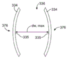
Energy exchange chamber 330 extends through the housing of LAMEE.Energy exchange chamber 330 extends to air outlet slit end 308 from air intake end 306.Air intake 322 receives air-flow 332, and air current flow is passed energy exchange chamber 330.Air-flow 332 is at air outlet slit 324 place's exhaust energy inverting chambers 330.Energy exchange chamber 330 comprises a plurality of plates 334.Each liquid flow plate forms liquid drier passage 376, and this drier passage 376 is limited by the pellicle 378 of any side, and drier passage 376 is configured to carry the drier 341 by wherein.Pellicle 378 is arranged in parallel, and to form air duct 336 and liquid drier passage 376, air duct 336 has mean flow path width (d
W, air) 337, liquid drier passage 376 has mean flow path width (d
W, liq) 377.In one embodiment, pellicle 378 is spaced apart, and has uniformly d to form
W, air Air duct 336 and have d
W, liqLiquid drier passage 376, can be by can being hinted by the actual factor G4 that reduces statistical fluctuation such as in the table 1 each.Air-flow 332 passes the air duct 336 between the pellicle 378.Drier 341 in each drier passage 376 is by air-flow 332 heat-shifts and moisture in pellicle 378 and the air duct 336.
Desiccant inlet chamber 338 is arranged on the bottom surface 318 of ladder rising.Desiccant inlet chamber 338 can have height 340, and the distance 320 between the bottom surface 318 of this height 340 and the rising of ground 316 and ladder equates.Alternatively, liquid drier entrance cavity 338 can have the pre-determined characteristics that satisfies LAMEE300.The length 339 of LAMEE main body 304 is extended in desiccant inlet chamber 338.Desiccant inlet chamber 338 development lengths 339, this length 339 is configured to satisfy the pre-determined characteristics of LAMEE300.In one embodiment, desiccant inlet chamber 338 be no more than LAMEE main body 304 length 327 1/4th.Alternatively, desiccant inlet chamber 338 can be extended along 1/5th of the length 327 of LAMEE main body 304.
Liquid drier entrance cavity 338 is configured to receive from shown in accumulator tank 128(Fig. 1) drier 341.Desiccant inlet chamber 338 comprises the entrance 342 that is communicated with accumulator tank 128 fluids.Pass entrance 342 and receive drier 341.Desiccant inlet chamber 338 comprises the outlet 344 that is communicated with drier passage 376 fluids in the energy exchange chamber 330.Liquid drier 341 flows and passes outlet 344 and enter drier passage 376.Drier 341 flows along plate 334 and passes drier passage 376 arrival drier outlet plenums 346.
Drier outlet plenum 346 is positioned on the end face 312 that the ladder of LAMEE housing 302 reduces.Alternatively, drier outlet plenum 346 can be positioned at along any position of the end face 312 of LAMEE housing 302, and perhaps drier outlet plenum 346 can be positioned on the side in described chamber alternatively, and this side has the flow channel that links to each other with all plates.Drier outlet plenum 346 has height 348, this height 348 can with end face 312 that end face 310 and ladder reduce between distance 314 equate.Drier outlet plenum 346 is along end face 312 development lengths 350 of LAMEE housing 302.In a kind of embodiment of contrary/cross-flow interchanger, the length 350 that drier outlet plenum 346 extends is no more than 1/4th length 327 of the length 302 of flow passage plate exchange area.In the another kind of embodiment of contrary/cross-flow interchanger, the length 350 that drier outlet plenum 346 extends be the plate exchange area length 302 1/5th length 302(namely, factor G3).
Drier outlet plenum 346 is configured to receive the drier 341 in the drier passage 376 that comes from energy exchange chamber 330.Drier outlet plenum 346 comprises the entrance 352 that is communicated with drier passage 376 fluids.It is received to pass entrance 352 from the drier 341 of drier passage 376.Drier outlet plenum 346 comprises the outlet 354 that is communicated with accumulator tank 128 fluids.Drier 341 flows and passes outlet 354 arrival accumulator tanks 128, and the drier 341 that is used for another LAMEE300 is stored in accumulator tank 128.In optional embodiment, drier outlet plenum 346 arranges along the bottom surface 318 of LAMEE housing 302, and desiccant inlet chamber 338 can arrange along the end face 310 of LAMEE housing 302.
In the embodiment shown, LAMEE300 comprises a liquid drier outlet plenum 346 and a liquid drier entrance cavity 338.Alternatively, LAMEE300 can comprise liquid drier outlet plenum 346 and the chamber, liquid inlet 338 on each of the end face of each section that is positioned at LAMEE and bottom surface.The liquid flow controller can guide to end face or bottom surface with liquid stream according to the P1 factor R a among independent factor group IF shown in the table 1.
(RAMEE system 100 has airflow balancing to the steady testing condition that limits in the 84-2008 standard of utilizing U.S. heating, Refrigeration ﹠ Air-Conditioning SE and the U.S. 1060-2005 of air-conditioning heating and refrigerating association standard at this moment, and be in very under the state near stable state) during testing ram EE system 100, define interchanger heat capacity ratio Cr*(operation independent factor P3 as shown in table 1).Cr* is the dimensionless ratio that amasss of long-pending mass flowrate with the thermal capacitance of air divided by air that represent the mass flowrate of liquid drier and liquid drier thermal capacitance.Flow velocity by measuring air and liquid drier and utilize the thermal capacitance of known air and liquid drier to measure Cr*.In one embodiment, when RAMEE tested, Cr* dropped in the scope of 1.0<Cr*<10.0.Equate and use in a kind of embodiment of belt heat-exchange system of two identical counterflow heat exchangers, at heat consumption rate and gross efficiency E at supply air flow and exhaust stream flow velocity
0When the highest, Cr* can equal 1.0.
When RAMEE tests, can also limit the number of mass transfer unit (operation independent factor P2 as shown in table 1) of the interchanger of heat transmission.Usually, the efficient of heat exchanger increases with the value direct ratio of NTU.Utilize the thermal capacity of air-flow 332 and drier 341 to determine the heat transmission of available maximum between air-flow and the drier 341.The temperature of two mass flowrates by measuring air, the air that passes the supply brethaid of flowing increases and the air that enters the supply brethaid is determined the supply air stream of RAMEE system and the heat transference efficiency between the discharge air stream with the temperature difference that enters the air of discharging brethaid.In one embodiment, NTU is in the scope of 1<NTU<15.Has the pre-determined characteristics that NTU in above-mentioned scope can provide the RAMEE system.In one embodiment, the scope of NTU can work simultaneously with other performance factors that limit herein, to obtain the pre-determined characteristics of LAMEE300 and RAMEE system 100.
When RAMEE100 tests, also can determine the Air Flow pressure drop rate (operational design factor P4 as shown in table 1) of LAMEE300.Utilize ratio p
hA
c/ V
cCalculate described Air Flow pressure drop rate, herein p
hThe air draught dynamic head reduction among the LAMEE300, A
cThe energy exchange area of each air flow passage among the LAMEE300, and V
cIt is the volume of each air flow passage.Utilize the Air Flow pressure drop rate to limit the air intake 322 of LAMEE300 and the pressure drop of the air-flow 332 between the air outlet slit 324.In one embodiment, the Air Flow pressure drop rate is 10
3To 10
4In the scope, to obtain the predetermined RER performance factor of RAMEE system 100.
Fig. 3 a shows the LAMEE300 that dissects along the line 3-3 among Fig. 2.The end face 310 of LAMEE housing 302 and bottom surface 318 comprise the heat preservation member 360 that is connected on end face 310 and the bottom surface 318.The side 326 of LAMEE housing 302 also comprises heat preservation member 360.Except air intake zone and air outlet slit zone, heat preservation member 360 is extended around energy exchange chamber 330.Heat preservation member 360 restrictions are when air and the mobile passage that passes in the energy exchange chamber of liquid drier, can be at the ratio (that is, factor P12) of the heat consumption rate of the flow heat that exchanges between the air pass described energy exchange chamber and liquid drier and the surrounding environment and supply air stream and exhaust stream.Heat preservation member 360 can comprise foam thermal insulation, fiber thermal insulation, gel insulation etc.Select heat preservation member 360 to satisfy at least in part the pre-determined characteristics of LAMEE300.
Energy exchange chamber 330 has height 362, length 364 and width 366.Height 362 is limited between the end face and bottom surface in energy exchange chamber 330.Width 366 is limited between the insulation sidewall in energy exchange chamber 330.Length 364 is limited between the air intake 322 and air outlet slit 324 in energy exchange chamber 330.Each energy exchange plate 334 extends height 362 and the length 364 in energy exchange chamber 330.Plate 334 is spaced apart along the width 366 in energy exchange chamber 330.
For contrary/cross-flow LAMEE, the drier inflow entrance 334 in desiccant inlet chamber 338 is communicated with energy exchange chamber 330 fluids at the air outlet slit end 308 of LAMEE300.The liquid drier outlet 352 air intake ends 306 at LAMEE300 of drier outlet plenum 346 are communicated with energy exchange chamber 330 fluids.Desiccant inlet chamber 338 and drier outlet plenum 346 are communicated with fluid passage 376 fluids.The non-linear liquid flow path 368 that plate 334 limits between desiccant inlet chamber 338 and the drier outlet plenum 346.In one embodiment, the drier flow direction of drier passage 376 is passed in control, so that low-density drier and high density drier flow separation.
Fig. 3 b has showed the front view of plate 334.Plate 334 is spaced apart, to form air duct 336 and liquid drier passage 376, is separated by pellicle 378 between air duct 336 and the liquid drier passage 376.Air duct 336 replaces with liquid drier passage 376.Except two side plates in energy exchange chamber, each air duct 336 is between adjacent two liquid drier passages 376.Liquid drier passage 376 is between two air ducts 336.Liquid drier passage 376 has the average channel width 337 that is limited between adjacent two plates 334.Except the situation of the independent geometry designs factor G4 shown in the table 1 and G5, in one group of plate in each plate and LAMEE energy exchange chamber, the width 337 of air duct 336 and the width 377 of liquid drier passage 376 are near constant.In one embodiment, the standard deviation of average channel hydraulic diameter (directly related with the average channel width 377 of the width 337 of air duct 336 or liquid drier passage 376) is the independent geometry designs factor (the physical Design factor G4 shown in the table 1) divided by the average channel hydraulic diameter of corresponding every kind of fluid, one group of predetermined performance factor Pf that fluid passage one at least part of acquisition that this independent geometry designs factor restriction is every type has the RAMEE system of LAMEE300.In another embodiment, the statistical fluctuation of stream pipe hydraulic diameter will be so that the stream pipe hydraulic diameter standard deviation of the flow channel of the general type among the LAMEE be subject to the restriction of factor G5 clear and definite in the table 1 divided by the average flow pipe hydraulic diameter of the common flow channel of fluid.
Fig. 4 has showed the plate 334 according to a kind of embodiment, to hold the liquid stream of a passage.Plate 334 comprises supporting construction, and this supporting construction comprises that top braces 370, bottom support 372 and a pair of relative side relative with top braces 370 support 374, and this offside supports 374 and extends between top braces 370 and bottom support 372.Top braces 370, bottom support 372 and side support 374 and keep film 392 and liquid drier inlet diffuser 396 and drier outlet diffuser 400.Plate 334 comprises end face 381 and bottom surface 383.Plate 334 has the total height 382 that is limited between end face 381 and the bottom surface 383.Energy exchange film 392 comprises end face 385 and bottom surface 387.Film 392 has total height 384 between the end face of being limited to 385 and the bottom surface 387.The height 384 of film 392 is less than the height 382 of plate 334.Plate 334 has front end 389 and rear end 391.Plate 334 has total length 386 between the front end of being limited to 389 and the rear end 391.Film 392 comprises the air intake that corresponds respectively to adjacent air flow passage and front end 393 and the rear end 395 of air outlet slit.Film 392 has the total length 388 that is limited between front end 393 and the rear end 395.The total length 388 of film 392 is less than the length 386 of plate 334.Can be at least according to the pre-determined characteristics structure height 382 and the ratio of length 386 and the ratio of height 384 and length 388 of part according to LAMEE300.In a kind of embodiment of contrary/cross-flow plate, the height 384 of film 392 multiply by in the scope of length 388 of film 392 (that is, factor G2) 0.1 to 3.0.
Plate 334 has desiccant inlet end 378 and the drier port of export 380.Drier flow path 368 has showed that the fluid in the relative non-linear mobile path of basic and air-flow 332 exports 400 mobile common overall average streamline from liquid drier entrance 396 to drier.Desiccant inlet end 378 comprises entrance 390, and this entrance 390 extends through bottom support 372, and entrance 390 is between adjacent plate 334.Entrance 390 has length 396.Select the ratio of length 396 with the length 388 of plate 334 of entrance 390 according to the pre-determined characteristics of described LAMEE.The drier port of export 380 comprises outlet 398, and this outlet 398 extends through top braces 370, and between adjacent plate 334.Outlet 398 has length 400, and this length 400 equals entrance length 396.At least part of pre-determined characteristics according to LAMEE300 is selected the ratio of length 400 with the length 388 of plate 334 of outlet 398.Drier flow path 368 flows to outlet 398 from entrance 390.
Liquid drier flow path line 368 is the same with a rational population mean streamline (bulk-meanstreamline) pass LAMEE contrary/the cross-flow plate, described rational population mean streamline is especially crooked necessarily near the pharyngeal district of the liquid of described passage (liquid ingest region) and liquid discharge oral region (egressregion).The population mean air flow line 332 of the streamline of described bending and air duct 336 interior basic straight lines forms contrast.Described population mean liquid drier flow path direction or speed almost are the flow path direction of the population mean air-flow 332 in the adjacency channel or the upstream of speed.Along with drier enters drier passage 376 from entrance 390, be formed with entrance with the section 402 of the liquid drier population mean streamline 368 cross-flows pharyngeal district (inlet flow ingest region) of flowing.The entrance that the liquid drier 341 that flows into drier passage 376 from entrance 390 passes cross-flow section 402 upwards flows.Liquid drier 341 in the entrance cross-flow section 402 partly edge is mobile with the staggered direction of flow direction of the air flow passage streamline 332 of vicinity.
Because liquid drier 341 is guided from entrance 390, so drier 341 is full of passage 376, and the mobile basic adverse current section of air/liquid that passes liquid drier ensemble average streamline 368.Liquid/air adverse current section 404 approximately passes liquid drier flow channel 376 development lengths 406.This length 406 depends in part on the pre-determined characteristics of LAMEE300.Liquid/air adverse current section 404 is parallel to the direction of the air-flow 332 in the air duct 336 in essence.Liquid/air adverse current section 404 has the opposite liquid of flow direction and adjacent air stream 332.Counterflow configuration provides predetermined amount of heat and the exchange of moisture efficient between the interior air-flow 332 of liquid drier 341 and the air duct 336 in the drier passage 376 at least in part.
Liquid driers 341 in the adverse current section 404 flow into liquid drier flow path 368 contrary/cross-flow liquid flow outlet area 408.Liquid drier 341 in contrary/cross-flow liquid flow outlet area 408 flows to outlet 398 with the population mean streamline of bending from adverse current section 404.Liquid drier 341 in contrary/cross-flow liquid flow outlet area 408 is at least in part along the cross flow directions with respect perpendicular to the direction of the air-flow 332 in the air duct 336.
Liquid drier population mean streamline flow path 368 contrary/the cross-flow setting provides almost the liquid drier with respect to air-flow 332 adverse currents.Compare with having the mass flowrate, entrance characteristic and the unit in interchanger energy exchange zone that equate, described adverse current setting has been improved the efficient of LAMEE300.Described contrary/the cross-flow setting do not need to increase the large head in the required space of LAMEE300.Shown embodiment has been showed the drier flow path 368 that travels up to outlet 398 from entrance 390.Alternatively, entrance 390 can be positioned on the top braces 370 but be positioned at the same end of plate 334, and exports 398 and can be arranged on the bottom support 372 but be positioned at the same end of plate 334.In this embodiment, drier flow path 368 can flow downward to outlet 398 from entrance 390.Can avoid the unstability that one or two LAMEE internal cause buoyancy of the RAMEE system of common summer or winter operation produces like the selective flow direction and the bad distribution of the fluid passage stream that causes.
Fig. 5 a is the exploded view of liquid drier flow plate 334.Plate 334 comprises that movement-oriented of liquid drier and current stabilization strengthen screen cloth diffuser 410 and a pair of pellicle 412.Liquid drier screen cloth diffuser 410 remains between the pellicle 412.Pellicle 412(is by heat-sealing or glue) be bonded to film support component 418,424.Film mesh support screen 414 in the adjacent air flow passage 336 can also comprise the air flow passage interval.The air duct mesh support screen can comprise the solid area, and this solid area is the part of the air duct mesh support screen gross area.In addition, drier passage mesh support screen can have the solid area, the part of the drier passage mesh support screen gross area during area of this lowest point.In one embodiment, the air duct mesh support screen along the distance between the air current flow direction divided by the air duct mesh support screen along perpendicular to the distance between the air current flow direction in 0.01 to 5.0 scope.Air flow passage 336 is formed between the liquid drier flow plate 334 that closes on.Drier 341 is configured to have the population mean that is parallel to pellicle 412 and flows.Heat-shift and moisture between the air-flow 332 that flows in working fluid drier 341 in the pellicle 412 permission drier passages 376 and the air duct 336.Film 412 is semi-transparent, and is formed with the hole of highdensity micron-scale, and the hole permission water vapor diffusion of this micron-scale is passed the film 412 between liquid drier 341 and the air-flow 332.Because the enough tension force of solution-air, the size in described hole prevent the liquid drier 341 mobile holes of passing film 412.Can partly select semipermeable membrane material according to the pre-determined characteristics of LAMEE.
Fig. 5 b is the more detailed view that comprises the air flow passage of two films, two support structure screen clothes and a plurality of air flow passage spacing structures.In optional design, under love and respect that and can be the porous rigid pipe.The parameter of the flexible membrane of support air passage is determined by factor G7 structurally.
Can be partly according to water vapor diffusion resistance (R
M, wv) divided by the convection current water vapor transmission resistance (R that enters contiguous air duct
Air, wv) (independent operation design factor P4 as shown in table 1) select the material of described film.Water vapour resistance (R
M, wv) be defined as film resistance water vapour by the resistance of film 412 diffusions between air duct 336 and the fluid passage 376.Convection current water vapor transmission resistance (R
Air, wv) be defined as that ensemble average that film stops the gas of water vapour in air duct 336 flows and fluid passage 376 between the ability transmitted by pellicle 412.Water vapor diffusion resistance (the R of pellicle 412
M, wv) with the convection current water vapor transmission resistance (R of pellicle 412
Air, wv) ratio can be the scope among the factor P4: 0.1<(R
M, wv)/(R
Air, wv)<3.0.In one embodiment, above-mentioned ratio actual selection is for very little.
Can also partly pass pressure (operational design factor P7 as shown in table 1) the selection pellicle 412 of film 412 according to liquid.Limit liquid by standard testing (liquid drier 341 flows and passes fluid pressure among the required LAMEE300 of pellicle 412) and pass pressure.In one embodiment, factor P8, film liquid passes pressure (p
M, bt) be chosen as and satisfy inequality (p
M, bt)/(rho*g*H)>20, wherein rho is the density of liquid desiccant solutions, and g is that gravity accelerates, and H is the height of the pellicle in the energy exchange zone on surface of each passage.Pass through p
M, bt/ (rho*g*H) limit liquid to pass pressure ratio p wherein
M, btFor film liquid passes pressure, g is that gravity accelerates, and H is the height of the pellicle in the energy exchange zone on surface of each passage.In one embodiment, film liquid pass pressure can be greater than 20.
The channel edge seal fluid passes pressure (p
Es, bt) (the operational design factor P8 shown in the table 1) define flow pressure in the needed LAMEE300 of sealing the margin that passes film 412 of drier 341.The channel edge seal fluid passes pressure (p
Es, bt) be chosen as and satisfy inequality (p
Es, bt)/(rho*g*H)>20.When the operating pressure of liquid flow path less than p
M, btOr p
Es, btThe time, can not pass the liquid of film 412 or edge seal and reveal.In one embodiment, the channel edge seal fluid pass pressure can be greater than 20.
Can be at least part of according to elastic stretching yield limit (T
M, yl) (operational design factor P9 as shown in table 1) selective membrane material.Described elastic stretching yield limit (T
M, yl) define the elastic deformation limit of described film when being subject to flowing through the fluid pressure of the drier 341 in the drier passage 376.In one embodiment, factor P9, the described elastic stretching yield limit (T of film 412
M, yl) will drop on 0.02<(T
M, yl)/(p
L, op* s
WsIn the scope of)<1.5, wherein, p
L, opThe normal operations pressure of the liquid among each LAMEE, s
WsIt is the netting twine spacing distance of the air side screen cloth 416 that is used for the prevention fluid pressure of each drier passage 376.The operating pressure of LAMEE is defined as the value of the elastic deformation limit of a film 412 that can not surpass each drier passage 376.The elastic stretching yield limit ratio of film is defined as T
M, yl/ (p
L, op* s
Ws), wherein, T
M, ylThe elastic stretching yield limit of film, p
L, opThe normal operations pressure of the liquid among each LAMEE, s
WsIt is the netting twine spacing distance of the screen cloth that is used for the prevention fluid pressure of each drier passage.
Adjacent membrane 412 arranges film air side screen cloth supporting construction 414.Each film 412 is between air side form supporting construction 414 and drier flow channel liquid-mobile-guiding screen cloth diffuser 410.Film supporting construction 414 keeps film 412, with the elastic deflection of restriction film 412.Because fluid pressure is higher than the static pressure of contiguous air duct 332, so film 412 will deflect.Liquid drier will produce pressure at film 412, and this pressure causes film 412 bendings and/or strain.Control a little the bad distribution of mass flow of adjacent hydraulic fluid side and air side, with control RAMEE system and the operation of LAMEE and design and the quality of manufacture process.
In a kind of illustrative embodiments, film air side supporting construction 414 has screen material to form.Alternatively, film supporting construction 414 can be formed by permeable substrate (backing), plastic supporting structure, bar, metallic sieve, interval and/or similar structures.Film supporting construction 414 comprises the hole 416 of passing this film supporting construction, and this hole 416 allows transferring heat and moisture between liquid drier and air-flow 332.
Supporting construction interval, hydraulic fluid side 418,424 arranges around the movement-oriented screen cloth 410 of liquid drier.Described interval separates two films 412 of border 418,424 each side at the interval.Film 412 links to each other with diffuser interval 418, to form interval or liquid flow path between each film 412.The Air Flow entrance that end 424,420 forms liquid flow plate 334 supports and Air Flow outlet support.The end face 422 at a liquid flow path interval 418 forms the part of the top braces 370 of liquid flow plate 334.The bottom 424 at another liquid flow path interval 418 forms the part of the bottom support 372 of liquid flow plate 334.Top braces 370 and bottom support 372 also form by air duct interval 426.Air flow passage interval 426 is configured to the air duct interval 426 on the contiguous adjacent panel 334.The Air Flow interval that air duct interval 426 forms between the adjacent Air Flow plate 334.Air Flow interval between the adjacent liquid flow plate 334 in the energy exchange chamber forms air duct 336.
Fig. 6 a has showed the air duct 336 between the adjacent film that is formed on liquid flow plate 334.Air duct 336 is configured to carry the air-flow 332 by this air duct 336.Air duct 336 is designed to have uniform width 430 along the length 432 of this air duct 336.Yet because the strain of the film supporting construction 414 of plate 334, the air duct width may have significant change.Air side form supporting construction 414 restriction film amount of deflections, the width of this film amount of deflection restriction air flow passage, and this film amount of deflection is caused by the output value between the static pressure of the static pressure of fluid passage 334 and air duct 332.For example, film supporting construction 414 limits the deflection of the fraction of each film, but film supporting construction 414 limits the deflection of each film in finite region.About factor G4, the air flow passage of common independent stream pipe hydraulic pressure radius and the statistical fluctuation of liquid flow path can be limited.About factor G3, the average channel width statistical fluctuation of every kind of fluid in LAMEE in all passages can be limited.
Fig. 6 b has showed a kind of air flow passage 336, and this air flow passage 336 is at the adjacent liquid flow path of the smaller portions internal cause of Air Flow plate 334 and the liquia air differential static pressure between the air flow passage and be out of shape.Utilize the quality of liquid of LAMEE of common liq pressure or the measured value of volume, the measuring laser beam value of the moving passage of the drop measurement value of the careful development in the flow channel of every kind of fluid and minimum air flow can be derived the statistical fluctuation of the deflection of the film in air flow passage and the liquid flow path.Can use described measured value with the hydraulic diameter standard deviation (can be determined independently by the common passage (factor G4) among each LAMEE and the one group of passage (factor G3) among each LAMEE) of average hydraulic diameter and every kind of fluid of definite air and fluid passage with other data subsequently.Known data can be partly depended in the Design and manufacture quality control of LAMEE and operation.
Fig. 7 shows as the air humidity content of the passive RAMEE system curve map 450 with the analog result of the preferred heat capacity rate ratio of the parameter on the chart of air temperature variations, described RAMEE system is in the operating condition of stable state, and this operating condition has the room air of the wider hypothesis of outdoor air condition and range.Curve map 450 has been showed the preferred value of heat capacity rate ratio line 452.Should select to have the above-mentioned preferred value of ceiling capacity transmission efficiency of the RAMEE system of two identical LAMEE unit.Described two restrictions that identical LAMEE unit is supposed, this hypothesis be restricted to the even width (there is no inner supporting structure) that each and each air duct have 4.4mm, the liquid drier passage has the even width (also not having inner supporting structure) of 2.7mm, the film water steam permeability is 1.66E-6kg/ (m*s), and has laminar-flow air and the laminar flow stream of ripe development in each passage.As described below, for different operating conditions and how much ratios, curve map 450 may have different preferred Cr* values.
Have the air duct of constant width of hypothesis and drier channel width and be a kind of example of theoretical case for the result that various fluids have a preferred thermal capacitance ratio of ripe laminar flow, having in this example visibly different is physical possibilities.Although the channel width and the current stabilization channel flow that change, it will be very complicated representing identical result for these conditions, utilize identical hypothesis process to obtain.Under this condition, under identical open-air condition, preferred thermal capacitance ratio will be very different from the represented preferred thermal capacitance ratio of curve map 450.
Utilize curve map 450 to have the preferred stable state efficient (energy transport) of the passive RAMEE system of two identical LAMEE with acquisition as design and the exemplary displaying of operating process, described system operator or automatic controller are according to the temperature and humidity selection of open-air condition or the pump rate of control liquid drier, and each described LAMEE bears identical air mass flow rate.That is, when knowing the mass flowrate of air, select the preferred thermal capacitance ratio 452 of specific outdoor environment to calculate the mass flowrate of liquid drier.Utilize described result to set preferred pump rate.When the open-air condition changes obviously or air flow rate changes when obvious, determine new best pump rate.In one embodiment, the flow rate of control drier and the ratio of the flow rate of air-flow, with the switching performance ratio that obtains to be scheduled to, this predetermined switching performance is than the sensible heat and the latent heat energy exchange that define at least in part between drier and the air-flow.
The curve map 500 of Fig. 8 has been showed balance, saturated, the salinity curve 502 of several salt of the liquid drier that may be used as system 100, and this curve 502 is superimposed upon on the temperature variant hygrogram of water capacity.Curve map 500 has been showed the temperature 504 of the air that flows through LAMEE and has been passed through the humidity ratio 506 of LAMEE in the standard atmospheric pressure current downflow.Described balance, saturated, type that salinity curve 502 only depends on salt and drier begin crystallization in the plate of LAMEE temperature 504 and water capacity 506.Under saturated concentration, any one of the temperature of adjacent air flow passage or water capacity reduces (that is, being lower than the curve 502 of specific salts), and specific salting liquid is all separated out salt with nigh film surface.Pass the ideal conditions of the specific climatic province of LAMEE according to Air Flow, curve 500 can use with other data, to select to be used for the suitable drier of the airflow condition that HVAC uses.
Air themperature 504 and water capacity 506 near line 508 representatives, under the condition of this temperature 504 and water capacity 506, if air themperature or humidity are lower than line 508, saturated magnesium chloride solution is with crystallization.The crystallization line of the saturated calcium chloride solution that line 510 representatives are similar.The crystallization line of the saturated lithium iodide solution that line 512 representatives are similar.The crystallization line of the saturated lithium chloride solution that line 514 representatives are similar.The crystallization line of the saturated lithium bromide that line 516 representatives are similar.
Because only when contiguous air humidity content is very low, just can cause lithium bromide to be separated out, so lithium bromide can be as the liquid drier in the severe rugged environment.Yet, to compare with other salt that do not contain lithium, lithium bromide is relatively expensive.In a kind of illustrative embodiments, system 100 utilizes the mixture of magnesium chloride and other salt as drier.Described mixture can comprise at least one in magnesium chloride and lithium chloride or the lithium bromide.Alternatively, described mixture comprises that calcium chloride replaces at least one in magnesium chloride and lithium chloride or the lithium bromide.In another embodiment, described mixture comprises at least three in magnesium chloride, calcium chloride, lithium chloride and/or the lithium bromide.The concentration of magnesium chloride can be 0% to 35.5%(namely, saturated salt concentration) scope in.In curve map 500, above for the described saturated salt solution line of specific salt, balanced salt concentration depends on the temperature and humidity of the air that passes LAMEE of flowing.Salting liquid comprises water and salt ion.The concentration of lithium chloride can be in 0% to 45.9% scope (that is, saturated salt concentration).In one embodiment, described mixture is 50% magnesium chloride and 50% lithium chloride.Can operate described mixtures and crystallization not occur in temperature 504 and the water capacity 506 of line below 508 of magnesium chloride.Compare with pure magnesium chloride solution or pure calcium chloride solution, described mixture provides a kind of drier that can operate under the open-air condition of more dry air conditions as the RAMEE system.
In one embodiment, select described drier according to the operational design factor P10 shown in the table 1 and P11.Can be according under the weather conditions that are in the building in the specific weather, the duration (t of crystallization risk in the salting liquid in the annual drier
Salt, risk) the selection drier.Especially, the crystallization risk duration (t of drier
Salt, risk) divided by the annual duration (t of described system's operation
Op).In one embodiment, parameter P10 is at t
Salt, risk/ t
OpIn<0.15 the scope.In another embodiment, according to the cost of the mixture of the salt that uses in the RAMEE system 100 or the salt cost (C divided by the LiCl in the corresponding system
Salt, mix/ CLiCl) select described drier.In one embodiment, parameter P11 is at C
Salt, mixIn the scope of/CLiCl<1.Can select independently parameter P10 and parameter P11 to obtain the pre-determined characteristics of LAMEE300 and RAMEE system 100.In another embodiment, design parameter P10 and P11 may be used to the performance that obtains to be scheduled to.
Geometry designs shown in can option table 1 and operations factor G1 to G8 and physical operations and design factor P1 to P12 are to obtain the pre-determined characteristics of LAMEE300 and/or RAMEE system 100.Can select respectively geometrical factor G1 to G10 and physical agent P1 to P12 to obtain the pre-determined characteristics of LAMEE300 and/or RAMEE system 100.In another embodiment, can select several at least to obtain the pre-determined characteristics of LAMEE300 and/or RAMEE system 100 among geometrical factor G1 to G10 and the physical agent P1 to P12.
When the LAMEE device that is used for passive RAMEE system is used for recovering energy, be enough in the application of performance parameter hereinafter for the system that in nearly stable state, operates.When the RAMEE that is used for adjusting supply air that the LAMEE device is installed in ACTIVE CONTROL and HVAC system, most of above-mentioned LAMEE performance factor stands good, but can utilize different dimensionless ratio to limit the performance of HVAC system.For this purpose, the any common stable state of the RAMEE system of control or nearly steady state operation condition can serviceability coefficient (COP) or energy efficiency ratios (EER), and can revise described ratio to be used for being positioned at the heating and cooling of town building with respect to annual generalized time mean value (so-called seasonal energy efficiency ratio (seer) (SEER)).The COP of HVAC system or EER are restricted to available energy exchange rate from the supply air of entrance and conditions of discharge divided by all supplementary energy rates of inputting in the HVAC system.Can irregularly measure or the data of COP or EER be used for are calculated in continuous measurement.
Since usually very different with the consumption of heating auxiliary energy for cooling, described ratio should be treated respectively.The SEER value that can be independent of heating supply in winter air for the SEER value at cooling supply in summer air is enumerated.Because machinery cooling and drier dehumidification system have all used heating and cooling, so in operating summer, can use the input energy of two kinds of forms.In order to obtain the high SEER of the HVAC system in the building, the RAMEE system is direct to regulate or part adjusting supply air to utilize can to use the energy of wasting in exhaust and other process energy, perhaps utilizes the indirect environment for use air of heat pump (and/or refrigeration machine) or underground water as the energy.Utilize branch road energy conservation device also can produce SEER.
When the whole year, utilization was in the RAMEE system of the correction in aggressive mode and the Passive Mode, the SEER value of calculating the HVAC system should be considered variation and any additional energy for all energy recovery or pumping energy of pattern.
In selecting for active HVAC discussed above system, clearly the scope of high SEER value is easy to obviously change identical building or the different building in the Different climate.Can utilize software to finish the comparison of dimensionless performance ratio of RAMEE system of the correction of the intrasystem ACTIVE CONTROL of HVAC, with life cycle cost and the Payout Period of the saving that is illustrated in the particular design in the specific weather.The passive performance of RAMEE system is also very useful, because this passive performance directly changes with the cost savings that recover energy, and described passive performance can provide for RAMEE system and two LAMEE the optimal quantization evidence of performance.Equally, can directly use the performance of described passive Performance Evaluation HVAC system, this HVAC system has the auxiliary RAMEE system of heat pump and cost savings.
Fig. 9 has showed the LAMEE200 that forms according to a kind of optional embodiment.This LAMEE200 can be as supply air LAMEE108 and/or return air LAMEE120(as shown in fig. 1).LAMEE200 comprises housing 202, and this housing 202 has main body 204.Main body 204 comprises front 206 and the back 208 relative with this front 206.Main body 204 is included in the height 216 that extends between end face 212 and the bottom surface 214.Main body 204 comprises the first side 218 and the second side 220.The length 210 that the first side 218 and the second side 220 are crossed between front 206 and the back 208.The first side 218 and the second side 220 are crossed over height 216 between end face 212 and the bottom surface 214.The first side 218 and the second side 220 are set parallel to each other, and the first side 218 and the second side 220 are separated by width 222.
LAMEE main body 204 forming energy inverting chambers 224.Energy exchange chamber 224 in front 206 and back 208 between development length 210, extended height 216 between end face 212 and the bottom surface 214 and between the first side 218 and the second side 220 extension width 222.Length 210, height 216 and/or width 222 show as dimensionless physics ratio with the ratio of height 216, and more generally, the position dimensionless design factor.
Energy exchange chamber 224 comprises a plurality of energy exchange plates 226 that extend through this energy exchange chamber 224.Plate 226 extends the length 210 in energy exchange chamber 224 and the height 216 in energy exchange chamber 224.Each plate 226 forms the drier passage of carrying drier 241, and this drier passage passes energy exchange chamber 224.Plate 226 is set parallel to each other, and apart from one another by between plate 226, to form air duct 230 and drier passage 231.Air duct 230 extends between air intake 205 and air outlet slit 207.Each air duct 230 is formed between the adjacent drier passage 23 1.Air duct 230 guides to air-flow 234 back 208 of LAMEE200 from the front 206 of LAMEE200.
Desiccant inlet housing 236 engages with LAMEE housing 202.In the embodiment shown, desiccant inlet housing 236 engages with the bottom surface 214 of LAMEE housing 202.Desiccant inlet housing 236 is arranged near the back 208 of LAMEE housing 202.Desiccant inlet housing 236 extends along the bottom surface 214 of LAMEE housing 202 from the back 208 of LAMEE housing 202.Desiccant inlet housing 236 partly extends between the back 208 of LAMEE housing 202 and front 206.Alternatively, desiccant inlet housing 236 can be arranged on any position along LAMEE main body 204.In one embodiment, LAMEE200 can comprise a plurality of desiccant inlet main bodys 204.Desiccant inlet housing 236 is along bottom surface 214 development lengths 238 of LAMEE housing 202.The length 238 that desiccant inlet housing 236 extends depends on the pre-determined characteristics of LAMEE200.In one embodiment, desiccant inlet housing 202 extend not more than LAMEE main body 204 length 210 1/4th.In another embodiment, 1/5th of the length 210 of desiccant inlet housing 236 extension LAMEE main bodys 204.
Desiccant inlet housing 236 comprises entrance 240 and outlet 242.Entrance 240 is configured to receive from shown in accumulator tank 128(Fig. 1) drier 241.Entrance 240 and outlet 242 are communicated with drier passage 231 fluids that extend through energy exchange chamber 224.Drier 241 flows into drier passage 231 from desiccant inlet housing 236.Drier 241 flows towards the front 206 of LAMEE housing 202 from the back 208 of LAMEE housing 202 and passes drier passage 231.Drier 241 flows along the direction opposite with the flow direction of air stream 234.Drier 241 flows towards drier outlet housing 244 and passes drier passage 231.
Drier outlet housing 244 engages with the end face 212 of LAMEE housing 202.Drier outlet housing 244 is positioned near the front 206 of LAMEE housing 202.Alternatively, drier outlet housing 244 can be positioned at along any position of the end face 212 of LAMEE housing 202.Drier outlet housing 244 departs from desiccant inlet housing 236 along the direction of air-flow 234.The end face 212 of drier outlet housing 244 along the end face 212 of LAMEE housing 202 from this LAMEE housing 202 begins to extend.Drier outlet housing 244 partly extends between the front 206 of LAMEE housing 202 and back 208.Drier outlet housing 244 is along the end face development length 246 of LAMEE housing 202.The length 246 that this drier outlet housing 244 extends depends on the pre-determined characteristics of LAMEE200.In one embodiment, drier outlet housing 244 length 246 of extending be no more than LAMEE main body 204 channel energy exchange length 210 1/5th.In one embodiment, drier outlet housing 244 length 246 of extending be that the channel energy of LAMEE main body 204 exchanges 1/5th of length 210.
Drier outlet housing 244 comprises entrance 248 and outlet 250.Entrance 248 is communicated with drier passage 231 fluids.The drier 241 that drier outlet housing 244 receives from drier passage 231.Drier outlet housing 244 guiding drier 241 pass outlet 250.Outlet is 250 with shown in accumulator tank 128(Fig. 1) fluid is communicated with.
The non-linear mobile path 252 that desiccant inlet housing 236 and drier outlet housing 244 form by plate 226.Drier flow path 252 flows along the direction opposite with air-flow 234.Drier flow path 252 existing direction flow upstream for air-flow 234.Drier flow path 252 is the path of passing the air-flow 234 contrary/cross-flows of air duct 230 with respect to mobile.Along with drier 241 enters plate 226 from desiccant inlet housing 236, form the entrance cross-flow section 254 of drier flow path 252.The drier 241 that flows into plate 226 from desiccant inlet housing 236 upwards flows and passes entrance cross-flow section 254.Drier in the entrance cross-flow section 254 flows along cross-flow setting (namely being approximately perpendicular to the direction of air-flow 234).
Be full of plate 226 along with drier 241 guides to from desiccant inlet housing 236, drier 241 begins mobile countercurrent zone 256 of passing drier flow path 252.Adverse current section 256 passes plate 226 development lengths 258.Length 258 depends on the pre-determined characteristics of LAMEE.The direction that adverse current section 256 is roughly parallel to air-flow 234 flows.Adverse current section 256 is with respect to air-flow 234 flow upstream.The adverse current setting provides heat and the exchange of moisture of being scheduled between the air-flow 234 in drier and the air duct 230 in the plate 226.
Drier 241 in the adverse current section 256 flows in the outlet cross-flow section 260 of drier flow path 252.The direction that outlet cross-flow section 260 is approximately perpendicular to air-flow 234 flows.Drier edge in the outlet cross-flow section 260 is with respect to the air-flow 234 cross-flow settings in the air duct 230.Drier in the outlet cross-flow section 260 travels up to drier outlet housing 244 from adverse current section 256.
The mistake of drier flow path 252/adverse current setting provides the drier adverse current with respect to the direction of air-flow 234.Adverse current arranges the efficient that improves LAMEE200.Mistake/adverse current setting does not need to increase the large head of LAMEE200 requisite space.Shown embodiment has been showed the drier flow path 252 that travels up to the end face 212 of LAMEE200 from the bottom surface 214 of LAMEE200.Alternatively, desiccant inlet housing 236 can be positioned on the end face 212 of LAMEE200, and drier outlet housing 244 can be positioned on the bottom surface 214 of LAMEE200.In this embodiment, drier flow path 252 can flow downward to from the end face 212 of LAMEE200 the bottom surface 214 of LAMEE200.
Should utilize the geometry designs factor G1 to G8 shown in the table 1 and physical operations and design factor P1 to P12 to obtain the pre-determined characteristics of LAMEE.Although each independent factor in the group factor (G1 to G8 and P1 to P12) should be selected in the concrete scope shown in the table 1, pre-determined characteristics with the passive RAMEE system with two LAMEE200 unit that obtains under stable state, to operate, but, for narrower independent factor of some scopes in the table 1, design and opereating specification can be relaxed, and still acceptable systematic function can be obtained.Therefore, in another embodiment, as LAMEE200 during as the part test of passive RAMEE system, only be that some factor among G1 to G8 and the P1 to P12 need to be selected in the scope defined in table 1, to obtain the acceptable pre-determined characteristics of LAMEE200.
Figure 10 has showed the LAMEE600 that forms according to a kind of optional embodiment.This LAMEE600 comprises housing 602, and this housing 602 has main body 604, and this main body 604 has end face 606 and bottom surface 608.LAMEE600 comprises air intake 610 and air outlet slit 612.Energy exchange chamber 614 extends through main body 604 between air intake 610 and air outlet slit 612.Air-flow 616 flows from air intake 610 and passes energy exchange chamber 614 arrival air outlet slits 612.Energy exchange chamber 614 comprises plate 618, and this plate 618 forms drier passage 615, and drier is wherein passed in these drier passage 615 carryings.
Desiccant inlet 620 is arranged on 608 places, bottom surface of LAMEE main body 604.Desiccant inlet 620 can be positioned at along the optional position of the bottom surface 608 of LAMEE main body 604.Alternatively, LAMEE600 can comprise the desiccant inlet 620 of any amount.Desiccant inlet 620 is communicated with drier passage 615 fluids.The first drier outlet the 622 and second drier outlet 624 is positioned at end face 606 places of LAMEE main body 604.The first drier outlet the 622 and second drier outlet 624 can be positioned at along the optional position of the end face 606 of LAMEE main body 604.The outlet 624 of the first drier outlet the 622 and second drier is offset from desiccant inlet 620 along the direction of air-flow 616.Desiccant inlet 620 and drier outlet 622,624 form from the drier flow path of the end face 606 of bottom surface 608 to the LAMEE main bodys 604 of LAMEE main body 604.Alternatively, desiccant inlet 620 can arrange along the end face 606 of LAMEE main body 604, and drier outlet 622,624 can arrange along the bottom surface 608 of LAMEE main body 604.In this embodiment, drier flows to the bottom surface 608 of LAMEE main body 604 from the end face 606 of LAMEE main body 604.
Desiccant inlet 620 and the first drier outlet 622 have formed the first drier flow path 626, and these the first drier flow path 626 non-linear flowing are passed plate 618.The first drier flow path 626 comprises the entrance 628 that begins to flow from desiccant inlet 620.This entrance 628 is along the cross flow directions with respect that is approximately perpendicular to the direction of air-flow 61 6.Entrance 628 flows into interlude 630, and this interlude 630 flows along the direction that is roughly parallel to air-flow 616.The flow direction of interlude 630 is identical with the direction of air-flow 616.Interlude 630 flows into outlet section 632, and this outlet section 632 flows to drier outlet 622.Outlet section 632 flows along the direction of the direction that is approximately perpendicular to air-flow 616.
Desiccant inlet 620 and the second drier outlet 624 form the second drier path 634, and these the second drier path 634 non-linear flowing are passed plate 618.The second drier flow path 634 comprises the entrance 636 that begins to flow from desiccant inlet 620.This entrance 636 is along the cross flow directions with respect that is approximately perpendicular to the direction of air-flow 616.Entrance 636 flows into interlude 638, and this interlude 638 flows along the direction that is roughly parallel to air-flow 616.The opposite direction of the flow direction of interlude 638 and air-flow 61 6.Interlude 638 flows into outlet section 640, and this outlet section 640 flows to drier outlet 624.Outlet section 640 flows along the direction of the direction that is approximately perpendicular to air-flow 616.
Can utilize the physical Design geometrical factor G1 to G10 shown in the table 1 and operational design factor P1 to P12 to obtain the pre-determined characteristics of LAMEE600.Can select each among physical Design geometrical factor G1 to G10 and the operational design factor P1 to P12, to obtain the pre-determined characteristics of LAMEE600.In another embodiment, only select among physical Design geometrical factor G1 to G10 and the operational design factor P1 to P12 some to obtain the pre-determined characteristics of LAMEE600.
Figure 11 has showed the LAMEE650 that forms according to a kind of optional embodiment.LAMEE650 comprises housing 652, and this housing 652 has main body 654, and this main body 654 has end face 656 and bottom surface 658.LAMEE650 comprises air intake 660 and air outlet slit 662.Energy exchange chamber 664 extends through main body 654 between air intake 660 and air outlet slit 662.Air-flow 666 flows from air intake 660 and passes energy exchange chamber 664 arrival air outlet slits 662.Energy exchange chamber 664 comprises plate 668, and this plate 668 forms drier passage 669, and drier is wherein passed in these drier passage 669 carryings.
Drier outlet 670 is arranged on end face 656 places of LAMEE main body 654.Drier outlet 670 can be positioned at along the optional position of the end face 656 of LAMEE main body 654.Alternatively, LAMEE650 can comprise the drier outlet 670 of any amount.Drier outlet 670 is communicated with drier passage 669 fluids.The first desiccant inlet 672 and the second desiccant inlet 674 are positioned at 658 places, bottom surface of LAMEE main body 654.The first desiccant inlet 672 and the second desiccant inlet 674 can be positioned at along the optional position of the bottom surface 658 of LAMEE main body 654.The first desiccant inlet 672 and the second desiccant inlet 674 are offset from drier outlet 670 along the direction of air-flow 666.Drier outlet 670 and desiccant inlet 672,674 form from the drier flow path of the end face 656 of bottom surface 658 to the LAMEE main bodys 654 of LAMEE main body 654.Alternatively, drier outlet 670 can arrange along the bottom surface 658 of LAMEE main body 654, and desiccant inlet 672,674 can arrange along the end face 656 of LAMEE main body 654.In this embodiment, drier flows to the bottom surface 658 of LAMEE main body 654 from the end face 656 of LAMEE main body 654.
Drier outlet the 670 and first desiccant inlet 672 has formed the first drier flow path 676, and these the first drier flow path 676 non-linear flowing are passed plate 668.The first drier flow path 676 comprises the entrance 678 that flows since the first desiccant inlet 672.This entrance 678 is along the cross flow directions with respect that is approximately perpendicular to the direction of air-flow 666.Entrance 678 flows into interlude 680, and this interlude 680 flows along the direction that is roughly parallel to air-flow 666.The opposite direction of the flow direction of interlude 680 and air-flow 666.Interlude 680 flows into outlet section 682, and this outlet section 682 flows to drier outlet 670.Outlet section 682 flows along the direction of the direction that is approximately perpendicular to air-flow 666.
Drier outlet the 670 and second desiccant inlet 674 forms the second drier path 684, and these the second drier path 684 non-linear flowing are passed plate 668.The second drier flow path 684 comprises the entrance 686 that flows since the first desiccant inlet 674.This entrance 686 is along the cross flow directions with respect that is approximately perpendicular to the direction of air-flow 666.Entrance 686 flows into interlude 688, and this interlude 688 flows along the direction that is roughly parallel to air-flow 666.The flow direction of interlude 688 is identical with the direction of air-flow 666.Interlude 688 flows into outlet section 690, and this outlet section 690 flows to drier outlet 670.Outlet section 690 flows along the direction of the direction that is approximately perpendicular to air-flow 666.
Can utilize the physical Design geometrical factor G1 to G10 shown in the table 1 and operational design factor P1 to P12 to obtain the pre-determined characteristics of LAMEE650.Can select each among physical Design geometrical factor G1 to G10 and the operational design factor P1 to P12, to obtain the pre-determined characteristics of LAMEE650.In another embodiment, only select among physical Design geometrical factor G1 to G10 and the operational design factor P1 to P12 some to obtain the pre-determined characteristics of LAMEE650.
Figure 12 has showed the LAMEE700 that forms according to a kind of optional embodiment.LAMEE700 comprises housing 702, and this housing 702 has main body 704, and this main body 704 has end face 706 and bottom surface 708.LAMEE700 comprises first end 710 and the second end 712.Energy exchange chamber 714 extends through main body 704 between first end 710 and the second end 712.Air-flow 716 flows from first end 710 and passes energy exchange chamber 714 arrival the second end 712.Energy exchange chamber 714 comprises plate 718, and this plate 718 forms drier passage 719, and drier is wherein passed in these drier passage 719 carryings.
Drier flow path 726 passes drier passage 719 from the second end 712 and flows to first end 710.Drier flow path 726 is set to respect to air-flow 716 adverse current settings.The plate 719 between drier flow path 726 and the air-flow 716 is passed in the heat transmission.
Can utilize the physical Design geometrical factor G1 to G10 shown in the table 1 and operational design factor P1 to P12 to obtain the pre-determined characteristics of LAMEE700.Can select each among physical Design geometrical factor G1 to G10 and the operational design factor P1 to P12, to obtain the pre-determined characteristics of LAMEE700.In another embodiment, only select among physical Design geometrical factor G1 to G10 and the operational design factor P1 to P12 some to obtain the pre-determined characteristics of LAMEE700.
Figure 13 has showed the LAMEE750 that forms according to a kind of optional embodiment.LAMEE750 comprises housing 752, and this housing 752 has main body 754, and this main body 754 has end face 756 and bottom surface 758.LAMEE750 comprises first end 760 and the second end 762.Energy exchange chamber 764 extends through main body 754 between first end 760 and the second end 762.Air-flow 766 flows from first end 760 and passes energy exchange chamber 764 arrival the second end 762.Energy exchange chamber 764 comprises plate 768, and this plate 768 forms the drier passage, and drier is wherein passed in this drier passage carrying.
Drier flow path 776 passes the drier channel flow to the bottom surface 758 from end face 756.Drier flow path 776 is set to respect to air-flow 766 cross-flow settings.The plate 768 between drier flow path 776 and the air-flow 766 is passed in the heat transmission.
Can utilize the physical Design geometrical factor G1 to G10 shown in the table 1 and operational design factor P1 to P12 to obtain the pre-determined characteristics of LAMEE750.Can select each among physical Design geometrical factor G1 to G10 and the operational design factor P1 to P12, to obtain the pre-determined characteristics of LAMEE750.In another embodiment, only select among physical Design geometrical factor G1 to G10 and the operational design factor P1 to P12 some to obtain the pre-determined characteristics of LAMEE750.
Figure 14 has showed the example energy exchange system 850 that forms according to the one group of embodiment that limits in the table 1.This energy exchanging system 850 is configured to regulate the air that is supplied in the enclosed construction 852 with a plurality of rooms 854.Energy exchanging system 850 receives pretreated air 856, and this pretreated air 856 is passed system 850 by fan 858 guiding.Pretreated air 856 is directed to supply LAMEE860, and this supply LAMEE860 regulates pretreated air 856 to produce supply air 862.Supply LAMEE860 is by increasing heat and moisture or removing heat and moisture is regulated this pretreated air 856 from pretreated air 856 in pretreated air 856.Supply air 862 is disposed in the room 854.
Each room 854 comprises return air LAMEE864, and this return air LAMEE864 is configured to receive the return air from room 854.Return air LAMEE864 is by increasing heat and moisture or removing heat and moisture is regulated this return air 866 from return air 866 in return air 866.Return air LAMEE864 and supply air LAMEE860 heat-shift and moisture are with transferring heat and moisture between return air 866 and pretreated air 856.Return air LAMEE864 produces exhaust, and this exhaust is discharged from energy exchanging system 850 by fan 870.
Liquid drier 872 flows between supply LAMEE860 and return air LAMEE864.Heat and moisture that drier 872 transmits between supply LAMEE860 and the return air LAMEE864.Accumulator tank 874 is set to keep this drier 872 when drier 872 flows between supply LAMEE860 and return air LAMEE864.Pump 876 can be set to moving liquid drier 872 between LAMEE860 and return air LAMEE864.
Figure 15 has showed a kind of optional example energy exchange system 900 that forms according to one group of embodiment.This energy exchanging system 900 is configured to regulate the air that is supplied in the structure 901.Structure 901 comprises a plurality of rooms 903.Energy exchanging system 900 comprises entrance 902, and this entrance 902 receives the pretreated air 904 that can be moved by fan 905.Pretreated air 904 is dispensed in each room 903 of structure 901.Utilize fan 905 that pretreated air is moved through energy exchanging system 900.Alternatively, can between a plurality of rooms 903, distribute pretreated air 904 according to volume and/or each room 903 needed supply air in each room 903.Each room 903 comprises the supply LAMEE906 that is configured to regulate pretreated air 904.Supply LAMEE906 is by increasing heat and moisture or removing heat and moisture is regulated this pretreated air 904 from pretreated air 904 in pretreated air 904.Supply LAMEE906 produces and is disposed to supply air 908 in the room 903.
The return air 910 in each room 903 is switched on to return air LAMEE912.Return air LAMEE912 regulates return air 910 and produces exhaust 915.Exhaust 915 is moved through energy exchanging system 900 by fan 907, and fan 907 guides to outlet 909 with exhaust 915.Return air LAMEE912 is by increasing heat and moisture or removing heat and moisture is regulated this return air 910 from return air 910 in return air 910.Supply air LAMEE906 and return air LAMEE912 heat-shift and moisture are with transferring heat and moisture between return air 910 and pretreated air 904.
Drier 914 flows between supply LAMEE906 and return air LAMEE912.Heat and moisture that drier 914 transmits between LAMEE906 and the return air LAMEE912.Accumulator tank 916 is arranged between supply LAMEE906 and the return air LAMEE912, and accumulator tank 916 remains on the drier 914 that flows between supply LAMEE906 and the return air LAMEE912.Pump 918 can be set to moving liquid drier 914 between LAMEE906 and return air LAMEE912.
In another embodiment, can provide a kind of energy exchanging system, this energy exchanging system comprises for the independently supplying LAMEE in each room of described structure and return air LAMEE.Alternatively, can provide a kind of energy exchanging system, this energy exchanging system can utilize heat and the moisture in first room of structure that the air in second room of this structure is regulated.This embodiment can comprise a LAMEE who is positioned at the first room and the 2nd LAMEE that is positioned at the second room.To be passed to the 2nd LAMEE by LAMEE from the heat in the first room and moisture and think that the air in the second room increases heat and moisture.
Embodiment described herein provides a kind of LAMEE, and this LAMEE utilizes contrary/cross-flow or cross-flow to improve the efficient of LAMEE.Can select the size of LAMEE so that the pre-determined characteristics of LAMEE to be provided.The pre-determined characteristics of LAMEE depends on surrounding environment.LAMEE is configured to reach the pre-determined characteristics of the condition that depends on the air pass LAMEE of flowing.Embodiment herein also provides a kind of desiccant solution, and this desiccant solution is configured to operate in comparatively dry external air conditions.
Should be noted in the discussion above that the LAMEE shown in Fig. 2, Fig. 9 to Figure 13 only is exemplary, and physical Design geometrical factor G1 to G10 and operational design factor P1 to P12 can use with any LAMEE with suitable how much mechanisms.In addition, the energy exchanging system shown in Figure 14 and Figure 15 only is exemplary, and and physical Design geometrical factor G1 to G10 and operational design factor P1 to P12 can use with any LAMEE with suitable how much mechanisms.
Should be understood that foregoing description is illustrative rather than definitive thereof.For example, above-mentioned embodiment (and/or it on the one hand) use of can interosculating.In addition, under the prerequisite that does not depart from the scope of the present invention, can under the enlightenment of various embodiments of the present invention, adopt specific environment or material that it is made amendment.Although the size of material described herein and type are used for limiting the parameter of the various embodiments of the present invention, described embodiment is not restriction but is illustrative embodiments.After those skilled in the art have read foregoing description, much other embodiments will be clearly.Therefore, should determine with reference to the equivalency range of appended claims and the claim that provides the scope of various embodiments of the present invention.In appended claims, term " comprise " and " wherein " be used separately as term " by ... form " and the general English equivalents of " wherein ".In addition, in the claim below, term " first ", " second " and " the 3rd " only are used for sign, and are not used in the quantity that impact utilizes the object of above-mentioned term.In addition, unless claim limits directly practical phrase " ... instrument " and followed by the functional descriptions that does not have other structures.The restriction of so following claim is not written as the form of " means-plus-function ", and can not utilize the 6th section of United States code 35 § 112 to explain.
Utilize embodiment to write specification, to disclose various embodiment of the present invention (comprising optimization model), and so that any those skilled in the art can realize various embodiment of the present invention, comprise manufacturing and use any device or system, and implement the method for any combination.The claim of various embodiments is limited by claim, and can comprise other embodiments that those skilled in the art occur.If described other embodiments have with the character property of described claim as broad as long structural detail is described, if perhaps described other embodiment comprise the equivalent structure element very little with the text description difference of described claim, these other embodiments drop in the scope of described claim so.