CN103029125A - Robot - Google Patents
Robot Download PDFInfo
- Publication number
- CN103029125A CN103029125A CN2011102970140A CN201110297014A CN103029125A CN 103029125 A CN103029125 A CN 103029125A CN 2011102970140 A CN2011102970140 A CN 2011102970140A CN 201110297014 A CN201110297014 A CN 201110297014A CN 103029125 A CN103029125 A CN 103029125A
- Authority
- CN
- China
- Prior art keywords
- mechanical arm
- robot
- fixedly connected
- wheel
- gear
- Prior art date
- Legal status (The legal status is an assumption and is not a legal conclusion. Google has not performed a legal analysis and makes no representation as to the accuracy of the status listed.)
- Granted
Links
Images
Classifications
-
- B—PERFORMING OPERATIONS; TRANSPORTING
- B25—HAND TOOLS; PORTABLE POWER-DRIVEN TOOLS; MANIPULATORS
- B25J—MANIPULATORS; CHAMBERS PROVIDED WITH MANIPULATION DEVICES
- B25J9/00—Program-controlled manipulators
- B25J9/10—Program-controlled manipulators characterised by positioning means for manipulator elements
- B25J9/102—Gears specially adapted therefor, e.g. reduction gears
-
- B—PERFORMING OPERATIONS; TRANSPORTING
- B25—HAND TOOLS; PORTABLE POWER-DRIVEN TOOLS; MANIPULATORS
- B25J—MANIPULATORS; CHAMBERS PROVIDED WITH MANIPULATION DEVICES
- B25J17/00—Joints
- B25J17/02—Wrist joints
- B25J17/0258—Two-dimensional joints
-
- B—PERFORMING OPERATIONS; TRANSPORTING
- B25—HAND TOOLS; PORTABLE POWER-DRIVEN TOOLS; MANIPULATORS
- B25J—MANIPULATORS; CHAMBERS PROVIDED WITH MANIPULATION DEVICES
- B25J9/00—Program-controlled manipulators
- B25J9/10—Program-controlled manipulators characterised by positioning means for manipulator elements
- B25J9/104—Program-controlled manipulators characterised by positioning means for manipulator elements with cables, chains or ribbons
-
- Y—GENERAL TAGGING OF NEW TECHNOLOGICAL DEVELOPMENTS; GENERAL TAGGING OF CROSS-SECTIONAL TECHNOLOGIES SPANNING OVER SEVERAL SECTIONS OF THE IPC; TECHNICAL SUBJECTS COVERED BY FORMER USPC CROSS-REFERENCE ART COLLECTIONS [XRACs] AND DIGESTS
- Y10—TECHNICAL SUBJECTS COVERED BY FORMER USPC
- Y10S—TECHNICAL SUBJECTS COVERED BY FORMER USPC CROSS-REFERENCE ART COLLECTIONS [XRACs] AND DIGESTS
- Y10S901/00—Robots
- Y10S901/27—Arm part
-
- Y—GENERAL TAGGING OF NEW TECHNOLOGICAL DEVELOPMENTS; GENERAL TAGGING OF CROSS-SECTIONAL TECHNOLOGIES SPANNING OVER SEVERAL SECTIONS OF THE IPC; TECHNICAL SUBJECTS COVERED BY FORMER USPC CROSS-REFERENCE ART COLLECTIONS [XRACs] AND DIGESTS
- Y10—TECHNICAL SUBJECTS COVERED BY FORMER USPC
- Y10T—TECHNICAL SUBJECTS COVERED BY FORMER US CLASSIFICATION
- Y10T74/00—Machine element or mechanism
- Y10T74/20—Control lever and linkage systems
- Y10T74/20207—Multiple controlling elements for single controlled element
- Y10T74/20305—Robotic arm
- Y10T74/20323—Robotic arm including flaccid drive element
-
- Y—GENERAL TAGGING OF NEW TECHNOLOGICAL DEVELOPMENTS; GENERAL TAGGING OF CROSS-SECTIONAL TECHNOLOGIES SPANNING OVER SEVERAL SECTIONS OF THE IPC; TECHNICAL SUBJECTS COVERED BY FORMER USPC CROSS-REFERENCE ART COLLECTIONS [XRACs] AND DIGESTS
- Y10—TECHNICAL SUBJECTS COVERED BY FORMER USPC
- Y10T—TECHNICAL SUBJECTS COVERED BY FORMER US CLASSIFICATION
- Y10T74/00—Machine element or mechanism
- Y10T74/20—Control lever and linkage systems
- Y10T74/20207—Multiple controlling elements for single controlled element
- Y10T74/20305—Robotic arm
- Y10T74/20329—Joint between elements
Landscapes
- Engineering & Computer Science (AREA)
- Robotics (AREA)
- Mechanical Engineering (AREA)
- Manipulator (AREA)
- Transmission Devices (AREA)
Abstract
一种机器人,其包括基座、固定设置于所述基座上的第一机械臂、与所述第一机械臂转动连接的第二机械臂及设置于所述第二机械臂一端的输出轴。所述机器人还包括第一驱动件及第一传动机构,所述第一驱动件设置于所述第一机械臂靠近所述基座的一端,所述第一传动机构包括减速器及第一传动带,所述减速器设置于所述第一机械臂远离所述基座的一端,且与所述第二机械臂相连接,所述第一驱动件通过所述第一传动带带动所述减速器转动。所述机器人的第一驱动件与减速器分别设置于所述第一机械臂的两端,使得第一机械臂的径向长度降低,从而提高第一机械臂的灵活性,降低第一机械臂的故障率。

A robot comprising a base, a first mechanical arm fixed on the base, a second mechanical arm rotatably connected to the first mechanical arm, and an output shaft disposed at one end of the second mechanical arm . The robot also includes a first driving member and a first transmission mechanism, the first driving member is arranged at an end of the first mechanical arm close to the base, and the first transmission mechanism includes a reducer and a first transmission belt , the reducer is arranged at the end of the first mechanical arm away from the base, and is connected with the second mechanical arm, and the first driving member drives the reducer to rotate through the first transmission belt . The first driver and reducer of the robot are respectively arranged at both ends of the first mechanical arm, so that the radial length of the first mechanical arm is reduced, thereby improving the flexibility of the first mechanical arm and reducing the failure rate.
Description
技术领域 technical field
本发明涉及一种机器人。 The present invention relates to a robot.
背景技术 Background technique
工业机器人通常包括多个分别绕不同旋转轴线旋转并依次相连的转轴。设置于工业机器人末端的转轴,如六轴机器人的末端轴(第六轴)可装设夹具、切削工具、喷涂工具、焊接工具及探测器等以执行各种动作。 An industrial robot usually includes a plurality of rotating shafts which respectively rotate around different rotation axes and are sequentially connected. The rotating shaft set at the end of the industrial robot, such as the end shaft (sixth axis) of a six-axis robot, can be equipped with fixtures, cutting tools, spraying tools, welding tools, and detectors to perform various actions.
每个转轴通过驱动件和传动机构实现绕某一旋转轴线的转动。现有机器人的驱动件与传动机构均设置于转轴的一端,驱动件与传动机构的设置过于紧凑,使得转轴的径向长度较大、旋转不便且转轴故障率较高。 Each rotating shaft realizes the rotation around a certain rotation axis through the driving member and the transmission mechanism. The driving part and the transmission mechanism of the existing robot are both arranged at one end of the rotating shaft. The arrangement of the driving part and the transmission mechanism is too compact, which makes the radial length of the rotating shaft larger, the rotation is inconvenient, and the failure rate of the rotating shaft is higher.
发明内容 Contents of the invention
鉴于上述状况,有必要提供一种转轴旋转灵活且故障率低的机器人。 In view of the above situation, it is necessary to provide a robot with flexible shaft rotation and low failure rate.
一种机器人,其包括基座、固定设置于所述基座上的第一机械臂、与所述第一机械臂转动连接的第二机械臂及设置于所述第二机械臂一端的输出轴。所述机器人还包括第一驱动件及第一传动机构,所述第一驱动件设置于所述第一机械臂靠近所述基座的一端,所述第一传动机构包括减速器及第一传动带,所述减速器设置于所述第一机械臂远离所述基座的一端,且与所述第二机械臂相连接,所述第一驱动件通过所述第一传动带带动所述减速器转动。 A robot comprising a base, a first mechanical arm fixed on the base, a second mechanical arm rotatably connected to the first mechanical arm, and an output shaft disposed at one end of the second mechanical arm . The robot also includes a first driving member and a first transmission mechanism, the first driving member is arranged at an end of the first mechanical arm close to the base, and the first transmission mechanism includes a reducer and a first transmission belt , the reducer is arranged at the end of the first mechanical arm away from the base, and is connected with the second mechanical arm, and the first driving member drives the reducer to rotate through the first transmission belt .
所述机器人的第一驱动件与减速器分别设置于所述第一机械臂的两端,使得第一机械臂的径向长度降低,从而提高第一机械臂的灵活性,降低第一机械臂的故障率。 The first driver and reducer of the robot are respectively arranged at both ends of the first mechanical arm, so that the radial length of the first mechanical arm is reduced, thereby improving the flexibility of the first mechanical arm and reducing the failure rate.
附图说明 Description of drawings
图1是本发明实施方式的机器人的立体示意图。 FIG. 1 is a schematic perspective view of a robot according to an embodiment of the present invention.
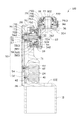
图2是图1所示机器人沿II-II线的剖视图。 Fig. 2 is a sectional view of the robot shown in Fig. 1 along line II-II.
主要元件符号说明 Description of main component symbols
如下具体实施方式将结合上述附图进一步说明本发明。 The following specific embodiments will further illustrate the present invention in conjunction with the above-mentioned drawings.
具体实施方式 Detailed ways
下面以具体实施方式并结合附图对本发明实施方式提供的机器人作进一步详细说明。 The robot provided in the embodiments of the present invention will be further described in detail below with reference to specific embodiments and drawings.
请参阅图1及图2,本发明实施方式的机器人100包括基座10、第一机械臂20、第二机械臂30、第一驱动件40、第一传动机构50、第二驱动件60、第二传动机构70及输出轴80。第一机械臂20固定在基座10上,第一机械臂20与第二机械臂30转动连接,第一机械臂20具有第一轴线22,第二机械臂30具有第二轴线32,且第一轴线22与第二轴线32基本垂直。第二机械臂30绕第二轴线32可相对第一机械臂20旋转,输出轴80与第二机械臂30转动连接。
1 and 2, the
基座10靠近第一机械臂20的一端开设有便于电缆、管线等通过的过线孔102。
An end of the
第一机械臂20为近似中空柱状,其包括收容部24、位于收容部24一端的第一连接端26及位于收容部24另一端的第二连接端28。收容部24用于收容第一驱动件40、第一传动机构50、第二驱动件60及部分第二传动机构70。第一连接端26与基座10固定连接,第二连接端28靠近第二机械臂30。
The first mechanical arm 20 is approximately hollow cylindrical and includes a receiving
第二机械臂30大体为L形,其包括固定端34及输出端36。固定端34靠近第一机械臂20的第二连接端28。固定端34大体沿垂直于第一轴线22的方向延伸。固定端34靠近第一机械臂20的一侧面凹设有收容槽342。输出端36自固定端34的一端沿垂直于第二轴线32的方向延伸。输出端36具有端面361,输出端36开设有以第二轴线32为轴线的贯穿端面361的过线孔362,本实施方式中,过线孔362与过线孔102同轴设置,以便于电缆、管线等通过。端面361上环绕过线孔362凹设有收容槽364。
The second mechanical arm 30 is substantially L-shaped, and includes a fixed
第一驱动件40收容于收容部24靠近第一连接端26的一端,第一驱动件40包括可旋转的驱动轴42。本发明实施方式中,第一驱动件40为电机。
The
第一传动机构50包括第一主动轮52、第一传动带54、第一从动轮56、传动件57、减速器58及连接件59。第一主动轮52套设并固定于驱动轴42上,可随驱动轴42同步转动。第一传动带54连接第一主动轮52及第一从动轮56,从而使得第一从动轮56可随第一主动轮52转动。传动件57收容于收容部24靠近第二连接端28的一端,第一从动轮56采用螺钉51固定于传动件57上。第一从动轮56及传动件57分别开设有沿第一轴线22方向延伸的轴孔562及轴孔572。
The
减速器58包括柔轮581及刚轮583。柔轮581套设于传动件57上并与传动件57固定连接,一个轴承585与刚轮583相邻套设于柔轮581上。柔轮581为圆筒状,其包括一个大致呈中空圆柱体状的容纳部(图未标)和形成于容纳部一端的凸缘5813。柔轮581的容纳部的外壁上远离凸缘5813的一端形成有第一轮齿(图未标)。柔轮581套设于传动件57上并与传动件57固定连接。轴承585套设于柔轮581的容纳部上,其外圈通过螺钉固定于柔轮581的凸缘5813上。刚轮583呈圆环状,刚轮583的内壁上形成有与柔轮581的第一轮齿相啮合的第二轮齿(图未标)。刚轮583套设于柔轮581远离凸缘5813的一端,并与轴承585相邻设置。刚轮583与轴承585的内圈通过螺钉固定,刚轮583的第二轮齿与柔轮581的第一轮齿相啮合。本实施方式中,第二轮齿的齿数大于第一轮齿的齿数。
The
连接件59通过位于连接件59和传动件57之间的轴承(图未标)套设于传动件57上。连接件59通过螺钉与刚轮583固定连接,第二机械臂30通过螺钉与连接件59固定连接。
The connecting
第二驱动件60收容于收容部24内且与第一驱动件40相邻设置,第二驱动件60包括可旋转的转轴62。本发明实施方式中,第二驱动件60为电机。
The
第二传动机构70包括第二主动轮71、传动轴72、第二从动轮73、第二传动带75、齿轮副76、传动件77及减速器79。
The
第二主动轮71套设并固定于转轴62上,可随转轴62同步转动。第二传动带75连接第二主动轮71及第二从动轮73,从而使得第二从动轮73可随第二主动轮71转动。传动轴72包括传动端722及与传动端722相对的固定端724。传动轴72穿设于传动件57的轴孔572及第一从动轮56的轴孔562,传动端722自第一从动轮56远离传动件57的一端突出。第二从动轮73套设并固定于传动轴72的传动端722。固定端724收容于收容槽342。
The second
本实施方式中,齿轮副76为锥齿轮副,其包括第一锥齿轮762及与第一锥齿轮762相啮合的第二锥齿轮764。传动件77呈套筒状,其开设有以第二轴线32为轴线过线孔772。第一锥齿轮762套设于传动轴72的固定端724并与传动轴72固定连接。第二锥齿轮764采用螺钉固定于传动件77的一端并与传动件77固定连接。
In this embodiment, the
减速器79与减速器58的结构相似,减速器79包括柔轮791及刚轮793。
The
柔轮791包括一个大致呈中空圆柱体状的容纳部(图未标)和形成于容纳部一端的凸缘7913。柔轮791的容纳部的外壁上形成有第一轮齿(图未标)。柔轮791套设于传动件77上并与传动件77止动连接。一个轴承795套设于柔轮791的容纳部上,其外圈通过螺钉固定于柔轮791的凸缘7913上。刚轮793呈圆环状,刚轮793的内壁上形成有与柔轮791的第一轮齿相啮合的第二轮齿(图未标)。刚轮793套设于柔轮791远离凸缘7913的一端,并与轴承795相邻设置。
The
输出轴80大致呈圆环状,其开设有以第二轴线32为轴线过线孔802。输出轴80用于连接夹具、焊接工具或喷涂工具等。输出轴80套设于传动件77上,并与刚轮793固定连接。刚轮793与轴承795的内圈通过螺钉固定,刚轮793的第二轮齿与柔轮791的第一轮齿相啮合。本实施方式中,第二轮齿的齿数较第一轮齿的齿数大。
The
使用时,将夹具、焊接工具或喷涂工具固定至输出轴80的末端。第一驱动件40带动第一主动轮52转动,并通过第一传动带54带动第一从动轮56转动。第一从动轮56带动固定于其上的传动件57相对第一机械臂20第一机械臂20转动,进而带动固定于传动件57上柔轮581转动,柔轮581带动刚轮583转动,刚轮583带动连接件59转动,连接件59带动第二机械臂30转动。
In use, a clamp, welding tool or spray tool is secured to the end of the
第二驱动件60带动第二主动轮71转动,并通过第二传动带75带动第二从动轮73转动。第二从动轮73带动与其固定连接的传动传动轴72相对第一机械臂20转动,进而带动固定于传动轴72上的第一锥齿轮762转动,第一锥齿轮762带动第二锥齿轮764转动,第二锥齿轮764带动传动件77相对第二机械臂30的转动,进而带动固定于传动件77上的柔轮791转动,柔轮791带动刚轮793转动,刚轮793带动输出轴80转动,输出轴80带动连接于其末端的夹具或其他机构。
The
本发明的机器人100的第一驱动件40设置于第一机械臂20的第一连接端26,第一传动机构50的减速器58设置于第一机械臂20的第二连接端28,降低了第一机械臂20的径向长度,提高了第一机械臂20的灵活性,第一驱动件40和减速器58分散设置,有利于驱动件及传动机构的散热,降低了机器人100的故障率。夹具、喷涂工具或焊接工具固定至输出轴80的末端,连接夹具、喷涂工具或焊接工具的电缆及管道依次通过过线孔102、过线孔362、过线孔772及过线孔802连接至夹具、喷涂工具或焊接工具,从而在夹具、喷涂工具或焊接工具随输出轴80绕第二轴线32转动时,电缆及管道处于转动中心而不会缠绕于第二机械臂30,增加了第二机械臂30转动的灵活性。
The
另外,本领域技术人员还可在本发明精神内做其它变化,当然,这些依据本发明精神所做的变化,都应包含在本发明所要求保护的范围内。 In addition, those skilled in the art can also make other changes within the spirit of the present invention. Of course, these changes made according to the spirit of the present invention should be included in the scope of protection claimed by the present invention.
Claims (10)
Priority Applications (3)
| Application Number | Priority Date | Filing Date | Title |
|---|---|---|---|
| CN201110297014.0A CN103029125B (en) | 2011-09-30 | 2011-09-30 | Robot |
| TW100137085A TWI461272B (en) | 2011-09-30 | 2011-10-13 | Robot |
| US13/488,584 US8910539B2 (en) | 2011-09-30 | 2012-06-05 | Robot with reducer |
Applications Claiming Priority (1)
| Application Number | Priority Date | Filing Date | Title |
|---|---|---|---|
| CN201110297014.0A CN103029125B (en) | 2011-09-30 | 2011-09-30 | Robot |
Publications (2)
| Publication Number | Publication Date |
|---|---|
| CN103029125A true CN103029125A (en) | 2013-04-10 |
| CN103029125B CN103029125B (en) | 2015-05-20 |
Family
ID=47991390
Family Applications (1)
| Application Number | Title | Priority Date | Filing Date |
|---|---|---|---|
| CN201110297014.0A Expired - Fee Related CN103029125B (en) | 2011-09-30 | 2011-09-30 | Robot |
Country Status (3)
| Country | Link |
|---|---|
| US (1) | US8910539B2 (en) |
| CN (1) | CN103029125B (en) |
| TW (1) | TWI461272B (en) |
Cited By (10)
| Publication number | Priority date | Publication date | Assignee | Title |
|---|---|---|---|---|
| CN103192369A (en) * | 2013-04-18 | 2013-07-10 | 岳强 | Novel waist rotating device of robot palletizer |
| CN103921284A (en) * | 2014-05-04 | 2014-07-16 | 南京信息工程大学 | Robot wrist driving mechanism |
| CN104511899A (en) * | 2013-09-27 | 2015-04-15 | 中日龙(襄阳)机电技术开发有限公司 | Biaxial numerical control electric posture portion mechanism |
| CN107363825A (en) * | 2017-08-25 | 2017-11-21 | 安徽大学 | Under-actuated 2R mechanical arm device based on harmonic deceleration |
| CN107414809A (en) * | 2017-06-20 | 2017-12-01 | 深圳市迈步机器人科技有限公司 | A kind of mechanical arm |
| CN107972021A (en) * | 2017-12-14 | 2018-05-01 | 杭州娃哈哈精密机械有限公司 | A kind of Multi-shaft mechanical arm |
| CN108161956A (en) * | 2017-11-30 | 2018-06-15 | 盛天誉 | Robot |
| CN109746904A (en) * | 2017-11-02 | 2019-05-14 | 精工爱普生株式会社 | Robots and Robotic Systems |
| CN110303519A (en) * | 2019-07-09 | 2019-10-08 | 郑州科技学院 | Wrist and Robot |
| CN117484481A (en) * | 2017-11-06 | 2024-02-02 | 精工爱普生株式会社 | robot |
Families Citing this family (16)
| Publication number | Priority date | Publication date | Assignee | Title |
|---|---|---|---|---|
| JP5423910B1 (en) * | 2013-01-17 | 2014-02-19 | 株式会社安川電機 | robot |
| JP6250372B2 (en) * | 2013-11-22 | 2017-12-20 | Ntn株式会社 | Automatic welding machine |
| USD781943S1 (en) * | 2014-04-11 | 2017-03-21 | Abb Gomtec Gmbh | Robotic arm component |
| DE102015200374A1 (en) * | 2015-01-13 | 2016-07-14 | Kuka Roboter Gmbh | Gearbox, electric drive device and industrial robot |
| EP3373836B1 (en) * | 2015-11-10 | 2023-01-04 | Eindhoven Medical Robotics B.V. | Modular robotic device for precision surgical bone removal and other applications |
| JP6426646B2 (en) * | 2016-03-23 | 2018-11-21 | ファナック株式会社 | Robot's wrist structure |
| USD890238S1 (en) * | 2018-03-02 | 2020-07-14 | Abb Schweiz Ag | Joint for an industrial robot |
| USD898090S1 (en) * | 2018-05-18 | 2020-10-06 | Universal Robots A/S | Toothed connection flange for a robot joint |
| USD895705S1 (en) * | 2018-05-18 | 2020-09-08 | Universal Robots A/S | Robot joint having an input flange, an output flange, and a top lid |
| US10856944B2 (en) * | 2018-11-05 | 2020-12-08 | Hiwin Technologies Corp. | Triaxial motion device |
| USD890829S1 (en) * | 2019-03-15 | 2020-07-21 | Misty Robotics, Inc. | Flange for a robotic arm |
| USD891494S1 (en) * | 2019-03-15 | 2020-07-28 | Misty Robotics, Inc. | Socket for a Robotic arm |
| JP7492925B2 (en) * | 2021-01-28 | 2024-05-30 | 川崎重工業株式会社 | Arm robot |
| TWM624165U (en) * | 2021-11-17 | 2022-03-01 | 正崴精密工業股份有限公司 | Motor control arm telescopic rotation and modularization |
| USD1082878S1 (en) * | 2022-01-14 | 2025-07-08 | Universal Robots A/S | Robot joint |
| USD1099187S1 (en) * | 2022-01-14 | 2025-10-21 | Universal Robots A/S | Robot joint |
Citations (6)
| Publication number | Priority date | Publication date | Assignee | Title |
|---|---|---|---|---|
| US20080034920A1 (en) * | 2006-08-10 | 2008-02-14 | Fanuc Ltd | Wrist driving structure for industrial robot |
| JP2008073833A (en) * | 2006-08-24 | 2008-04-03 | Fanuc Ltd | Drive mechanism for industrial robot arm |
| EP2230053A2 (en) * | 2009-03-16 | 2010-09-22 | Kabushiki Kaisha Yaskawa Denki | Industrial robot and control method |
| CN102069493A (en) * | 2009-11-19 | 2011-05-25 | 鸿富锦精密工业(深圳)有限公司 | Arm part of robot and robot |
| CN102267134A (en) * | 2011-07-12 | 2011-12-07 | 浙江万丰摩轮有限公司 | Multifunctional universal robot |
| CN102554922A (en) * | 2012-02-06 | 2012-07-11 | 北京联合大学 | Method for operating numerical-control manipulator with five degrees of freedom |
Family Cites Families (8)
| Publication number | Priority date | Publication date | Assignee | Title |
|---|---|---|---|---|
| US4671732A (en) * | 1982-11-19 | 1987-06-09 | American Cimflex Corporation | Industrial robot |
| GB2149707B (en) * | 1983-11-15 | 1987-10-28 | Hitachi Shipbuilding Eng Co | Automatic welding apparatus |
| DE3448409C2 (en) * | 1984-12-28 | 1993-01-28 | Kuka Schweissanlagen + Roboter Gmbh, 8900 Augsburg, De | Modular driving unit for industrial robot |
| DE20012444U1 (en) * | 2000-07-18 | 2001-08-23 | Kuka Roboter GmbH, 86165 Augsburg | Gear, especially for a robot |
| CN2625122Y (en) * | 2003-07-11 | 2004-07-14 | 张军辉 | Five-axial manipulator |
| JP4719010B2 (en) * | 2005-01-21 | 2011-07-06 | 日本電産サンキョー株式会社 | Industrial robot |
| JP4232795B2 (en) * | 2005-10-19 | 2009-03-04 | セイコーエプソン株式会社 | Parallel link mechanism and industrial robot |
| JP5457922B2 (en) * | 2010-04-14 | 2014-04-02 | 株式会社ダイヘン | Industrial robot |
-
2011
- 2011-09-30 CN CN201110297014.0A patent/CN103029125B/en not_active Expired - Fee Related
- 2011-10-13 TW TW100137085A patent/TWI461272B/en not_active IP Right Cessation
-
2012
- 2012-06-05 US US13/488,584 patent/US8910539B2/en active Active
Patent Citations (6)
| Publication number | Priority date | Publication date | Assignee | Title |
|---|---|---|---|---|
| US20080034920A1 (en) * | 2006-08-10 | 2008-02-14 | Fanuc Ltd | Wrist driving structure for industrial robot |
| JP2008073833A (en) * | 2006-08-24 | 2008-04-03 | Fanuc Ltd | Drive mechanism for industrial robot arm |
| EP2230053A2 (en) * | 2009-03-16 | 2010-09-22 | Kabushiki Kaisha Yaskawa Denki | Industrial robot and control method |
| CN102069493A (en) * | 2009-11-19 | 2011-05-25 | 鸿富锦精密工业(深圳)有限公司 | Arm part of robot and robot |
| CN102267134A (en) * | 2011-07-12 | 2011-12-07 | 浙江万丰摩轮有限公司 | Multifunctional universal robot |
| CN102554922A (en) * | 2012-02-06 | 2012-07-11 | 北京联合大学 | Method for operating numerical-control manipulator with five degrees of freedom |
Cited By (12)
| Publication number | Priority date | Publication date | Assignee | Title |
|---|---|---|---|---|
| CN103192369A (en) * | 2013-04-18 | 2013-07-10 | 岳强 | Novel waist rotating device of robot palletizer |
| CN104511899A (en) * | 2013-09-27 | 2015-04-15 | 中日龙(襄阳)机电技术开发有限公司 | Biaxial numerical control electric posture portion mechanism |
| CN103921284A (en) * | 2014-05-04 | 2014-07-16 | 南京信息工程大学 | Robot wrist driving mechanism |
| CN107414809A (en) * | 2017-06-20 | 2017-12-01 | 深圳市迈步机器人科技有限公司 | A kind of mechanical arm |
| CN107363825A (en) * | 2017-08-25 | 2017-11-21 | 安徽大学 | Under-actuated 2R mechanical arm device based on harmonic deceleration |
| CN107363825B (en) * | 2017-08-25 | 2020-07-07 | 安徽大学 | Under-actuated 2R mechanical arm device based on harmonic deceleration |
| CN109746904A (en) * | 2017-11-02 | 2019-05-14 | 精工爱普生株式会社 | Robots and Robotic Systems |
| CN117484481A (en) * | 2017-11-06 | 2024-02-02 | 精工爱普生株式会社 | robot |
| CN108161956A (en) * | 2017-11-30 | 2018-06-15 | 盛天誉 | Robot |
| CN108161956B (en) * | 2017-11-30 | 2020-02-21 | 盛天誉 | Robot |
| CN107972021A (en) * | 2017-12-14 | 2018-05-01 | 杭州娃哈哈精密机械有限公司 | A kind of Multi-shaft mechanical arm |
| CN110303519A (en) * | 2019-07-09 | 2019-10-08 | 郑州科技学院 | Wrist and Robot |
Also Published As
| Publication number | Publication date |
|---|---|
| CN103029125B (en) | 2015-05-20 |
| TWI461272B (en) | 2014-11-21 |
| TW201313419A (en) | 2013-04-01 |
| US8910539B2 (en) | 2014-12-16 |
| US20130081502A1 (en) | 2013-04-04 |
Similar Documents
| Publication | Publication Date | Title |
|---|---|---|
| CN103029125B (en) | Robot | |
| CN103101058B (en) | Robot arm | |
| CN102343592A (en) | Robot arm part | |
| TWI461273B (en) | Robot arm | |
| CN102398270B (en) | Robot arm part | |
| CN103101057B (en) | Robot arm | |
| CN102259337B (en) | Robot arm component | |
| CN102649276B (en) | Prosthetic robot wrist | |
| CN102990679B (en) | Flexbile gear operator guards and adopt the robot arm of this flexbile gear operator guards | |
| CN102452080A (en) | Robot arm component | |
| CN102441894A (en) | Arm component of robot | |
| CN102233585A (en) | Arm member of robot | |
| CN102198665A (en) | Arm part of robot | |
| TW201309441A (en) | Robot | |
| TW201501889A (en) | Robot arm assembly | |
| WO2022163789A1 (en) | Arm robot | |
| JP2014237206A (en) | Wrist driving structure part of industrial robot having degree of freedom of rotation triaxiality | |
| CN103659833B (en) | Robot arm | |
| US20130333509A1 (en) | Wrist configuration unit of industrial robot | |
| JP2019119042A (en) | Robot arm | |
| CN105150239B (en) | Hollow bias structure of wrist of industrial robot | |
| US9140332B2 (en) | Rational speed-reduction device | |
| RU2576285C2 (en) | Articulated robot wrist | |
| CN204954853U (en) | Industrial robot wrist cavity biasing structure | |
| CN103062566B (en) | Interpipe self-adaptive crawl mechanism |
Legal Events
| Date | Code | Title | Description |
|---|---|---|---|
| C06 | Publication | ||
| PB01 | Publication | ||
| C10 | Entry into substantive examination | ||
| SE01 | Entry into force of request for substantive examination | ||
| C14 | Grant of patent or utility model | ||
| GR01 | Patent grant | ||
| C41 | Transfer of patent application or patent right or utility model | ||
| TR01 | Transfer of patent right |
Effective date of registration: 20161216 Address after: Guangdong city of Shenzhen province Nanshan District Taoyuan Tong Lang Tianliao Industrial Zone A14 Building 2 floor Patentee after: Shenzhen Caina Semiconductor Equipment Co., Ltd. Address before: 518109 Guangdong city of Shenzhen province Baoan District Longhua Town Industrial Zone tabulaeformis tenth East Ring Road No. 2 two Patentee before: Hongfujin Precision Industry (Shenzhen) Co., Ltd. Patentee before: Honghai Precision Industry Co., Ltd. |
|
| CF01 | Termination of patent right due to non-payment of annual fee |
Granted publication date: 20150520 Termination date: 20190930 |
|
| CF01 | Termination of patent right due to non-payment of annual fee |