CN102843078A - Conversion device capable of integrating drive and low-voltage battery charging of switch reluctance motor - Google Patents

Conversion device capable of integrating drive and low-voltage battery charging of switch reluctance motor Download PDF

Info

Publication number
CN102843078A
CN102843078A CN2012102880670A CN201210288067A CN102843078A CN 102843078 A CN102843078 A CN 102843078A CN 2012102880670 A CN2012102880670 A CN 2012102880670A CN 201210288067 A CN201210288067 A CN 201210288067A CN 102843078 A CN102843078 A CN 102843078A
Authority
CN
China
Prior art keywords
module
low
drive
energy storage
reluctance motor
Prior art date
Legal status (The legal status is an assumption and is not a legal conclusion. Google has not performed a legal analysis and makes no representation as to the accuracy of the status listed.)
Pending
Application number
CN2012102880670A
Other languages
Chinese (zh)
Inventor
梁嘉宁
徐国卿
蹇林旎
李卫民
常明
王亮荣
Current Assignee (The listed assignees may be inaccurate. Google has not performed a legal analysis and makes no representation or warranty as to the accuracy of the list.)
Shenzhen Institute of Advanced Technology of CAS
Original Assignee
Shenzhen Institute of Advanced Technology of CAS
Priority date (The priority date is an assumption and is not a legal conclusion. Google has not performed a legal analysis and makes no representation as to the accuracy of the date listed.)
Filing date
Publication date
Application filed by Shenzhen Institute of Advanced Technology of CAS filed Critical Shenzhen Institute of Advanced Technology of CAS
Priority to CN2012102880670A priority Critical patent/CN102843078A/en
Publication of CN102843078A publication Critical patent/CN102843078A/en
Priority to PCT/CN2012/087909 priority patent/WO2014026460A1/en
Pending legal-status Critical Current

Links

Images

Classifications

    • BPERFORMING OPERATIONS; TRANSPORTING
    • B60VEHICLES IN GENERAL
    • B60LPROPULSION OF ELECTRICALLY-PROPELLED VEHICLES; SUPPLYING ELECTRIC POWER FOR AUXILIARY EQUIPMENT OF ELECTRICALLY-PROPELLED VEHICLES; ELECTRODYNAMIC BRAKE SYSTEMS FOR VEHICLES IN GENERAL; MAGNETIC SUSPENSION OR LEVITATION FOR VEHICLES; MONITORING OPERATING VARIABLES OF ELECTRICALLY-PROPELLED VEHICLES; ELECTRIC SAFETY DEVICES FOR ELECTRICALLY-PROPELLED VEHICLES
    • B60L15/00Methods, circuits, or devices for controlling the traction-motor speed of electrically-propelled vehicles
    • B60L15/007Physical arrangements or structures of drive train converters specially adapted for the propulsion motors of electric vehicles
    • BPERFORMING OPERATIONS; TRANSPORTING
    • B60VEHICLES IN GENERAL
    • B60LPROPULSION OF ELECTRICALLY-PROPELLED VEHICLES; SUPPLYING ELECTRIC POWER FOR AUXILIARY EQUIPMENT OF ELECTRICALLY-PROPELLED VEHICLES; ELECTRODYNAMIC BRAKE SYSTEMS FOR VEHICLES IN GENERAL; MAGNETIC SUSPENSION OR LEVITATION FOR VEHICLES; MONITORING OPERATING VARIABLES OF ELECTRICALLY-PROPELLED VEHICLES; ELECTRIC SAFETY DEVICES FOR ELECTRICALLY-PROPELLED VEHICLES
    • B60L50/00Electric propulsion with power supplied within the vehicle
    • B60L50/50Electric propulsion with power supplied within the vehicle using propulsion power supplied by batteries or fuel cells
    • B60L50/51Electric propulsion with power supplied within the vehicle using propulsion power supplied by batteries or fuel cells characterised by AC-motors
    • BPERFORMING OPERATIONS; TRANSPORTING
    • B60VEHICLES IN GENERAL
    • B60LPROPULSION OF ELECTRICALLY-PROPELLED VEHICLES; SUPPLYING ELECTRIC POWER FOR AUXILIARY EQUIPMENT OF ELECTRICALLY-PROPELLED VEHICLES; ELECTRODYNAMIC BRAKE SYSTEMS FOR VEHICLES IN GENERAL; MAGNETIC SUSPENSION OR LEVITATION FOR VEHICLES; MONITORING OPERATING VARIABLES OF ELECTRICALLY-PROPELLED VEHICLES; ELECTRIC SAFETY DEVICES FOR ELECTRICALLY-PROPELLED VEHICLES
    • B60L58/00Methods or circuit arrangements for monitoring or controlling batteries or fuel cells, specially adapted for electric vehicles
    • B60L58/10Methods or circuit arrangements for monitoring or controlling batteries or fuel cells, specially adapted for electric vehicles for monitoring or controlling batteries
    • B60L58/18Methods or circuit arrangements for monitoring or controlling batteries or fuel cells, specially adapted for electric vehicles for monitoring or controlling batteries of two or more battery modules
    • B60L58/20Methods or circuit arrangements for monitoring or controlling batteries or fuel cells, specially adapted for electric vehicles for monitoring or controlling batteries of two or more battery modules having different nominal voltages
    • BPERFORMING OPERATIONS; TRANSPORTING
    • B60VEHICLES IN GENERAL
    • B60LPROPULSION OF ELECTRICALLY-PROPELLED VEHICLES; SUPPLYING ELECTRIC POWER FOR AUXILIARY EQUIPMENT OF ELECTRICALLY-PROPELLED VEHICLES; ELECTRODYNAMIC BRAKE SYSTEMS FOR VEHICLES IN GENERAL; MAGNETIC SUSPENSION OR LEVITATION FOR VEHICLES; MONITORING OPERATING VARIABLES OF ELECTRICALLY-PROPELLED VEHICLES; ELECTRIC SAFETY DEVICES FOR ELECTRICALLY-PROPELLED VEHICLES
    • B60L58/00Methods or circuit arrangements for monitoring or controlling batteries or fuel cells, specially adapted for electric vehicles
    • B60L58/10Methods or circuit arrangements for monitoring or controlling batteries or fuel cells, specially adapted for electric vehicles for monitoring or controlling batteries
    • B60L58/18Methods or circuit arrangements for monitoring or controlling batteries or fuel cells, specially adapted for electric vehicles for monitoring or controlling batteries of two or more battery modules
    • B60L58/21Methods or circuit arrangements for monitoring or controlling batteries or fuel cells, specially adapted for electric vehicles for monitoring or controlling batteries of two or more battery modules having the same nominal voltage
    • HELECTRICITY
    • H02GENERATION; CONVERSION OR DISTRIBUTION OF ELECTRIC POWER
    • H02JELECTRIC POWER NETWORKS; CIRCUIT ARRANGEMENTS OR SYSTEMS FOR SUPPLYING OR DISTRIBUTING ELECTRIC POWER; SYSTEMS FOR STORING ELECTRIC ENERGY
    • H02J7/00Circuit arrangements for charging or discharging batteries or for supplying loads from batteries
    • H02J7/14Circuit arrangements for charging or discharging batteries or for supplying loads from batteries for charging batteries from dynamo-electric generators driven at varying speed, e.g. on vehicle
    • H02J7/16Regulation of the charging current or voltage by variation of field
    • H02J7/24Regulation of the charging current or voltage by variation of field using discharge tubes or semiconductor devices
    • BPERFORMING OPERATIONS; TRANSPORTING
    • B60VEHICLES IN GENERAL
    • B60LPROPULSION OF ELECTRICALLY-PROPELLED VEHICLES; SUPPLYING ELECTRIC POWER FOR AUXILIARY EQUIPMENT OF ELECTRICALLY-PROPELLED VEHICLES; ELECTRODYNAMIC BRAKE SYSTEMS FOR VEHICLES IN GENERAL; MAGNETIC SUSPENSION OR LEVITATION FOR VEHICLES; MONITORING OPERATING VARIABLES OF ELECTRICALLY-PROPELLED VEHICLES; ELECTRIC SAFETY DEVICES FOR ELECTRICALLY-PROPELLED VEHICLES
    • B60L2210/00Converter types
    • B60L2210/10DC to DC converters
    • B60L2210/12Buck converters
    • BPERFORMING OPERATIONS; TRANSPORTING
    • B60VEHICLES IN GENERAL
    • B60LPROPULSION OF ELECTRICALLY-PROPELLED VEHICLES; SUPPLYING ELECTRIC POWER FOR AUXILIARY EQUIPMENT OF ELECTRICALLY-PROPELLED VEHICLES; ELECTRODYNAMIC BRAKE SYSTEMS FOR VEHICLES IN GENERAL; MAGNETIC SUSPENSION OR LEVITATION FOR VEHICLES; MONITORING OPERATING VARIABLES OF ELECTRICALLY-PROPELLED VEHICLES; ELECTRIC SAFETY DEVICES FOR ELECTRICALLY-PROPELLED VEHICLES
    • B60L2210/00Converter types
    • B60L2210/10DC to DC converters
    • B60L2210/14Boost converters
    • BPERFORMING OPERATIONS; TRANSPORTING
    • B60VEHICLES IN GENERAL
    • B60LPROPULSION OF ELECTRICALLY-PROPELLED VEHICLES; SUPPLYING ELECTRIC POWER FOR AUXILIARY EQUIPMENT OF ELECTRICALLY-PROPELLED VEHICLES; ELECTRODYNAMIC BRAKE SYSTEMS FOR VEHICLES IN GENERAL; MAGNETIC SUSPENSION OR LEVITATION FOR VEHICLES; MONITORING OPERATING VARIABLES OF ELECTRICALLY-PROPELLED VEHICLES; ELECTRIC SAFETY DEVICES FOR ELECTRICALLY-PROPELLED VEHICLES
    • B60L2220/00Electrical machine types; Structures or applications thereof
    • B60L2220/10Electrical machine types
    • B60L2220/18Reluctance machines
    • HELECTRICITY
    • H02GENERATION; CONVERSION OR DISTRIBUTION OF ELECTRIC POWER
    • H02JELECTRIC POWER NETWORKS; CIRCUIT ARRANGEMENTS OR SYSTEMS FOR SUPPLYING OR DISTRIBUTING ELECTRIC POWER; SYSTEMS FOR STORING ELECTRIC ENERGY
    • H02J2105/00Networks for supplying or distributing electric power characterised by their spatial reach or by the load
    • H02J2105/30Networks for supplying or distributing electric power characterised by their spatial reach or by the load the load networks being external to vehicles, i.e. exchanging power with vehicles
    • HELECTRICITY
    • H02GENERATION; CONVERSION OR DISTRIBUTION OF ELECTRIC POWER
    • H02PCONTROL OR REGULATION OF ELECTRIC MOTORS, ELECTRIC GENERATORS OR DYNAMO-ELECTRIC CONVERTERS; CONTROLLING TRANSFORMERS, REACTORS OR CHOKE COILS
    • H02P25/00Arrangements or methods for the control of AC motors characterised by the kind of AC motor or by structural details
    • H02P25/02Arrangements or methods for the control of AC motors characterised by the kind of AC motor or by structural details characterised by the kind of motor
    • H02P25/08Reluctance motors
    • H02P25/092Converters specially adapted for controlling reluctance motors
    • YGENERAL TAGGING OF NEW TECHNOLOGICAL DEVELOPMENTS; GENERAL TAGGING OF CROSS-SECTIONAL TECHNOLOGIES SPANNING OVER SEVERAL SECTIONS OF THE IPC; TECHNICAL SUBJECTS COVERED BY FORMER USPC CROSS-REFERENCE ART COLLECTIONS [XRACs] AND DIGESTS
    • Y02TECHNOLOGIES OR APPLICATIONS FOR MITIGATION OR ADAPTATION AGAINST CLIMATE CHANGE
    • Y02TCLIMATE CHANGE MITIGATION TECHNOLOGIES RELATED TO TRANSPORTATION
    • Y02T10/00Road transport of goods or passengers
    • Y02T10/60Other road transportation technologies with climate change mitigation effect
    • Y02T10/64Electric machine technologies in electromobility
    • YGENERAL TAGGING OF NEW TECHNOLOGICAL DEVELOPMENTS; GENERAL TAGGING OF CROSS-SECTIONAL TECHNOLOGIES SPANNING OVER SEVERAL SECTIONS OF THE IPC; TECHNICAL SUBJECTS COVERED BY FORMER USPC CROSS-REFERENCE ART COLLECTIONS [XRACs] AND DIGESTS
    • Y02TECHNOLOGIES OR APPLICATIONS FOR MITIGATION OR ADAPTATION AGAINST CLIMATE CHANGE
    • Y02TCLIMATE CHANGE MITIGATION TECHNOLOGIES RELATED TO TRANSPORTATION
    • Y02T10/00Road transport of goods or passengers
    • Y02T10/60Other road transportation technologies with climate change mitigation effect
    • Y02T10/70Energy storage systems for electromobility, e.g. batteries
    • YGENERAL TAGGING OF NEW TECHNOLOGICAL DEVELOPMENTS; GENERAL TAGGING OF CROSS-SECTIONAL TECHNOLOGIES SPANNING OVER SEVERAL SECTIONS OF THE IPC; TECHNICAL SUBJECTS COVERED BY FORMER USPC CROSS-REFERENCE ART COLLECTIONS [XRACs] AND DIGESTS
    • Y02TECHNOLOGIES OR APPLICATIONS FOR MITIGATION OR ADAPTATION AGAINST CLIMATE CHANGE
    • Y02TCLIMATE CHANGE MITIGATION TECHNOLOGIES RELATED TO TRANSPORTATION
    • Y02T10/00Road transport of goods or passengers
    • Y02T10/60Other road transportation technologies with climate change mitigation effect
    • Y02T10/72Electric energy management in electromobility

Landscapes

  • Engineering & Computer Science (AREA)
  • Power Engineering (AREA)
  • Transportation (AREA)
  • Mechanical Engineering (AREA)
  • Life Sciences & Earth Sciences (AREA)
  • Sustainable Development (AREA)
  • Sustainable Energy (AREA)
  • Control Of Electric Motors In General (AREA)
  • Charge And Discharge Circuits For Batteries Or The Like (AREA)

Abstract

一种集成开关磁阻电机驱动与低压电池充电的变换装置,包括高压储能模块和与所述高压储能模块连接的驱动模块,以及与所述驱动模块连接的控制模块,还包括DC-DC变换模块,与所述控制模块和所述驱动模块连接;低压储能模块,存储有低压电能,向低压设备供电;所述控制模块根据预设程序控制所述驱动模块和所述低压储能模块工作;所述驱动模块驱动开关磁阻电机的运行,用于接收所述控制单元的指令驱动所述DC-DC变换模块,将高压储能模块的电能向所述低压储能模块充电。同时集成了开关磁阻电机驱动与低压电池充电的功能,不仅可以节省装置的空间,而且实现了器件的分时复用,大大减低了元件的成本和电路板布线的复杂性,使得其硬件结构更紧凑。

Figure 201210288067

A conversion device integrating switched reluctance motor drive and low-voltage battery charging, including a high-voltage energy storage module, a drive module connected to the high-voltage energy storage module, and a control module connected to the drive module, and also includes a DC-DC The conversion module is connected with the control module and the drive module; the low-voltage energy storage module stores low-voltage electric energy and supplies power to low-voltage equipment; the control module controls the drive module and the low-voltage energy storage module according to a preset program Work: the driving module drives the operation of the switched reluctance motor, and is used to receive the instruction of the control unit to drive the DC-DC conversion module, and charge the electric energy of the high-voltage energy storage module to the low-voltage energy storage module. At the same time, it integrates the functions of switched reluctance motor drive and low-voltage battery charging, which not only saves the space of the device, but also realizes time-division multiplexing of devices, which greatly reduces the cost of components and the complexity of circuit board wiring, making its hardware structure more compact.

Figure 201210288067

Description

A kind of integrated switch reluctance motor drives the converting means with the A-battery charging
Technical field
The present invention relates to a kind of switched reluctance machines drive system, specifically a kind of integrated switched reluctance machines drives and A-battery charging converting means.
Background technology
Switched reluctance machines is a kind of novel buncher, and governing system has direct current concurrently, exchanges the advantage of two types of governing systems, is the latest generation stepless time adjustment system of frequency conversion speed-adjusting system, brushless DC motor governing system of continuing.The drive circuit of switched reluctance machines in the prior art mainly comprises switching device, the switching device of bottom, the fly-wheel diode on top and the fly-wheel diode of bottom on DC power supply, dc capacitor, N phase motor windings, top.It is buffering to rectification circuit or battery to be provided that above-mentioned dc capacitor mainly acts on, the stable DC busbar voltage.N phase motor windings is parallel on the dc bus through switching device and fly-wheel diode.The above-mentioned upper switches device and the fly-wheel diode of bottom are connected to phase winding one end, and the above-mentioned lower device and the fly-wheel diode of bottom are connected to the other end of phase winding.
Above-mentioned switch reluctance machine driving circuit is widely used in family and the industry; But this circuit has only satisfied the demand of drive motors; For using frequent day by day electrical equipment (like robot, electric automobile, electronic weeder etc.), also need charge to accumulation power supply.Above-mentioned switch reluctance machine driving circuit can't satisfy the needs of charging.For this reason; Disclose a kind of integrated switch reluctance motor driving and charging converting means among the Chinese patent document CN201956913U, comprised energy-storage module and the driver module of connecting, also comprised rectification module with said energy-storage module; Be connected with electrical network, and be connected with said driver module; Control module; Be connected with said energy-storage module, said driver module unsteady flow module respectively; And control the rectification work of rectification module according to pre-set programs, and the control rectification module is to the charging of said energy-storage module, and control rectification module and energy-storage module are externally supplied power.In this technical scheme, the driving of charging module and switched reluctance machines is integrated together, realized charging to energy storage device.But this technical scheme only is applicable to AC power, particularly the incoming transport grid charging.Equipment according to inserting electrical network all will meet corresponding power factor requirement, and this scheme focuses on the charging control and the power factor controlling of high-tension battery.
For electric automobile, onboard charger can make the plug power taking of electric automobile from electrical network, and the storage battery of electric automobile is charged.Need a plurality of motor driven systems to satisfy the requirement of different loads (like tire, fan blade etc.) on the general electric automobile.At present, adopt double power-supply system in the electric automobile, a high tension battery that provides to the high drive machine operation, another provides the low tension battery to some low-voltage equipments in the car body.Because the A-battery capacity is lower; The general mode that adopts high-tension battery to give the A-battery electric energy supplement; Therefore in electric automobile, need be provided with one separately and convert high-tension electricity the equipment of low tension into, comprise driving arrangement or the like the electric component of DC-DC converter and charging.Like this, inner circuit and the electric equipment of electric automobile just becomes complicated.
Summary of the invention
Technical problem to be solved by this invention is that switched reluctance machines drives with the charging of DC power supply A-battery and uses the technical problem in specific installation, waste equipment and space in the prior art, so provide integrated switched reluctance machines drive the converting means that charges with the DC power supply A-battery.
In order to solve the problems of the technologies described above; The present invention provides a kind of integrated switch reluctance motor driving to comprise high-voltage energy storage module and the driver module that is connected with said high-voltage energy storage module with the converting means of A-battery charging; And the control module that is connected with said driver module; The operation of said driver module driving switch reluctance motor; Also comprise low pressure energy-storage module and the DC-DC conversion module that is connected with said low pressure energy-storage module; Said DC-DC conversion module is connected with said driver module with said control module, and said DC-DC conversion module is used for the electric energy of high-voltage energy storage module is charged to said low pressure energy-storage module, and said control module is controlled said driver module and the work of said DC-DC conversion module.
Converting means of the present invention, said driver module comprise at least two electronic power switches and at least two fly-wheel diodes, are used to receive the instruction driving of said control module; Said DC-DC conversion module comprises an electronic power switch and a diode.
Converting means of the present invention, said driver module comprise the half-bridge inverter of switched reluctance machines and the body of switched reluctance machines.
Converting means of the present invention, said DC-DC conversion module comprise rectification unit and the copped wave unit that is connected with said rectification unit.
Converting means of the present invention, said rectification unit is a rectifier, comprises a diode.
Converting means of the present invention; Said copped wave unit comprises a switching device; The negative pole of the diode of said rectification unit is connected with the collector electrode of said switching device; The emission collection of said switching device is connected with the positive pole of the A-battery of said low pressure energy-storage module, and the negative pole of said A-battery is connected with the negative pole of said high-tension battery.
Converting means of the present invention, said switching device are triode or relay, and when said switching device was relay, the negative pole of the diode of rectification unit connected with an end of relay, and the other end of relay connects with the A-battery group.
Converting means of the present invention, said converting means are that single-phase integrated switch reluctance motor drives and the converting means or the integrated switched reluctance machines of three-phase of A-battery drive and the A-battery converting means.
Converting means of the present invention; In the converting means of said single-phase integrated switch reluctance motor driving and A-battery; Said control module is digitial controller or microcomputerized controller; Said driver module is two electronic power switches and two fly-wheel diodes, and said electronic power switch is connected on the two ends of the winding of switched reluctance machines, and said two fly-wheel diodes are parallelly connected with winding and a described electronic power switch of said switched reluctance machines respectively; Said DC-DC conversion module is an electronic power switch and a diode, said electronic power switch and the series connection of said diode.
Converting means of the present invention; In the converting means of integrated switched reluctance machines driving of said three-phase and A-battery; Said driver module is six electronic power switches and six fly-wheel diodes, and after each electronic power switch was connected with each fly-wheel diode, parallel connection was arranged between the two poles of the earth of said high-voltage energy storage module; In two groups of adjacent parallel lines, the series sequence of said electronic power switch and fly-wheel diode is opposite; Each winding of said three phase electric machine is drawn at the central point of adjacent said parallel line; Said DC-DC conversion module is an electronic power switch and three diodes, said diode respectively with said windings in series after, be connected to the collector electrode of said electronic power switch.
Technique scheme of the present invention is compared prior art and is had the following advantages:
(1) integrated switch reluctance motor of the present invention drives the converting means that charges with A-battery; Comprise high-voltage energy storage module, driver module, control module, DC-DC conversion module and low pressure energy-storage module; Simultaneously integrated switched reluctance machines drives the function with the A-battery charging; Space that not only can economy system, driving electric electronic device, driving signal control circuit have simultaneously been realized the time-sharing multiplex of devices such as big electric capacity, inductance and heat abstractor; Lower the complexity of the cost and the circuit board wiring of element greatly, made its hardware configuration compacter.In addition, realized high efficiency intelligent battery charging, realized timely electric energy supplement according to the state of low pressure energy-storage module mesolow battery through control module, safe and reliable.
(2) integrated switch reluctance motor of the present invention drives the converting means that charges with A-battery; The high-voltage energy storage module stores has the high-tension battery group; The low pressure energy-storage module stores the A-battery group; Said driver module comprises the half-bridge inverter of switched reluctance machines and the body of switched reluctance machines, and said DC-DC converter module comprises rectification unit and the copped wave unit that is connected with said rectification unit, and described switched reluctance machines half-bridge inverter is made up of electronic power switch device and diode; Described rectification unit is made up of a diode, and described copped wave unit is made up of an electronic power switch device.This converting means is under drive pattern, and the energy of high-tension battery can pass through driver module, is converted into mechanical energy to electric energy.Under the A-battery charge mode, the energy of high-tension battery is transferred to voltage battery to the high-tension battery energy through driver module and DC-DC converter.The part of devices of driver module is participated in the energy conversion of two kinds of patterns simultaneously.
Description of drawings
For content of the present invention is more clearly understood, below in conjunction with accompanying drawing, the present invention is done further detailed explanation, wherein,
Fig. 1 drives the structured flowchart of the converting means that charges with A-battery for the integrated switch reluctance motor;
Fig. 2 is the circuit diagram that single-phase integrated switch reluctance motor drives the converting means that charges with A-battery;
Fig. 3 is the circuit diagram that the integrated switched reluctance machines of three-phase drives the converting means that charges with A-battery.
Embodiment
Below in conjunction with embodiment the present invention is done further description, but should be noted that these embodiment only are used to method of the present invention is described, and can not scope of the present invention be confined to this.
To do further description to the present invention through specific embodiment below.
Embodiment 1:
A kind of integrated switch reluctance motor drives the converting means with the A-battery charging; As shown in Figure 1, comprising: high-voltage energy storage module, driver module, control module, DC-DC conversion module and low pressure energy-storage module, wherein; Said high-voltage energy storage module is connected with said driver module; Said driver module is connected with the DC-DC conversion module, and said DC-DC module is connected with said low pressure energy-storage module, and said control module is connected respectively with said DC-DC conversion module with said driver module.This converting means has been realized the multiplexing of two kinds of functions that switched reluctance machines drives and the DC-DC converter charges.
Said high-voltage energy storage inside modules stores from the energy of electrical network or the generation of other generating equipments, is a jumbo high-voltage energy storage device, and said high-voltage energy storage module receives the control of battery management system.Said low pressure energy-storage module storage inside has low-voltage electric energy.Said DC-DC conversion module can charge the electric energy of said high-voltage energy storage module to the electric energy of said low pressure energy-storage module, this high-voltage energy storage module comprises an electronic power switch and a diode here.Said control module is controlled said driver module and the work of said DC-DC conversion module according to pre-set programs.The operation of said driver module driving switch reluctance motor; Comprise electronic power switch device and diode; Be used to receive the instruction driving of said control unit, the driver module part of devices is also participated in the energy conversion of the electric energy of high-voltage energy storage module to said low pressure energy-storage module.Said DC-DC conversion module charges the electric energy of high-voltage energy storage module to said low pressure energy-storage module, said controller is controlled said DC-DC conversion module action, realizes that the high-voltage energy storage module charges to said low pressure energy-storage module.The high-voltage energy storage module is as power supply, and controller module can read relevant information from the high-voltage energy storage module.
In the present embodiment, said high-voltage energy storage module comprises the high-voltage energy storage unit, and its storage inside has the high-tension battery group; Said low pressure energy-storage module comprises the low pressure energy-storage units, and its storage inside has the A-battery group.
Further, said driver module comprises the half-bridge inverter of switched reluctance machines and the body of switched reluctance machines.Said DC-DC converter module comprises rectification unit and the copped wave unit that is connected with said rectification unit.Said rectification unit is a rectifier, comprises a diode.Said copped wave unit comprises a switching device; The negative pole of the diode of said rectification unit is connected with the collector electrode of said switching device; The emission collection of said switching device is connected with the positive pole of the A-battery of said low pressure energy-storage module, and the negative pole of said A-battery is connected with the negative pole of said high-tension battery.The said switching device here is to be triode or relay, and when the switching device when here was relay, the negative pole of the diode of rectification unit connected with an end of relay, and the other end of relay connects with the A-battery group.
Providing single-phase integrated switch reluctance motor below respectively drives and the circuit of A-battery converting means and the circuit of integrated switched reluctance machines driving of three-phase and A-battery converting means.
Embodiment 2:
Single-phase integrated switch reluctance motor drives the circuit with the A-battery converting means, and is as shown in Figure 2.
Said high-voltage energy storage module comprises a high-tension battery group; Said driver module comprises electronic power switch device (Q1 and Q2) and semiconductor diode (D1 and D2); Said control module comprises digital processing unit or computer processor; Said DC-DC conversion module comprises electronic power switch device (Q3) and semiconductor diode (D3), and said low pressure energy-storage module comprises an A-battery group.Each module respectively with Fig. 2 in device corresponding.
In the present embodiment; In the converting means of said single-phase integrated switch reluctance motor driving and A-battery; Said control module is digitial controller or microcomputerized controller; Said driver module is two electronic power switches (Q1 and Q2) and two fly-wheel diodes (D1 and D2); Said electronic power switch is connected on the two ends of the winding (i.e. the first winding A) of switched reluctance machines, and said two sustained diode 1 are parallelly connected with winding and a described electronic power switch of said switched reluctance machines respectively with D2; Said DC-DC conversion module is an electronic power switch and a diode, said electronic power switch and the series connection of said diode.Particularly; The positive pole of said high-tension battery group is connected with the collector electrode of the said first switching device Q1; The emitter of the said first switching device Q1 is connected with the end of the first winding A; The other end of the said first winding A is connected with the collector electrode of said second switch device Q2, and is connected through first sustained diode 1 and said high-tension battery are anodal, and the positive pole of wherein said first sustained diode 1 is connected with the collector electrode of said second switch device Q2; The negative pole of said first sustained diode 1 is connected with the positive pole of said high-tension battery, and the emitter Q2 of said second switch device is connected with the negative pole of said high-tension battery; The positive pole of said second sustained diode 2 is connected with the negative pole of high-tension battery, and said second sustained diode, 2 negative poles are connected with the emitter of the first switching device Q1.Said DC-DC conversion module comprises rectification unit and the copped wave unit that is connected with said rectification unit.Said rectification unit is a rectifier, is the 3rd diode D3, and the positive pole of described the 3rd diode D3 is connected with the collector electrode of second switch device Q2.Said copped wave unit comprises the 3rd switching device Q3 at least, and the negative pole of described the 3rd diode D3 is connected with the collector electrode of the 3rd switching device Q3, and the emitter of said the 3rd switching device Q3 is connected with the positive pole of A-battery.The negative pole of described A-battery connects with the negative pole of high-tension battery.Said control module control can realize the driving operation of switched reluctance machines or the operation of buck DC-DC converter through controlling each switching device.When the 3rd switching device Q3 opened, the folding of the first switching device Q1 and second switch device Q2 was used for the operation of control switch reluctance motor.When second switch device Q2 opens, the electric current of the first switching device Q1 and the charging of the 3rd switching device Q3 Combination Control battery intelligent.Above-mentioned converting means can be realized the stepless time adjustment of motor and the intelligent charge of battery.
Embodiment 3:
The integrated switched reluctance machines of three-phase drives the circuit with the A-battery converting means, shown in Fig. 3.
Said high-voltage energy storage module comprises a high-tension battery group; Said driver module comprises electronic power switch device (Q1-Q6) and semiconductor diode (D1-D6); Said control module comprises digital processing unit or computer processor; Said DC-DC conversion module comprises electronic power switch device (Qz) and semiconductor diode (D7-D9), and said low pressure energy-storage module comprises an A-battery group.Each module respectively with Fig. 3 in device corresponding.
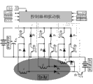
The integrated switched reluctance machines of three-phase drives the circuit diagram with A-battery charging converting means.Whole system is made up of electronic power switch device and power diode, electric capacity, storage battery, motor, electronic power switch device drive plate and controller.High tension battery and electric capacity are connected in parallel on the bus.
The negative pole of three electronic power switch device emitters and three power diodes composition brachium pontis that links together separately, the two ends of brachium pontis are connected on the bus simultaneously, and an end of three phase windings is connected to the central point of these brachium pontis separately.The positive pole of three electronic power switch device collector electrodes and three power diodes composition brachium pontis that links together separately, the two ends of brachium pontis are connected on the bus, and the other end of three phase windings is connected to the central point of these brachium pontis separately.The other end of three phase windings connects the positive pole of diode separately, and links together with the diode cathode of three phase windings connection, forms a tie point, and this tie point links to each other with the collector electrode of switching device Qz.The emitter of electronic power switch device Qz connects with A-battery is anodal, and the negative pole of A-battery is with the positive pole connection of high-tension battery.
Drive plate and controller are formed controller module, and it provides the control signal of electronic power switch device, and it also receives the signals such as electric current, voltage, rotor-position and temperature of whole system simultaneously.Controller module uses CAN communication to connect with entire car controller, and dtc signal, charging signals obtain from entire car controller.
Obviously, the foregoing description only be for explanation clearly done for example, and be not qualification to execution mode.For the those of ordinary skill in affiliated field, on the basis of above-mentioned explanation, can also make other multi-form variation or change.Here need not also can't give exhaustive to all execution modes.And conspicuous variation of being extended out thus or change still are among the protection range of the invention.

Claims (10)

1.一种集成开关磁阻电机驱动与低压电池充电的变换装置,包括高压储能模块和与所述高压储能模块连接的驱动模块,以及与所述驱动模块连接的控制模块,所述驱动模块驱动开关磁阻电机的运行,其特征在于,还包括低压储能模块和与所述低压储能模块连接的DC-DC变换模块,所述DC-DC变换模块与所述控制模块和所述驱动模块连接,所述DC-DC变换模块用于将高压储能模块的电能向所述低压储能模块充电,所述控制模块控制所述驱动模块和所述DC-DC变换模块工作。 1. A conversion device integrating switched reluctance motor drive and low-voltage battery charging, comprising a high-voltage energy storage module, a drive module connected to the high-voltage energy storage module, and a control module connected to the drive module, the drive The module drives the operation of the switched reluctance motor, and is characterized in that it also includes a low-voltage energy storage module and a DC-DC conversion module connected to the low-voltage energy storage module, and the DC-DC conversion module is connected with the control module and the The drive module is connected, the DC-DC conversion module is used to charge the electric energy of the high-voltage energy storage module to the low-voltage energy storage module, and the control module controls the operation of the drive module and the DC-DC conversion module. 2.根据权利要求1所述的变换装置,其特征在于:所述驱动模块包括至少两个电力电子开关和至少两个续流二极管,用于接收所述控制模块的指令驱动;所述DC-DC变换模块包括一个电力电子开关和一个二极管。 2. The conversion device according to claim 1, characterized in that: the driving module includes at least two power electronic switches and at least two freewheeling diodes for receiving instructions from the control module to drive; the DC- The DC conversion module includes a power electronic switch and a diode. 3.根据权利要求1或2所述的变换装置,其特征在于:所述驱动模块包括开关磁阻电机的半桥逆变器和开关磁阻电机的本体。 3. The conversion device according to claim 1 or 2, wherein the drive module comprises a half-bridge inverter of the switched reluctance motor and a body of the switched reluctance motor. 4.根据权利要求1-3中任一项所述的变换装置,其特征在于:所述DC-DC变换模块包括整流单元和与所述整流单元连接的斩波单元。 4. The conversion device according to any one of claims 1-3, wherein the DC-DC conversion module comprises a rectification unit and a chopping unit connected to the rectification unit. 5.根据权利要求4所述的变换装置,其特征在于:所述整流单元为整流器,包括一个二极管。 5. The conversion device according to claim 4, wherein the rectification unit is a rectifier comprising a diode. 6.根据权利要求4或5所述的变换装置,其特征在于:所述斩波单元包括一个开关器件,所述整流单元的二极管的负极与所述开关器件的集电极连接,所述开关器件的发射集与所述低压储能模块的低压电池的正极连接,所述低压电池的负极与所述高压电池的负极连接。 6. The conversion device according to claim 4 or 5, characterized in that: the chopping unit includes a switching device, the cathode of the diode of the rectifying unit is connected to the collector of the switching device, and the switching device The emission set of the low-voltage energy storage module is connected to the positive pole of the low-voltage battery, and the negative pole of the low-voltage battery is connected to the negative pole of the high-voltage battery. 7.根据权利要求6所述的变换装置,其特征在于,所述开关器件为三极管或继电器,当所述开关器件为继电器时,整流单元的二极管的负极跟继电器的一端连接,继电器的另一端跟低压电池组连接。 7. The conversion device according to claim 6, wherein the switching device is a triode or a relay, and when the switching device is a relay, the negative pole of the diode of the rectifying unit is connected to one end of the relay, and the other end of the relay is Connect with low voltage battery pack. 8.根据权利要求1-7中任一项所述的变换装置,其特征在于:所述变换装置为单相集成开关磁阻电机驱动与低压电池的变换装置或三相集成开关磁阻电机驱动与低压电池变换装置。 8. The conversion device according to any one of claims 1-7, characterized in that: the conversion device is a single-phase integrated switched reluctance motor drive and a low-voltage battery conversion device or a three-phase integrated switched reluctance motor drive With low voltage battery changer. 9.根据权利要求8所述的变换装置,其特征在于:所述单相集成开关磁阻电机驱动与低压电池的变换装置中,所述控制模块为数字控制器或微机控制器,所述驱动模块为两个电力电子开关和两个续流二极管,所述电力电子开关串联在开关磁阻电机的绕组的两端,所述两个续流二极管分别与所述开关磁阻电机的绕组和一个所述的电力电子开关并联;所述DC-DC变换模块为一个电力电子开关和一个二极管,所述电力电子开关和所述二极管串联。 9. The conversion device according to claim 8, characterized in that: in the conversion device of the single-phase integrated switched reluctance motor drive and low-voltage battery, the control module is a digital controller or a microcomputer controller, and the drive The modules are two power electronic switches and two freewheeling diodes, the power electronic switches are connected in series at both ends of the winding of the switched reluctance motor, and the two freewheeling diodes are respectively connected with the winding of the switched reluctance motor and a The power electronic switch is connected in parallel; the DC-DC conversion module is a power electronic switch and a diode, and the power electronic switch is connected in series with the diode. 10.根据权利要求8所述的变换装置,其特征在于:所述三相集成开关磁阻电机驱动与低压电池的变换装置中, 所述驱动模块为六个电力电子开关和六个续流二极管,每个电力电子开关和每个续流二极管串联后,并联设置在所述高压储能模块的两极之间,相邻的两组并联线路中,所述电力电子开关和续流二极管的串联顺序相反;所述三相电机的每个绕组在相邻的所述并联线路的中心点引出;所述DC-DC变换模块为一个电力电子开关和三个二极管,所述二极管分别与所述绕组串联后,连接到所述电力电子开关的集电极。 10. The conversion device according to claim 8, characterized in that: in the conversion device of the three-phase integrated switched reluctance motor drive and low-voltage battery, the drive module is six power electronic switches and six freewheeling diodes , after each power electronic switch and each freewheeling diode are connected in series, they are arranged in parallel between the two poles of the high-voltage energy storage module. In two adjacent groups of parallel circuits, the series sequence of the power electronic switch and freewheeling diode On the contrary; each winding of the three-phase motor is drawn at the center point of the adjacent parallel circuit; the DC-DC conversion module is a power electronic switch and three diodes, and the diodes are respectively connected in series with the windings After, connect to the collector of the power electronic switch.
CN2012102880670A 2012-08-14 2012-08-14 Conversion device capable of integrating drive and low-voltage battery charging of switch reluctance motor Pending CN102843078A (en)

Priority Applications (2)

Application Number Priority Date Filing Date Title
CN2012102880670A CN102843078A (en) 2012-08-14 2012-08-14 Conversion device capable of integrating drive and low-voltage battery charging of switch reluctance motor
PCT/CN2012/087909 WO2014026460A1 (en) 2012-08-14 2012-12-28 Conversion device integrated with switched reluctance motor drive and low-voltage battery charging

Applications Claiming Priority (1)

Application Number Priority Date Filing Date Title
CN2012102880670A CN102843078A (en) 2012-08-14 2012-08-14 Conversion device capable of integrating drive and low-voltage battery charging of switch reluctance motor

Publications (1)

Publication Number Publication Date
CN102843078A true CN102843078A (en) 2012-12-26

Family

ID=47370192

Family Applications (1)

Application Number Title Priority Date Filing Date
CN2012102880670A Pending CN102843078A (en) 2012-08-14 2012-08-14 Conversion device capable of integrating drive and low-voltage battery charging of switch reluctance motor

Country Status (2)

Country Link
CN (1) CN102843078A (en)
WO (1) WO2014026460A1 (en)

Cited By (11)

* Cited by examiner, † Cited by third party
Publication number Priority date Publication date Assignee Title
WO2014026460A1 (en) * 2012-08-14 2014-02-20 深圳先进技术研究院 Conversion device integrated with switched reluctance motor drive and low-voltage battery charging
CN103647483A (en) * 2013-12-13 2014-03-19 中国科学院深圳先进技术研究院 Power converting device integrated with switch magnetic resistance motor driving and cell charging
CN103647465A (en) * 2013-12-13 2014-03-19 中国科学院深圳先进技术研究院 Power converting device
CN104267757A (en) * 2014-09-11 2015-01-07 上海卫星工程研究所 High-altitude satellite heater electronic control system and method
CN105790587A (en) * 2016-05-31 2016-07-20 北京德尔福万源发动机管理系统有限公司 Inversion rectifier for hybrid power structure, hybrid power structure and control method of hybrid power structure
CN105914767A (en) * 2016-06-20 2016-08-31 杭州杰能动力有限公司沈阳分公司 Electric automobile drive and electric energy conversion control method
CN109936234A (en) * 2017-12-15 2019-06-25 中华汽车工业股份有限公司 The motor for automobile of built-in charging control function
CN110341517A (en) * 2019-06-06 2019-10-18 深圳先进技术研究院 A kind of electric energy bi-directional conversion device, electric vehicle and electric vehicle power supply system
CN113131803A (en) * 2021-04-21 2021-07-16 郑州大学 Low-cost power converter for switched reluctance motor and control strategy thereof
CN115065128A (en) * 2022-07-26 2022-09-16 荣耀终端有限公司 Electronic device and charging control method
CN115395631A (en) * 2022-07-07 2022-11-25 中国矿业大学 Photovoltaic power supply assisted switch reluctance motor hybrid power driving system

Citations (3)

* Cited by examiner, † Cited by third party
Publication number Priority date Publication date Assignee Title
US6137256A (en) * 1998-11-10 2000-10-24 Tridelta Industries, Inc. Soft turn-off controller for switched reluctance machines
CN1356766A (en) * 2000-11-23 2002-07-03 开关磁阻驱动有限公司 Operation of switch magnetoresistance drive system using double voltage source
CN201956913U (en) * 2011-04-21 2011-08-31 中国科学院深圳先进技术研究院 Integral switched reluctance motor drive and charging governing device

Family Cites Families (3)

* Cited by examiner, † Cited by third party
Publication number Priority date Publication date Assignee Title
US8466652B2 (en) * 2011-01-12 2013-06-18 Arvinmeritor Technology, Llc Method and apparatus for generating a charging circuit
CN102611269B (en) * 2012-04-01 2014-03-12 浙江大学 Switched reluctance motor powered by new energy
CN102843078A (en) * 2012-08-14 2012-12-26 深圳先进技术研究院 Conversion device capable of integrating drive and low-voltage battery charging of switch reluctance motor

Patent Citations (3)

* Cited by examiner, † Cited by third party
Publication number Priority date Publication date Assignee Title
US6137256A (en) * 1998-11-10 2000-10-24 Tridelta Industries, Inc. Soft turn-off controller for switched reluctance machines
CN1356766A (en) * 2000-11-23 2002-07-03 开关磁阻驱动有限公司 Operation of switch magnetoresistance drive system using double voltage source
CN201956913U (en) * 2011-04-21 2011-08-31 中国科学院深圳先进技术研究院 Integral switched reluctance motor drive and charging governing device

Cited By (15)

* Cited by examiner, † Cited by third party
Publication number Priority date Publication date Assignee Title
WO2014026460A1 (en) * 2012-08-14 2014-02-20 深圳先进技术研究院 Conversion device integrated with switched reluctance motor drive and low-voltage battery charging
CN103647465B (en) * 2013-12-13 2016-08-17 中国科学院深圳先进技术研究院 A kind of power conversion unit
CN103647483A (en) * 2013-12-13 2014-03-19 中国科学院深圳先进技术研究院 Power converting device integrated with switch magnetic resistance motor driving and cell charging
CN103647465A (en) * 2013-12-13 2014-03-19 中国科学院深圳先进技术研究院 Power converting device
CN103647483B (en) * 2013-12-13 2016-04-06 中国科学院深圳先进技术研究院 The power conversion unit that a kind of switch reluctance motor drives and battery charges
CN104267757A (en) * 2014-09-11 2015-01-07 上海卫星工程研究所 High-altitude satellite heater electronic control system and method
CN105790587A (en) * 2016-05-31 2016-07-20 北京德尔福万源发动机管理系统有限公司 Inversion rectifier for hybrid power structure, hybrid power structure and control method of hybrid power structure
CN105914767A (en) * 2016-06-20 2016-08-31 杭州杰能动力有限公司沈阳分公司 Electric automobile drive and electric energy conversion control method
CN105914767B (en) * 2016-06-20 2018-06-29 杭州杰能动力有限公司沈阳分公司 A kind of electric automobile driving apparatus and transformation of electrical energy control method
CN109936234A (en) * 2017-12-15 2019-06-25 中华汽车工业股份有限公司 The motor for automobile of built-in charging control function
CN110341517A (en) * 2019-06-06 2019-10-18 深圳先进技术研究院 A kind of electric energy bi-directional conversion device, electric vehicle and electric vehicle power supply system
CN113131803A (en) * 2021-04-21 2021-07-16 郑州大学 Low-cost power converter for switched reluctance motor and control strategy thereof
CN115395631A (en) * 2022-07-07 2022-11-25 中国矿业大学 Photovoltaic power supply assisted switch reluctance motor hybrid power driving system
CN115065128A (en) * 2022-07-26 2022-09-16 荣耀终端有限公司 Electronic device and charging control method
CN115065128B (en) * 2022-07-26 2023-01-17 荣耀终端有限公司 Electronic device and charging control method

Also Published As

Publication number Publication date
WO2014026460A1 (en) 2014-02-20

Similar Documents

Publication Publication Date Title
CN102843078A (en) Conversion device capable of integrating drive and low-voltage battery charging of switch reluctance motor
CN102826054B (en) Multi-functional integrated power electronic system of electric automobile
CN103647483B (en) The power conversion unit that a kind of switch reluctance motor drives and battery charges
US7830036B2 (en) Power electronic module pre-charge system and method
CN209479443U (en) A kind of battery heating system
US9231404B2 (en) Energy storage device, system with energy storage device and method for driving an energy storage device
CN101425771B (en) Control circuit, braking method, energy production method and device for DC motor
CN202444440U (en) Bridgeless inverter circuit and solar bridgeless inverter
US20180254732A1 (en) A controller for an inductive load having one or more inductive windings
CN103647465B (en) A kind of power conversion unit
CN203708154U (en) Power conversion device integrating switch reluctance motor driving and battery charging
EP2983282A2 (en) Three port dc-dc converter
CN101325381B (en) Two-source inverter
CN101355320A (en) Voltage link control of a dc-ac boosting converter system
US9825470B2 (en) Multi-source power converter
CN104620492B (en) Method and energy supply system for the coupling device that controls energy storing device
US12255529B2 (en) Power factor correction and DC-DC multiplexing converter and uninterruptible power supply including the same
KR20130078106A (en) Electric vehicle charging device
US8203236B2 (en) Dual voltage-source inverter system and method
US7719138B2 (en) Two-source series inverter
EP4262042A1 (en) Energy storage system
CN203708127U (en) Power conversion device
CN104716680A (en) Offline uninterruptible power supply with renewable energy and control method thereof
CN216215912U (en) Inverter and auxiliary power supply circuit thereof
CN201956913U (en) Integral switched reluctance motor drive and charging governing device

Legal Events

Date Code Title Description
C06 Publication
PB01 Publication
C10 Entry into substantive examination
SE01 Entry into force of request for substantive examination
C12 Rejection of a patent application after its publication
RJ01 Rejection of invention patent application after publication

Application publication date: 20121226