CN102774365A - Intelligent handbrake device and control method - Google Patents
Intelligent handbrake device and control method Download PDFInfo
- Publication number
- CN102774365A CN102774365A CN2012101720265A CN201210172026A CN102774365A CN 102774365 A CN102774365 A CN 102774365A CN 2012101720265 A CN2012101720265 A CN 2012101720265A CN 201210172026 A CN201210172026 A CN 201210172026A CN 102774365 A CN102774365 A CN 102774365A
- Authority
- CN
- China
- Prior art keywords
- motor
- control unit
- gear
- electronic control
- signal
- Prior art date
- Legal status (The legal status is an assumption and is not a legal conclusion. Google has not performed a legal analysis and makes no representation as to the accuracy of the status listed.)
- Granted
Links
Images




Landscapes
- Braking Arrangements (AREA)
- Regulating Braking Force (AREA)
- Braking Systems And Boosters (AREA)
Abstract
Description
技术领域 technical field
本发明涉及智能手刹装置,特别是一种汽车智能手刹装置。The invention relates to an intelligent handbrake device, in particular to an automobile intelligent handbrake device.
背景技术 Background technique
汽车制动系统主要分为行车制动系统及驻车制动系统,行车制动指在车辆行进过程中用于实施车辆制动的系统。驻车制动主要在车辆停止后用于车辆长期稳定停车的系统,又称为手刹。The automobile brake system is mainly divided into a service brake system and a parking brake system. The service brake refers to the system used to implement the vehicle brake during the driving process of the vehicle. The parking brake is mainly used for the long-term stable parking system of the vehicle after the vehicle stops, also known as the hand brake.
目前大部分车型的手刹都采用人力拉动手刹拉杆实施驻车制动,在手刹拉动过程中,驾驶员往往根据经验、手感来实施车辆在不同坡道情况下的驻车制动力,或者直接将手刹拉杆拉至最大行程,因而驻车制动大小存在人为的不确定性,驾驶员实施的拉力大小直接影响驻车的安全性及部件的过度使用,从而影响部件的疲劳寿命。At present, the handbrake of most models adopts the manual pull of the handbrake lever to implement the parking brake. During the process of pulling the handbrake, the driver often implements the parking brake force of the vehicle on different slopes according to experience and hand feeling, or directly applies the handbrake. The pull rod is pulled to the maximum stroke, so there is artificial uncertainty in the size of the parking brake. The pulling force applied by the driver directly affects the safety of parking and the overuse of components, thereby affecting the fatigue life of the components.
在坡道起步过程中也需手刹配合方能使车辆正常行驶,且过程繁琐,常因操作生疏引发溜坡乃至熄火等情况,存在安全隐患。In the process of starting on a slope, the cooperation of the handbrake is also required to make the vehicle run normally, and the process is cumbersome, and the situation of slipping down the slope or even stalling due to erratic operation often causes potential safety hazards.
发明内容 Contents of the invention
本发明所要解决的技术问题就是提供一种智能手刹装置,能根据路面坡道角度、车辆行进角度自动计算车辆所需驻车制动力大小。The technical problem to be solved by the present invention is to provide an intelligent hand brake device, which can automatically calculate the parking brake force required by the vehicle according to the slope angle of the road surface and the driving angle of the vehicle.
为解决上述技术问题,本发明采用如下技术方案:一种智能手刹装置,包括箱体及设于箱体内的拉紧机构,所述拉紧机构后端连接车辆制动拉线,其特征在于:所述拉紧机构前端由电机驱动拉紧及松开车辆制动拉线,所述电机由电控单元控制,所述拉紧机构后端设置一限位开关,限位开关与电控单元连接,所述电控单元根据采集的电机转速信号、车辆倾角信号、制动拉线位移信号、制动卡钳的蹄片温度信号及限位开关信号控制电机的转动以实施或者解除驻车。In order to solve the above-mentioned technical problems, the present invention adopts the following technical solutions: an intelligent handbrake device, including a box body and a tensioning mechanism arranged in the box body, the rear end of the tensioning mechanism is connected to a vehicle brake cable, which is characterized in that: The front end of the tensioning mechanism is driven by a motor to tighten and loosen the vehicle brake cable. The motor is controlled by an electronic control unit. A limit switch is arranged at the rear end of the tensioning mechanism. The electronic control unit controls the rotation of the motor according to the collected motor speed signal, vehicle inclination signal, brake cable displacement signal, brake caliper shoe temperature signal and limit switch signal to implement or release parking.
作为优选,所述拉紧机构包括齿轮变速机构及丝杠螺母机构,电机输出轴连接齿轮变速机构,齿轮变速机构的输出齿轮与丝杠螺母机构中的丝杠固定,丝杠螺母机构中的丝杠螺母连接车辆制动拉线。Preferably, the tensioning mechanism includes a gear transmission mechanism and a lead screw nut mechanism, the output shaft of the motor is connected to the gear transmission mechanism, the output gear of the gear transmission mechanism is fixed to the lead screw in the lead screw nut mechanism, and the screw in the lead screw nut mechanism The lever nut is connected to the vehicle brake cable.
作为优选,所述齿轮变速机构包括安装于电机输出轴上的电机齿轮及一双联齿轮,双联齿轮设于一双联齿轮轴上,双联齿轮由一大齿轮和一小齿轮组成,大齿轮与电机齿轮啮合,小齿轮与一丝杠齿轮啮合。As a preference, the gear transmission mechanism includes a motor gear mounted on the output shaft of the motor and a double gear, the double gear is arranged on a double gear shaft, the double gear is composed of a large gear and a small gear, the large gear and the The motor gear meshes, and the pinion gear meshes with the lead screw gear.
作为优选,所述丝杠螺母机构包括一丝杠及与丝杠配合的丝杠螺母,所述丝杆齿轮安装于丝杠上,所述丝杠螺母设于一螺母导向套内,螺母导向套底部设有一弹簧,丝杆螺母套入螺母导向套并将顶压弹簧,丝杆螺母顶端的导向块嵌入螺母导向套顶端的导向槽内,丝杠螺母与一拉索固定座紧固,拉索固定座末端设置制动拉线挂槽以连接车辆制动拉线。Preferably, the screw nut mechanism includes a lead screw and a lead screw nut matched with the lead screw, the lead screw gear is installed on the lead screw, the lead screw nut is arranged in a nut guide sleeve, and the bottom of the nut guide sleeve There is a spring, the screw nut is inserted into the nut guide sleeve and pressed against the spring, the guide block at the top of the screw nut is embedded in the guide groove at the top of the nut guide sleeve, the screw nut is fastened with a cable fixing seat, and the cable is fixed A brake cable hanging slot is provided at the end of the seat to connect the vehicle brake cable.
作为优选,所述丝杆前端穿过箱体的前端盖,前端盖内设有端面轴承支撑丝杠,一锁紧螺母与丝杆前端螺纹连接紧固,且锁紧螺母内端面压紧端面轴承外端面,丝杆转动过程中,锁紧螺母压迫端面轴承并随丝杆做旋转运动。As a preference, the front end of the screw rod passes through the front end cover of the box, and the front end cover is provided with an end face bearing to support the lead screw, and a lock nut is threadedly connected to the front end of the screw rod for fastening, and the inner end face of the lock nut is pressed against the end face bearing On the outer end face, during the rotation of the screw rod, the lock nut compresses the bearing on the end face and rotates with the screw rod.
作为优选,所述双联齿轮轴穿出箱体前端盖,双联齿轮轴端面上加工有与六角扳手配合的六方沉台。As a preference, the double gear shaft passes through the front end cover of the box body, and a hexagonal sink for matching with a hexagonal wrench is processed on the end surface of the double gear shaft.
作为优选,所述电控单元为一单片机,所述单片机与采集电机转速信号的电机转速传感器、采集车辆倾角信号的车辆倾角传感器、采集制动卡钳蹄片温度信号的温度传感器及采集车辆制动拉线位移的位移传感器连接。Preferably, the electronic control unit is a single-chip microcomputer, and the single-chip microcomputer is connected with a motor speed sensor for collecting motor speed signals, a vehicle inclination sensor for collecting vehicle inclination signals, a temperature sensor for collecting brake caliper shoe temperature signals, and a vehicle brake sensor for collecting vehicle braking signals. Displacement sensor connection for guy wire displacement.
作为优选,所述位移传感器挂扣于丝杆螺母底部,所述位移传感器随丝杆螺母同步作直线运动并监测位移信号。Preferably, the displacement sensor is hooked to the bottom of the screw nut, and the displacement sensor moves linearly with the screw nut synchronously and monitors the displacement signal.
本发明还提供了上述智能手刹装置的控制方法:其特征在于:The present invention also provides a control method for the above-mentioned intelligent handbrake device: it is characterized in that:
电控单元控制实施驻车包括如下步骤;首先,电控单元根据车辆倾角信号计算所需驻车力并控制电机正转,其次,电控单元根据电机转速信号做出控制,如果电机反转,电控单元控制电机停转,如果电机正转,电控单元根据制动拉线位移信号及制动卡钳的蹄片温度信号调整所需驻车力并控制电机转动,最后,如果达到所需驻车力,电控单元控制电机停止转动,制动过程结束,如果达不到所需驻车力,继续实施驻车制动;The electronic control unit controls the implementation of parking including the following steps: first, the electronic control unit calculates the required parking force according to the vehicle inclination angle signal and controls the motor to rotate forward; secondly, the electronic control unit performs control according to the motor speed signal. The electronic control unit controls the motor to stop. If the motor rotates forward, the electronic control unit adjusts the required parking force and controls the rotation of the motor according to the brake cable displacement signal and the shoe temperature signal of the brake caliper. Finally, if the required parking force is reached The electric control unit controls the motor to stop rotating, and the braking process ends. If the required parking force cannot be reached, the parking brake will continue to be applied;
电控单元控制解除驻车包括如下步骤;首先,电控单元控制电机反转,其次,电控单元根据电机转速信号做出控制,如果电机正转,电控单元控制电机停转,如果电机反转,电控单元根据制动拉线位移信号计算所需驻车力并控制电机转动,最后,如果限位开关闭合,电控单元控制电机停止转动,如果限位开关尚未闭合需要判断是否达到所需的解锁门限,如果达到解锁门限,电机继续反转设定的圈数后电机停止转动,制动过程结束。The electronic control unit control to release the parking includes the following steps: first, the electronic control unit controls the motor to reverse, and secondly, the electronic control unit controls according to the motor speed signal. If the motor is rotating forward, the electronic control unit controls the motor to stop. Turn, the electronic control unit calculates the required parking force according to the displacement signal of the brake cable and controls the rotation of the motor. Finally, if the limit switch is closed, the electronic control unit controls the motor to stop rotating. If the limit switch is not closed, it needs to judge whether the required If the unlocking threshold is reached, the motor will continue to reverse for the set number of turns, and then the motor will stop rotating, and the braking process will end.
本发明中拉紧机构由电机驱动拉紧车辆制动拉线,电机的电控单元根据采集的电机转速信号、车辆倾角信号及驻车制动力信号、限位开关信号及制动卡钳的蹄片温度信号控制电机的转动,通过电机的正反转可以实现实施或者解除驻车,因而能根据路面坡道角度、车辆行进角度,自动计算车辆所需驻车制动力大小,还能针对制动蹄片温度变化作出温度补偿,进而实施合适的驻车制动,实现了在全智能模式下根据驾驶员意图智能实施/解除驻车。In the present invention, the tightening mechanism is driven by a motor to tighten the brake cable of the vehicle. The electronic control unit of the motor is based on the collected motor speed signal, vehicle inclination angle signal, parking brake force signal, limit switch signal and shoe temperature of the brake caliper. The signal controls the rotation of the motor, and the parking can be implemented or released through the positive and negative rotation of the motor. Therefore, it can automatically calculate the parking brake force required by the vehicle according to the slope angle of the road surface and the driving angle of the vehicle, and can also target the brake shoe. Temperature compensation is made for temperature changes, and then the appropriate parking brake is implemented, realizing the intelligent implementation/release of parking according to the driver's intention in the full intelligent mode.
附图说明 Description of drawings
下面结合附图和具体实施方式对本发明作进一步描述:The present invention will be further described below in conjunction with accompanying drawing and specific embodiment:
图1为本专利结构总成爆炸图;Fig. 1 is the exploded diagram of this patent structure assembly;
图2为本专利齿轮-丝杆传动爆炸图;Fig. 2 is the explosion diagram of the gear-screw drive of the patent;
图3为本专利前端盖组件带丝杆爆炸图;Fig. 3 is the exploded view of the front end cover assembly with screw rod of this patent;
图4为本专利拉紧机构爆炸图;Figure 4 is an exploded view of the tensioning mechanism of the patent;
图5为本专利手动解锁主视图;Fig. 5 is the front view of manual unlocking of this patent;
图6为电动驻车制动装置结构框图,其中实线框内为装置的总成,外面为与其相连接的零部件;Figure 6 is a structural block diagram of the electric parking brake device, in which the assembly of the device is inside the solid line frame, and the parts connected to it are outside;
图7为电动驻车制动装置的电路原理框图;Fig. 7 is a circuit principle block diagram of the electric parking brake device;
图8A为控制电路X的电机驱动电路的电机正反转控制部分的原理图;8A is a schematic diagram of the motor forward and reverse control part of the motor drive circuit of the control circuit X;
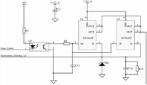
图8B为控制电路X的电机驱动电路的电机回路电流检测部分和电机续流控制电路部分的原理图;8B is a schematic diagram of the motor loop current detection part and the motor freewheeling control circuit part of the motor drive circuit of the control circuit X;
图8C为控制电路X的倾角传感器检测电路的原理图;8C is a schematic diagram of the detection circuit of the inclination sensor of the control circuit X;
图8D为控制电路X的拉力霍尔传感器检测电路的原理图;FIG. 8D is a schematic diagram of a pull Hall sensor detection circuit of the control circuit X;
图8E为控制电路X的温度检测电路检测电路的原理图;8E is a schematic diagram of the temperature detection circuit detection circuit of the control circuit X;
图9为驻车制动逻辑框图;Fig. 9 is a logical block diagram of the parking brake;
图10为解除驻车制动逻辑框图。Fig. 10 is a logical block diagram of releasing the parking brake.
具体实施方式 Detailed ways
首先,参考图1至图6具体说明本发明智能手刹装置的机械结构,First, the mechanical structure of the intelligent handbrake device of the present invention will be described in detail with reference to FIGS. 1 to 6,
如图1所示,该种智能手刹装置包括:1拉紧机构、2上端盖、3电控单元、4电机、5丝杠齿轮、6双联齿轮、7前端盖、8滑动轴承、9轴承、10箱体、11丝杆、12限位开关、13后端盖。该装置为机电耦合产品,结构紧凑,性能稳定,功能全面,能有效简化驾驶员操作,并提高整车优越性。As shown in Figure 1, this kind of intelligent handbrake device includes: 1 tensioning mechanism, 2 upper end cover, 3 electronic control unit, 4 motor, 5 screw gear, 6 double gear, 7 front end cover, 8 sliding bearing, 9 bearing , 10 box, 11 screw, 12 limit switch, 13 rear end cover. The device is an electromechanical coupling product with compact structure, stable performance and comprehensive functions, which can effectively simplify the driver's operation and improve the superiority of the vehicle.
具体的,电机4通过螺栓与箱体10紧固;双联齿轮6通过滑动轴承8安装于箱体10齿轮箱内,并与丝杠齿轮5啮合;丝杠齿轮5通过轴承9安装于箱体10齿轮箱内,并与双联齿轮6啮合;丝杆11与丝杠齿轮5通过键固定;前端盖7通过螺栓与箱体10紧固连接,连接端面设置端面密封圈;电控单元3通过螺栓与上端盖2紧固连接,且上端盖2与箱体10通过螺栓紧固,并于连接端面设置端面密封圈;拉紧机构1内置丝杆螺母1c与丝杆11啮合传动作直线运动,拉紧机构1后端挂槽可挂扣车辆制动拉线。Specifically, the
如图2所示,电机齿轮42与电机前端输出轴41连接,传递转矩,电机转速传感器43与电机输出轴41末端相连;电机齿轮42与双联齿轮6中大齿轮啮合,并带动双联齿轮转动;双联齿轮小齿轮与丝杠齿轮5啮合,并随双联齿轮转动;丝杠齿轮5内径设置键槽,丝杆11通过键14与丝杠齿轮连接,并随双联齿轮转动;拉紧机构1内置丝杆螺母1c与丝杆11啮合,并在箱体10内导向槽内滑动做直线位移,拉紧机构设置制动拉线挂槽可挂扣车辆制动拉线;限位开关12通过螺栓安装于箱体10内,并布置于拉紧机构1末端。As shown in Figure 2, the motor gear 42 is connected to the output shaft 41 at the front end of the motor to transmit torque, and the motor speed sensor 43 is connected to the end of the motor output shaft 41; the motor gear 42 meshes with the large gear in the
如图3所示,丝杆前端穿过前端盖74,并与端面轴承73相连接,锁紧螺母72与丝杆11前端螺纹连接紧固,且其端面压迫于端面轴承73端面,丝杆11转动过程中,锁紧螺母72压迫端面轴承73并随丝杆做旋转运动,前端盖盖板71通过螺栓与前端盖74紧固连接,密封相应组件,并限制丝杆11做直线运动。As shown in Figure 3, the front end of the screw rod passes through the
如图4所示,储能装置1b安装与螺母导向套1a内,储能装置为一弹簧;丝杆螺母1c套入螺母导向套1a并将储能装置1b整体包容,丝杆螺母1c顶端导向块嵌入螺母导向套1a顶端导向槽内;拉索固定座1d顶板与螺母导向套1a端面紧密接触并通过螺栓紧固,拉索固定座1d末端设置制动拉线挂槽;位移传感器1e挂扣于丝杆螺母底部,随丝杆螺母同步作直线运动并监测位移信号。丝杆螺母1c在丝杆11传动并在螺母导向套1a顶端导向槽限位下作直线运动,压迫储能装置1b产生位移并推动螺母导向套1a作直线运动,电控单元3根据该位移计算制动拉力;同时与螺母导向套1a紧固连接的拉索固定座1d做相同方向直线运动,进而带动挂槽内制动拉线运动作驻车制动。As shown in Figure 4, the
螺母导向套与拉线固定座作刚性连接,并与制动拉线处于拉紧状态;丝杆螺母由丝杆驱动作轴向运动,并压迫压缩弹簧,而由于位移传感器因固定在丝杆螺母上,故同时随丝杆螺母做轴向运动,进而产生位移。即此位移对应压缩弹簧压缩量,弹簧压力对应驻车制动所需拉力(也就是驻车力)。The nut guide sleeve is rigidly connected with the cable fixing seat, and is in a tensioned state with the brake cable; the screw nut is driven by the screw rod to move axially, and compresses the compression spring, and because the displacement sensor is fixed on the screw nut, Therefore, at the same time, it moves axially with the screw nut, thereby generating displacement. That is to say, this displacement corresponds to the compression amount of the compression spring, and the spring pressure corresponds to the pulling force required by the parking brake (that is, the parking force).
限位开关12初始状态与拉索固定座1d的顶板相接,在该种智能手刹装置安装、拆卸、调整过程中为制动初始化提供复位信号。The initial state of the limit switch 12 is connected to the top plate of the cable fixing seat 1d, and provides a reset signal for braking initialization during installation, disassembly and adjustment of this kind of smart handbrake device.
驻车制动:Parking brake:
如图1所示,电控单元3控制电机4正转,双联齿轮6、丝杠齿轮5、丝杆11受电机齿轮驱动同时正向转动,进而拉紧机构1作正向直线运动,实施驻车制动。As shown in Figure 1, the
如图9所示,电控单元控制实施驻车包括如下步骤;As shown in Figure 9, the electronic control unit controls the implementation of parking including the following steps;
首先,电控单元根据车辆倾角信号计算所需驻车力并控制电机正转,其次,电控单元根据电机转速信号做出控制,如果电机反转,电控单元控制电机停转,如果电机正转,电控单元根据制动拉线位移信号及制动卡钳的蹄片温度信号调整所需驻车力并控制电机转动,最后,如果达到所需驻车力,电控单元控制电机停止转动,制动过程结束,如果达不到所需驻车力,继续实施驻车制动;Firstly, the electronic control unit calculates the required parking force according to the vehicle inclination signal and controls the motor to rotate forward. Secondly, the electronic control unit makes control according to the motor speed signal. If the motor reverses, the electronic control unit controls the motor to stop. The electronic control unit adjusts the required parking force and controls the rotation of the motor according to the displacement signal of the brake cable and the temperature signal of the shoe of the brake caliper. Finally, if the required parking force is reached, the electronic control unit controls the motor to stop rotating, and the brake After the start process is over, if the required parking force cannot be reached, continue to apply the parking brake;
解除驻车制动:To release the parking brake:
如图1所示,电控单元3控制电机4反转,双联齿轮6、丝杠齿轮5、丝杆11受电机齿轮驱动同时反向转动,进而拉紧机构1作反向直线运动,驻车制动解除。As shown in Figure 1, the
如图10所示,电控单元控制解除驻车包括如下步骤;首先,电控单元控制电机反转,其次,电控单元根据电机转速信号做出控制,如果电机正转,电控单元控制电机停转,如果电机反转,电控单元根据制动拉线位移信号计算所需驻车力并控制电机转动,最后,如果限位开关闭合,电控单元控制电机停止转动,如果限位开关尚未闭合需要判断是否达到所需的解锁门限,如果达到解锁门限,电机继续反转设定的圈数后电机停止转动,制动过程结束。As shown in Figure 10, the control of the ECU to release the parking includes the following steps: firstly, the ECU controls the motor to reverse, and secondly, the ECU makes control according to the motor speed signal. If the motor rotates forward, the ECU controls the motor stop, if the motor reverses, the electronic control unit calculates the required parking force according to the brake cable displacement signal and controls the motor to rotate, and finally, if the limit switch is closed, the electronic control unit controls the motor to stop rotating, if the limit switch is not closed It is necessary to judge whether the required unlocking threshold is reached. If the unlocking threshold is reached, the motor will continue to reverse the set number of turns, and then the motor will stop rotating, and the braking process will end.
检测是否达到逻辑门限a后继续反转N圈即为自动间隙调整功能。该功能在传统制动器上由机械部件提供,在本机构中由控制单元实现,具有更加可靠及准确性。After detecting whether the logic threshold a is reached, continuing to reverse N circles is the automatic gap adjustment function. This function is provided by mechanical components on traditional brakes, but it is realized by the control unit in this mechanism, which is more reliable and accurate.
手动解除驻车:Manual release of parking:
如图5所示,双联齿轮6转轴与前端盖7相通,转轴前端加工有六方沉台16,需手动解除驻车时,插入标准六角扳手15按设定方向转动,双联齿轮6即反向旋转,进而带动丝杠齿轮5、丝杆11反向旋转,达到解除驻车功效。As shown in Figure 5, the rotating shaft of the
参考图6和图7说明电路原理框图及工作原理说明:电路原理框图请参阅图7,图中外线框内表示的是整个电动驻车制动装置中电器件的组成,内线框内表示的是控制电路组件X中电器件的组成,控制电路组件X不包括含有电机X、行程传感器X、限位开关、自动模式开关、手动驻车开关和手动解除开关,但装置中则包含这些电器件;外线框外表示的是外界与装置中电路连接情况,含有点火开关、制动开关等。Refer to Fig. 6 and Fig. 7 to explain the circuit principle block diagram and working principle: please refer to Fig. 7 for the circuit principle block diagram. Composition of electrical components in control circuit component X, control circuit component X does not include motor X, stroke sensor X, limit switch, automatic mode switch, manual parking switch and manual release switch, but these electrical components are included in the device; The outside frame indicates the connection between the outside world and the circuit in the device, including ignition switch, brake switch, etc.
控制电路X中重要的几个功能模块原理,包括电机驱动电路、倾角传感器检测电路、拉力传感器检测电路以及温度传感器检测电路,原理说明如下:The principle of several important functional modules in the control circuit X, including the motor drive circuit, the detection circuit of the inclination sensor, the detection circuit of the tension sensor and the detection circuit of the temperature sensor, the principle is explained as follows:
整个电机驱动电路分为以下几个重要部分:电机正反转控制部分,电机回路电流检测部分,电机续流控制电路部分。电机正反转控制部分请参阅图8A,电机回路电流检测部分和电机续流控制电路部分请参阅图8B。The entire motor drive circuit is divided into the following important parts: the motor forward and reverse control part, the motor loop current detection part, and the motor freewheeling control circuit part. Refer to Figure 8A for the forward and reverse control part of the motor, and Figure 8B for the motor loop current detection part and the motor freewheeling control circuit.
电机正反转控制部分:通过单片机的输出端FWD及REV驱动三极管Q1及Q2的导通与截止,来控制继电器中2、3引脚间和4、5引脚间电感线圈是否通电,从而来控制继电器的触点7或8的吸合与断开,继电器的公共端分别连接于电机的两级Motor++和Motor--,进而能够协调控制电机的正反转。电机回路电流检测部分:此部分通过芯片BTS443P检测电机回路电流,根据电机的特性,我们采用两个BTS443P并联,以提高量程。单片机输出Motor_Control信号驱动芯片BTS443P工作,使电机能够正常工作,此时芯片BTS443P即能够感应到电机回路电流,通过芯片引脚4输出相对应的比例反馈电流,反馈电流流经电阻R10,R10即产生电压降,此电压值输入给单片机引脚MotorCurrent_Detection_AD进行检测,即检测了电机回路电流值。电机续流控制电路部分:控制电机停止时,单片机Motor_Control信号控制BTS443P停止,此时,电流流经续流二极管D9或者D10,电机停止后,单片机再停止输出正反转控制信号FWD或者REV。The forward and reverse control part of the motor: through the output terminal FWD and REV of the single-chip microcomputer to drive the conduction and cut-off of the transistors Q1 and Q2, to control whether the inductance coil between
电机转速传感器作用:Motor speed sensor function:
a)判断电机正反转,实际当中对应实施驻车/解除制动;a) Judging the positive and negative rotation of the motor, and actually implementing parking/releasing the brake correspondingly;
b)在自动间隙调整功能中(见解除驻车逻辑框图),电机反转N圈由电机传感器识别圈数信号。b) In the function of automatic gap adjustment (see the logic block diagram of parking release), the motor reverses N turns and the motor sensor recognizes the number of turns signal.
倾角传感器:该部件内置于电路板中,且水平安置,可监测车辆行进方向及前后车辆倾角,为控制单元提供角度信号,车辆行进角度可有倾角传感器提供,车头向前为正倾角,向后为负倾角。Inclination sensor: This component is built into the circuit board and placed horizontally. It can monitor the direction of vehicle travel and the inclination angle of front and rear vehicles, and provide angle signals for the control unit. The vehicle travel angle can be provided by an inclination sensor. is a negative inclination.
驻车制动力信号:即丝杆螺母底部位移传感器。控制器根据该位移计算制动力。Parking brake force signal: the displacement sensor at the bottom of the screw nut. The controller calculates the braking force from this displacement.
温度传感器:布置于制动卡钳内部,通过导线连接控制单元。该传感器监测卡钳蹄片温度变化,为控制单元提供温度信号。控制单元据此计算蹄片因温度变化引起的热衰退、蹄片受热膨胀导致的蹄片间隙变化。并据此对执行机构实施反馈控制。Temperature sensor: Arranged inside the brake caliper, connected to the control unit through wires. The sensor monitors the temperature change of the caliper shoe and provides a temperature signal for the control unit. Based on this, the control unit calculates the thermal decay of the shoe due to temperature change and the change of the shoe clearance caused by the thermal expansion of the shoe. And accordingly implement feedback control to the actuator.
倾角传感器检测电路请参阅图8C,倾角传感器选用成熟产品SCA60C。此传感器外接5V驱动电源,7脚为模拟电压信号输出引脚。将VOUT连接到MCU的模拟转换引脚,进行电压值采样即可。Please refer to Figure 8C for the detection circuit of the inclination sensor. The inclination sensor is a mature product SCA60C. The sensor is externally connected to a 5V drive power supply, and
拉力传感器检测电路请参阅图8D,线性霍尔传感器选用SS495A。SS490系列的线性霍尔传感器的输出是与电源电压有关的比率电压输出。正常工作时,其输出信号引脚3连接到MCU的模拟转换引脚,进行电压值采样即可。Please refer to Figure 8D for the detection circuit of the tension sensor. The linear Hall sensor is SS495A. The output of the linear Hall sensor of the SS490 series is a ratiometric voltage output related to the supply voltage. When working normally, its
温度传感器检测电路请参阅图8E,温度传感器选用DS1820。此传感器外接5V驱动电源,2脚为数字信号输出引脚。正常工作时,将DQ引脚接入到MCU的引脚,进行数据读取即可。Please refer to Figure 8E for the temperature sensor detection circuit. The temperature sensor is DS1820. The sensor is externally connected to a 5V drive power supply, and
综上所述,本发明具有以下优点:In summary, the present invention has the following advantages:
1、能根据车辆行驶路面坡道角度、车辆行进角度自动计算车辆所需驻车制动力大小。1. It can automatically calculate the parking brake force required by the vehicle according to the slope angle of the vehicle driving road and the driving angle of the vehicle.
2、具有自动间隙调整功能。在解除驻车制动过程中采集驻车拉力信号,根据标称拉力设置固定回位行程,从而达到间隙调整。采用传统手刹装置的车辆在长久使用之后,制动拉线往往产生形变,其长度逐步加长,从而影响驻车制动力大小及驻车操作响应。本专利在解除驻车制动过程中采集驻车拉力信号,根据标称拉力设置固定回位行程,从而达到间隙调整。2. It has the function of automatic gap adjustment. In the process of releasing the parking brake, the parking tension signal is collected, and the fixed return stroke is set according to the nominal tension, so as to achieve clearance adjustment. After a vehicle using a traditional handbrake device is used for a long time, the brake cable is often deformed, and its length gradually increases, thereby affecting the parking brake force and the parking operation response. This patent collects the parking pull force signal during the process of releasing the parking brake, and sets a fixed return stroke according to the nominal pull force, so as to achieve clearance adjustment.
3、具有温度补偿功能。能实时监测各部件制动过程中温度的改变,并通过计算得出各部件的形变量,根据该形变量作出温度补偿,进而实施合适的驻车制动。车辆在实施驻车制动前往往先实施行车制动,在不同路况下的行车制动力大小,制动时间都不尽相同,制动蹄片、制动盘摩擦产热也大不相同,制动蹄片因热形变量也有差异,因此在不同工况下需根据不同热形变量实施驻车力。本专利能实时监测各部件制动过程中温度的改变,并通过计算得出各部件的形变量,根据该形变量作出温度补偿,进而实施合适的驻车制动。该功能在车辆紧急制动中作用尤为明显3. With temperature compensation function. It can monitor the temperature change of each component in the braking process in real time, and calculate the deformation of each component, and make temperature compensation according to the deformation, and then implement appropriate parking brake. The vehicle often implements the service brake before the parking brake. The service brake force and braking time are different under different road conditions, and the heat generated by the friction of the brake shoe and the brake disc is also very different. The thermal deformation of the moving shoe is also different, so the parking force needs to be implemented according to the different thermal deformation under different working conditions. The patent can monitor the temperature change of each component in the braking process in real time, calculate the deformation of each component, make temperature compensation according to the deformation, and then implement appropriate parking brake. This function is especially effective in vehicle emergency braking
4、具有初始复位功能,限位开关在该种智能手刹装置安装、拆卸、调整过程中实施制动初始化。4. With the function of initial reset, the limit switch implements brake initialization during the installation, disassembly and adjustment of this kind of intelligent handbrake device.
Claims (9)
Priority Applications (1)
| Application Number | Priority Date | Filing Date | Title |
|---|---|---|---|
| CN201210172026.5A CN102774365B (en) | 2012-05-25 | 2012-05-25 | Intelligent handbrake device and control method |
Applications Claiming Priority (1)
| Application Number | Priority Date | Filing Date | Title |
|---|---|---|---|
| CN201210172026.5A CN102774365B (en) | 2012-05-25 | 2012-05-25 | Intelligent handbrake device and control method |
Publications (2)
| Publication Number | Publication Date |
|---|---|
| CN102774365A true CN102774365A (en) | 2012-11-14 |
| CN102774365B CN102774365B (en) | 2014-04-16 |
Family
ID=47119535
Family Applications (1)
| Application Number | Title | Priority Date | Filing Date |
|---|---|---|---|
| CN201210172026.5A Active CN102774365B (en) | 2012-05-25 | 2012-05-25 | Intelligent handbrake device and control method |
Country Status (1)
| Country | Link |
|---|---|
| CN (1) | CN102774365B (en) |
Cited By (11)
| Publication number | Priority date | Publication date | Assignee | Title |
|---|---|---|---|---|
| CN103182935A (en) * | 2013-03-12 | 2013-07-03 | 刘金鹏 | Control system and control method for electronic parking of automatic transmission automobile |
| CN106347339A (en) * | 2016-10-28 | 2017-01-25 | 江苏理工学院 | Self power supply type double-motor brake execution mechanism of automobile electro-mechanical brake system |
| CN106402205A (en) * | 2016-10-28 | 2017-02-15 | 江苏理工学院 | Automobile electronic mechanical brake system wheel rim self-powered type brake executing mechanism |
| CN107499292A (en) * | 2017-07-31 | 2017-12-22 | 重庆青山工业有限责任公司 | automatic transmission electronic parking mechanism |
| CN109435930A (en) * | 2018-12-07 | 2019-03-08 | 中通客车控股股份有限公司 | A kind of car electronics parking brake controller and its control method |
| CN109795466A (en) * | 2019-01-31 | 2019-05-24 | 浙江亚太机电股份有限公司 | A kind of vehicle electronic brake power device and electronic parking braking system of vehicle |
| CN110514920A (en) * | 2019-07-16 | 2019-11-29 | 苏州西木机械有限公司 | Electronics parking brake detection device |
| CN111963679A (en) * | 2020-09-04 | 2020-11-20 | 泰州星云动力有限公司 | A semi-automatic power-off parking mechanism |
| CN115649225A (en) * | 2022-05-30 | 2023-01-31 | 中国铁道科学研究院集团有限公司 | Railway electric intelligent anti-slip fastener |
| CN115818523A (en) * | 2023-02-02 | 2023-03-21 | 青岛海骥源科技设备有限公司 | A forklift electric handbrake device |
| CN116118697A (en) * | 2023-03-03 | 2023-05-16 | 开沃新能源汽车集团股份有限公司 | Wire control braking device for small vehicle and braking method thereof |
Citations (7)
| Publication number | Priority date | Publication date | Assignee | Title |
|---|---|---|---|---|
| US4629043A (en) * | 1983-01-31 | 1986-12-16 | Mazda Motor Corporation | Electric parking brake system for a vehicle |
| WO2005061293A1 (en) * | 2003-12-22 | 2005-07-07 | Siemens Aktiengesellschaft | Setting device, particularly a motor vehicle parking brake |
| KR20060134439A (en) * | 2005-06-22 | 2006-12-28 | 주식회사 만도 | Electric parking brake |
| CN200942768Y (en) * | 2006-08-02 | 2007-09-05 | 浙江亚太机电股份有限公司 | Vehicle parking brake system |
| CN101032960A (en) * | 2007-01-22 | 2007-09-12 | 余晓鹏 | Electric parking and braking device |
| US20080215212A1 (en) * | 2005-05-11 | 2008-09-04 | Ulrich Reith | Method For Controlling Driving Functions of a Motor Vehicle |
| CN202743225U (en) * | 2012-05-25 | 2013-02-20 | 浙江万安科技股份有限公司 | Intelligent hand brake device |
-
2012
- 2012-05-25 CN CN201210172026.5A patent/CN102774365B/en active Active
Patent Citations (7)
| Publication number | Priority date | Publication date | Assignee | Title |
|---|---|---|---|---|
| US4629043A (en) * | 1983-01-31 | 1986-12-16 | Mazda Motor Corporation | Electric parking brake system for a vehicle |
| WO2005061293A1 (en) * | 2003-12-22 | 2005-07-07 | Siemens Aktiengesellschaft | Setting device, particularly a motor vehicle parking brake |
| US20080215212A1 (en) * | 2005-05-11 | 2008-09-04 | Ulrich Reith | Method For Controlling Driving Functions of a Motor Vehicle |
| KR20060134439A (en) * | 2005-06-22 | 2006-12-28 | 주식회사 만도 | Electric parking brake |
| CN200942768Y (en) * | 2006-08-02 | 2007-09-05 | 浙江亚太机电股份有限公司 | Vehicle parking brake system |
| CN101032960A (en) * | 2007-01-22 | 2007-09-12 | 余晓鹏 | Electric parking and braking device |
| CN202743225U (en) * | 2012-05-25 | 2013-02-20 | 浙江万安科技股份有限公司 | Intelligent hand brake device |
Cited By (15)
| Publication number | Priority date | Publication date | Assignee | Title |
|---|---|---|---|---|
| CN103182935A (en) * | 2013-03-12 | 2013-07-03 | 刘金鹏 | Control system and control method for electronic parking of automatic transmission automobile |
| CN106347339A (en) * | 2016-10-28 | 2017-01-25 | 江苏理工学院 | Self power supply type double-motor brake execution mechanism of automobile electro-mechanical brake system |
| CN106402205A (en) * | 2016-10-28 | 2017-02-15 | 江苏理工学院 | Automobile electronic mechanical brake system wheel rim self-powered type brake executing mechanism |
| CN106402205B (en) * | 2016-10-28 | 2018-11-09 | 江苏理工学院 | Automobile electro-mechanical brake system wheel side self-powered brake actuator |
| CN106347339B (en) * | 2016-10-28 | 2018-11-23 | 江苏理工学院 | Automobile electro-mechanical brake system self-powered bi-motor brake actuator |
| CN107499292A (en) * | 2017-07-31 | 2017-12-22 | 重庆青山工业有限责任公司 | automatic transmission electronic parking mechanism |
| CN109435930A (en) * | 2018-12-07 | 2019-03-08 | 中通客车控股股份有限公司 | A kind of car electronics parking brake controller and its control method |
| CN109795466A (en) * | 2019-01-31 | 2019-05-24 | 浙江亚太机电股份有限公司 | A kind of vehicle electronic brake power device and electronic parking braking system of vehicle |
| CN110514920A (en) * | 2019-07-16 | 2019-11-29 | 苏州西木机械有限公司 | Electronics parking brake detection device |
| CN111963679A (en) * | 2020-09-04 | 2020-11-20 | 泰州星云动力有限公司 | A semi-automatic power-off parking mechanism |
| CN115649225A (en) * | 2022-05-30 | 2023-01-31 | 中国铁道科学研究院集团有限公司 | Railway electric intelligent anti-slip fastener |
| CN115649225B (en) * | 2022-05-30 | 2024-09-24 | 中国铁道科学研究院集团有限公司 | A railway electric intelligent anti-slip fastener |
| CN115818523A (en) * | 2023-02-02 | 2023-03-21 | 青岛海骥源科技设备有限公司 | A forklift electric handbrake device |
| CN116118697A (en) * | 2023-03-03 | 2023-05-16 | 开沃新能源汽车集团股份有限公司 | Wire control braking device for small vehicle and braking method thereof |
| CN116118697B (en) * | 2023-03-03 | 2026-02-17 | 开沃新能源汽车集团股份有限公司 | A small vehicle brake-by-wire device and its braking method |
Also Published As
| Publication number | Publication date |
|---|---|
| CN102774365B (en) | 2014-04-16 |
Similar Documents
| Publication | Publication Date | Title |
|---|---|---|
| CN102774365B (en) | Intelligent handbrake device and control method | |
| CN106594115B (en) | A kind of brake-by-wire device of motor joint magnetostriction effect | |
| CN207510412U (en) | A kind of master cylinder for taking into account parking and service brake | |
| CN102166964B (en) | Parking device of electric automobile | |
| KR101305120B1 (en) | Drum united type electrical parking brake in vehicle | |
| CN107804308B (en) | Brake master cylinder with parking and service braking functions and braking method thereof | |
| CN202429187U (en) | Parking brake intelligent control device | |
| KR101037028B1 (en) | Electronic parking brake unit with contact load sensor | |
| CN102442290B (en) | Intelligent control device for parking brake and auxiliary start | |
| CN101722942A (en) | Electronic brake pedal and braking method thereof | |
| CN109987075A (en) | Electromechanical pedal simulators, brake-by-wire systems, and vehicles | |
| CN107448514A (en) | A kind of electric mechanical brake-by-wire device | |
| CN201941747U (en) | Foot-operated four-connecting-rod parking braking combination device | |
| CN206544526U (en) | A kind of force aid system for braking and automobile | |
| CN102596667B (en) | Brake booster | |
| CN202743225U (en) | Intelligent hand brake device | |
| WO2012013314A3 (en) | Electromechanical brake booster and braking system | |
| CN103085798A (en) | Electric parking brake | |
| CN106938646A (en) | A kind of electric booster braking system for automobile | |
| CN109987074A (en) | Pedal feel simulator, brake-by-wire system, and vehicle | |
| CN109878475A (en) | A kind of brake booster | |
| CN200942768Y (en) | Vehicle parking brake system | |
| CN107448521B (en) | A floating clamp disc brake by wire | |
| CN205632466U (en) | A drive -by -wire booster for car braking | |
| CN100491760C (en) | Clutch automatic combination control device for hybrid power system |
Legal Events
| Date | Code | Title | Description |
|---|---|---|---|
| C06 | Publication | ||
| PB01 | Publication | ||
| C10 | Entry into substantive examination | ||
| SE01 | Entry into force of request for substantive examination | ||
| C14 | Grant of patent or utility model | ||
| GR01 | Patent grant | ||
| C41 | Transfer of patent application or patent right or utility model | ||
| TR01 | Transfer of patent right |
Effective date of registration: 20160420 Address after: 201200 Shanghai city Pudong New Area Sichuan Road No. 211 Patentee after: SHANGHAI WANJIE AUTO CONTROL SYSTEM Co.,Ltd. Address before: 311835 Zhejiang city in Shaoxing Province town of Zhuji city shop WAN technology park Patentee before: ZHEJIANG VIE SCIENCE & TECHNOLOGY Co.,Ltd. |
|
| TR01 | Transfer of patent right | ||
| TR01 | Transfer of patent right |
Effective date of registration: 20241027 Address after: No. 1 Junlian Road, Diankou Town, Zhuji City, Shaoxing City, Zhejiang Province, 311835 Patentee after: Zhejiang Wan'an Zhiqu Automotive Electronic Technology Co.,Ltd. Country or region after: China Address before: 201200, No. 211, Chuan Road, Shanghai, Pudong New Area Patentee before: SHANGHAI WANJIE AUTO CONTROL SYSTEM Co.,Ltd. Country or region before: China |