CN102667035A - Safe with dual locking mechanism - Google Patents
Safe with dual locking mechanism Download PDFInfo
- Publication number
- CN102667035A CN102667035A CN2010800491234A CN201080049123A CN102667035A CN 102667035 A CN102667035 A CN 102667035A CN 2010800491234 A CN2010800491234 A CN 2010800491234A CN 201080049123 A CN201080049123 A CN 201080049123A CN 102667035 A CN102667035 A CN 102667035A
- Authority
- CN
- China
- Prior art keywords
- door
- safe
- housing
- user
- operable
- Prior art date
- Legal status (The legal status is an assumption and is not a legal conclusion. Google has not performed a legal analysis and makes no representation as to the accuracy of the status listed.)
- Granted
Links
Images


Classifications
-
- E—FIXED CONSTRUCTIONS
- E05—LOCKS; KEYS; WINDOW OR DOOR FITTINGS; SAFES
- E05B—LOCKS; ACCESSORIES THEREFOR; HANDCUFFS
- E05B37/00—Permutation or combination locks; Puzzle locks
- E05B37/02—Permutation or combination locks; Puzzle locks with tumbler discs or rings arranged on a single axis, each disc being adjustable independently of the others
-
- E—FIXED CONSTRUCTIONS
- E05—LOCKS; KEYS; WINDOW OR DOOR FITTINGS; SAFES
- E05B—LOCKS; ACCESSORIES THEREFOR; HANDCUFFS
- E05B19/00—Keys; Accessories therefor
- E05B19/0005—Key safes
-
- E—FIXED CONSTRUCTIONS
- E05—LOCKS; KEYS; WINDOW OR DOOR FITTINGS; SAFES
- E05B—LOCKS; ACCESSORIES THEREFOR; HANDCUFFS
- E05B17/00—Accessories in connection with locks
- E05B17/0054—Fraction or shear lines; Slip-clutches, resilient parts or the like for preventing damage when forced or slammed
- E05B17/0062—Fraction or shear lines; Slip-clutches, resilient parts or the like for preventing damage when forced or slammed with destructive disengagement
-
- Y—GENERAL TAGGING OF NEW TECHNOLOGICAL DEVELOPMENTS; GENERAL TAGGING OF CROSS-SECTIONAL TECHNOLOGIES SPANNING OVER SEVERAL SECTIONS OF THE IPC; TECHNICAL SUBJECTS COVERED BY FORMER USPC CROSS-REFERENCE ART COLLECTIONS [XRACs] AND DIGESTS
- Y10—TECHNICAL SUBJECTS COVERED BY FORMER USPC
- Y10T—TECHNICAL SUBJECTS COVERED BY FORMER US CLASSIFICATION
- Y10T292/00—Closure fasteners
- Y10T292/175—Bolt releasers
- Y10T292/18—Free-end-engaging means
-
- Y—GENERAL TAGGING OF NEW TECHNOLOGICAL DEVELOPMENTS; GENERAL TAGGING OF CROSS-SECTIONAL TECHNOLOGIES SPANNING OVER SEVERAL SECTIONS OF THE IPC; TECHNICAL SUBJECTS COVERED BY FORMER USPC CROSS-REFERENCE ART COLLECTIONS [XRACs] AND DIGESTS
- Y10—TECHNICAL SUBJECTS COVERED BY FORMER USPC
- Y10T—TECHNICAL SUBJECTS COVERED BY FORMER US CLASSIFICATION
- Y10T70/00—Locks
- Y10T70/50—Special application
- Y10T70/5009—For portable articles
- Y10T70/5031—Receptacle
-
- Y—GENERAL TAGGING OF NEW TECHNOLOGICAL DEVELOPMENTS; GENERAL TAGGING OF CROSS-SECTIONAL TECHNOLOGIES SPANNING OVER SEVERAL SECTIONS OF THE IPC; TECHNICAL SUBJECTS COVERED BY FORMER USPC CROSS-REFERENCE ART COLLECTIONS [XRACs] AND DIGESTS
- Y10—TECHNICAL SUBJECTS COVERED BY FORMER USPC
- Y10T—TECHNICAL SUBJECTS COVERED BY FORMER US CLASSIFICATION
- Y10T70/00—Locks
- Y10T70/50—Special application
- Y10T70/5093—For closures
- Y10T70/554—Cover, lid, cap, encasing shield
- Y10T70/5544—Pivoted
- Y10T70/5549—Cover-carried lock
- Y10T70/5558—Latching bolt
Landscapes
- Lock And Its Accessories (AREA)
Abstract
Description
相关申请的交叉引用Cross References to Related Applications
本申请要求2009年11月2日提交的、名称为“SAFEWITHDUALLOCKINGMECHANISM”的第61/257,253号美国临时专利申请的权益,其全部公开内容在不与本申请冲突的程度下通过引用并入本文中。This application claims the benefit of US Provisional Patent Application No. 61/257,253, filed November 2, 2009, entitled "SAFEWITHDUALLOCKINGMECHANISM," the entire disclosure of which is incorporated herein by reference to the extent it does not conflict with this application.
背景技术 Background technique
保险箱在许多室内和室外环境中使用,通过提供具有门或其他这样的入口的封罩以限制存取各种物品。保险箱通常包括锁定机构(诸如密码锁、挂锁或钥匙操作的闩锁)以将对于保险箱的内容物的存取限于一个或多个授权用户。一些应用可能需要安全地存储较小物品,例如钥匙。这种应用的一个示例涉及钥匙,用于进入(access)许多人时常要求进入的地方或结构,例如储藏库、办公楼、或者车辆的一部分或附接到车辆的结构,例如行李舱、挂车或轿厢顶部/运货工具。Safes are used in many indoor and outdoor environments by providing an enclosure with a door or other such access to restrict access to various items. Safes typically include a locking mechanism, such as a combination lock, padlock, or key-operated latch, to restrict access to the contents of the safe to one or more authorized users. Some applications may require secure storage of smaller items, such as keys. An example of such an application involves a key for access to a place or structure that many people frequently require access to, such as a storage shed, an office building, or a part of a vehicle or a structure attached to a vehicle, such as a luggage compartment, trailer or Car top/cargo.
在多个用户要求存取这种钥匙的情况下,期望将钥匙存储在使用钥匙的地方或结构上或附近。然而将钥匙放到不安全的地方将会有钥匙丢失或失窃的风险,从而危及与钥匙相关联的锁的安全,所以传统的保险箱以及其他锁定封罩对于安全地存储钥匙来说是不实际的或无效的。相对大的锁定封罩(诸如更传统的保险箱)在美学上是不受欢迎的、不方便的或妨碍的,并且不能容易地或廉价地安装到例如墙壁或门上。较小的便携保险箱如果被放在任意潜在授权用户可以存取它的地方,则会有整个保险箱与它里面的内容物一起丢失或失窃的风险。In the event that multiple users require access to such a key, it may be desirable to store the key on or near the place or structure where the key is used. However placing the key in an unsecured location would risk the key being lost or stolen, thereby compromising the security of the lock with which the key is associated, so traditional safes and other locking enclosures are impractical for securely storing the key or invalid. Relatively large locking enclosures, such as more traditional safes, are aesthetically undesirable, inconvenient, or intrusive, and cannot be easily or inexpensively mounted to, for example, a wall or door. Smaller portable safes run the risk of loss or theft of the entire safe along with its contents if placed where any potential authorized user can access it.
发明内容 Contents of the invention
在本发明的示例性实施例中,一种保险箱具有双重安全特征,以禁止未授权地存取存储在保险箱内的内容物。该保险箱可以包括诸如密码锁的用户锁定界面以及诸如一个或多个侧面界面按钮的用户释放机构。按钮可以设计成如果在正确操作锁定界面之前被胡乱拨弄则失效。保险箱可以通过多种装置固定就位,这些装置例如是固定到壁挂式搭扣的钩环、位于门把手周围的钩环、或直接安装到墙壁上的壳体。该安装装置降低了保险箱失窃的风险。In an exemplary embodiment of the invention, a safe has dual security features to inhibit unauthorized access to contents stored within the safe. The safe may include a user locking interface, such as a combination lock, and a user release mechanism, such as one or more side interface buttons. Buttons can be designed to fail if fiddled with before properly operating the locking interface. Safes can be held in place by a variety of means, such as a shackle that attaches to a wall-mounted hasp, a shackle around a door handle, or a case that mounts directly to the wall. The mounting arrangement reduces the risk of the safe being stolen.
附图说明 Description of drawings
从以下参考附图的详细描述中,本发明的特征以及优点将变得明显。Features and advantages of the present invention will become apparent from the following detailed description with reference to the accompanying drawings.
图1是保险箱的前透视图,示出盖部分地打开并露出一组密码拨盘;Figure 1 is a front perspective view of a safe showing the lid partially open to reveal a set of combination dials;
图2a是另一保险箱的前透视图,示出没有钩环的保险箱,盖关闭盖住一组密码拨盘;Figure 2a is a front perspective view of another safe, showing the safe without the shackle, with the lid closed to cover a set of combination dials;
图2b是又一保险箱的前透视图,示出长度相对缩短的盖关闭盖住一组密码拨盘;Figure 2b is a front perspective view of yet another safe, showing a relatively shortened cover closed to cover a set of combination dials;
图3是图1的保险箱的前视图,示出盖完全地打开并露出密码拨盘;Figure 3 is a front view of the safe of Figure 1, showing the cover fully open and revealing the combination dial;
图4a是图3的保险箱的后视图,示出移去保险箱的一些部分以表明保险箱的其他特征;Figure 4a is a rear view of the safe of Figure 3, with portions of the safe removed to reveal other features of the safe;
图4b是图4a的一部分的放大视图;Figure 4b is an enlarged view of a portion of Figure 4a;
图5a是图1的保险箱的侧面按钮组件的后透视图,示出侧面按钮与释放突片接合;Figure 5a is a rear perspective view of the side button assembly of the safe of Figure 1, showing the side button engaged with the release tab;
图5b是图5a的侧面按钮组件的分解图;Figure 5b is an exploded view of the side button assembly of Figure 5a;
图6a是图1的保险箱的一部分的后透视图,示出移去保险箱的一些部分并表明这组密码拨盘的后侧;Figure 6a is a rear perspective view of a portion of the safe of Figure 1, showing portions of the safe removed and showing the rear side of the set of combination dials;
图6b是图6a的局部分解图;Figure 6b is a partial exploded view of Figure 6a;
图7是图1的保险箱的前透视图,示出盖和门完全地打开以表明内腔;Figure 7 is a front perspective view of the safe of Figure 1, showing the lid and door fully opened to reveal the interior;
图8a是图2a的保险箱的后透视图,示出盖和门完全地打开以表明内腔和衬垫板(insert plate);以及Figure 8a is a rear perspective view of the safe of Figure 2a, showing the lid and door fully open to reveal the interior cavity and insert plate; and
图8b是图8a的保险箱的局部分解图。Figure 8b is a partially exploded view of the safe of Figure 8a.
具体实施方式 Detailed ways
本发明的具体实施方式仅仅描述本发明的实施例,而并不意图以任何方式来限制权利要求书的范围。实际上,本发明要求保护的范围比优选实施例的更广,并且不受优选实施例的限制,在权利要求书中所使用的术语具有它们完整的普通含义。The detailed description of the present invention describes examples of the present invention only and is not intended to limit the scope of the claims in any way. Indeed, the claimed invention is broader than and not limited to the preferred embodiments, and the terms used in the claims have their full ordinary meanings.
根据本申请的一个创造性方面,可以提供一种保险箱,其包括至少两个机构以降低保险箱的内容物失窃的风险。每个机构可以由用户直接或者间接地操作。机构可以是锁定机构和释放机构,每个机构均需要正确的操作以使用户能存取保险箱的内容物。锁定机构可以包括诸如笼式阻挡器(cage blocker)的锁定构件,而释放机构可以包括诸如闩锁的释放构件。保险箱包括由门封闭的内腔。According to an inventive aspect of the present application, there may be provided a safe comprising at least two mechanisms to reduce the risk of the contents of the safe being stolen. Each mechanism can be directly or indirectly operated by a user. The mechanism may be a locking mechanism and a release mechanism, each required for proper operation to enable the user to access the contents of the safe. The locking mechanism may include a locking member such as a cage blocker, and the releasing mechanism may include a release member such as a latch. The safe includes an interior cavity enclosed by a door.
示例性保险箱包括可从锁定位置移到解锁位置的门。当正确操作锁定机构并正确操作释放机构时,门被移到解锁位置并且可以打开。锁定机构包括多个密码拨盘,其可以被移动到正确方位以将锁定构件移到解锁位置。在这样的解锁位置,用户可以正确操作释放机构。An exemplary safe includes a door that is movable from a locked position to an unlocked position. When the locking mechanism is properly operated and the release mechanism is properly operated, the door is moved to the unlocked position and can be opened. The locking mechanism includes a plurality of combination dials that can be moved into the correct orientation to move the locking member to the unlocked position. In such an unlocked position, the user can correctly operate the release mechanism.
示例性保险箱包括壳体、门、以及用于在锁定状态和解锁状态之间移动门的第一和第二锁定机构、以及用于在解锁状态中将门从关闭状态移到打开状态的开门机构。壳体限定用于存储例如钥匙的贵重或重要物品的内部隔间。在一个实施例中,锁定机构是采用单个或多个密码拨盘的密码锁。用户界面构造成使得第一锁定机构的正确操作允许用户操作第二锁定机构(例如进入按钮),以打开可锁定门从而进入隔间。这样,保险箱具有双重锁定系统特征。An exemplary safe includes a housing, a door, and first and second locking mechanisms for moving the door between a locked state and an unlocked state, and a door opening mechanism for moving the door from a closed state to an open state in the unlocked state. The housing defines an interior compartment for storing valuable or important items such as keys. In one embodiment, the locking mechanism is a combination lock employing single or multiple combination dials. The user interface is configured such that proper operation of the first locking mechanism allows the user to operate the second locking mechanism (eg, an entry button) to open the lockable door to gain access to the compartment. In this way, the safe features a double locking system.
保险箱可以安装到例如建筑物或车辆的结构上,以降低保险箱失窃的风险。在一个实施例中,保险箱包括可以安装到结构上的钩环,所述结构例如是搭扣、钩子、门把手或门旋钮。钩环可以具有短腿和长腿,其中,当锁定机构中的至少一个在锁定状态时,长腿被牢固地接合。保险箱可以是没有钩环的,并且可由保险箱中的其他安装装置来安装。Safes may be mounted to structures such as buildings or vehicles to reduce the risk of safe theft. In one embodiment, the safe includes a shackle that can be mounted to a structure, such as a hasp, hook, door handle, or door knob. The shackle may have short legs and long legs, wherein the long legs are securely engaged when at least one of the locking mechanisms is in the locked state. The safe may be shackleless and may be mounted by other mounting means in the safe.
传统的私人保险箱或锁盒具有大的打开按钮或凸出旋钮。这些按钮易受到攻击。本发明的保险箱允许比传统锁盒保险箱更高的安全性。它的结构使得很难通过未授权地物理操作一个或多个按钮来抢夺式地打开保险箱。本发明的保险箱包含至少一个集成式按钮,其允许通过正确的操作来打开保险箱。侧面按钮与外壳体的外表面平齐。因为这些按钮不伸出壳体外壁,所以按钮较不易受攻击。为了更详细地讨论,一个或多个按钮的夹挤运动在操作中与锁门机构一起工作以产生创造性的双重锁定结构。Traditional private safes or lock boxes have large opening buttons or raised knobs. These buttons are vulnerable. The safe of the present invention allows for greater security than conventional lock box safes. Its construction makes it difficult to snatch open the safe by unauthorized physical manipulation of one or more buttons. The safe of the present invention comprises at least one integrated button which allows opening of the safe with correct operation. The side buttons are flush with the outer surface of the outer casing. Because these buttons do not protrude beyond the outer walls of the housing, the buttons are less vulnerable. To discuss in more detail, the pinching motion of one or more buttons in operation works with the locking mechanism to create the inventive double locking structure.
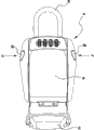
现在参考附图,图1是示例性实施例的保险箱10的前透视图。保险箱包括盖22,其绕壳体24的底部上的铰链旋转。盖22被示出处于部分打开位置,并且被设置成在不使用保险箱10时保护用户可操作的锁定界面。如图所示,用户可操作的锁定界面是多个密码拨盘。拨盘与设置在壳体内的锁定机构相互作用。壳体24限定用于存储例如钥匙的物品的内部隔间或腔(未示出)。Referring now to the drawings, FIG. 1 is a front perspective view of an exemplary embodiment safe 10 . The safe includes a
如所讨论的,在盖22处于打开位置的情况下,露出一组密码拨盘28、30、32、34。钩环26位于保险箱10的顶部。可以使用钩环26将保险箱10固定到各种地方,例如穿过壁挂式搭扣或者围绕门把手。保险箱10包括在壳体的任一侧面上的相对的侧面按钮36a、36b,当用户将密码拨盘组28、30、32、34转动到预定授权密码时,侧面按钮36a、36b可以被挤压。当沿图3所示的方向A1向内挤压侧面按钮36a、36b时,可以打开保险箱门35,以使用户可以进入内部隔间。As discussed, with the
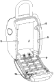
图2a是另一保险箱的前透视图。没有钩环的保险箱40可以是壁挂式的,并且被示出用盖22关闭。这样,密码拨盘不可见。稍后更详细地论述壁挂式保险箱40。图2b是另一保险箱42的前透视图。盖44位于一组密码拨盘(未示出)上。与其他示出的保险箱20、40的盖22相比,盖44的长度相对较短。关节式臂杆(未示出)将盖沿锁体转移到较低位置,使拨盘露出给用户操作。本领域普通技术人员应当明白,本发明可以在具有任意合适长度的盖的情况下,在没有任何盖的情况下以及在具有或者没有钩环的情况下实施。Figure 2a is a front perspective view of another safe. A safe 40 without a shackle may be wall mounted and is shown closed with a
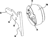
在图4a中示出保险箱10的后视图。盖22打开并且没有示出壳体24和门35,以表明保险箱10的其他特征。图4b是图4a的一部分的放大视图,包括侧面按钮组件38b(见图5a和5b)。在图4a的示例性实施例中,实质上镜像的侧面按钮组件36a位于保险箱10的相对的侧面。如从图4b最佳地看出的,侧面按钮36b与释放突片50接合。在图4a和4b所示的位置,闩锁60的外端58b阻挡门从关闭位置(见图3)移到打开位置(见图7)。外缘可以是锥形的。当由授权用户正确地操作密码拨盘组到预定密码时,用户可以接合按钮36a、36b,以打开门35并存取内部隔间的内容物。通过在侧面按钮36a、38b的平齐表面上推入,抵靠着闩锁60的外端58向内按下释放突片50的舌部52(如图6a所示)。A rear view of the safe 10 is shown in FIG. 4a.
本发明的锁的一个或两个侧面可以包括侧面按钮组件。如图所示,锁10包括侧面按钮组件38a、38b。无论如何,侧面按钮和释放突片的组件被布置成抵抗未授权用户的攻击或其他操作。侧面按钮与壳体的外表面平齐以限制撬开的效果。侧面按钮还包括脱离防拨弄装置。图5a是侧面按钮36a的后透视图,其被示出与释放突片50接合。两个凸起54的尺寸被设置成接合释放突片上的孔口56。也可以使用其他接合设计。如果未授权用户企图撬开或者以其他方式攻击侧面按钮36b,则被接合的释放突片50将脱离按钮。一旦突片50从按钮脱开,则用户越来越难以用舌部52驱动闩锁60,从而释放机构禁止打开保险箱。One or both sides of the lock of the present invention may include a side button assembly. As shown, the
如所讨论的,示例性保险箱具有两个机构,禁止未授权地存取保险箱的内容物。在用户能够正确地操作侧面按钮之前,必须正确地操作锁定机构。图6a是保险箱10的一部分的后视图,没有示出壳体、门或盖。示出了保险箱的后侧以及密码拨盘28、30、32、34。四个密码拨盘延伸通过壳体24中的槽,从而可被用户访问。虽然示例性拨盘28、30、32、34被示出建议标记为“0”至“9”的十个增量,但是拨盘可以设置有不同数量的增量以及不同的标记,例如字母、符号或颜色。此外,还可以使用不同数量的拨盘。As discussed, the exemplary safe has two mechanisms that prohibit unauthorized access to the contents of the safe. The locking mechanism must be properly operated before the user can properly operate the side buttons. Figure 6a is a rear view of a portion of the safe 10 without the housing, door or cover shown. The rear side of the safe and combination dials 28, 30, 32, 34 are shown. Four combination dials extend through slots in the
如图6a和6b所示,保险箱10的双重锁定结构包括第二锁定机构。第二机构可以起到释放机构的作用,以允许在已经正确地操作第一锁定机构之后打开门。如图所示,释放机构包括具有集成式弹簧62的相对的闩锁60。相对的闩锁限定两个对准的槽76。释放机构被设置和布置成与第一锁定机构的选择特征相互作用,包括具有锁定突片66的笼式阻挡器64,以及多个密码拨盘的四个拨盘毂68。每个毂限定平坦的表面。在门35处于关闭位置和锁定状态的情况下,突片66位于闩锁60之间并且在槽76的外侧,如图6a所示。在该位置,突片66禁止通过压下按钮36a、36b而向内移动。As shown in Figures 6a and 6b, the double locking structure of safe 10 includes a second locking mechanism. The second mechanism may function as a release mechanism to allow the door to be opened after the first locking mechanism has been properly operated. As shown, the release mechanism includes opposing latches 60 with
当四个拨盘28、30、32、34旋转到预定授权密码时,具有掣子(detent)70的拨盘毂68在排列中轴向地排成一行,以产生平坦的表面。一旦产生平坦的表面,则允许笼式阻挡器64的底部通过弹簧74的偏置向内移动。在该位置,笼式阻挡器的锁定突片66朝向保险箱10外侧移动并进入每个闩锁60所限定的槽76中。在笼式阻挡器64充分移动以允许闩锁60向内移动的情况下,可以沿方向A1向内挤压侧面按钮36a、36b,以驱动具有集成式弹簧62的闩锁60打开。这样,每个闩锁60的外缘58离开开口59的外缘,将门35从锁定状态移到解锁状态。在移去闩锁的情况下,可将门34从保险箱壳体24上移开,以便进入保险箱10的内部。例如,门可以被力弹开到图7的打开位置。如通过打开位置的门可见,第一和第二锁定机构安装在壳体内,位于门的内侧顶表面上。在壳体内侧壁上示出孔口92,在门处于关闭位置的情况下,闩锁外缘58b延伸通过孔口92。As the four dials 28, 30, 32, 34 are rotated to a predetermined authorized combination, the
如所讨论的,通过不在保险箱的外侧面上设置任何外部凸出或延伸部,加强了保险箱的附加安全性。为此,保险箱20包括由抗扭弹簧90偏置的门24,如图7和8a所示。保险箱包括集成式弹簧,其在按钮36a、36b被释放时允许门弹开。弹簧90可以用在任何实施例中,并且可以改变形状、位置和大小。As discussed, the additional security of the safe is enhanced by not providing any external protrusions or extensions on the outside of the safe. To this end, the safe 20 includes a
图8b是图8a的保险箱20的局部分解图。壁挂式保险箱20具有衬垫80,以强化安装螺栓界面。衬垫可以由钢或任何其他合适的材料制成。衬垫80放在存储腔内。然后,安装螺栓82穿过相应的衬垫中的孔84和壳体中的孔86固定到保险箱20的内侧。如果未授权用户将保险箱20撬离墙壁,则衬垫80依然固定住安装螺栓头。由于难以将螺栓头拉出穿过衬垫80中的孔84,所以该布置导致了强度更高的组件。Figure 8b is a partially exploded view of the safe 20 of Figure 8a. The wall safe 20 has
尽管在此描述以及说明了示例性实施例的组合中所体现的本发明的各创造性方面、构思以及特征,但是这些各种方面、构思以及特征可以单独地或者以其各种组合及子组合用在许多替换实施例中。除非在此明确地排除,所有这样的组合以及子组合都意图在本发明的范围内。另外,虽然在此描述了关于本发明各方面、构思以及特征的各种替换实施例,诸如替换材料、结构、构造、方法、电路、设备和部件、软件、硬件、控制逻辑、关于形式、配合及功能的替换、等等,但是这样的描述并不意图完全或彻底列出可得到的替换实施例,不管是目前已知的或是随后开发的。本领域技术人员可以将一个或多个创造性方面、构思或特征容易地应用到另一实施例中,并且在本发明的范围内使用,即使在此并没有特别公开这样的实施例。另外,即使在此将本发明的一些特征、构思或方面作为优选的装置或方法进行了描述,这样的描述也不意图建议如此特征是需要的或必需的,除非明确地如此指出。另外,为了帮助理解本公开的内容,可以包括示例性或代表性的值以及范围;然而,这样的值以及范围并不视为是限制性的,并且仅在明确指出时才意图为关键值或范围。此外,虽然在此各方面、特征以及构思可以特别识别为发明或成为本发明的一部分,但是如此识别并不意图是排它的,而宁可是有在此完全描述的创造性方面、构思以及特征,没有明确地识别为如此或作为具体发明的一部分。示例性方法或过程的描述并不局限于包括所有情况需要的所有步骤,步骤所呈现的顺序也不认为是需要的或必需,除非明确地如此指出。Although various inventive aspects, concepts and features of the invention have been described and illustrated herein as embodied in combinations of exemplary embodiments, these various aspects, concepts and features may be used alone or in various combinations and subcombinations thereof. In many alternative embodiments. Unless here clearly got rid of, all such combinations and sub-combinations are intended to be within the scope of the present invention. Additionally, although various alternative embodiments have been described herein with respect to aspects, concepts, and features of the invention, such as alternative materials, structures, configurations, methods, circuits, devices and components, software, hardware, control logic, in terms of form, coordination, and functional substitutions, etc., but such description is not intended to be a complete or exhaustive listing of available alternative embodiments, whether now known or subsequently developed. A person skilled in the art may readily adapt one or more inventive aspects, concepts or features to another embodiment and use it within the scope of the present invention even if such embodiment is not specifically disclosed herein. Additionally, even though some features, concepts or aspects of the inventions are described herein as being a preferred means or method, such description is not intended to suggest that such feature is required or required unless expressly so stated. Additionally, exemplary or representative values and ranges may be included to aid in the understanding of the present disclosure; however, such values and ranges are not to be considered limiting, and are intended to be critical values or ranges only when expressly indicated. scope. Furthermore, although aspects, features and concepts herein may be specifically identified as inventive or part of the present invention, such identification is not intended to be exclusive, but rather there are inventive aspects, concepts and features fully described herein, Not explicitly identified as such or as part of a specific invention. Descriptions of exemplary methods or processes are not limited to including all steps required in all cases, nor is the order in which the steps are presented considered required or necessary unless expressly so indicated.
Claims (20)
Applications Claiming Priority (3)
| Application Number | Priority Date | Filing Date | Title |
|---|---|---|---|
| US25725309P | 2009-11-02 | 2009-11-02 | |
| US61/257253 | 2009-11-02 | ||
| PCT/US2010/055039 WO2011053949A1 (en) | 2009-11-02 | 2010-11-02 | Safe with dual locking mechanism |
Publications (2)
| Publication Number | Publication Date |
|---|---|
| CN102667035A true CN102667035A (en) | 2012-09-12 |
| CN102667035B CN102667035B (en) | 2015-02-18 |
Family
ID=43922624
Family Applications (1)
| Application Number | Title | Priority Date | Filing Date |
|---|---|---|---|
| CN201080049123.4A Expired - Fee Related CN102667035B (en) | 2009-11-02 | 2010-11-02 | Safe with dual locking mechanism |
Country Status (9)
| Country | Link |
|---|---|
| US (1) | US8695385B2 (en) |
| EP (1) | EP2496780A4 (en) |
| JP (1) | JP2013509516A (en) |
| CN (1) | CN102667035B (en) |
| AU (1) | AU2010313163B2 (en) |
| CA (1) | CA2779078C (en) |
| MX (1) | MX2012005089A (en) |
| WO (1) | WO2011053949A1 (en) |
| ZA (1) | ZA201203138B (en) |
Cited By (2)
| Publication number | Priority date | Publication date | Assignee | Title |
|---|---|---|---|---|
| CN103485609A (en) * | 2013-04-12 | 2014-01-01 | 陈宏伟 | Dual-channel luggage coded lock |
| CN107069262A (en) * | 2013-06-26 | 2017-08-18 | 阿维科斯公司 | Electric connector |
Families Citing this family (28)
| Publication number | Priority date | Publication date | Assignee | Title |
|---|---|---|---|---|
| TWI381090B (en) * | 2009-09-09 | 2013-01-01 | Shopin Lock Co Ltd | Padlock having a storage chamber |
| US20110226023A1 (en) * | 2009-12-23 | 2011-09-22 | Tim Freeman | Key storage lock box |
| TW201211371A (en) * | 2010-08-23 | 2012-03-16 | Shyh Ru Metallic Ind Corp | Electronic cash box |
| US8141396B1 (en) * | 2010-09-10 | 2012-03-27 | Yao Kun Yang | Lock box assembly |
| USD658876S1 (en) | 2011-06-20 | 2012-05-08 | Timothy Holobinko | Locker |
| US20130234478A1 (en) * | 2012-03-06 | 2013-09-12 | Robert Michael Peck | Portable, Universally fitting, lockable container that attaches to fixed objects to store valuables |
| CN102730303B (en) * | 2012-07-12 | 2014-08-13 | 上虞中瑞塑胶有限公司 | Disposable package box with coded lock |
| US8966946B2 (en) * | 2013-05-28 | 2015-03-03 | The Sun Lock Company, Ltd. | Combination key lock box with anti-pick mechanism |
| US9423211B2 (en) * | 2014-11-03 | 2016-08-23 | Truckvault, Inc. | Locking container for firearms |
| DE102015003171A1 (en) * | 2015-03-13 | 2016-09-15 | Sudhaus Gmbh & Co. Kg | Key safe for attachment to a mounting surface |
| US9540845B1 (en) * | 2015-07-14 | 2017-01-10 | Yao-Kun Yang | Lock unit with a room therein |
| US9663971B2 (en) * | 2015-09-20 | 2017-05-30 | Yao-Kun Yang | Combination lock |
| EP3414413B1 (en) * | 2016-02-12 | 2020-01-08 | Master Lock Company LLC | Lockable enclosure with combination locking mechanism |
| US10184268B2 (en) | 2016-02-23 | 2019-01-22 | Fath, Inc. | Security swing handle assembly |
| US10648196B2 (en) | 2018-01-31 | 2020-05-12 | Master Lock Company Llc | Lockbox with multi-position shackle |
| USD895397S1 (en) | 2018-06-12 | 2020-09-08 | Frank J. Martin Company | Storage locker pad lock |
| US10890015B2 (en) | 2018-09-21 | 2021-01-12 | Knox Associates, Inc. | Electronic lock state detection systems and methods |
| CN111402457A (en) * | 2019-01-03 | 2020-07-10 | 上海助邦信息技术有限公司 | Portable storage box |
| USD876044S1 (en) * | 2019-06-21 | 2020-02-18 | Urban Safes, Llc | Safe |
| US11017625B2 (en) * | 2019-06-26 | 2021-05-25 | Lubn Inc. | Smart key box |
| CN112983141A (en) * | 2019-12-02 | 2021-06-18 | 炬众钛合(天津)科技发展有限公司 | Electronic safety lock and packing material |
| US11674349B2 (en) * | 2020-06-09 | 2023-06-13 | Ncr Corporation | Slim profile safe |
| USD1065978S1 (en) | 2021-10-14 | 2025-03-11 | Master Lock Company Llc | Lock box |
| US20230358076A1 (en) * | 2022-05-05 | 2023-11-09 | Shenzhen Hanmai Technology Co., Ltd | Key case |
| US12589651B1 (en) * | 2023-07-06 | 2026-03-31 | Kyle Heaser | Sobriety check locking key case |
| JP7765108B2 (en) * | 2024-03-06 | 2025-11-06 | 株式会社Stコーポレーション | Key Box |
| USD1102871S1 (en) | 2024-10-21 | 2025-11-25 | Neo Apex Limited | Key storage lock box |
| JP7732697B1 (en) * | 2025-01-22 | 2025-09-02 | 株式会社Stコーポレーション | Key Box |
Citations (7)
| Publication number | Priority date | Publication date | Assignee | Title |
|---|---|---|---|---|
| US4838052A (en) * | 1987-07-23 | 1989-06-13 | Segwill Corp. | Lock system |
| US4872326A (en) * | 1987-12-10 | 1989-10-10 | Aurness Harold O | Three stage combination replacement lock |
| US6318134B1 (en) * | 1998-07-14 | 2001-11-20 | Mossberg Safe Systems, Inc. | Safe locking mechanism |
| US20040226325A1 (en) * | 2003-05-12 | 2004-11-18 | Ling Renny Tse-Haw | Securing box |
| TWM290522U (en) * | 2005-03-22 | 2006-05-11 | Shopin Lock Co | Padlock having receiving space |
| TWM341083U (en) * | 2008-04-08 | 2008-09-21 | Sinox Co Ltd | Keypad-type anti-burglary device |
| CN101529036A (en) * | 2006-10-31 | 2009-09-09 | 总锁有限责任公司 | Mounting type safety device |
Family Cites Families (99)
| Publication number | Priority date | Publication date | Assignee | Title |
|---|---|---|---|---|
| US229995A (en) * | 1880-07-13 | freeman | ||
| US145835A (en) * | 1873-12-23 | Improvement in berth-locks for sleeping-cars | ||
| US290729A (en) * | 1883-12-25 | Box-fastener | ||
| US195117A (en) * | 1877-09-11 | Improvement in trunk-fastenings | ||
| US311134A (en) * | 1885-01-20 | Half to john phipps | ||
| US120419A (en) * | 1871-10-31 | Improvement in fasteners for meeting-rails of sashes | ||
| US946570A (en) * | 1909-04-24 | 1910-01-18 | David A Teeter | Sash-lock. |
| US1133254A (en) * | 1912-07-26 | 1915-03-30 | Henry N Backus | Crate-lock. |
| US1185422A (en) * | 1916-01-17 | 1916-05-30 | Dominick P Mammelli | Window-latch. |
| US1634884A (en) * | 1926-05-19 | 1927-07-05 | Edward S Peer | Safety deposit receptacle |
| US1955809A (en) * | 1933-07-13 | 1934-04-24 | Hobbs Ralph | Safety box |
| US2108965A (en) * | 1934-02-19 | 1938-02-22 | Gen Motors Corp | Latch |
| US2625293A (en) * | 1949-02-17 | 1953-01-13 | Lake State Products | Hinged lid actuator and prop |
| US2755748A (en) * | 1953-05-04 | 1956-07-24 | Jr Parker E Abell | Portable lock box |
| US3026704A (en) * | 1959-08-14 | 1962-03-27 | American Hardware Corp | Lock mounting means |
| US3084532A (en) * | 1960-09-30 | 1963-04-09 | Delbert A Williams | Portable key safe |
| US3146739A (en) * | 1962-07-27 | 1964-09-01 | Furman Murray | Combination of strongbox and anchoring means |
| US3742741A (en) * | 1972-04-03 | 1973-07-03 | L Cahan | Key receptacle for an automotive vehicle |
| US3788007A (en) * | 1972-04-26 | 1974-01-29 | Pullman Inc | Freight car door latching device |
| US3934434A (en) * | 1973-09-24 | 1976-01-27 | Jack Law | Key safe apparatus |
| US4109950A (en) * | 1977-01-31 | 1978-08-29 | Keystone Consolidated Industries, Inc. | Door opener and latch |
| US4252363A (en) * | 1979-04-12 | 1981-02-24 | Wilbrod Rodrigue | Foldaway canopy for flatbed truck |
| USD273053S (en) * | 1981-11-02 | 1984-03-13 | Hamborg Peter M | Elastomeric magnetized key container |
| USD271350S (en) * | 1981-12-21 | 1983-11-15 | Robbins Thomas R | Combined key holder and coin purse |
| USD278689S (en) * | 1982-05-27 | 1985-05-07 | Jupe Carlen R | Parking meter |
| US4641505A (en) * | 1982-12-27 | 1987-02-10 | Maurice Thomas A | Security device for real estate brokers |
| USD279324S (en) * | 1983-01-17 | 1985-06-18 | Tanaka Manufacturing Co., Ltd. | Coin tray for vehicles |
| JPS6147742U (en) * | 1984-09-03 | 1986-03-31 | 日本発条株式会社 | Trunk-through-seat trunk lid locking device |
| US4651544A (en) * | 1984-10-16 | 1987-03-24 | Hungerford Robert E | Exterior entry door tethered key safe |
| USD298679S (en) * | 1985-05-24 | 1988-11-22 | Viro Innocenti S.P.A. | Wall safe |
| US4914732A (en) * | 1985-10-16 | 1990-04-03 | Supra Products, Inc. | Electronic key with interactive graphic user interface |
| USD309054S (en) * | 1987-08-12 | 1990-07-03 | Mag-Nif, Inc. | Savings bank |
| USD310211S (en) * | 1987-09-14 | 1990-08-28 | Kabushiki Kaisha Toshiba | Access security control terminal |
| US4951577A (en) * | 1989-01-11 | 1990-08-28 | Bentley James K | Wall safe assembly |
| US5065156A (en) * | 1990-07-26 | 1991-11-12 | Denis Bernier | Computer controlled parking meter |
| JPH0571255A (en) * | 1991-09-12 | 1993-03-23 | Hajime Yamazaki | Key-holder device |
| WO1994012749A1 (en) * | 1992-12-01 | 1994-06-09 | Access Technology, Inc. | Key safe for housing a key |
| USD351499S (en) * | 1993-04-19 | 1994-10-18 | Jean-Philippe Gay | Case for a multimedia marketing system |
| USD350002S (en) * | 1993-10-12 | 1994-08-23 | Viola Christopher J | Lockable delivery box for entertainment articles |
| USD365430S (en) * | 1994-05-25 | 1995-12-19 | Riboli Charles T | Savings bank |
| US5758522A (en) * | 1996-11-12 | 1998-06-02 | Microsoft Corporation | Access control system for security enclosure |
| USD380793S (en) * | 1995-07-27 | 1997-07-08 | Confectionery and Novelty Design Intl. | Toy safe |
| US5738020A (en) * | 1995-09-12 | 1998-04-14 | Correia; Lewis A. | Lock box and mounting device |
| TW341083U (en) * | 1995-10-28 | 1998-09-21 | Fang-Hui Huang | A cradle rail safety pin |
| JPH09121931A (en) * | 1995-11-01 | 1997-05-13 | Yoshida Kogyo Kk <Ykk> | Cosmetic container |
| US5737947A (en) * | 1997-05-02 | 1998-04-14 | Ling; Chong-Kuan | Mother-and-daughter combination lock |
| US5927114A (en) * | 1997-05-19 | 1999-07-27 | Berry; Daniel | View limiting enclosure assembly for dial combination locks |
| USD407184S (en) * | 1997-09-10 | 1999-03-23 | Richard Warren Endelson | Money holder |
| US6082155A (en) * | 1998-10-02 | 2000-07-04 | Su; Shun-Chang | Pad locks with changeable code number |
| USD432755S (en) * | 1999-02-10 | 2000-10-24 | Jerzy Perkitny | Bank for paper money |
| JP2000275715A (en) * | 1999-03-26 | 2000-10-06 | Ricoh Co Ltd | Electronic camera |
| US6732664B2 (en) * | 2000-08-07 | 2004-05-11 | Charles H. Worrall | Key and combination locking mechanism |
| US6381997B1 (en) * | 2001-04-20 | 2002-05-07 | Chen Cheng Jung | Combination padlock |
| US20030141959A1 (en) * | 2001-06-29 | 2003-07-31 | Keogh Colin Robert | Fingerprint biometric lock |
| USD462517S1 (en) * | 2001-11-07 | 2002-09-10 | Mag-Nif Incorporated | Key holder |
| USD484776S1 (en) * | 2002-11-21 | 2004-01-06 | Wah Yuet (Ng's) Co., Ltd. | Padlock |
| US7424812B2 (en) | 2003-05-16 | 2008-09-16 | Stanton Concepts Inc. | Multiple function lock |
| US7434426B2 (en) * | 2003-05-16 | 2008-10-14 | Stanton Concepts Inc. | Multiple function lock |
| DE10323641A1 (en) * | 2003-05-26 | 2005-01-05 | Daimlerchrysler Ag | Movable sensor device on the load means of a forklift |
| US6792778B1 (en) * | 2003-09-09 | 2004-09-21 | Glox Industry Co., Ltd. | Combination lock |
| US6813912B1 (en) * | 2004-01-14 | 2004-11-09 | Loyal International Inc. | Secure lockbox |
| US6834519B1 (en) * | 2004-01-15 | 2004-12-28 | Yao-Kun Yang | Padlock having receiving chamber inside |
| TWM265430U (en) * | 2004-04-09 | 2005-05-21 | Fullyear Brother Entpr Co Ltd | Storage apparatus for safety check media of lock |
| TWM267899U (en) * | 2004-04-14 | 2005-06-21 | Fullyear Brother Entpr Co Ltd | Depositing apparatus of suitcase security checking medium |
| US20060065024A1 (en) * | 2004-09-28 | 2006-03-30 | Gutierrez Glennda T | Decorative lock cover |
| USD539540S1 (en) * | 2004-10-08 | 2007-04-03 | Blue Chip Group, Llc | Storage device |
| US7416065B2 (en) * | 2004-12-27 | 2008-08-26 | Levinson Lawrence S | Shoe case |
| JP4412234B2 (en) * | 2005-05-24 | 2010-02-10 | 豊田合成株式会社 | Glove box |
| USD534965S1 (en) * | 2005-08-03 | 2007-01-09 | Action Electronics Co., Ltd. | Safebox toy |
| TWI275693B (en) * | 2006-01-05 | 2007-03-11 | Sinox Co Ltd | Burglarproof lock for an electrical device |
| TWI292006B (en) * | 2006-01-05 | 2008-01-01 | Sinox Co Ltd | Lock box |
| US7152439B1 (en) * | 2006-02-01 | 2006-12-26 | Vulcan Sports Co., Ltd. | Padlock |
| US7131299B1 (en) * | 2006-05-16 | 2006-11-07 | Glox Industry Co., Ltd. | Combination lock and padlock combination with opening warning device |
| USD549552S1 (en) * | 2006-05-16 | 2007-08-28 | Glox Industry Co., Ltd. | Combination lock and padlock combination with opening alert device |
| US7299667B1 (en) * | 2006-06-02 | 2007-11-27 | Miresmaili Masoud S | Vault assembly |
| US7765840B2 (en) * | 2006-10-04 | 2010-08-03 | The Sun Lock Company Ltd. | Dual locking padlock |
| US7426841B2 (en) * | 2006-11-17 | 2008-09-23 | Yao-Kun Yang | Lock having slidable box |
| US7516631B2 (en) * | 2006-12-01 | 2009-04-14 | Master Lock Company Llc | Safe with locking cartridge door |
| EP2121469A4 (en) | 2007-01-26 | 2013-12-04 | Master Lock Co | Tethered portable storage device |
| USD569609S1 (en) * | 2007-01-26 | 2008-05-27 | Master Lock Company Llc | Safe |
| TWM322981U (en) * | 2007-03-13 | 2007-12-01 | Shopin Lock Co | Complex padlock |
| USD560875S1 (en) * | 2007-04-11 | 2008-01-29 | Ideastream Consumer Products, Llc | Closet storage device |
| US20090095036A1 (en) * | 2007-10-16 | 2009-04-16 | Kwan Yuen Ng | Lockbox with user configured combination locks |
| US7946141B2 (en) | 2008-04-29 | 2011-05-24 | Kwan Yuen Abraham Ng | Self-scrambling combination lock |
| CA129287S (en) * | 2008-07-16 | 2009-10-14 | Comptoir Nouveau De La Parfumerie | BOTTLE |
| USD590695S1 (en) * | 2008-10-21 | 2009-04-21 | Kun-Yu Wu | Padlock |
| USD592934S1 (en) * | 2008-12-09 | 2009-05-26 | Yao-Kun Yang | Padlock |
| US20100242553A1 (en) * | 2009-03-31 | 2010-09-30 | Yao-Kun Yang | Locking device for protecting door lock |
| USD641535S1 (en) * | 2009-04-02 | 2011-07-12 | Benison Industrial Co. Ltd. | Apple shaped coin bank |
| US8020415B2 (en) * | 2009-06-04 | 2011-09-20 | Stampp W. Corbin | Locking pill bottle |
| JP5153749B2 (en) * | 2009-10-07 | 2013-02-27 | ケイデン・セキュリティー機器販売株式会社 | Key box structure |
| USD630260S1 (en) | 2009-10-22 | 2011-01-04 | Trent Cole | Childs toy lock |
| USD623824S1 (en) | 2009-12-21 | 2010-09-14 | Pendleton Safe Company | Safe |
| TWM397365U (en) * | 2010-02-26 | 2011-02-01 | qiu-song Wang | Container |
| USD634915S1 (en) * | 2010-03-29 | 2011-03-22 | Master Lock Company Llc | Safe |
| USD635324S1 (en) | 2010-06-02 | 2011-03-29 | Master Lock Company Llc | Safe |
| USD635325S1 (en) | 2010-06-02 | 2011-03-29 | Master Lock Company Llc | Safe |
| USD638684S1 (en) | 2010-07-27 | 2011-05-31 | Master Lock Company Llc | Lock |
| USD642893S1 (en) | 2010-12-28 | 2011-08-09 | Yao Kun Yang | Combination lock |
-
2010
- 2010-11-02 MX MX2012005089A patent/MX2012005089A/en active IP Right Grant
- 2010-11-02 WO PCT/US2010/055039 patent/WO2011053949A1/en not_active Ceased
- 2010-11-02 CA CA 2779078 patent/CA2779078C/en not_active Expired - Fee Related
- 2010-11-02 US US12/917,613 patent/US8695385B2/en active Active
- 2010-11-02 AU AU2010313163A patent/AU2010313163B2/en not_active Ceased
- 2010-11-02 CN CN201080049123.4A patent/CN102667035B/en not_active Expired - Fee Related
- 2010-11-02 EP EP20100827632 patent/EP2496780A4/en not_active Withdrawn
- 2010-11-02 JP JP2012537184A patent/JP2013509516A/en not_active Ceased
-
2012
- 2012-04-30 ZA ZA2012/03138A patent/ZA201203138B/en unknown
Patent Citations (7)
| Publication number | Priority date | Publication date | Assignee | Title |
|---|---|---|---|---|
| US4838052A (en) * | 1987-07-23 | 1989-06-13 | Segwill Corp. | Lock system |
| US4872326A (en) * | 1987-12-10 | 1989-10-10 | Aurness Harold O | Three stage combination replacement lock |
| US6318134B1 (en) * | 1998-07-14 | 2001-11-20 | Mossberg Safe Systems, Inc. | Safe locking mechanism |
| US20040226325A1 (en) * | 2003-05-12 | 2004-11-18 | Ling Renny Tse-Haw | Securing box |
| TWM290522U (en) * | 2005-03-22 | 2006-05-11 | Shopin Lock Co | Padlock having receiving space |
| CN101529036A (en) * | 2006-10-31 | 2009-09-09 | 总锁有限责任公司 | Mounting type safety device |
| TWM341083U (en) * | 2008-04-08 | 2008-09-21 | Sinox Co Ltd | Keypad-type anti-burglary device |
Cited By (3)
| Publication number | Priority date | Publication date | Assignee | Title |
|---|---|---|---|---|
| CN103485609A (en) * | 2013-04-12 | 2014-01-01 | 陈宏伟 | Dual-channel luggage coded lock |
| CN107069262A (en) * | 2013-06-26 | 2017-08-18 | 阿维科斯公司 | Electric connector |
| CN107069262B (en) * | 2013-06-26 | 2020-01-03 | 阿维科斯公司 | Electrical connector |
Also Published As
| Publication number | Publication date |
|---|---|
| WO2011053949A1 (en) | 2011-05-05 |
| EP2496780A4 (en) | 2015-02-25 |
| US8695385B2 (en) | 2014-04-15 |
| AU2010313163A1 (en) | 2012-06-07 |
| JP2013509516A (en) | 2013-03-14 |
| AU2010313163B2 (en) | 2014-08-21 |
| ZA201203138B (en) | 2013-01-30 |
| US20110100074A1 (en) | 2011-05-05 |
| CN102667035B (en) | 2015-02-18 |
| CA2779078C (en) | 2015-04-07 |
| MX2012005089A (en) | 2012-06-12 |
| CA2779078A1 (en) | 2011-05-05 |
| EP2496780A1 (en) | 2012-09-12 |
Similar Documents
| Publication | Publication Date | Title |
|---|---|---|
| CN102667035B (en) | Safe with dual locking mechanism | |
| CN102971469B (en) | lock mechanism | |
| CN102762806B (en) | Lockable enclosure | |
| US6564596B2 (en) | Door lock assembly with multiple latch devices | |
| US8234891B2 (en) | Combination cam lock with improved combination change mode | |
| CN102834575B (en) | Machinery pushing button locking is arranged | |
| US20170234038A1 (en) | Lockable enclosure with combination locking mechanism | |
| US9328534B2 (en) | Safe and lock mechanism | |
| US20180371792A1 (en) | Door lock mortise | |
| US9359789B2 (en) | Security assembly for use with a security console | |
| US20250237088A1 (en) | Locking enclosure | |
| US6886378B1 (en) | Container locking system | |
| JPH0849453A (en) | Lock-equipped door-knob cover | |
| KR200453700Y1 (en) | Locking device with display function | |
| JP7343165B2 (en) | Auxiliary lock | |
| KR102580801B1 (en) | Digital Doorlock | |
| US20130213099A1 (en) | Double-Lock Deadbolt | |
| KR20230167005A (en) | Side door latch device for fire engine | |
| KR20150079185A (en) | A locking structure for door | |
| EP2304140A1 (en) | Lock of slam- latch type |
Legal Events
| Date | Code | Title | Description |
|---|---|---|---|
| C06 | Publication | ||
| PB01 | Publication | ||
| C10 | Entry into substantive examination | ||
| SE01 | Entry into force of request for substantive examination | ||
| C14 | Grant of patent or utility model | ||
| GR01 | Patent grant | ||
| CF01 | Termination of patent right due to non-payment of annual fee |
Granted publication date: 20150218 Termination date: 20161102 |
|
| CF01 | Termination of patent right due to non-payment of annual fee |