CN102656669A - UV lamp assembly of degassing chamber having rotary shutters - Google Patents
UV lamp assembly of degassing chamber having rotary shutters Download PDFInfo
- Publication number
- CN102656669A CN102656669A CN2010800574542A CN201080057454A CN102656669A CN 102656669 A CN102656669 A CN 102656669A CN 2010800574542 A CN2010800574542 A CN 2010800574542A CN 201080057454 A CN201080057454 A CN 201080057454A CN 102656669 A CN102656669 A CN 102656669A
- Authority
- CN
- China
- Prior art keywords
- lamp
- rotary shutter
- lamp assembly
- degassing chamber
- light
- Prior art date
- Legal status (The legal status is an assumption and is not a legal conclusion. Google has not performed a legal analysis and makes no representation as to the accuracy of the status listed.)
- Granted
Links
Images


Classifications
-
- H—ELECTRICITY
- H10—SEMICONDUCTOR DEVICES; ELECTRIC SOLID-STATE DEVICES NOT OTHERWISE PROVIDED FOR
- H10P—GENERIC PROCESSES OR APPARATUS FOR THE MANUFACTURE OR TREATMENT OF DEVICES COVERED BY CLASS H10
- H10P70/00—Cleaning of wafers, substrates or parts of devices
- H10P70/10—Cleaning before device manufacture, i.e. Begin-Of-Line process
- H10P70/12—Cleaning before device manufacture, i.e. Begin-Of-Line process by dry cleaning only
-
- H—ELECTRICITY
- H10—SEMICONDUCTOR DEVICES; ELECTRIC SOLID-STATE DEVICES NOT OTHERWISE PROVIDED FOR
- H10P—GENERIC PROCESSES OR APPARATUS FOR THE MANUFACTURE OR TREATMENT OF DEVICES COVERED BY CLASS H10
- H10P72/00—Handling or holding of wafers, substrates or devices during manufacture or treatment thereof
- H10P72/04—Apparatus for manufacture or treatment
- H10P72/0431—Apparatus for thermal treatment
- H10P72/0436—Apparatus for thermal treatment mainly by radiation
-
- H—ELECTRICITY
- H10—SEMICONDUCTOR DEVICES; ELECTRIC SOLID-STATE DEVICES NOT OTHERWISE PROVIDED FOR
- H10P—GENERIC PROCESSES OR APPARATUS FOR THE MANUFACTURE OR TREATMENT OF DEVICES COVERED BY CLASS H10
- H10P70/00—Cleaning of wafers, substrates or parts of devices
-
- H—ELECTRICITY
- H10—SEMICONDUCTOR DEVICES; ELECTRIC SOLID-STATE DEVICES NOT OTHERWISE PROVIDED FOR
- H10P—GENERIC PROCESSES OR APPARATUS FOR THE MANUFACTURE OR TREATMENT OF DEVICES COVERED BY CLASS H10
- H10P70/00—Cleaning of wafers, substrates or parts of devices
- H10P70/20—Cleaning during device manufacture
-
- H—ELECTRICITY
- H10—SEMICONDUCTOR DEVICES; ELECTRIC SOLID-STATE DEVICES NOT OTHERWISE PROVIDED FOR
- H10P—GENERIC PROCESSES OR APPARATUS FOR THE MANUFACTURE OR TREATMENT OF DEVICES COVERED BY CLASS H10
- H10P72/00—Handling or holding of wafers, substrates or devices during manufacture or treatment thereof
- H10P72/04—Apparatus for manufacture or treatment
- H10P72/0402—Apparatus for fluid treatment
- H10P72/0406—Apparatus for fluid treatment for cleaning followed by drying, rinsing, stripping, blasting or the like
- H10P72/0408—Apparatus for fluid treatment for cleaning followed by drying, rinsing, stripping, blasting or the like for drying
Landscapes
- Physical Or Chemical Processes And Apparatus (AREA)
- Cleaning Or Drying Semiconductors (AREA)
- Drying Of Semiconductors (AREA)
- Apparatus For Disinfection Or Sterilisation (AREA)
- Physical Water Treatments (AREA)
- Container, Conveyance, Adherence, Positioning, Of Wafer (AREA)
Abstract
具有旋转式遮光器的UV灯总成,每个旋转式遮光器具有有反射凹面的凹壁。旋转式遮光器可在打开位置和关闭位置之间共同地旋转。在打开位置,旋转式遮光器不阻挡UV灯的UV光线离开UV灯总成,而在关闭位置,旋转式遮光器阻挡UV光线离开UV灯总成。

A UV lamp assembly with rotating shaders, each shader having a concave wall with a reflective surface. The rotating shaders can rotate together between an open position and a closed position. In the open position, the rotating shaders do not obstruct the UV light from leaving the UV lamp assembly, while in the closed position, the rotating shaders obstruct the UV light from leaving the UV lamp assembly.
Description
背景技术 Background technique
在半导体衬底的等离子体处理过程中,其中半导体衬底被暴露于含卤素的工艺气体中,所述工艺气体的残余物会残留在半导体衬底的表面上。这样的残余物会导致下游处理阶段中的半导体衬底中的瑕疵,且会污染处理管道中的其他半导体衬底。因此,期望从脱气腔室中的半导体衬底移除这样的残余物。During plasma processing of semiconductor substrates, in which the semiconductor substrate is exposed to a halogen-containing process gas, residues of the process gas may remain on the surface of the semiconductor substrate. Such residues can cause defects in semiconductor substrates in downstream processing stages and can contaminate other semiconductor substrates in the processing pipeline. Therefore, it is desirable to remove such residues from the semiconductor substrate in the degassing chamber.
发明内容 Contents of the invention
包括多个平行UV灯和旋转式遮光器的脱气腔室的UV灯总成,每个旋转式遮光器包括包围UV灯的凹壁和自所述凹壁的纵向边缘向外延伸的两个法兰,所述旋转式遮光器被配置为在打开位置和关闭位置之间旋转,其中处于打开位置的所述旋转式遮光器被布置于所述UV灯上方以便不阻挡所述UV灯的UV光线进入所述脱气腔室;且处于关闭位置的所述旋转式遮光器被布置于所述UV灯下方以便阻挡所述UV灯的UV光线进入所述脱气腔室,在所述关闭位置,相邻旋转式遮光器的所述法兰重叠以防止UV光线泄漏。A UV lamp assembly for a degassing chamber comprising a plurality of parallel UV lamps and rotating shutters each comprising a recessed wall surrounding the UV lamps and two flange, the rotary shutter is configured to rotate between an open position and a closed position, wherein the rotary shutter in the open position is arranged above the UV lamp so as not to block the UV of the UV lamp light enters the degassing chamber; and the rotary shutter in the closed position is arranged below the UV lamp so as to block the UV light of the UV lamp from entering the degassing chamber, in the closed position , said flanges of adjacent rotary shutters overlap to prevent UV light leakage.
附图说明 Description of drawings
图1示出了包括UV灯总成的脱气腔室的示意性横截面。Figure 1 shows a schematic cross-section of a degassing chamber including a UV lamp assembly.
图2a示出了旋转式遮光器的透视图。Figure 2a shows a perspective view of a rotary shutter.
图2b示出了图2a中的旋转式遮光器的端部的放大顶视图。Figure 2b shows an enlarged top view of the end of the rotary shutter in Figure 2a.
图3示出了图1的UV灯总成的示意性横截面,其中旋转式遮光器处于打开位置。Figure 3 shows a schematic cross-section of the UV lamp assembly of Figure 1 with the rotary shutter in an open position.
图4示出了图1的UV灯总成的示意性横截面,其中旋转式遮光器处于关闭位置。Figure 4 shows a schematic cross-section of the UV lamp assembly of Figure 1 with the rotary shutter in the closed position.
图5a示出了UV灯总成的透视图,其中旋转式遮光器处于打开位置。Figure 5a shows a perspective view of the UV lamp assembly with the rotary shutter in the open position.
图5b示出了UV灯总成的透视图,其中旋转式遮光器处于关闭位置。Figure 5b shows a perspective view of the UV lamp assembly with the rotary shutter in the closed position.
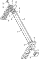
图6示出了根据一实施方式的UV灯总成的局部分解图。Fig. 6 shows a partially exploded view of a UV lamp assembly according to an embodiment.
图7示出了根据另一实施方式的UV灯总成的局部分解图。Fig. 7 shows a partially exploded view of a UV lamp assembly according to another embodiment.
图8示出了图7的UV灯总成的透视图,其中旋转式遮光器处于关闭位置。Figure 8 shows a perspective view of the UV lamp assembly of Figure 7 with the rotary shutter in a closed position.
图9示出了图7的UV灯总成的透视图,其中旋转式遮光器处于打开位置。Figure 9 shows a perspective view of the UV lamp assembly of Figure 7 with the rotary shutter in an open position.
具体实施方式 Detailed ways
图1示出了示例性脱气腔室100的示意性横截面。脱气腔室100包括由诸如铝等金属材料制成的室壁10。石英窗30被多个夹具40固定于室壁10的顶部。石英窗30优选地由合成石英制成,由于合成石英的UV光线高透射率。合成石英通常在热压罐中经热液工艺被解开(untwine)和生产。石英窗30和室壁10之间的连续O型环35提供真空密封。UV灯总成80被设置在石英窗30上方,中间优选地有间隙。真空泵60与脱气腔室100通过排气口相连接,所述排气口可被阀65关闭。气体源70与脱气腔室100通过输气管道相连接,所述输气管道可被另一阀75关闭。FIG. 1 shows a schematic cross-section of an
石英窗30被配置为安装在脱气腔室100的顶部上,其中,来自UV灯总成80的UV光线被传播通过石英窗30,同时,诸如臭氧或氧气之类的气体流入脱气腔室100,以从被支撑于脱气腔室100中的诸如300mm晶片等半导体衬底50上移除诸如蚀刻副产品之类的含卤素的残余物。石英窗30的细节在共同转让的美国专利申请12/607,659中被公开,在此将其作为参考引入。但是,UV灯总成80能以不同于图1中所示的方式和脱气腔室系统一起被使用。The
参考图1,在脱气腔室100中的处理过程中,半导体衬底50通过室壁10中的加载门20被移动并被放置于多个衬底支撑销(support pin)55上。脱气腔室100被真空泵60排空且来自气体源70的臭氧或氧气流入脱气腔室100。脱气腔室100中的气压优选地维持在10mTorr到10Torr。UV灯总成80用UV光线(优选波长254nm且强度在0.05到5W/cm2之间的)穿过石英窗30照射半导体衬底50达10钞到1分钟的时间。臭氧或氧气吸收UV光线并分解为O自由基(原子氧),O自由基与半导体衬底50上的含卤素的残余物起反应。反应产物是气态的并被真空泵60排出脱气腔室100。Referring to FIG. 1 , during processing in a
在输送半导体衬底50进出脱气腔室100的过程中,期望防止UV灯总成80的UV光线逸出脱气腔室100,以保护附近的人类操作员以及设备。但是,为了使处理衬底时的延迟减到最少以及为了防止UV灯85的过早损坏,期望UV灯总成80中的UV灯85保持上电状态而不是在每个衬底输送过程中被开和关。During transport of the
UV灯总成80包括旋转式遮光器90,旋转式遮光器90可被旋转到关闭位置以在脱气腔室100中不需要UV灯时(比如在输送衬底50进出脱气腔室100的过程中)阻挡来自UV灯85的UV光线。当来自UV灯85的UV光线被脱气工艺需要时,UV灯总成80中的旋转式遮光器90可被旋转到打开位置并允许UV光线到达脱气腔室100中的衬底50。The
图2a示出了根据一实施方式的旋转式遮光器90的透视图。旋转式遮光器90包括凹(例如,半圆柱形、半棱柱形)壁95和沿着凹壁95的纵向边缘向外延伸的两个优选共面的法兰93和94。法兰93和94优选地具有大约0.07到0.09英寸的宽度。旋转式遮光器90由不透UV光线的材料制成,比如铝。凹壁95的凹面91优选地是反射面(比如抛光的裸露铝表面)。脱气腔室100暴露于UV灯总成80的UV光线的内表面优选地被制成
优选地,法兰93和94不到凹壁95的末端以在纵向上提供离凹壁95的每个末端边缘至少大约0.1英寸的间隙,这允许凹壁95被接收在支撑构件的沟槽中。图2b示出了旋转式遮光器90的端部的放大顶视图。Preferably, the
图3示出了根据一实施方式的UV灯总成80的横截面示意图,其中旋转式遮光器90处于打开位置。UV灯总成80包括设置为彼此平行的多个UV灯85。UV灯85可被布置为互相平行且优选地覆盖石英窗30的大体上整个区域以实现该腔室中的衬底上方的均匀的UV光线强度。UV灯85可具有与覆盖石英窗30相比所需长度相同或不同的长度。一个旋转式遮光器90包围一个UV灯85。每个UV灯85可具有管状、双管状或其他合适的形状。在打开位置,旋转式遮光器90被布置在UV灯85上方而来自UV灯85的UV光线可直接穿过石英窗30进入脱气腔室100。每个旋转式遮光器90的凹面91向下反射UV光线以增加UV光线的强度和均匀度。旋转式遮光器90在脱气工艺过程中被维持在打开位置。FIG. 3 shows a schematic cross-sectional view of a
图4示出了根据一实施方式的UV灯总成80的横截面示意图,其中旋转式遮光器90处于关闭位置。在关闭位置,旋转式遮光器90被布置在UV灯85下方并阻挡来自UV灯85的UV光线的很大一部分(优选地大于99%)穿过所述窗30。在关闭位置,一个旋转式遮光器90的法兰93的下侧面与相邻旋转式遮光器的法兰94的上侧面重叠优选大约0.03到0.05英寸,更优选地大约0.04英寸以使UV光线的泄漏减到最少。FIG. 4 shows a schematic cross-sectional view of a
通过围绕UV灯85同时旋转所有的旋转式遮光器90大约180°,可将旋转式遮光器90从打开位置旋转到关闭位置。通过按相反方向同时旋转所有的旋转式遮光器90大约180°,可将旋转式遮光器90从关闭位置旋转到打开位置。The
旋转式遮光器90可在打开位置和关闭位置之间被任何合适的装置驱动。当旋转式遮光器90从关闭位置移动到打开位置时,UV灯85优选地保持固定且不旋转。对于双管状UV灯85来说,最外面的UV灯85a可以是有角度的以便将双管中的一者置为较靠近石英窗30且将双管中的另一者置为较远离石英窗30。The
图5a示出了包括设置为彼此平行的6个UV灯85的示例性UV灯总成80的透视图。旋转式遮光器90处于打开位置。UV灯85可以是任何管状UV灯,比如White-Rodgers UVP-06207Germicidal UV灯。两个最外面的UV灯85a在长度上可以更短以适应特定形状的石英窗30(未图示)。例如,最外面的灯可延伸为它们之间的其他四个灯的长度的30-90%。Figure 5a shows a perspective view of an exemplary
图5b示出了图5a的UV灯总成80的透视图,其中旋转式遮光器90处于关闭位置。Figure 5b shows a perspective view of the
图6示出了根据一实施方式的UV灯总成80。旋转式遮光器90的一端被附着(粘附、系结、焊接,等等)到可旋转环形遮光器支撑件601的较小外径表面601a而遮光器90的相对端被附着到有柄的遮光器支撑件602的外部周界602a。遮光器支撑件601的较大外径表面601b被可旋转地安装在支承块603的内表面中的圆柱形凹槽(未图示)中,支承块603包括多个横向间隔开的安装孔603a以固定地支撑一系列平行的UV灯85。具有中心孔605a的凸缘轴承605被安装在布置为与支承块603平行且间隔开的支承块604中的多个横向间隔开的孔604a中的一者中。有柄的遮光器支撑件602的柄602b被可旋转地支撑在凸缘轴承605的中心孔605a中。UV灯85被设置为穿过支承块603中的安装孔603a并通过遮光器支撑件601的中心。所述灯85的相对端被支撑销608的一个轴端所支撑。支撑销608具有被可旋转地支撑于有柄的遮光器支撑件602的中心孔602c中的柄。利用该安装装置,每个UV灯85保持固定而同时旋转式遮光器90在打开位置和关闭位置之间旋转。电气插口620被连接到UV灯85以为其提供电源。柄602b被附着到位于支承块604的外表面上的传动皮带轮606且传动皮带轮606的外表面啮合传动皮带(未图示)。所述传动皮带被适当的驱动装置来回移动使得传动皮带轮606通过传动皮带的移动影响有柄的遮光器支撑件602的旋转以将遮光器旋转到打开位置和关闭位置。支承块603和凸缘轴承605可由诸如之类的耐热聚合物材料制成。支承块604和遮光器支撑件602可由诸如铝之类的金属材料制成。FIG. 6 shows a
在如图7-9中所示的另一实施方式中,每个UV灯85的一端具有电气连接用于从插口620接收电。所述端通过由


参考图8-9,悬臂式驱动臂657被固定地附着于支撑板654的外表面向外的每个驱动轴655的柄655b。驱动臂657的端部被可旋转地附着于横向来回移动以按顺时针方向和逆时针方向同时旋转驱动臂657从而打开和关闭旋转式遮光器的横向伸展臂连杆672的垂直臂。臂连杆672具有可旋转地附着于旋转式致动器680的旋转臂681的一端的垂直致动臂671,旋转式致动器680在横向偏移位置之间旋转旋转臂681。旋转式致动器680可操作来驱动臂连杆672使得臂连杆672的端673啮合两个停止件(在图8、9中分别示出)。在每个停止件,臂连杆672的端673触发位置开关670,位置开关670发信号通知旋转式致动器680停止旋转并防止过度驱动臂连杆672。Referring to FIGS. 8-9 , a
虽然参考具体实施方式对UV灯总成和旋转式遮光器进行了详细描述,但是对本领域技术人员来说,显然可以有各种变化和修改,还可以采用等同实施方式,而不会背离所附权利要求书的保护范围。例如,UV灯可被其他类型的灯替代。Although the UV lamp assembly and the rotary shutter have been described in detail with reference to specific embodiments, it will be apparent to those skilled in the art that various changes and modifications can be made, and equivalent embodiments can also be used without departing from the attached The scope of protection of the claims. For example, UV lamps can be replaced by other types of lamps.
Claims (11)
Applications Claiming Priority (3)
| Application Number | Priority Date | Filing Date | Title |
|---|---|---|---|
| US12/640,910 US8584612B2 (en) | 2009-12-17 | 2009-12-17 | UV lamp assembly of degas chamber having rotary shutters |
| US12/640,910 | 2009-12-17 | ||
| PCT/US2010/003090 WO2011084126A2 (en) | 2009-12-17 | 2010-12-06 | Uv lamp assembly of degas chamber having rotary shutters |
Publications (2)
| Publication Number | Publication Date |
|---|---|
| CN102656669A true CN102656669A (en) | 2012-09-05 |
| CN102656669B CN102656669B (en) | 2015-02-04 |
Family
ID=44149364
Family Applications (1)
| Application Number | Title | Priority Date | Filing Date |
|---|---|---|---|
| CN201080057454.2A Active CN102656669B (en) | 2009-12-17 | 2010-12-06 | UV lamp assembly of degassing chamber having rotary shutters |
Country Status (7)
| Country | Link |
|---|---|
| US (1) | US8584612B2 (en) |
| JP (1) | JP5726897B2 (en) |
| KR (1) | KR101719389B1 (en) |
| CN (1) | CN102656669B (en) |
| SG (1) | SG181778A1 (en) |
| TW (1) | TWI524449B (en) |
| WO (1) | WO2011084126A2 (en) |
Cited By (2)
| Publication number | Priority date | Publication date | Assignee | Title |
|---|---|---|---|---|
| CN104733274A (en) * | 2013-12-19 | 2015-06-24 | 北京北方微电子基地设备工艺研究中心有限责任公司 | Reaction chamber and plasma processing equipment |
| CN112735994A (en) * | 2021-04-06 | 2021-04-30 | 亚电科技南京有限公司 | Cleaning device and cleaning method for semiconductor wafer based on heating and drying mechanism |
Families Citing this family (29)
| Publication number | Priority date | Publication date | Assignee | Title |
|---|---|---|---|---|
| DE102005003802A1 (en) * | 2004-12-10 | 2006-06-14 | Nütro Maschinen- und Anlagenbau GmbH & Co. KG | Radiation apparatus and powder application station and arrangement for coating temperature-sensitive materials and method thereof |
| US8603292B2 (en) * | 2009-10-28 | 2013-12-10 | Lam Research Corporation | Quartz window for a degas chamber |
| US8492736B2 (en) * | 2010-06-09 | 2013-07-23 | Lam Research Corporation | Ozone plenum as UV shutter or tunable UV filter for cleaning semiconductor substrates |
| JP5934665B2 (en) * | 2013-02-22 | 2016-06-15 | 東京エレクトロン株式会社 | Film forming method, program, computer storage medium, and film forming system |
| US20150087220A1 (en) * | 2013-09-23 | 2015-03-26 | Vinylast, Inc. | Barrel-style coil-actuated vent |
| CN103962346B (en) * | 2014-05-21 | 2016-08-24 | 深圳市华星光电技术有限公司 | The method of the ultraviolet rays cleaning substrate of adjustable ultraviolet radiation energy |
| CN104624568B (en) * | 2014-12-18 | 2016-07-27 | 深圳市华星光电技术有限公司 | A kind of cleaning equipment |
| US9370600B1 (en) * | 2014-12-22 | 2016-06-21 | Elevated Health System, LLC | Ultraviolet light germicidal sanitizing system ulitilizing various room sanitizing modes |
| CA2995441C (en) * | 2014-12-22 | 2022-12-13 | Elevated Health Systems, Llc | Ultraviolet light germicidal sanitizing system |
| US10240236B2 (en) * | 2015-03-06 | 2019-03-26 | Lam Research Corporation | Clean resistant windows for ultraviolet thermal processing |
| WO2018052477A2 (en) | 2016-09-15 | 2018-03-22 | Applied Materials, Inc. | An integrated method for wafer outgassing reduction |
| KR102683234B1 (en) * | 2016-09-16 | 2024-07-10 | 어플라이드 머티어리얼스, 인코포레이티드 | UV radiation system and method for controlling arsenic outgassing in less than 7NM CMOS manufacturing |
| CN107871681B (en) | 2016-09-27 | 2019-10-08 | 北京北方华创微电子装备有限公司 | One kind going to gas chamber and semiconductor processing device |
| JP6899217B2 (en) * | 2016-12-28 | 2021-07-07 | 株式会社Screenホールディングス | Board processing equipment, board processing method and board processing system |
| CA3050002A1 (en) | 2017-01-12 | 2018-07-19 | UD Innovations, LLC | Portable uv-c disinfection apparatus, method, and system |
| WO2018132671A1 (en) | 2017-01-12 | 2018-07-19 | UD Innovations, LLC | Fixed position hybrid germicidal irradiation apparatus, method, and system |
| CA3050717A1 (en) | 2017-02-03 | 2018-08-09 | UD Innovations, LLC | Apparatus and method for reducing dosage time in uv-c germicidal irradiation |
| JP2020038931A (en) | 2018-09-05 | 2020-03-12 | キオクシア株式会社 | Semiconductor manufacturing apparatus and semiconductor device manufacturing method |
| US11348784B2 (en) | 2019-08-12 | 2022-05-31 | Beijing E-Town Semiconductor Technology Co., Ltd | Enhanced ignition in inductively coupled plasmas for workpiece processing |
| KR102769067B1 (en) * | 2019-09-05 | 2025-02-18 | 삼성전자주식회사 | Ultraviolet ray irrdiation apparatus and method of manufacturing a semiconductor package using the apparatus |
| US20220202984A1 (en) * | 2020-03-16 | 2022-06-30 | UL Med Inc. | Germicidal devices and applications of same |
| US11430671B2 (en) * | 2020-07-30 | 2022-08-30 | Taiwan Semiconductor Manufacturing Co., Ltd. | Ozone wafer cleaning module having an ultraviolet lamp module with rotatable reflectors |
| CN116635992A (en) * | 2020-12-22 | 2023-08-22 | 玛特森技术公司 | Workpiece handling unit with vacuum annealing reflector control |
| DE102021112174A1 (en) * | 2021-05-10 | 2022-11-10 | Robert Bürkle GmbH | UV irradiation device for coating systems and methods for quality assurance |
| WO2023011923A1 (en) * | 2021-08-05 | 2023-02-09 | Signify Holding B.V. | Disinfecting luminaire using switchable mirrors |
| US20230343615A1 (en) * | 2022-04-22 | 2023-10-26 | Applied Materials, Inc. | In-situ low temperature measurement of low emissivity substrates |
| KR20240085529A (en) * | 2022-12-08 | 2024-06-17 | 삼성전자주식회사 | Apparatus for cleaning and method for cleaning |
| WO2025207276A1 (en) * | 2024-03-27 | 2025-10-02 | Applied Materials, Inc. | Lamp configurations for uv energy activation in processing chambers, and related chamber kits and methods |
| KR102925134B1 (en) * | 2025-04-08 | 2026-02-09 | 주식회사 원익큐엔씨 | Sliding Type Ultraviolet Excimer Lamp for Chamber Degassing |
Citations (11)
| Publication number | Priority date | Publication date | Assignee | Title |
|---|---|---|---|---|
| US2497676A (en) * | 1946-03-27 | 1950-02-14 | Ralph W Lashells | Infrared ray equipment |
| US4005135A (en) * | 1975-04-07 | 1977-01-25 | Sun Chemical Corporation | Rotatable ultraviolet lamp reflector and heat sink |
| US4010374A (en) * | 1975-06-02 | 1977-03-01 | Ppg Industries, Inc. | Ultraviolet light processor and method of exposing surfaces to ultraviolet light |
| US4025795A (en) * | 1975-05-27 | 1977-05-24 | Ppg Industries, Inc. | Ultraviolet light processor having rotating shutters |
| US5983827A (en) * | 1997-05-06 | 1999-11-16 | Delco Electronics Corporation | Tip to tail illuminated pointer assembly |
| US20020100878A1 (en) * | 2001-01-26 | 2002-08-01 | Summers George Robert | Quick-install irradiation unit and method of making same |
| US6497734B1 (en) * | 2002-01-02 | 2002-12-24 | Novellus Systems, Inc. | Apparatus and method for enhanced degassing of semiconductor wafers for increased throughput |
| US20040037081A1 (en) * | 2002-08-20 | 2004-02-26 | Miltec Corporation | Shutter for use with a light source |
| CN1539161A (en) * | 2001-08-06 | 2004-10-20 | ���Ͽع�����˾ | Method and apparatus for processing a workpiece such as a semiconductor wafer |
| CN1879001A (en) * | 2003-11-12 | 2006-12-13 | 马特森技术公司 | Radiation shield |
| US20070252500A1 (en) * | 2006-04-27 | 2007-11-01 | Ranish Joseph M | Substrate processing chamber with dielectric barrier discharge lamp assembly |
Family Cites Families (61)
| Publication number | Priority date | Publication date | Assignee | Title |
|---|---|---|---|---|
| US2560808A (en) * | 1948-11-26 | 1951-07-17 | James C Maccallum | Germicidal hair drier or the like |
| US3733709A (en) | 1971-05-06 | 1973-05-22 | Sun Chemical Corp | Reflector and cooling means therefor |
| US3894343A (en) | 1972-06-15 | 1975-07-15 | Thermogenics Of New York | Ink curing and drying apparatus |
| US3819929A (en) | 1973-06-08 | 1974-06-25 | Canrad Precision Ind Inc | Ultraviolet lamp housing |
| US3836751A (en) * | 1973-07-26 | 1974-09-17 | Applied Materials Inc | Temperature controlled profiling heater |
| CH586666A5 (en) | 1973-09-11 | 1977-04-15 | Ciba Geigy Ag | |
| US3967385A (en) | 1974-08-26 | 1976-07-06 | National-Standard Company, Wagner-Litho Machinery Division | Utilization of heat pipes for cooling radiation curing systems |
| US4015340A (en) | 1975-08-20 | 1977-04-05 | Tec Systems, Inc. | Ultraviolet drying apparatus |
| US4049987A (en) | 1976-06-04 | 1977-09-20 | The Perkin-Elmer Corporation | Ozone absorbance controller |
| US4319125A (en) * | 1979-07-20 | 1982-03-09 | Prince Fred J | Infra-red radiant heater system |
| JPS63244741A (en) * | 1987-03-31 | 1988-10-12 | Toshiba Electric Equip Corp | Apparatus for decomposing organic compound |
| JPH0228322A (en) | 1988-04-28 | 1990-01-30 | Mitsubishi Electric Corp | Preliminary treatment of semiconductor substrate |
| JP2732450B2 (en) * | 1988-09-14 | 1998-03-30 | ウシオ電機株式会社 | Light irradiator |
| US5262902A (en) | 1990-06-28 | 1993-11-16 | Ebara Corporation | Filter for a low-pressure mercury vapor lamp |
| JPH04239131A (en) * | 1991-01-11 | 1992-08-27 | Ebara Res Co Ltd | Wafer cleaning method and device |
| US6012304A (en) | 1991-09-30 | 2000-01-11 | Loxley; Ted A. | Sintered quartz glass products and methods for making same |
| JPH0620938A (en) * | 1992-06-30 | 1994-01-28 | Kawasaki Steel Corp | Quick thermal oxidizing apparatus for semiconductor substrate |
| JP2511393B2 (en) | 1992-09-15 | 1996-06-26 | パテント−トロイハント−ゲゼルシヤフト フユア エレクトリツシエ グリユーランペン ミツト ベシユレンクテル ハフツング | Metal halide lamp |
| JP3367167B2 (en) | 1993-10-26 | 2003-01-14 | 株式会社ニコン | Illumination optical device, discharge lamp used in the device, and exposure device |
| JPH0864559A (en) | 1994-06-14 | 1996-03-08 | Fsi Internatl Inc | How to remove unwanted substances from the substrate surface |
| US6015503A (en) | 1994-06-14 | 2000-01-18 | Fsi International, Inc. | Method and apparatus for surface conditioning |
| US5534107A (en) | 1994-06-14 | 1996-07-09 | Fsi International | UV-enhanced dry stripping of silicon nitride films |
| US6355587B1 (en) | 1994-06-30 | 2002-03-12 | Ted A. Loxley | Quartz glass products and methods for making same |
| DE59604303D1 (en) | 1995-04-27 | 2000-03-02 | Metronic Geraetebau | METHOD AND DEVICE FOR HARDENING UV PRINTING INKS |
| KR100363846B1 (en) | 1995-12-23 | 2003-02-19 | 주식회사 하이닉스반도체 | Method for removing photoresist in semiconductor device |
| US5781693A (en) | 1996-07-24 | 1998-07-14 | Applied Materials, Inc. | Gas introduction showerhead for an RTP chamber with upper and lower transparent plates and gas flow therebetween |
| US5788940A (en) | 1996-10-23 | 1998-08-04 | Tetra Laval Holdings & Finance Sa | Method and apparatus for sterilizing cartons through ultraviolet irradiation |
| US5922219A (en) | 1996-10-31 | 1999-07-13 | Fsi International, Inc. | UV/halogen treatment for dry oxide etching |
| US6065481A (en) | 1997-03-26 | 2000-05-23 | Fsi International, Inc. | Direct vapor delivery of enabling chemical for enhanced HF etch process performance |
| JPH10289890A (en) * | 1997-04-15 | 1998-10-27 | Samuko Internatl Kenkyusho:Kk | Semiconductor manufacturing device and substrate cleaning apparatus |
| US6393211B1 (en) * | 1997-04-28 | 2002-05-21 | Les Importations Dmd Inc. | Heat radiator assembly |
| US5861633A (en) | 1997-08-04 | 1999-01-19 | Con-Trol-Cure, Inc. | Irradiator apparatus |
| US6465374B1 (en) | 1997-10-21 | 2002-10-15 | Fsi International, Inc. | Method of surface preparation |
| US6015759A (en) | 1997-12-08 | 2000-01-18 | Quester Technology, Inc. | Surface modification of semiconductors using electromagnetic radiation |
| US6187133B1 (en) | 1998-05-29 | 2001-02-13 | Applied Materials, Inc. | Gas manifold for uniform gas distribution and photochemistry |
| US6191428B1 (en) | 1998-06-30 | 2001-02-20 | Joseph J. Gilberti | Ultraviolet shutter |
| US6228173B1 (en) | 1998-10-12 | 2001-05-08 | Tokyo Electron Limited | Single-substrate-heat-treating apparatus for semiconductor process system |
| US6156079A (en) | 1998-10-21 | 2000-12-05 | Ho; Henry | Window support member for a semiconductor processing system |
| US6465799B1 (en) | 1999-03-01 | 2002-10-15 | Johnson & Johnson Vision Care, Inc. | UV radiation system having materials for selectively attenuating radiation |
| JP4540796B2 (en) | 2000-04-21 | 2010-09-08 | 東京エレクトロン株式会社 | Quartz window, reflector and heat treatment equipment |
| JP2002016033A (en) | 2000-06-29 | 2002-01-18 | Tokyo Cathode Laboratory Co Ltd | Apparatus and method of substrate dry cleaning |
| JP3468215B2 (en) * | 2000-08-08 | 2003-11-17 | ウシオ電機株式会社 | Processing equipment using a dielectric barrier discharge lamp |
| GR1003634B (en) | 2000-10-26 | 2001-07-30 | Pilux & Danpex Ae | System of reflectors and base for parabolic fluorescent illumination |
| DE60324625D1 (en) | 2002-04-04 | 2008-12-24 | Tosoh Corp | Thermally sprayed quartz glass parts and manufacturing processes |
| JP4133062B2 (en) | 2002-07-19 | 2008-08-13 | 大日本スクリーン製造株式会社 | Heat treatment equipment |
| US6649921B1 (en) | 2002-08-19 | 2003-11-18 | Fusion Uv Systems, Inc. | Apparatus and method providing substantially two-dimensionally uniform irradiation |
| US6832844B2 (en) | 2002-12-03 | 2004-12-21 | Field Controls, L.L.C. | Ultraviolet lamp assembly |
| US7374696B2 (en) | 2003-02-14 | 2008-05-20 | Applied Materials, Inc. | Method and apparatus for removing a halogen-containing residue |
| US20050268467A1 (en) | 2004-06-05 | 2005-12-08 | Jackie Woods-Hunter | Plant deleafing tool |
| KR200365992Y1 (en) * | 2004-08-13 | 2004-10-28 | (주)오엘케이 | Natrium lamp shutter for macro inspection machine |
| US7365037B2 (en) | 2004-09-30 | 2008-04-29 | Shin-Etsu Quartz Products Co., Ltd. | Quartz glass having excellent resistance against plasma corrosion and method for producing the same |
| US20060196525A1 (en) | 2005-03-03 | 2006-09-07 | Vrtis Raymond N | Method for removing a residue from a chamber |
| US7777198B2 (en) | 2005-05-09 | 2010-08-17 | Applied Materials, Inc. | Apparatus and method for exposing a substrate to a rotating irradiance pattern of UV radiation |
| US7692171B2 (en) | 2006-03-17 | 2010-04-06 | Andrzei Kaszuba | Apparatus and method for exposing a substrate to UV radiation using asymmetric reflectors |
| US7566891B2 (en) | 2006-03-17 | 2009-07-28 | Applied Materials, Inc. | Apparatus and method for treating a substrate with UV radiation using primary and secondary reflectors |
| US7909595B2 (en) | 2006-03-17 | 2011-03-22 | Applied Materials, Inc. | Apparatus and method for exposing a substrate to UV radiation using a reflector having both elliptical and parabolic reflective sections |
| JP4994074B2 (en) | 2006-04-20 | 2012-08-08 | 東京エレクトロン株式会社 | Substrate cleaning apparatus, substrate cleaning method, substrate processing apparatus |
| EP2122237B1 (en) | 2006-12-11 | 2011-04-06 | Air Motion Systems, Inc. | Uv module |
| US20090045714A1 (en) | 2007-08-13 | 2009-02-19 | Claeys Michael L | Uv module shutter extrusion with internal cooling fins |
| US8603292B2 (en) | 2009-10-28 | 2013-12-10 | Lam Research Corporation | Quartz window for a degas chamber |
| US8492736B2 (en) | 2010-06-09 | 2013-07-23 | Lam Research Corporation | Ozone plenum as UV shutter or tunable UV filter for cleaning semiconductor substrates |
-
2009
- 2009-12-17 US US12/640,910 patent/US8584612B2/en not_active Expired - Fee Related
-
2010
- 2010-12-06 CN CN201080057454.2A patent/CN102656669B/en active Active
- 2010-12-06 SG SG2012044806A patent/SG181778A1/en unknown
- 2010-12-06 JP JP2012544472A patent/JP5726897B2/en not_active Expired - Fee Related
- 2010-12-06 KR KR1020127015679A patent/KR101719389B1/en not_active Expired - Fee Related
- 2010-12-06 WO PCT/US2010/003090 patent/WO2011084126A2/en not_active Ceased
- 2010-12-16 TW TW099144321A patent/TWI524449B/en not_active IP Right Cessation
Patent Citations (12)
| Publication number | Priority date | Publication date | Assignee | Title |
|---|---|---|---|---|
| US2497676A (en) * | 1946-03-27 | 1950-02-14 | Ralph W Lashells | Infrared ray equipment |
| US4005135A (en) * | 1975-04-07 | 1977-01-25 | Sun Chemical Corporation | Rotatable ultraviolet lamp reflector and heat sink |
| US4025795A (en) * | 1975-05-27 | 1977-05-24 | Ppg Industries, Inc. | Ultraviolet light processor having rotating shutters |
| US4010374A (en) * | 1975-06-02 | 1977-03-01 | Ppg Industries, Inc. | Ultraviolet light processor and method of exposing surfaces to ultraviolet light |
| US5983827A (en) * | 1997-05-06 | 1999-11-16 | Delco Electronics Corporation | Tip to tail illuminated pointer assembly |
| US20020100878A1 (en) * | 2001-01-26 | 2002-08-01 | Summers George Robert | Quick-install irradiation unit and method of making same |
| CN1539161A (en) * | 2001-08-06 | 2004-10-20 | ���Ͽع�����˾ | Method and apparatus for processing a workpiece such as a semiconductor wafer |
| US6497734B1 (en) * | 2002-01-02 | 2002-12-24 | Novellus Systems, Inc. | Apparatus and method for enhanced degassing of semiconductor wafers for increased throughput |
| US20040037081A1 (en) * | 2002-08-20 | 2004-02-26 | Miltec Corporation | Shutter for use with a light source |
| US6720566B2 (en) * | 2002-08-20 | 2004-04-13 | Miltec Corporation | Shutter for use with a light source |
| CN1879001A (en) * | 2003-11-12 | 2006-12-13 | 马特森技术公司 | Radiation shield |
| US20070252500A1 (en) * | 2006-04-27 | 2007-11-01 | Ranish Joseph M | Substrate processing chamber with dielectric barrier discharge lamp assembly |
Cited By (4)
| Publication number | Priority date | Publication date | Assignee | Title |
|---|---|---|---|---|
| CN104733274A (en) * | 2013-12-19 | 2015-06-24 | 北京北方微电子基地设备工艺研究中心有限责任公司 | Reaction chamber and plasma processing equipment |
| CN104733274B (en) * | 2013-12-19 | 2017-10-27 | 北京北方华创微电子装备有限公司 | Reaction chamber and plasma processing device |
| CN112735994A (en) * | 2021-04-06 | 2021-04-30 | 亚电科技南京有限公司 | Cleaning device and cleaning method for semiconductor wafer based on heating and drying mechanism |
| CN112735994B (en) * | 2021-04-06 | 2021-06-04 | 亚电科技南京有限公司 | Semiconductor wafer cleaning device and cleaning method based on heating and drying mechanism |
Also Published As
| Publication number | Publication date |
|---|---|
| TW201142973A (en) | 2011-12-01 |
| TWI524449B (en) | 2016-03-01 |
| US20110146705A1 (en) | 2011-06-23 |
| JP5726897B2 (en) | 2015-06-03 |
| JP2013514658A (en) | 2013-04-25 |
| WO2011084126A2 (en) | 2011-07-14 |
| CN102656669B (en) | 2015-02-04 |
| WO2011084126A3 (en) | 2011-11-03 |
| KR101719389B1 (en) | 2017-03-23 |
| KR20120102085A (en) | 2012-09-17 |
| SG181778A1 (en) | 2012-07-30 |
| US8584612B2 (en) | 2013-11-19 |
Similar Documents
| Publication | Publication Date | Title |
|---|---|---|
| CN102656669B (en) | UV lamp assembly of degassing chamber having rotary shutters | |
| CN103456661B (en) | UV cure system for quasiconductor | |
| KR100234539B1 (en) | Etching Device for Semiconductor Device Manufacturing | |
| US6620251B2 (en) | Substrate processing method and substrate processing apparatus | |
| US6098637A (en) | In situ cleaning of the surface inside a vacuum processing chamber | |
| US6467491B1 (en) | Processing apparatus and processing method | |
| TW201304041A (en) | Wafer-like processing device | |
| JP2001104776A (en) | Processing device and processing method | |
| WO2011056194A2 (en) | Quartz window for a degas chamber | |
| KR20190013471A (en) | Exhaust method of heat treatment apparatus | |
| CN116325119A (en) | Apparatus for processing wafer-like articles | |
| TWI829724B (en) | Substrate processing device, substrate processing method and storage medium | |
| JP4701496B2 (en) | Processing method and apparatus | |
| TWI751651B (en) | Substrate processing method and substrate processing apparatus | |
| CN111492314A (en) | light irradiation device | |
| JP2003017430A (en) | Heat treatment device of substrate | |
| JP2024531124A (en) | UV and ozone cleaning system | |
| TWI827832B (en) | Substrate processing device | |
| TWI862604B (en) | Light irradiation device, light irradiation method and storage medium | |
| CN112466776A (en) | Substrate processing apparatus and substrate processing method | |
| KR100832391B1 (en) | Automatic rotating device for measuring wafer stress in high speed and high temperature processes | |
| JP2004047746A (en) | Substrate heat treatment apparatus | |
| JP4193494B2 (en) | Light processing equipment | |
| KR102136128B1 (en) | Apparatus for treating substrate and nozzle unit | |
| JP2005044881A (en) | Heat treatment apparatus |
Legal Events
| Date | Code | Title | Description |
|---|---|---|---|
| C06 | Publication | ||
| PB01 | Publication | ||
| C10 | Entry into substantive examination | ||
| SE01 | Entry into force of request for substantive examination | ||
| C14 | Grant of patent or utility model | ||
| GR01 | Patent grant |