CN102629527A - Key cap and method for making key cap - Google Patents
Key cap and method for making key cap Download PDFInfo
- Publication number
- CN102629527A CN102629527A CN2012100976541A CN201210097654A CN102629527A CN 102629527 A CN102629527 A CN 102629527A CN 2012100976541 A CN2012100976541 A CN 2012100976541A CN 201210097654 A CN201210097654 A CN 201210097654A CN 102629527 A CN102629527 A CN 102629527A
- Authority
- CN
- China
- Prior art keywords
- layer
- ink
- layered structure
- adhesive layer
- light
- Prior art date
- Legal status (The legal status is an assumption and is not a legal conclusion. Google has not performed a legal analysis and makes no representation as to the accuracy of the status listed.)
- Pending
Links
Images




Landscapes
- Manufacture Of Switches (AREA)
Abstract
本发明关于一种键帽及其制作方法。该制作方法以模内转印方法射出形成其上附着有油墨层状结构的帽体;接着,以高能光学雕刻方法于该油墨层状结构上形成图案;最后,于该油墨层状结构上形成可透光保护层,覆盖该图案。相较于先前技术,本发明可缩短传统其上形成有图案的键帽,例如背光键盘使用的键帽的制作时间;此外,本发明利用模内转印方法亦可增加油墨层状结构与帽体间的结合强度,有效抑制油墨层状结构剥离的可能性。
The invention relates to a keycap and a manufacturing method thereof. In the manufacturing method, an in-mold transfer printing method is used to form a cap with an ink layered structure attached thereon; then, a pattern is formed on the ink layered structure by a high-energy optical engraving method; finally, a cap is formed on the ink layered structure A light-transmissible protective layer covers the pattern. Compared with the prior art, the present invention can shorten the production time of traditional keycaps with patterns formed thereon, such as keycaps used in backlit keyboards; in addition, the present invention can also increase the ink layer structure and caps by using the in-mold transfer printing method. The bonding strength between bodies can effectively inhibit the possibility of peeling off the layered structure of the ink.
Description
技术领域 technical field
本发明涉及一种键帽及制作键帽的方法,尤指一种其上具有图案的键帽及其制作方法。The invention relates to a key cap and a method for making the key cap, in particular to a key cap with a pattern on it and a manufacturing method thereof.
背景技术 Background technique
一般地,键帽多以射出成形的方式制作。若需在键帽上形成图案,多于另外独立于前述射出成形的制程中,形成该图案。例如背光键盘使用的键帽,通常是先射出一透明的帽体,之后再于帽体表面上依序印刷或喷覆多层油墨。图案则是利用雷射对前述多层油墨进行蚀刻形成。最后再于该多层油墨上,尤其是该图案上喷覆保护胶层,并对该保护胶层进行硬化处理。此时,具有图案的键帽即完成。因此,前述键帽需经过多个制程,相当耗时,尤其是多层油墨形成于帽体上颇耗时间,且制程变异亦较大。Generally, keycaps are mostly made by injection molding. If it is necessary to form a pattern on the keycap, the pattern is formed in an additional process independent of the aforementioned injection molding. For example, keycaps used in backlit keyboards usually have a transparent cap body firstly, and then sequentially print or spray multiple layers of ink on the surface of the cap body. The pattern is formed by etching the aforementioned multi-layer ink with laser. Finally, a protective adhesive layer is sprayed on the multi-layer ink, especially on the pattern, and the protective adhesive layer is hardened. At this point, the keycap with the pattern is complete. Therefore, the above-mentioned keycap needs to go through multiple manufacturing processes, which is quite time-consuming, especially the formation of multiple layers of ink on the cap body is time-consuming, and the process variation is also relatively large.
发明内容 Contents of the invention
鉴于先前技术中的问题,本发明的目的之一在于提供一种制作键帽的方法,利用模内转印方法及高能光学雕刻方法制作其上具有图案的键帽,使得整个制程时间缩短,亦进一步提升制程稳定度。In view of the problems in the prior art, one of the objects of the present invention is to provide a method for making keycaps, using in-mold transfer printing and high-energy optical engraving methods to make keycaps with patterns on them, so that the entire process time is shortened, and Further improve process stability.
为实现该目的,本发明提出一种制作键帽的方法,该制作键帽的方法包含下列步骤:To achieve this purpose, the present invention proposes a method for making a keycap, which comprises the following steps:
(a)以模内转印方法射出形成其上附着有油墨层状结构的帽体;(a) forming a cap body with an ink layered structure attached thereon by injecting an in-mold transfer printing method;
(b)以高能光学雕刻方法于该油墨层状结构上形成图案;以及(b) forming a pattern on the ink layered structure by a high-energy optical engraving method; and
(c)于该油墨层状结构上形成可透光保护层,覆盖该图案。(c) forming a light-permeable protective layer on the ink layered structure to cover the pattern.
作为可选的技术方案,步骤(a)包含下列步骤:As an optional technical solution, step (a) includes the following steps:
准备转印膜,该转印膜为层状结构并包含载体及油墨层状结构,该油墨层状结构形成于该载体上;preparing a transfer film, the transfer film has a layered structure and includes a carrier and an ink layered structure, and the ink layered structure is formed on the carrier;
准备一射出模具,该射出模具具有模穴;Prepare an injection mold, the injection mold has a mold cavity;
将该转印膜放置于该模穴内并使该载体贴附于该模穴的内壁;placing the transfer film in the mold cavity and attaching the carrier to the inner wall of the mold cavity;
射入塑料于该模穴中,以形成其上附着有该油墨层状结构的帽体;以及Injecting plastic into the mold cavity to form a cap with the ink layer structure attached thereto; and
自该油墨层状结构上剥离该载体。The carrier is peeled off from the ink layered structure.
作为可选的技术方案,于步骤(a)中,该转印膜还包含离型层及黏胶层,该离型层形成于该载体及该油墨层状结构之间,该黏胶层形成于该油墨层状结构上,该油墨层状结构藉由该黏胶层附着于该帽体上,该载体藉由该离型层自该油墨层状结构上剥离。As an optional technical solution, in step (a), the transfer film further includes a release layer and an adhesive layer, the release layer is formed between the carrier and the ink layer structure, and the adhesive layer forms On the ink layer structure, the ink layer structure is attached to the cap body through the adhesive layer, and the carrier is peeled off from the ink layer structure through the release layer.
作为可选的技术方案,于步骤(b)中,该油墨层状结构包含可透光油墨层及遮盖油墨层,该可透光油墨层位于该帽体及该遮盖油墨层之间,该高能光学雕刻方法使用激光束蚀刻该遮盖油墨层以形成该图案。As an optional technical solution, in step (b), the ink layer structure includes a light-permeable ink layer and a covering ink layer, the light-transmitting ink layer is located between the cap body and the covering ink layer, and the high-energy Optical engraving methods use a laser beam to etch the masking ink layer to form the pattern.
作为可选的技术方案,步骤(c)包含下列步骤:As an optional technical solution, step (c) includes the following steps:
于该油墨层状结构上形成第一紫外光胶层;以及forming a first UV adhesive layer on the ink layered structure; and
以紫外光照射该第一紫外光胶层以硬化形成该可透光保护层。The first ultraviolet adhesive layer is irradiated with ultraviolet light to harden to form the light-transmissible protective layer.
作为可选的技术方案,于步骤(c)中,该帽体具有上表面及侧表面,该图案位于该上表面上,该第一紫外光胶层形成于该上表面及该侧表面上。As an optional technical solution, in step (c), the cap body has an upper surface and a side surface, the pattern is located on the upper surface, and the first ultraviolet adhesive layer is formed on the upper surface and the side surface.
作为可选的技术方案,于步骤(a)中,该模内转印方法使用转印膜,该转印膜为层状结构并包含载体、离型层、第二紫外光胶层、油墨层状结构及黏胶层,该离型层、该第二紫外光胶层、该油墨层状结构及该黏胶层依序形成于该载体上,该帽体具有上表面及侧表面,该第二紫外光胶层及该油墨层状结构藉由该黏胶层附着于该上表面及该侧表面上,该载体藉由该离型层自该第二紫外光胶层上剥离;As an optional technical solution, in step (a), the in-mold transfer method uses a transfer film, which has a layered structure and includes a carrier, a release layer, a second ultraviolet adhesive layer, and an ink layer. shape structure and adhesive layer, the release layer, the second UV adhesive layer, the ink layer structure and the adhesive layer are sequentially formed on the carrier, the cap has an upper surface and a side surface, the first The second ultraviolet adhesive layer and the ink layer structure are attached to the upper surface and the side surface through the adhesive layer, and the carrier is peeled off from the second ultraviolet adhesive layer through the release layer;
于步骤(b)中,该高能光学雕刻方法使用激光束同时蚀刻该第二紫外光胶层及该油墨层状结构以形成该图案,该图案位于该上表面上;以及In step (b), the high-energy optical engraving method uses a laser beam to simultaneously etch the second UV adhesive layer and the ink layer structure to form the pattern, the pattern is located on the upper surface; and
于步骤(c)中,该第一紫外光胶层形成于该第二紫外光胶层上且位于该上表面上,该紫外光同时照射该第一紫外光胶层及该第二紫外光胶层以硬化形成该可透光保护层。In step (c), the first ultraviolet adhesive layer is formed on the second ultraviolet adhesive layer and located on the upper surface, and the ultraviolet light irradiates the first ultraviolet adhesive layer and the second ultraviolet adhesive layer at the same time layer to harden to form the light-transmissive protective layer.
作为可选的技术方案,于步骤(a)中,该帽体使用可透光的塑料射出形成。As an optional technical solution, in step (a), the cap body is formed by injection of light-permeable plastic.
另外,本发明还提出一种键帽,该键帽包含帽体、油墨层状结构和可透光保护层,其中油墨层状结构以模内转印方法形成于该帽体上,该油墨层状结构具有以高能光学雕刻方法形成的图案;可透光保护层形成于该油墨层状结构上并覆盖该图案。In addition, the present invention also proposes a keycap, which includes a cap body, an ink layered structure and a light-transmitting protective layer, wherein the ink layered structure is formed on the cap body by an in-mold transfer printing method, and the ink layer The ink-like structure has a pattern formed by a high-energy optical engraving method; a light-transmitting protective layer is formed on the ink layered structure and covers the pattern.
作为可选的技术方案,该键帽还包含黏胶层,用以黏着该油墨层状结构于该帽体上。As an optional technical solution, the keycap further includes an adhesive layer for adhering the ink layer structure on the cap body.
作为可选的技术方案,该油墨层状结构包含可透光油墨层及遮盖油墨层,该可透光油墨层位于该帽体及该遮盖油墨层之间,该图案形成于该遮盖油墨层。As an optional technical solution, the ink layer structure includes a light-permeable ink layer and a covering ink layer, the light-permeable ink layer is located between the cap body and the covering ink layer, and the pattern is formed on the covering ink layer.
作为可选的技术方案,该可透光保护层为第一紫外光硬化层。As an optional technical solution, the light-permeable protective layer is a first ultraviolet light hardening layer.
作为可选的技术方案,该帽体具有上表面及侧表面,该图案位于该上表面上,该可透光保护层形成于该上表面及该侧表面上。As an optional technical solution, the cap body has an upper surface and a side surface, the pattern is located on the upper surface, and the light-transmittable protective layer is formed on the upper surface and the side surface.
作为可选的技术方案,该帽体具有上表面及侧表面,该可透光保护层包含第一紫外光硬化层及第二紫外光硬化层,该第二紫外光硬化层形成于该油墨层状结构上,该第一紫外光硬化层形成于该第二紫外光硬化层上且位于该上表面上,该图案同时形成于该第二紫外光硬化层及该油墨层状结构上且位于该上表面上。As an optional technical solution, the cap body has an upper surface and a side surface, and the light-transmitting protective layer includes a first ultraviolet hardening layer and a second ultraviolet hardening layer, and the second ultraviolet hardening layer is formed on the ink layer On the structure, the first UV curable layer is formed on the second UV curable layer and located on the upper surface, and the pattern is simultaneously formed on the second UV curable layer and the ink layered structure and located on the on the upper surface.
作为可选的技术方案,该帽体为可透光的帽体。As an optional technical solution, the cap body is a translucent cap body.
相较于先前技术,本发明利用模内转印方法大幅节省油墨层状结构附着于帽体的制程时间,亦可增加油墨层状结构与帽体间的结合强度,有效抑制油墨层状结构剥离的可能性。Compared with the previous technology, the present invention uses the in-mold transfer method to greatly save the process time for the ink layered structure to be attached to the cap body, and can also increase the bonding strength between the ink layered structure and the cap body, effectively inhibiting the peeling of the ink layered structure possibility.
以下结合附图和具体实施例对本发明进行详细描述,但不作为对本发明的限定。The present invention will be described in detail below in conjunction with the accompanying drawings and specific embodiments, but not as a limitation of the present invention.
附图说明 Description of drawings
图1为根据本发明中一较佳具体实施例的键帽的俯视图;1 is a top view of a keycap according to a preferred embodiment of the present invention;
图2为图1中键帽沿线X-X的剖面图;Fig. 2 is a sectional view along the line X-X of the keycap in Fig. 1;
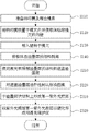
图3为根据本发明的制作键帽的方法的主要流程图;Fig. 3 is the main flowchart of the method for making keycap according to the present invention;
图4为图1中键帽制作的详细流程图;Fig. 4 is the detailed flowchart of keycap making among Fig. 1;
图5为用于图4的制作流程中转印膜的剖面示意图;Fig. 5 is a schematic cross-sectional view of a transfer film used in the production process of Fig. 4;
图6至图11为根据图4的流程图的制作示意图;Fig. 6 to Fig. 11 are the production schematic diagrams according to the flowchart of Fig. 4;
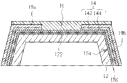
图12为根据本发明中另一较佳具体实施例的键帽的剖面图;Fig. 12 is a cross-sectional view of a keycap according to another preferred embodiment of the present invention;
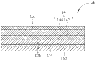
图13为图12中键帽使用的转印膜的剖面示意图。FIG. 13 is a schematic cross-sectional view of a transfer film used in the keycap in FIG. 12 .
具体实施方式 Detailed ways
请参阅图1至图3,图1为根据本发明中一较佳具体实施例的键帽1的俯视图,图2为图1中键帽1沿线X-X的剖面图,图3为根据本发明中制作键帽的方法的主要流程图。如步骤S100所示,该制作键帽的方法主要先以模内转印方法射出形成其上附着有油墨层状结构14的帽体12;如步骤S200所示,该制作键帽的方法接着以高能光学雕刻方法于油墨层状结构14上形成图案16,于本实施例中,图案16为字母A,但本发明不以此为限。最后,如步骤S300所示,该制作键帽的方法再于油墨层状结构14上形成可透光保护层18,覆盖图案16。藉此,键帽1的制作利用模内转印方法提升油墨层状结构14形成于帽体12上的效率,亦提升油墨层状结构14与帽体12的结合强度,解决习知具有图案的键帽的制程耗时、制程变异较大等问题。Please refer to FIGS. 1 to 3. FIG. 1 is a top view of a keycap 1 according to a preferred embodiment of the present invention. FIG. 2 is a cross-sectional view of the keycap 1 along line X-X in FIG. Main flowchart of the method of making keycaps. As shown in step S100, the method for making a keycap mainly uses in-mold transfer printing to form the
于本实施例中,模内转印方法采用模内装饰(In-Mold Decoration)技术中的模内转写(In-Mold Decoration by Roller)方法,高能光学雕刻方法则使用雷射光,其进一步实施说明如后,但本发明均不以此为限。请并参阅图4至图11,图4为键帽1制作的详细流程图,图5为用于图4的制作流程中的转印膜15a的剖面示意图,图6至图11为根据图4的流程图的制作示意图,其中转印膜15a于图6至图8中以粗黑线表示。In this embodiment, the in-mold transfer printing method adopts the in-mold decoration (In-Mold Decoration by Roller) method in the in-mold decoration (In-Mold Decoration) technology, and the high-energy optical engraving method uses laser light, which is further implemented The description is as follows, but the present invention is not limited thereto. Please also refer to Fig. 4 to Fig. 11, Fig. 4 is a detailed flow chart of making keycap 1, Fig. 5 is a schematic cross-sectional view of the
于本实施例中,前述图3中步骤S100由图4中步骤S110、S120、S130及S140实施。如步骤S110所示,该制作键帽的方法包含准备转印膜15a及射出模具2。如图5所示,转印膜15a为层状结构并包含载体152、形成于载体152上的离型层154、形成于离型层154上的遮盖油墨层142、形成于遮盖油墨层142上的可透光油墨层144及形成于可透光油墨层144上的黏胶层156,其中遮盖油墨层142及可透光油墨层144组成油墨层状结构14。如图6及图7所示,射出模具2包含上模22及下模24,上模22及下模24合模后可形成模穴26。In this embodiment, step S100 in FIG. 3 is implemented by steps S110 , S120 , S130 and S140 in FIG. 4 . As shown in step S110 , the method for manufacturing the keycap includes preparing the
如步骤S120所示,该制作键帽的方法接着将转印膜15a放置于模穴26内并使载体152贴附模穴26的内壁。于实际操作中,转印膜15a利用滚轮3对应模穴26放置于下模24上,并可进一步利用真空吸附作用使载体152能密贴于模穴26的内壁,如图6所示;接着,将上模22及下模24合模形成模穴26,如图7所示。As shown in step S120 , in the method for manufacturing the keycap, the
如步骤S130所示,该制作键帽的方法接着射入塑料4于模穴26中,如图8所示。塑料4于模穴26内冷却形成帽体12的同时,油墨层状结构14藉由黏胶层156附着于帽体12上。由于塑料4为加压射入模穴26的,故帽体12与油墨层状结构14的结合强度通常较一般于常温常压下使用喷覆或涂胶黏附的方式形成的结合结构来得强,可避免剥离。另外,于本实施例中,键帽1用于背光键盘,故塑料4采用可透光的塑料,使得帽体12可透光;但本发明不以此为限。As shown in step S130 , the method for manufacturing the keycap is then injected into the plastic 4 into the
模具2打开后,即可自模穴26中取出其上附着有部分转印膜15a的帽体12。如步骤S140所示,藉由离型层154,将载体152自油墨层状结构14上剥离。剥离后,其上附着油墨层状结构14的帽体12的剖面图如图9所示。After the mold 2 is opened, the
于本实施例中,前述图3中步骤S200由图4中的步骤S210、S220实施。如步骤S210所示,该制作键帽的方法接着使用激光束照射油墨层状结构14的遮盖油墨层142;如步骤S220所示,对遮盖油墨层142进行蚀刻以形成图案16,但仍保留可透光油墨层144。蚀刻完成后如图10所示;其中图案16位于帽体12的上表面122。In this embodiment, step S200 in FIG. 3 is implemented by steps S210 and S220 in FIG. 4 . As shown in step S210, the method for making a keycap then uses a laser beam to irradiate the masking
于本实施例中,前述图3中步骤S300由图4中的步骤S310、S320实施。如步骤S310所示,该制作键帽的方法接着于油墨层状结构14上形成第一紫外光胶层19a,如图11所示;其中第一紫外光胶层19a可利用喷覆或其他涂布方式形成于帽体12的上表面122及侧表面124上并覆盖图案16。实际操作中,第一紫外光胶层19a可填满图案16中的镂空区域。如步骤S320所示,该制作键帽的方法接着以紫外光照射第一紫外光胶层19a以硬化形成可透光保护层18,如图2所示。此时,键帽1即完成。In this embodiment, step S300 in FIG. 3 is implemented by steps S310 and S320 in FIG. 4 . As shown in step S310, the method for making a keycap then forms a first ultraviolet
请参阅图12及图13,图12为根据本发明的另一较佳具体实施例的键帽5的剖面图,图13为键帽5使用的转印膜15b的剖面示意图。于本实施例中,转印膜15b相较于转印膜15a还包含第二紫外光胶层19b于离型层154与遮盖油墨层142之间,亦即离型层154、第二紫外光胶层19b、油墨层状结构14及黏胶层156依序形成于载体152上。因此,于前述步骤S140中,载体152藉由离型层154自第二紫外光胶层19b剥离;于前述步骤S210、S220中,激光束将同时蚀刻第二紫外光胶层19b及油墨层状结构14以形成图案16,亦即图案16同时形成于第二紫外光胶层19b及油墨层状结构14上且位于帽体12的上表面122上。由于第二紫外光胶层19b已覆盖帽体12的上表面122及侧表面124,故于前述步骤S310中,第一紫外光胶层19a仅需形成于第二紫外光胶层上19b上且位于帽体12的上表面122上以覆盖图案16,油墨层状结构14即可被第一紫外光胶层19a及第二紫外光胶层19b共同覆盖。并且于前述步骤S320中,紫外光将同时照射第一紫外光胶层19a及第二紫外光胶层19b以硬化形成可透光保护层18,亦即此可透光保护层18包含由紫外光胶层19a、19b硬化形成的紫外光硬化层,同样可提供油墨层状结构14及图案16完整的保护。Please refer to FIG. 12 and FIG. 13 , FIG. 12 is a sectional view of a keycap 5 according to another preferred embodiment of the present invention, and FIG. 13 is a schematic sectional view of a
补充说明的是,实际操作中,转印膜15a、15b不以前述实施例中所揭露的层状结构为限,其可配合实际产品规格的要求而包含更多层,不另赘述。另外,于前述实施例中,键帽1、5均采用紫外光胶层19a、19b硬化形成紫外光硬化层,但本发明不以此为限。实际操作中,其他可形成可透光的保护层的结构亦可作为本发明的可透光保护层18,例如其他硬化树脂。It is supplemented that, in actual operation, the
如前述说明,相较于先前技术,本发明利用模内转印方法大幅节省油墨层状结构附着于帽体的制程时间,亦可增加油墨层状结构与帽体间的结合强度,有效抑制油墨层状结构剥离的可能性。此外,本发明利用转印膜可形成厚度均匀的油墨层状结构,解决习知技术中采用喷覆的方式受限于喷覆角度易造成喷覆厚度不均的问题。另外,当采用的转印膜已包含硬化胶层(如紫外光胶层)时,则于图案形成后,仅需针对图案部分(即帽体的上表面)进行另一硬化胶层覆盖,如此即可达到对油墨层状结构的完整保护功效,并且能减轻硬化胶层涂布整个帽体时可能产生厚度不均的程度。As described above, compared with the prior art, the present invention uses the in-mold transfer printing method to greatly save the process time for the ink layered structure to attach to the cap body, and can also increase the bonding strength between the ink layered structure and the cap body, effectively inhibiting ink Possibility of exfoliation of lamellar structures. In addition, the present invention utilizes the transfer film to form an ink layered structure with uniform thickness, which solves the problem that the spraying method in the prior art is limited by the spraying angle and easily causes uneven spraying thickness. In addition, when the transfer film used already includes a hardened glue layer (such as an ultraviolet light glue layer), after the pattern is formed, it is only necessary to cover the pattern part (ie, the upper surface of the cap body) with another hardened glue layer, so It can achieve a complete protection effect on the layered structure of the ink, and can reduce the degree of uneven thickness that may occur when the hardened adhesive layer coats the entire cap body.
当然,本发明还可有其他多种实施例,在不背离本发明精神及其实质的情况下,熟悉本领域的技术人员可根据本发明作出各种相应的改变和变形,但这些相应的改变和变形都应属于本发明所附的权利要求的保护范围。Certainly, the present invention also can have other multiple embodiments, without departing from the spirit and essence of the present invention, those skilled in the art can make various corresponding changes and deformations according to the present invention, but these corresponding changes All changes and modifications should belong to the scope of protection of the appended claims of the present invention.
Claims (15)
Priority Applications (1)
| Application Number | Priority Date | Filing Date | Title |
|---|---|---|---|
| CN2012100976541A CN102629527A (en) | 2012-04-05 | 2012-04-05 | Key cap and method for making key cap |
Applications Claiming Priority (1)
| Application Number | Priority Date | Filing Date | Title |
|---|---|---|---|
| CN2012100976541A CN102629527A (en) | 2012-04-05 | 2012-04-05 | Key cap and method for making key cap |
Publications (1)
| Publication Number | Publication Date |
|---|---|
| CN102629527A true CN102629527A (en) | 2012-08-08 |
Family
ID=46587768
Family Applications (1)
| Application Number | Title | Priority Date | Filing Date |
|---|---|---|---|
| CN2012100976541A Pending CN102629527A (en) | 2012-04-05 | 2012-04-05 | Key cap and method for making key cap |
Country Status (1)
| Country | Link |
|---|---|
| CN (1) | CN102629527A (en) |
Cited By (25)
| Publication number | Priority date | Publication date | Assignee | Title |
|---|---|---|---|---|
| CN104588274A (en) * | 2013-10-30 | 2015-05-06 | 鸿富锦精密工业(深圳)有限公司 | Film forming device, and film forming method |
| CN104051170B (en) * | 2014-06-09 | 2016-05-11 | 苏州达方电子有限公司 | Keycap and its processing method |
| US9640347B2 (en) | 2013-09-30 | 2017-05-02 | Apple Inc. | Keycaps with reduced thickness |
| US9704670B2 (en) | 2013-09-30 | 2017-07-11 | Apple Inc. | Keycaps having reduced thickness |
| US9704665B2 (en) | 2014-05-19 | 2017-07-11 | Apple Inc. | Backlit keyboard including reflective component |
| US9710069B2 (en) | 2012-10-30 | 2017-07-18 | Apple Inc. | Flexible printed circuit having flex tails upon which keyboard keycaps are coupled |
| US9715978B2 (en) | 2014-05-27 | 2017-07-25 | Apple Inc. | Low travel switch assembly |
| US9761389B2 (en) | 2012-10-30 | 2017-09-12 | Apple Inc. | Low-travel key mechanisms with butterfly hinges |
| US9779889B2 (en) | 2014-03-24 | 2017-10-03 | Apple Inc. | Scissor mechanism features for a keyboard |
| US9793066B1 (en) | 2014-01-31 | 2017-10-17 | Apple Inc. | Keyboard hinge mechanism |
| US9870880B2 (en) | 2014-09-30 | 2018-01-16 | Apple Inc. | Dome switch and switch housing for keyboard assembly |
| US9934915B2 (en) | 2015-06-10 | 2018-04-03 | Apple Inc. | Reduced layer keyboard stack-up |
| US9984834B2 (en) | 2014-05-02 | 2018-05-29 | Darfon Electronics Corp. | Keycap and manufacturing method thereof |
| US9997304B2 (en) | 2015-05-13 | 2018-06-12 | Apple Inc. | Uniform illumination of keys |
| US9997308B2 (en) | 2015-05-13 | 2018-06-12 | Apple Inc. | Low-travel key mechanism for an input device |
| US10128064B2 (en) | 2015-05-13 | 2018-11-13 | Apple Inc. | Keyboard assemblies having reduced thicknesses and method of forming keyboard assemblies |
| CN109148197A (en) * | 2018-07-13 | 2019-01-04 | 大族激光科技产业集团股份有限公司 | A kind of processing method of light-penetration key |
| CN109318644A (en) * | 2018-09-11 | 2019-02-12 | 广东东田转印新材料有限公司 | Double then glue-line transfer films and the product and method that acquisition is adhered to by the transfer film transfer |
| US10211008B2 (en) | 2012-10-30 | 2019-02-19 | Apple Inc. | Low-travel key mechanisms using butterfly hinges |
| US10262814B2 (en) | 2013-05-27 | 2019-04-16 | Apple Inc. | Low travel switch assembly |
| US10310167B2 (en) | 2015-09-28 | 2019-06-04 | Apple Inc. | Illumination structure for uniform illumination of keys |
| US10556408B2 (en) | 2013-07-10 | 2020-02-11 | Apple Inc. | Electronic device with a reduced friction surface |
| US10775850B2 (en) | 2017-07-26 | 2020-09-15 | Apple Inc. | Computer with keyboard |
| US10796863B2 (en) | 2014-08-15 | 2020-10-06 | Apple Inc. | Fabric keyboard |
| US11282659B2 (en) | 2016-08-08 | 2022-03-22 | Apple Inc. | Singulated keyboard assemblies and methods for assembling a keyboard |
Citations (7)
| Publication number | Priority date | Publication date | Assignee | Title |
|---|---|---|---|---|
| US6277312B1 (en) * | 1999-03-11 | 2001-08-21 | Serigraph, Inc. | In-mold decorating with laser etching |
| TWM324843U (en) * | 2006-10-20 | 2008-01-01 | Sunrex Technology Corp | Key cap capable of emitting light |
| CN201107855Y (en) * | 2007-10-26 | 2008-08-27 | 温海涛 | Key structure |
| CN101276699A (en) * | 2007-03-30 | 2008-10-01 | 毅嘉科技股份有限公司 | Method for manufacturing thinned key panel |
| CN101758724A (en) * | 2008-12-22 | 2010-06-30 | 巨腾国际控股有限公司 | Method for making laser engraved pattern on plastic product and product thereof |
| TW201127646A (en) * | 2010-02-05 | 2011-08-16 | Victor Shi-Yueh Sheu | IMR(in-mold roller or in-mold release)/IMF(in-mold forming) making method using a printer printing pre-forming technique |
| CN201946471U (en) * | 2010-11-26 | 2011-08-24 | 苏州达方电子有限公司 | Keyboard |
-
2012
- 2012-04-05 CN CN2012100976541A patent/CN102629527A/en active Pending
Patent Citations (7)
| Publication number | Priority date | Publication date | Assignee | Title |
|---|---|---|---|---|
| US6277312B1 (en) * | 1999-03-11 | 2001-08-21 | Serigraph, Inc. | In-mold decorating with laser etching |
| TWM324843U (en) * | 2006-10-20 | 2008-01-01 | Sunrex Technology Corp | Key cap capable of emitting light |
| CN101276699A (en) * | 2007-03-30 | 2008-10-01 | 毅嘉科技股份有限公司 | Method for manufacturing thinned key panel |
| CN201107855Y (en) * | 2007-10-26 | 2008-08-27 | 温海涛 | Key structure |
| CN101758724A (en) * | 2008-12-22 | 2010-06-30 | 巨腾国际控股有限公司 | Method for making laser engraved pattern on plastic product and product thereof |
| TW201127646A (en) * | 2010-02-05 | 2011-08-16 | Victor Shi-Yueh Sheu | IMR(in-mold roller or in-mold release)/IMF(in-mold forming) making method using a printer printing pre-forming technique |
| CN201946471U (en) * | 2010-11-26 | 2011-08-24 | 苏州达方电子有限公司 | Keyboard |
Cited By (35)
| Publication number | Priority date | Publication date | Assignee | Title |
|---|---|---|---|---|
| US9761389B2 (en) | 2012-10-30 | 2017-09-12 | Apple Inc. | Low-travel key mechanisms with butterfly hinges |
| US10211008B2 (en) | 2012-10-30 | 2019-02-19 | Apple Inc. | Low-travel key mechanisms using butterfly hinges |
| US10254851B2 (en) | 2012-10-30 | 2019-04-09 | Apple Inc. | Keyboard key employing a capacitive sensor and dome |
| US9710069B2 (en) | 2012-10-30 | 2017-07-18 | Apple Inc. | Flexible printed circuit having flex tails upon which keyboard keycaps are coupled |
| US10699856B2 (en) | 2012-10-30 | 2020-06-30 | Apple Inc. | Low-travel key mechanisms using butterfly hinges |
| US10262814B2 (en) | 2013-05-27 | 2019-04-16 | Apple Inc. | Low travel switch assembly |
| US10556408B2 (en) | 2013-07-10 | 2020-02-11 | Apple Inc. | Electronic device with a reduced friction surface |
| US9704670B2 (en) | 2013-09-30 | 2017-07-11 | Apple Inc. | Keycaps having reduced thickness |
| US10804051B2 (en) | 2013-09-30 | 2020-10-13 | Apple Inc. | Keycaps having reduced thickness |
| US10002727B2 (en) | 2013-09-30 | 2018-06-19 | Apple Inc. | Keycaps with reduced thickness |
| US9640347B2 (en) | 2013-09-30 | 2017-05-02 | Apple Inc. | Keycaps with reduced thickness |
| US11699558B2 (en) | 2013-09-30 | 2023-07-11 | Apple Inc. | Keycaps having reduced thickness |
| CN104588274A (en) * | 2013-10-30 | 2015-05-06 | 鸿富锦精密工业(深圳)有限公司 | Film forming device, and film forming method |
| US9793066B1 (en) | 2014-01-31 | 2017-10-17 | Apple Inc. | Keyboard hinge mechanism |
| US9779889B2 (en) | 2014-03-24 | 2017-10-03 | Apple Inc. | Scissor mechanism features for a keyboard |
| US9984834B2 (en) | 2014-05-02 | 2018-05-29 | Darfon Electronics Corp. | Keycap and manufacturing method thereof |
| US9704665B2 (en) | 2014-05-19 | 2017-07-11 | Apple Inc. | Backlit keyboard including reflective component |
| US9715978B2 (en) | 2014-05-27 | 2017-07-25 | Apple Inc. | Low travel switch assembly |
| CN104051170B (en) * | 2014-06-09 | 2016-05-11 | 苏州达方电子有限公司 | Keycap and its processing method |
| US10796863B2 (en) | 2014-08-15 | 2020-10-06 | Apple Inc. | Fabric keyboard |
| US10192696B2 (en) | 2014-09-30 | 2019-01-29 | Apple Inc. | Light-emitting assembly for keyboard |
| US10134539B2 (en) | 2014-09-30 | 2018-11-20 | Apple Inc. | Venting system and shield for keyboard |
| US10128061B2 (en) | 2014-09-30 | 2018-11-13 | Apple Inc. | Key and switch housing for keyboard assembly |
| US10879019B2 (en) | 2014-09-30 | 2020-12-29 | Apple Inc. | Light-emitting assembly for keyboard |
| US9870880B2 (en) | 2014-09-30 | 2018-01-16 | Apple Inc. | Dome switch and switch housing for keyboard assembly |
| US10468211B2 (en) | 2015-05-13 | 2019-11-05 | Apple Inc. | Illuminated low-travel key mechanism for a keyboard |
| US10128064B2 (en) | 2015-05-13 | 2018-11-13 | Apple Inc. | Keyboard assemblies having reduced thicknesses and method of forming keyboard assemblies |
| US9997308B2 (en) | 2015-05-13 | 2018-06-12 | Apple Inc. | Low-travel key mechanism for an input device |
| US9997304B2 (en) | 2015-05-13 | 2018-06-12 | Apple Inc. | Uniform illumination of keys |
| US9934915B2 (en) | 2015-06-10 | 2018-04-03 | Apple Inc. | Reduced layer keyboard stack-up |
| US10310167B2 (en) | 2015-09-28 | 2019-06-04 | Apple Inc. | Illumination structure for uniform illumination of keys |
| US11282659B2 (en) | 2016-08-08 | 2022-03-22 | Apple Inc. | Singulated keyboard assemblies and methods for assembling a keyboard |
| US10775850B2 (en) | 2017-07-26 | 2020-09-15 | Apple Inc. | Computer with keyboard |
| CN109148197A (en) * | 2018-07-13 | 2019-01-04 | 大族激光科技产业集团股份有限公司 | A kind of processing method of light-penetration key |
| CN109318644A (en) * | 2018-09-11 | 2019-02-12 | 广东东田转印新材料有限公司 | Double then glue-line transfer films and the product and method that acquisition is adhered to by the transfer film transfer |
Similar Documents
| Publication | Publication Date | Title |
|---|---|---|
| CN102629527A (en) | Key cap and method for making key cap | |
| TW201338958A (en) | Keycap and method of manufacturing the same | |
| TWI590957B (en) | Mehrschichtkoerper | |
| US20130075941A1 (en) | Method for bonding plastic mold member onto metal housing | |
| CN104582928B (en) | In-mold forming method, in-mold transfer film, and manufacturing method thereof | |
| US9984834B2 (en) | Keycap and manufacturing method thereof | |
| CN102019779A (en) | Three-dimensional pattern production method | |
| CN102201291A (en) | Manufacturing method of keyboard keycap structure | |
| CN102001254A (en) | Forming method of shell with high matt gradually changing effect and electronic product shell | |
| JP2011025660A (en) | Molding method for composite material molding | |
| KR101294422B1 (en) | Method for protecing surface using decoration sheet | |
| CN115674924A (en) | Deep-texture pattern transfer film, transfer material and preparation method thereof | |
| JP5891590B2 (en) | Method for producing transfer foil for in-mold, and method for producing molded product | |
| JP2013132833A (en) | In-mold molding method, in-mold transfer film and in-mold molded article | |
| CN108688366A (en) | The production method of workpiece surface space pattern | |
| TW201332771A (en) | Method of fabricating in-mold film and casing including such in-mold film | |
| KR20130053002A (en) | Uv-roll manufacturing process patterns | |
| CN104723617A (en) | Surface-reinforced fiber product and manufacture method thereof | |
| TWI433738B (en) | Method of manufacturing decorative board for progressive stamping | |
| US9110328B2 (en) | Color filter and manufacturing method for the same | |
| KR20100071247A (en) | Method of combinning laser-engraving and in-mold decoration techniques to laser-engrave pattern on plastic product and the procuct thereof | |
| JP4965313B2 (en) | Pushbutton switch member, plunger sheet and manufacturing method thereof | |
| TW201309468A (en) | Method of manufacturing rolling shaped decorative machine board | |
| TW201400323A (en) | Decoration film and manufacturing method for decorated article | |
| JP5821102B1 (en) | Thermosetting resin molded product and manufacturing method thereof |
Legal Events
| Date | Code | Title | Description |
|---|---|---|---|
| C06 | Publication | ||
| PB01 | Publication | ||
| C10 | Entry into substantive examination | ||
| SE01 | Entry into force of request for substantive examination | ||
| C02 | Deemed withdrawal of patent application after publication (patent law 2001) | ||
| WD01 | Invention patent application deemed withdrawn after publication |
Application publication date: 20120808 |