CN102610954A - Connector assembly - Google Patents

Connector assembly Download PDF

Info

Publication number
CN102610954A
CN102610954A CN2012100706171A CN201210070617A CN102610954A CN 102610954 A CN102610954 A CN 102610954A CN 2012100706171 A CN2012100706171 A CN 2012100706171A CN 201210070617 A CN201210070617 A CN 201210070617A CN 102610954 A CN102610954 A CN 102610954A
Authority
CN
China
Prior art keywords
contact
retainer
tab
holder
contacts
Prior art date
Legal status (The legal status is an assumption and is not a legal conclusion. Google has not performed a legal analysis and makes no representation as to the accuracy of the status listed.)
Granted
Application number
CN2012100706171A
Other languages
Chinese (zh)
Other versions
CN102610954B (en
Inventor
C·D·里特
Current Assignee (The listed assignees may be inaccurate. Google has not performed a legal analysis and makes no representation or warranty as to the accuracy of the list.)
TE Connectivity Corp
Original Assignee
Tyco Electronics Corp
Priority date (The priority date is an assumption and is not a legal conclusion. Google has not performed a legal analysis and makes no representation as to the accuracy of the date listed.)
Filing date
Publication date
Application filed by Tyco Electronics Corp filed Critical Tyco Electronics Corp
Publication of CN102610954A publication Critical patent/CN102610954A/en
Application granted granted Critical
Publication of CN102610954B publication Critical patent/CN102610954B/en
Expired - Fee Related legal-status Critical Current
Anticipated expiration legal-status Critical

Links

Images

Classifications

    • HELECTRICITY
    • H01ELECTRIC ELEMENTS
    • H01RELECTRICALLY-CONDUCTIVE CONNECTIONS; STRUCTURAL ASSOCIATIONS OF A PLURALITY OF MUTUALLY-INSULATED ELECTRICAL CONNECTING ELEMENTS; COUPLING DEVICES; CURRENT COLLECTORS
    • H01R12/00Structural associations of a plurality of mutually-insulated electrical connecting elements, specially adapted for printed circuits, e.g. printed circuit boards [PCB], flat or ribbon cables, or like generally planar structures, e.g. terminal strips, terminal blocks; Coupling devices specially adapted for printed circuits, flat or ribbon cables, or like generally planar structures; Terminals specially adapted for contact with, or insertion into, printed circuits, flat or ribbon cables, or like generally planar structures
    • H01R12/70Coupling devices
    • H01R12/71Coupling devices for rigid printing circuits or like structures
    • H01R12/72Coupling devices for rigid printing circuits or like structures coupling with the edge of the rigid printed circuits or like structures
    • H01R12/722Coupling devices for rigid printing circuits or like structures coupling with the edge of the rigid printed circuits or like structures coupling devices mounted on the edge of the printed circuits
    • H01R12/724Coupling devices for rigid printing circuits or like structures coupling with the edge of the rigid printed circuits or like structures coupling devices mounted on the edge of the printed circuits containing contact members forming a right angle
    • HELECTRICITY
    • H01ELECTRIC ELEMENTS
    • H01RELECTRICALLY-CONDUCTIVE CONNECTIONS; STRUCTURAL ASSOCIATIONS OF A PLURALITY OF MUTUALLY-INSULATED ELECTRICAL CONNECTING ELEMENTS; COUPLING DEVICES; CURRENT COLLECTORS
    • H01R13/00Details of coupling devices of the kinds covered by groups H01R12/70 or H01R24/00 - H01R33/00
    • H01R13/46Bases; Cases
    • H01R13/514Bases; Cases composed as a modular blocks or assembly, i.e. composed of co-operating parts provided with contact members or holding contact members between them
    • HELECTRICITY
    • H01ELECTRIC ELEMENTS
    • H01RELECTRICALLY-CONDUCTIVE CONNECTIONS; STRUCTURAL ASSOCIATIONS OF A PLURALITY OF MUTUALLY-INSULATED ELECTRICAL CONNECTING ELEMENTS; COUPLING DEVICES; CURRENT COLLECTORS
    • H01R13/00Details of coupling devices of the kinds covered by groups H01R12/70 or H01R24/00 - H01R33/00
    • H01R13/646Details of coupling devices of the kinds covered by groups H01R12/70 or H01R24/00 - H01R33/00 specially adapted for high-frequency, e.g. structures providing an impedance match or phase match
    • H01R13/6461Means for preventing cross-talk
    • H01R13/6471Means for preventing cross-talk by special arrangement of ground and signal conductors, e.g. GSGS [Ground-Signal-Ground-Signal]
    • HELECTRICITY
    • H01ELECTRIC ELEMENTS
    • H01RELECTRICALLY-CONDUCTIVE CONNECTIONS; STRUCTURAL ASSOCIATIONS OF A PLURALITY OF MUTUALLY-INSULATED ELECTRICAL CONNECTING ELEMENTS; COUPLING DEVICES; CURRENT COLLECTORS
    • H01R13/00Details of coupling devices of the kinds covered by groups H01R12/70 or H01R24/00 - H01R33/00
    • H01R13/648Protective earth or shield arrangements on coupling devices, e.g. anti-static shielding  
    • H01R13/658High frequency shielding arrangements, e.g. against EMI [Electro-Magnetic Interference] or EMP [Electro-Magnetic Pulse]
    • H01R13/6581Shield structure
    • H01R13/6585Shielding material individually surrounding or interposed between mutually spaced contacts
    • H01R13/6586Shielding material individually surrounding or interposed between mutually spaced contacts for separating multiple connector modules

Landscapes

  • Details Of Connecting Devices For Male And Female Coupling (AREA)

Abstract

A connector assembly (102) includes contact modules (122) each having a dielectric frame (240) and contacts (124) held by the dielectric frame. The contacts are arranged along a contact plane (278) within the frame. The dielectric frame includes frame members connected (264) by connecting segments (266). The frame has windows (270) between the frame members located between adjacent contacts. Holders (120) support corresponding contact modules. The holders are electrically grounded. The holders each have a support wall (224) and tabs (272,274) that extend outward from the support wall. The contact modules are coupled to the holders such that the tabs are received in the windows to provide shielding within the contact modules. The holders are coupled together such that the contact modules are stacked together with the tabs of at least some of the holders that extend into the contact module held by the adjacent holder and across the contact plane defined by the contact module of the adjacent holder.

Description

连接器组件connector assembly

技术领域 technical field

本发明涉及一种屏蔽的电连接器组件。The present invention relates to a shielded electrical connector assembly.

背景技术 Background technique

一些电气系统利用电连接器以使两电路板如母板和子插件板互连。在一些系统中,为电连接该电连接器,中板电路板在其相对的前部和后部设置有前部插头连接器和后部插头连接器。其它的系统通过直接连接电连接器在电路板上而不使用中板电路板来电连接电路板。Some electrical systems utilize electrical connectors to interconnect two circuit boards, such as a motherboard and a daughterboard. In some systems, to electrically connect the electrical connectors, the midplane circuit board is provided with front and rear header connectors on opposite front and rear portions thereof. Other systems electrically connect circuit boards by directly connecting electrical connectors on the circuit boards without using a midplane circuit board.

然而,由于速度和性能要求的增加,已知的电连接器被证明是不够的。在已知的电气系统中,信号损失和/或信号衰减是个问题。另外,希望增加电连接器的密度以增加电气系统吞吐量,而不明显增加电连接器的尺寸,并且在某些情况下,减小电连接器的尺寸。如此的密度增加和/或尺寸减小将对性能造成进一步的压力。However, known electrical connectors have proven insufficient due to increased speed and performance requirements. In known electrical systems, signal loss and/or signal attenuation is a problem. Additionally, it is desirable to increase the density of electrical connectors to increase electrical system throughput without significantly increasing, and in some cases reducing, the size of the electrical connectors. Such increased density and/or reduced size will put further pressure on performance.

为提升性能,一些已知系统利用屏蔽来降低电连接器的触头之间的干扰。然而,已知系统中利用的屏蔽不是没有缺点。例如,屏蔽是选择性地沿着信号通路来利用的,由这些部分信号通路仍保持未屏蔽。To improve performance, some known systems utilize shielding to reduce interference between the contacts of the electrical connector. However, the shielding utilized in known systems is not without drawbacks. For example, shielding is selectively utilized along signal paths, whereby portions of the signal path remain unshielded.

需要一种具有有效屏蔽以满足特殊性能的要求的连接器组件。There is a need for a connector assembly with effective shielding to meet specific performance requirements.

发明内容 Contents of the invention

根据本发明,连接器组件包括触头模块,每个触头模块具有绝缘的框架和被该框架保持的触头。该触头配置为沿着框架内部的触头平面。该框架包括被连接段连接的框架构件,并且该框架具有位于相邻触头之间的框架构件之间的窗口。保持器支撑相应的触头模块,并且该保持器电接地。该保持器每个具有支撑壁以及从该支撑壁向外延伸的凸片。该触头模块连接至该保持器,以使该凸片被收纳在窗口中以在触头模块内部提供屏蔽。该保持器连接在一起以使触头模块堆叠在一起,并且每个触头模块的凸片延伸进由相邻保持器所保持的触头模块中,并穿过被由相邻保持器所保持的触头模块限定的触头平面。According to the present invention, a connector assembly includes contact modules each having an insulating frame and contacts held by the frame. The contacts are arranged along a contact plane inside the frame. The frame includes frame members connected by connecting segments, and the frame has windows between the frame members between adjacent contacts. A holder supports a corresponding contact module, and the holder is electrically grounded. The holders each have a support wall and a tab extending outwardly from the support wall. The contact module is connected to the holder such that the tab is received in the window to provide shielding inside the contact module. The holders are joined together so that the contact modules are stacked together, and the tabs of each contact module extend into and through the contact modules held by the adjacent holder. The contact module defines the contact plane.

附图说明 Description of drawings

图1是表示插头组件和插座组件的连接器系统的透视图;Figure 1 is a perspective view of a connector system showing a plug assembly and a receptacle assembly;

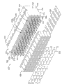
图2是图1所示的插座组件的分解图;Fig. 2 is an exploded view of the socket assembly shown in Fig. 1;

图3是表示多个触头模块和多个保持器的插座组件的一部分的一个侧面的正透视图;3 is a front perspective view of one side of a portion of a receptacle assembly showing a plurality of contact modules and a plurality of retainers;

图4是图3所示的触头模块和保持器的另一侧面的正透视图;4 is a front perspective view of another side of the contact module and holder shown in FIG. 3;

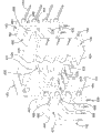
图5是用于一个触头模块的引线框的正透视图;Figure 5 is a front perspective view of a lead frame for a contact module;

图6是一个保持器的第一侧面的正透视图;Figure 6 is a front perspective view of a first side of a retainer;

图7是一个保持器的另一侧面的正透视图;Figure 7 is a front perspective view of the other side of a retainer;

图8是一个保持器以及相应触头模块的一个侧面的分解图;Figure 8 is an exploded view of a side of a holder and corresponding contact module;

图9是一个保持器以及相应触头模块的另一侧面的分解图;Figure 9 is an exploded view of a retainer and the other side of the corresponding contact module;

图10示出将被配合至插头组件的插座组件;Figure 10 shows a receptacle assembly to be mated to a plug assembly;

图11是用于插头组件的保持器和触头模块的一部分的一个侧面的局部分解图;Figure 11 is a partial exploded view of one side of a portion of a retainer and contact module for a plug assembly;

图12是用于插头组件的保持器和触头模块的一部分的另一侧面的局部分解图;Figure 12 is another side partial exploded view of a portion of the retainer and contact module for the header assembly;

图13是插头组件的一个侧面的正透视图;Figure 13 is a front perspective view of one side of the plug assembly;

图14是插头组件的另一侧面的正透视图。Figure 14 is a front perspective view of the other side of the plug assembly.

具体实施方式 Detailed ways

图1是连接器系统100的示例性实施例的透视图,其示出了可直接配合在一起的插座组件102和插头组件104。该插座组件102和/或该插头组件104在下文中被单独称为“连接器组件”或者共同称为“连接器组件”。该插座组件102和插头组件104每个都电连接至各自的电路板106和电路板108。该插座组件102和插头组件104用来在可分离的配合接口彼此电连接该电路板106和电路板108。在示例性实施例中,当该插座组件102和插头组件104配合时该电路板106和电路板108彼此被取向为共面。在替代的实施例中,该电路板106和电路板108的替代的取向是可能的。例如,该电路板106和电路板108可彼此平行,但是彼此并不共面。在一些替代实施例中,该电路板106和电路板108可彼此垂直。1 is a perspective view of an exemplary embodiment of a connector system 100 showing a receptacle assembly 102 and a header assembly 104 that may be mated directly together. The receptacle assembly 102 and/or the plug assembly 104 are hereinafter referred to individually as a "connector assembly" or collectively as a "connector assembly". The receptacle assembly 102 and header assembly 104 are each electrically connected to a respective circuit board 106 and circuit board 108 . The socket assembly 102 and header assembly 104 are used to electrically connect the circuit board 106 and the circuit board 108 to each other at a separable mating interface. In the exemplary embodiment, the circuit board 106 and circuit board 108 are oriented coplanar with each other when the receptacle assembly 102 and header assembly 104 are mated. In alternate embodiments, alternate orientations of the circuit board 106 and circuit board 108 are possible. For example, the circuit board 106 and the circuit board 108 may be parallel to each other, but not coplanar with each other. In some alternative embodiments, the circuit board 106 and the circuit board 108 may be perpendicular to each other.

配合轴110延伸穿过插座组件102和插头组件104。该插座组件102和插头组件104在平行于并沿着该配合轴110的方向配合在一起。在示例性实施例中,该电路板106和电路板108两者大致平行于该配合轴110延伸。The mating shaft 110 extends through the receptacle assembly 102 and the header assembly 104 . The receptacle assembly 102 and plug assembly 104 are mated together in a direction parallel to and along the mating axis 110 . In the exemplary embodiment, both the circuit board 106 and the circuit board 108 extend generally parallel to the mating axis 110 .

在示例性实施例中,该插座组件102是模块化设计的,并且可包括连接在一起以制成该插座组件102的任意数量的部件,这取决于具体的应用。该插座组件102包括屏蔽体118,其在该屏蔽体118的周围和内部提供选择性的屏蔽。该插座组件102包括多个保持器120以支撑多个触头模块122(图2所示)。该保持器120限定了该屏蔽体118。例如,该保持器120可为压铸件,其由金属材料通过压印成形,金属化或其它方式形成,以便为被保持器120所保持的触头模块122提供屏蔽。In an exemplary embodiment, the socket assembly 102 is of modular design and may include any number of components that are connected together to make the socket assembly 102, depending on the particular application. The receptacle assembly 102 includes a shield 118 that provides selective shielding around and within the shield 118 . The receptacle assembly 102 includes a plurality of holders 120 to support a plurality of contact modules 122 (shown in FIG. 2 ). The retainer 120 defines the shield 118 . For example, the holder 120 can be a die-casting piece, which is formed from a metal material by stamping, metallization or otherwise, so as to provide shielding for the contact module 122 held by the holder 120 .

每个触头模块122包括多个插座触头124。在图示的实施例中,该插座触头124构成管座触头,然而在替代的实施例中可使用其它类型的触头,如针式触头,弹簧杆,音叉型触头,刀片型触头以及其它类似触头。Each contact module 122 includes a plurality of receptacle contacts 124 . In the illustrated embodiment, the receptacle contacts 124 constitute socket contacts, however other types of contacts may be used in alternative embodiments, such as pin contacts, spring rods, tuning fork-type contacts, blade-type contacts Contacts and other similar contacts.

该保持器120是模块化设计的,并且可设置任意数量的保持器120并使其堆叠在一起以形成该屏蔽体118。从而该屏蔽体118由多个单独的屏蔽部件限定,这些单独的屏蔽部件耦接在一起以形成为该插座触头124提供电屏蔽的单体。增加更多的保持器120以增加触头模块122的数量并因此增加插座触头124的数量。或者,提供较少的保持器120以减少触头模块122的数量,并因此减少插座触头124的数量。The holder 120 is of modular design and any number of holders 120 can be provided and stacked together to form the shield 118 . The shield body 118 is thus defined by a plurality of individual shield components that are coupled together to form a single body that provides electrical shielding for the receptacle contacts 124 . Adding more retainers 120 increases the number of contact modules 122 and thus socket contacts 124 . Alternatively, fewer retainers 120 are provided to reduce the number of contact modules 122 and thus reduce the number of receptacle contacts 124 .

该插座组件102包括位于该插座组件102配合端128的配合壳体126。该插座触头124被收纳在该配合壳体126中,并被保持其中以与插头组件104配合。该插座触头124被设置为行与列的阵列。可在行与列中设置任意数量的插座触头124。可选地,该插座触头124可为配置为差分对129的信号触头。每个差分对129中的插座触头124设置在公共行中,并且作为不同的触头模块122的一部分并被保持在不同的保持器120中。该保持器120提供每一个差分对129之间的屏蔽,这将在下面进行详细描述。可选地,每个差分对129中的插座触头124具有相同的长度,并因此具有非失真设计。The receptacle assembly 102 includes a mating housing 126 at a mating end 128 of the receptacle assembly 102 . The receptacle contacts 124 are received in the mating housing 126 and retained therein for mating with the header assembly 104 . The socket contacts 124 are arranged in an array of rows and columns. Any number of socket contacts 124 may be arranged in rows and columns. Optionally, the receptacle contacts 124 may be signal contacts configured as differential pairs 129 . The receptacle contacts 124 in each differential pair 129 are arranged in a common row and are part of different contact modules 122 and held in different holders 120 . The keeper 120 provides shielding between each differential pair 129, which will be described in detail below. Optionally, the receptacle contacts 124 in each differential pair 129 are of the same length and thus have a non-distorting design.

该插座组件102包括被安装在电路板106上的安装端130。可选地,该安装端130大体上可垂直于配合端128。或者,其它配置也是可能的,例如使安装端130大体上平行于配合端128。该屏蔽体118沿着安装端130设置并暴露以电接地至该电路板106,例如通过导电衬垫200的方式,然而在替代的实施例中其它的共电的装置或部件也可使用。该屏蔽体118沿着配合端128设置并暴露以电接地至该插头组件104,例如通过导电衬垫202的方式,然而在替代的实施例中其它的共电的装置或部件也可使用。例如,该插座组件102可使用接地触头或者接地夹具。The socket assembly 102 includes a mounting end 130 that is mounted on the circuit board 106 . Optionally, the mounting end 130 may be substantially perpendicular to the mating end 128 . Alternatively, other configurations are possible, such as having the mounting end 130 generally parallel to the mating end 128 . The shield 118 is disposed along the mounting end 130 and is exposed to be electrically grounded to the circuit board 106 , such as by means of a conductive pad 200 , although other electrical common devices or components may be used in alternative embodiments. The shield 118 is disposed along the mating end 128 and is exposed to be electrically grounded to the header assembly 104 , such as by way of the conductive pad 202 , although other electrical common devices or components may be used in alternative embodiments. For example, the receptacle assembly 102 may use ground contacts or ground clamps.

该插座组件102包括位于该插座组件102的相对末端的末端保持器132,134。该末端保持器132,134与设置在该末端保持器132,134之间的中间保持器120不同,这将在下面进行详细描述。该末端保持器132,134也限定了该屏蔽体118的一部分。该末端保持器132,134保持触头模块122在其中。The socket assembly 102 includes end retainers 132 , 134 at opposite ends of the socket assembly 102 . The end retainers 132, 134 are distinct from the intermediate retainer 120 disposed between the end retainers 132, 134, as will be described in detail below. The end retainers 132 , 134 also define a portion of the shield 118 . The end retainers 132, 134 retain the contact modules 122 therein.

在示例性实施例中,该插头组件104是模块化设计的,并且可包括连接在一起以制成该插头组件104的任意数量的部件,这取决于具体的应用。该插头组件104包括屏蔽体138,其在该屏蔽体138的周围和内部提供选择性的屏蔽。该插头组件104包括多个保持器140以支撑多个触头模块142(图11所示)。该保持器140限定了该屏蔽体138。每个触头模块142包括多个插头触头144。在图示的实施例中,该插头触头144构成针式触头,然而在替代实施例中可使用其它类型的触头,如管座触头,弹簧杆,音叉型触头,刀片型触头以及其它类似触头。可设置任意数量的保持器140。In an exemplary embodiment, the header assembly 104 is of modular design and may include any number of components that are connected together to make the header assembly 104, depending on the particular application. The header assembly 104 includes a shield 138 that provides selective shielding around and within the shield 138 . The header assembly 104 includes a plurality of holders 140 to support a plurality of contact modules 142 (shown in FIG. 11 ). The retainer 140 defines the shield 138 . Each contact module 142 includes a plurality of header contacts 144 . In the illustrated embodiment, the plug contacts 144 constitute pin contacts, however other types of contacts may be used in alternative embodiments, such as socket contacts, spring rods, tuning fork-type contacts, blade-type contacts. head and other similar contacts. Any number of retainers 140 may be provided.

该插头组件104包括位于该插头组件104的配合端148的配合壳体146。该配合壳体146由绝缘的材料制成,并使插头触头144与保持器140隔开。该插头触头144被收纳在相应的配合壳体146中,并被保持其中以与插座组件102的插座触头124配合。可选地,该插头触头144可为配置为差分对149的信号触头。每个差分对149中的插头触头144被设置在同一行中,并且作为不同的触头模块142的一部分并被保持在不同的保持器140中。可选地,每个差分对149中的插头触头144具有相同的长度,并因此具有非失真设计。The header assembly 104 includes a mating housing 146 at a mating end 148 of the header assembly 104 . The mating housing 146 is made of an insulating material and separates the header contacts 144 from the retainer 140 . The header contacts 144 are received in corresponding mating housings 146 and retained therein to mate with the receptacle contacts 124 of the receptacle assembly 102 . Alternatively, the header contacts 144 may be signal contacts configured as differential pairs 149 . The header contacts 144 in each differential pair 149 are arranged in the same row and are part of different contact modules 142 and held in different holders 140 . Optionally, the header contacts 144 in each differential pair 149 are of the same length and thus have a non-distorting design.

该插头组件104包括被安装在电路板108上的安装端150。可选地,该安装端150可大体上垂直于配合端148。或者,其它结构也是可能的,例如使安装端150大体上平行于配合端148。该屏蔽体138沿着安装端150设置以电接地至该电路板108,例如通过导电衬垫204的方式,然而在替代的实施例中其它的共电的装置或部件也可使用。该屏蔽体138在配合端148暴露以组合该导电衬垫202从而与该屏蔽体138和插座组件102的屏蔽体118共电。在替代的实施例中该屏蔽体118,138可通过其它部件共电。The header assembly 104 includes a mounting end 150 that is mounted on the circuit board 108 . Optionally, the mounting end 150 may be substantially perpendicular to the mating end 148 . Alternatively, other configurations are possible, such as having the mounting end 150 substantially parallel to the mating end 148 . The shield 138 is disposed along the mounting end 150 to be electrically grounded to the circuit board 108 , such as by way of the conductive pad 204 , although other electrical common devices or components may be used in alternative embodiments. The shield 138 is exposed at the mating end 148 to combine the conductive pad 202 to share electricity with the shield 138 and the shield 118 of the receptacle assembly 102 . In alternative embodiments the shields 118, 138 may be electrically shared by other components.

在示例性实施例中,该插头组件104包括位于该插头组件104的相对末端的末端保持器152,154。该末端保持器152,154与设置在该末端保持器152,154之间的中间保持器140不同,这将在下面进行详细描述。该末端保持器152,154也限定了该屏蔽体138的一部分。该末端保持器152,154保持触头模块142在其中。当组装时,该保持器140和末端保持器152,154相互配合以在配合端148限定装载腔156。该装载腔156配置为收纳插座组件102的一部分,例如配合壳体126。该插座组件102被沿着配合轴110(图10所示)装入该装载腔156中。该插座触头124在该装载腔156中与该插头触头144配合。在示例性实施例中,连接器系统100可被反转,其中该插座组件102可在两个不同的取向(如彼此成180°)被收纳在插头组件104中。该配合接口的尺寸,形状和/或取向使得插座组件102可前部朝上或前部朝下被装入该装载腔156。In the exemplary embodiment, the header assembly 104 includes end retainers 152 , 154 at opposite ends of the header assembly 104 . The end retainers 152, 154 are distinct from the intermediate retainer 140 disposed between the end retainers 152, 154, as will be described in detail below. The end retainers 152 , 154 also define a portion of the shield 138 . The end retainers 152, 154 retain the contact modules 142 therein. When assembled, the retainer 140 and end retainers 152 , 154 cooperate to define a loading cavity 156 at the mating end 148 . The loading cavity 156 is configured to receive a portion of the receptacle assembly 102 , such as the mating housing 126 . The socket assembly 102 is loaded into the loading cavity 156 along the mating axis 110 (shown in FIG. 10 ). The receptacle contacts 124 mate with the header contacts 144 in the loading cavity 156 . In an exemplary embodiment, the connector system 100 can be reversed, wherein the receptacle assembly 102 can be received in the header assembly 104 in two different orientations (eg, 180° from each other). The mating interface is sized, shaped and/or oriented such that the receptacle assembly 102 can be loaded into the loading cavity 156 either front-up or front-down.

图2是该插座组件102的分解图。图2示出了装入相应的保持器120中的触头模块122。该配合壳体126正准备安装至保持器120。图2还示出了配置为连接至该插座组件102的安装端130的导电衬垫200和配置为连接至该配合端128的导电衬垫202。FIG. 2 is an exploded view of the socket assembly 102 . FIG. 2 shows the contact modules 122 loaded into corresponding holders 120 . The mating housing 126 is ready for installation to the holder 120 . FIG. 2 also shows a conductive pad 200 configured to connect to the mounting end 130 of the receptacle assembly 102 and a conductive pad 202 configured to connect to the mating end 128 .

该导电衬垫200限定了该插座组件102的屏蔽体118与该电路板106之间的接地通路(图1所示)。例如,该导电衬垫200可组合并电连接至该保持器120以使该保持器120至该电路板106上的接地电路共电。该导电衬垫202限定了该插座组件102的屏蔽体118与该插头组件104的屏蔽体138(图1所示)之间的接地通路(图1所示)。例如,该导电衬垫202可组合并电连接至该保持器120和保持器140(图1所示)以与该保持器120至该保持器140共电。The conductive gasket 200 defines a ground path between the shield 118 of the receptacle assembly 102 and the circuit board 106 (shown in FIG. 1 ). For example, the conductive pad 200 may be combined and electrically connected to the holder 120 to share electrical power from the holder 120 to a ground circuit on the circuit board 106 . The conductive gasket 202 defines a ground path (shown in FIG. 1 ) between the shield 118 of the receptacle assembly 102 and the shield 138 (shown in FIG. 1 ) of the header assembly 104 . For example, the conductive pad 202 can be combined and electrically connected to the holder 120 and the holder 140 (shown in FIG. 1 ) to share electricity with the holder 120 to the holder 140 .

该插座组件102包括连接至每个保持器120和末端保持器132,134的保持器206。该保持器206将每个保持器120和末端保持器132,134固定在一起。可选地,该保持器120和末端保持器132,134可被直接地彼此连接,例如使用集成至该保持器120和末端保持器132,134中的对准或固定部件。一旦保持在一起,该保持器120和末端保持器132,134形成该屏蔽体118,其在结构上支撑该触头模块122并电屏蔽该插座触头124。The socket assembly 102 includes a retainer 206 connected to each retainer 120 and end retainers 132 , 134 . The retainer 206 secures each retainer 120 and end retainers 132, 134 together. Alternatively, the holder 120 and end holders 132 , 134 may be connected directly to each other, for example using alignment or securing features integrated into the holder 120 and end holders 132 , 134 . Once held together, the retainer 120 and end retainers 132 , 134 form the shield 118 that structurally supports the contact module 122 and electrically shields the receptacle contacts 124 .

该插座触头124包括配合部分212,其向前延伸以与该插头触头144(图1所示)配合。该配合部分212配置为被装入该配合壳体126中。该插座触头124包括由触头尾部214限定的安装部分,其向下延伸以安装至该电路板106。该触头尾部214为柔性针,如针眼触头,其可被压配合进该电路板106的镀孔中。The receptacle contacts 124 include mating portions 212 that extend forwardly to mate with the header contacts 144 (shown in FIG. 1 ). The mating portion 212 is configured to fit into the mating housing 126 . The receptacle contacts 124 include mounting portions defined by contact tails 214 that extend downwardly for mounting to the circuit board 106 . The contact tails 214 are flexible pins, such as eye-of-needle contacts, that can be press-fit into plated holes of the circuit board 106 .

图3和4是该插座组件102一部分的不同侧面的正透视图,其示出多个触头模块122和多个保持器120。在示例性实施例中,与末端保持器132,134(图1所示)相对的中间保持器120彼此相同。或者,该保持器120可彼此不同。例如,该保持器120可构成对,几对保持器120具有不同的特征,并且这几对被配置为与其它几对相配合。3 and 4 are front perspective views of different sides of a portion of the receptacle assembly 102 showing the plurality of contact modules 122 and the plurality of retainers 120 . In the exemplary embodiment, the intermediate retainers 120 opposite the end retainers 132, 134 (shown in FIG. 1 ) are identical to each other. Alternatively, the holders 120 may be different from each other. For example, the retainers 120 may form pairs, several pairs of retainers 120 having different characteristics, and the pairs configured to mate with other pairs.

每个保持器120包括配置为支撑多个触头模块122的主体。该主体限定了该屏蔽体118(图1所示)的一部分。该保持器120包括前部220和后部221。该保持器120包括底部222和顶部223。在图示的实施例中,每个保持器120支撑两个触头模块122。在替代的实施例中,可通过特殊的保持器120来支撑更多或更少的触头模块122。Each holder 120 includes a body configured to support a plurality of contact modules 122 . The body defines a portion of the shield 118 (shown in FIG. 1 ). The holder 120 includes a front portion 220 and a rear portion 221 . The holder 120 includes a bottom 222 and a top 223 . In the illustrated embodiment, each holder 120 supports two contact modules 122 . In alternative embodiments, more or fewer contact modules 122 may be supported by special holders 120 .

在示例性实施例中,该保持器120由导电材料制成。例如,该保持器120可由金属材料印模压铸而成。或者,该保持器120可由已经金属化或者覆盖有金属层的塑料材料压印形成或制造而成。通过使该保持器120由导电材料制成,该保持器120可为该插座组件102限定一接地屏蔽。在将触头模块122组装在一起之前,分离的接地屏蔽不需要被设置和耦接到触头模块122。而是,该保持器120限定接地屏蔽,并仍作为屏蔽体118的一部分支撑该触头模块122。当该保持器120被组合在一起时,该保持器120限定该插座组件102的屏蔽体118。该保持器120可通过将单独的保持器120彼此连接或者通过使用分离部件如保持器206(图2所示)而组合在一起。该保持器120被组合在一起,以使该触头模块122彼此平行地堆叠。部分的保持器120可在各自的触头模块122之间延伸,以在它们之间提供电屏蔽。In an exemplary embodiment, the holder 120 is made of a conductive material. For example, the retainer 120 may be die-cast from a metallic material. Alternatively, the holder 120 may be stamped or manufactured from a plastic material that has been metallized or covered with a metal layer. By making the retainer 120 from a conductive material, the retainer 120 can define a ground shield for the receptacle assembly 102 . A separate ground shield need not be provided and coupled to the contact modules 122 prior to assembling the contact modules 122 together. Instead, the retainer 120 defines a ground shield and still supports the contact module 122 as part of the shield body 118 . When the retainers 120 are brought together, the retainers 120 define the shield 118 of the receptacle assembly 102 . The holders 120 may be combined by connecting individual holders 120 to each other or by using separate components such as holder 206 (shown in FIG. 2 ). The holders 120 are grouped together such that the contact modules 122 are stacked parallel to each other. Portions of the retainer 120 may extend between respective contact modules 122 to provide electrical shielding therebetween.

该保持器120在各自的触头模块122之间和周围提供电屏蔽。该保持器120提供屏蔽防止电磁干扰(EMI)和/或射频干扰(RFI)。该保持器120也可对其它类型的干扰提供屏蔽。该保持器120在触头模块122的周围和/或在该触头模块122的插座触头124之间提供屏蔽以控制电特性,如该插座触头124的阻抗控制,串扰控制以及类似控制。例如,通过使该保持器120电接地,该保持器120为该触头模块122提供屏蔽以控制其电特性。The retainer 120 provides electrical shielding between and around respective contact modules 122 . The holder 120 provides shielding from electromagnetic interference (EMI) and/or radio frequency interference (RFI). The holder 120 may also provide shielding from other types of interference. The retainer 120 provides shielding around the contact module 122 and/or between the receptacle contacts 124 of the contact module 122 to control electrical characteristics, such as impedance control of the receptacle contacts 124, crosstalk control, and the like. For example, by electrically grounding the holder 120, the holder 120 provides shielding for the contact module 122 to control its electrical characteristics.

在图示的实施例中,该保持器120沿着该触头模块122的顶部,后部,前部和底部提供屏蔽。可选地,该保持器120可在任意或者全部触头模块122之间和/或在任意或者全部插座触头124之间提供屏蔽。例如,如在图示的实施例中,每个保持器120包括支撑壁224。该支撑壁224设置在被保持器120保持的一对触头模块122之间。该支撑壁224提供被保持器120保持的一对触头模块122之间的屏蔽。可选地,该支撑壁224可大体上设置在该保持器120相对的侧面226,228之间的中央。该保持器120包括在第一侧面226的第一插座腔230和在第二侧面228的第二插座腔232。每个插座腔230,232收纳一个触头模块122在其中。该触头模块122装入相应的插座腔230,232中,以使该触头模块122抵靠支撑壁224。或者,该插座腔230和/或插座腔232可收纳多于一个的触头模块122。在其它替代的实施例中,只在每个保持器120中设置一个插座腔,该插座腔收纳一个,两个或更多触头模块122在其中。In the illustrated embodiment, the retainer 120 provides shielding along the top, rear, front and bottom of the contact module 122 . Optionally, the retainer 120 may provide shielding between any or all contact modules 122 and/or between any or all receptacle contacts 124 . For example, as in the illustrated embodiment, each holder 120 includes a support wall 224 . The support wall 224 is provided between the pair of contact modules 122 held by the holder 120 . The support wall 224 provides shielding between the pair of contact modules 122 held by the holder 120 . Optionally, the support wall 224 may be disposed generally centrally between opposing sides 226 , 228 of the holder 120 . The holder 120 includes a first socket cavity 230 on the first side 226 and a second socket cavity 232 on the second side 228 . Each socket cavity 230, 232 receives a contact module 122 therein. The contact module 122 fits into the corresponding socket cavity 230 , 232 such that the contact module 122 abuts against the support wall 224 . Alternatively, the receptacle cavity 230 and/or the receptacle cavity 232 can accommodate more than one contact module 122 . In other alternative embodiments, only one receptacle cavity is provided in each holder 120, which receives one, two or more contact modules 122 therein.

每个触头模块122包括包围插座触头124的绝缘的框架240。在示例性实施例中,该插座触头124最初被保持在一起作为引线框242(图5所示),其过模制有绝缘的材料以形成该绝缘的框架240。在该引线框242被过模制后,该插座触头124彼此被分离。可利用不同于过模制该引线框的制造工艺以形成该触头模块122,例如将该插座触头124装入形成的绝缘的体中。Each contact module 122 includes an insulating frame 240 surrounding the receptacle contacts 124 . In an exemplary embodiment, the receptacle contacts 124 are initially held together as a lead frame 242 (shown in FIG. 5 ) that is overmolded with an insulating material to form the insulating frame 240 . After the leadframe 242 is overmolded, the receptacle contacts 124 are separated from each other. Manufacturing processes other than overmolding the leadframe may be utilized to form the contact module 122, such as encapsulating the receptacle contacts 124 into a formed insulating body.

每个插座触头124包括在其一个末端的一个触头尾部214,以及在其相对末端的一个配合部分212。该配合部分212和触头尾部214为该插座触头124的从该绝缘的框架240延伸的部分。在示例性实施例中,该配合部分212相对于该触头尾部214大致垂直地延伸。该插座触头124的内部部分或者包住的部分在该绝缘的框架240内在配合部分212和触头尾部214之间过渡。在其它实施例中,该配合部分212相对于该触头尾部214可以是不垂直的。例如,该配合部分212可与该触头尾部214平行。可选地,该配合部分212可与该触头尾部214轴向对准。Each receptacle contact 124 includes a contact tail 214 at one end thereof, and a mating portion 212 at an opposite end thereof. The mating portion 212 and contact tail 214 are portions of the receptacle contacts 124 that extend from the insulating frame 240 . In the exemplary embodiment, the mating portion 212 extends generally perpendicularly relative to the contact tail 214 . The inner or enveloped portion of the receptacle contact 124 transitions within the insulating frame 240 between the mating portion 212 and the contact tail 214 . In other embodiments, the mating portion 212 may not be perpendicular relative to the contact tail 214 . For example, the mating portion 212 can be parallel to the contact tail 214 . Optionally, the mating portion 212 may be axially aligned with the contact tail 214 .

该绝缘的框架240具有外壁,该外壁包括前壁250,与该前壁250大致相对的后壁252,顶壁254以及与该顶壁254大致相对的底壁256。可选地,该绝缘的框架240可包括在该顶壁254和该后壁252之间延伸的倾斜壁258。该倾斜壁258相对于该顶壁254和该后壁252成角度。在示例性实施例中,该前壁250和后壁252彼此平行,并且该顶壁254和底壁256彼此平行并且相对于该前壁250和后壁252大致垂直。该插座触头124的配合部分212从该绝缘的框架240的前壁250延伸。该插座触头124的触头尾部214从该绝缘的框架240的底壁256延伸。在替代实施例中其它的结构是可能的。The insulating frame 240 has outer walls including a front wall 250 , a rear wall 252 generally opposite the front wall 250 , a top wall 254 , and a bottom wall 256 generally opposite the top wall 254 . Optionally, the insulating frame 240 may include a sloped wall 258 extending between the top wall 254 and the rear wall 252 . The sloped wall 258 is angled relative to the top wall 254 and the rear wall 252 . In the exemplary embodiment, the front wall 250 and the rear wall 252 are parallel to each other, and the top wall 254 and the bottom wall 256 are parallel to each other and generally perpendicular relative to the front wall 250 and the rear wall 252 . The mating portion 212 of the receptacle contact 124 extends from the front wall 250 of the insulating frame 240 . The contact tails 214 of the receptacle contacts 124 extend from the bottom wall 256 of the insulating frame 240 . Other configurations are possible in alternative embodiments.

该绝缘的框架240包括第一侧面260以及大致与该第一侧面260相对的第二侧面262。该第一侧面260和第二侧面262大致平行于该保持器120的侧面226,228。该绝缘的框架240具有第一侧面260和第二侧面262之间的宽度263。该第一侧面260表示该绝缘的框架240的暴露在保持器120外部的外侧面。该第二侧面262表示该绝缘的框架240的抵靠支撑壁224装入相应的插座腔230中的内侧面。在示例性实施例中,可使用两种类型的触头模块122,即“A”模块和“B”模块。可选地,该A模块和B模块可为彼此镜像的形式。在如图3和4所示的取向中,从图3和4所示的透视图来看,该A模块具有在右侧的第一侧面260和在左侧的第二侧面262(例如抵靠该支撑壁224)。相比之下,从图3和4所示的透视图来看,该B模块具有在左侧的第一侧面260和在右侧的第二侧面262(例如抵靠该支撑壁224)。The insulating frame 240 includes a first side 260 and a second side 262 substantially opposite to the first side 260 . The first side 260 and the second side 262 are generally parallel to the sides 226 , 228 of the holder 120 . The insulating frame 240 has a width 263 between the first side 260 and the second side 262 . The first side 260 represents the outer side of the insulating frame 240 exposed outside the holder 120 . The second side 262 represents the inner side of the insulating frame 240 which fits into the corresponding socket cavity 230 against the support wall 224 . In the exemplary embodiment, two types of contact modules 122 may be used, an "A" module and a "B" module. Optionally, the A module and the B module may be mirror images of each other. In the orientation shown in Figures 3 and 4, from the perspective view shown in Figures 3 and 4, the A module has a first side 260 on the right and a second side 262 on the left (for example against the support wall 224). In contrast, from the perspective view shown in FIGS. 3 and 4 , the B-module has a first side 260 on the left and a second side 262 on the right (eg against the support wall 224 ).

该绝缘的框架240包括多个框架构件264。该框架构件264保持着该插座触头124。例如每个插座触头124沿着相应的框架构件264并在其内部延伸。该框架构件264包住该插座触头124。该插座部件264是细长的并大致沿着该触头尾部214和该配合部分212之间的插座触头124的通路。The insulating frame 240 includes a plurality of frame members 264 . The frame member 264 holds the receptacle contacts 124 . For example, each receptacle contact 124 extends along and within a corresponding frame member 264 . The frame member 264 encases the receptacle contacts 124 . The receptacle member 264 is elongate and generally follows the path of the receptacle contact 124 between the contact tail 214 and the mating portion 212 .

该框架构件264是彼此分离的,并通过连接段266互连。可选地,每个框架构件264通过多于一个的连接段266连接至相邻的框架构件264。在图示的实施例中,在每个相邻的框架构件264之间提供两个连接段266。该连接段266设置在前壁250附近或在前壁250处以及在底壁256附近或在底壁256处。在替代的实施例中该连接段266可设置在其它位置。该连接段266与该框架构件264一体形成,例如在共同的模制工艺中,以将单独的框架构件264的每一个保持在一起作为单元。如此,多个框架构件264作为单元可被同时装入保持器120中。The frame members 264 are separate from each other and are interconnected by connecting segments 266 . Optionally, each frame member 264 is connected to adjacent frame members 264 by more than one connecting segment 266 . In the illustrated embodiment, two connecting segments 266 are provided between each adjacent frame member 264 . The connection section 266 is arranged adjacent to or at the front wall 250 and adjacent to or at the bottom wall 256 . In alternative embodiments, the connection section 266 may be provided at other locations. The connecting section 266 is integrally formed with the frame member 264, for example in a common molding process, to hold each of the individual frame members 264 together as a unit. As such, multiple frame members 264 may be loaded into the holder 120 simultaneously as a unit.

该连接段266比该框架构件264窄。在示例性实施例中,该绝缘的框架240包括与该连接段266对准的槽口268。该槽口268从该第一侧面260向内延伸至该连接段266。如此,该连接段266具有比该绝缘的框架240的宽度263小的宽度267。可选地,该槽口268可穿过该绝缘的框架240延伸至少一半的距离,以使该连接段266的宽度267小于该绝缘的框架240的宽度263的一半。该槽口268在形成该绝缘的框架240的过模制工艺中形成。例如,该绝缘的框架240在具有预定尺寸和形状的模制元件的周围形成。该模制元件限定了该槽口268的尺寸,形状和位置。当该模制元件被移除时,该连接段266为该模制件的保留在框架构件264之间的部分。The connecting section 266 is narrower than the frame member 264 . In the exemplary embodiment, the insulating frame 240 includes a notch 268 aligned with the connecting segment 266 . The notch 268 extends inwardly from the first side 260 to the connecting section 266 . As such, the connection section 266 has a width 267 that is smaller than the width 263 of the insulating frame 240 . Optionally, the notch 268 may extend at least half the distance through the insulating frame 240 such that the width 267 of the connection segment 266 is less than half the width 263 of the insulating frame 240 . The notches 268 are formed during the overmolding process that forms the insulating frame 240 . For example, the insulating frame 240 is formed around a molded element having a predetermined size and shape. The molding element defines the size, shape and location of the notch 268 . The connection section 266 is the portion of the molding that remains between the frame members 264 when the molding elements are removed.

该绝缘的框架240包括在框架构件264之间延伸贯穿该绝缘的框架240的多个窗口270。该窗口270将框架构件264彼此分开。在示例性实施例中,该窗口270在第一侧面260和第二侧面262之间完全延伸贯穿该绝缘的框架240。该窗口270在绝缘的框架240的内部,并位于被保持在框架构件264中的相邻插座触头124之间。该窗口270沿着触头尾部214和配合部分212之间的插座触头124的长度延伸。可选地,该窗口270沿着相应的触头尾部214和配合部分212之间测量的每个插座触头124的大部分长度延伸。该窗口270是细长的并大致沿着触头尾部214和配合部分212之间的插座触头124的通路。该窗口270是在形成绝缘的框架240的过模制工艺中形成的。例如,该绝缘的框架240在具有预定尺寸和形状的模制元件的周围形成。该模制元件限定了该窗口270的尺寸,形状和位置。The insulating frame 240 includes a plurality of windows 270 extending through the insulating frame 240 between frame members 264 . The window 270 separates the frame members 264 from each other. In the exemplary embodiment, the window 270 extends completely through the insulating frame 240 between the first side 260 and the second side 262 . The windows 270 are inside the insulating frame 240 and between adjacent receptacle contacts 124 held in the frame member 264 . The window 270 extends along the length of the receptacle contact 124 between the contact tail 214 and the mating portion 212 . Optionally, the window 270 extends along a majority of the length of each receptacle contact 124 as measured between the corresponding contact tail 214 and the mating portion 212 . The window 270 is elongated and generally follows the path of the receptacle contact 124 between the contact tail 214 and the mating portion 212 . The window 270 is formed in the overmolding process that forms the insulating frame 240 . For example, the insulating frame 240 is formed around a molded element having a predetermined size and shape. The molding element defines the size, shape and position of the window 270 .

在图示的实施例中,该连接段266限定了该窗口270的末端。该窗口270从前壁250的连接段266延伸至底壁256的连接段266。该窗口270在第一侧面260开口至该槽口268,在该窗口和该槽口268之间没有框架构件264的部分。或者,该窗口270和该槽口268可通过连接段266或部分的框架构件264彼此分离。In the illustrated embodiment, the connecting segment 266 defines the end of the window 270 . The window 270 extends from the connecting section 266 of the front wall 250 to the connecting section 266 of the bottom wall 256 . The window 270 opens at the first side 260 to the notch 268 without a portion of the frame member 264 between the window and the notch 268 . Alternatively, the window 270 and the notch 268 may be separated from each other by the connecting section 266 or part of the frame member 264 .

在示例性实施例中,如下面进一步详细描述的,该保持器120包括凸片272,274,当触头模块122连接至该保持器120并且当该保持器120连接在一起时,凸片272,274延伸进槽口268和窗口270中。该凸片272,274在相应的插座腔230,232内支撑触头模块122。该凸片272,274在相邻插座触头124之间提供屏蔽。In the exemplary embodiment, as described in further detail below, the retainer 120 includes tabs 272, 274 that engage when the contact module 122 is connected to the retainer 120 and when the retainers 120 are connected together. , 274 extends into notch 268 and window 270 . The tabs 272 , 274 support the contact modules 122 within the respective socket cavities 230 , 232 . The tabs 272 , 274 provide shielding between adjacent receptacle contacts 124 .

图5是用于一个触头模块122(图4所示)的引线框242的正透视图。该引线框242包括多个插座触头124。该插座触头124是通过从库存的一件金属材料冲压该插座触头124而制造的。每个插座触头124由同一件材料制成。制造期间,该插座触头124最初被载体280(图5虚线所示)保持在一起。在形成绝缘的框架240(图4所示)的过模制工艺期间,该载体280保持着插座触头124的相对位置。该插座触头124限定了触头平面278并沿着触头平面278被保持。可选地,部分的插座触头124可过渡出该触头平面278。该触头平面278可限定为大部分的插座触头124所在的平面。该触头平面可限定为插座触头124的中间平面。该触头平面278可限定为触头模块122的中间面。FIG. 5 is a front perspective view of the lead frame 242 for one of the contact modules 122 (shown in FIG. 4 ). The leadframe 242 includes a plurality of socket contacts 124 . The receptacle contacts 124 are manufactured by stamping the receptacle contacts 124 from a piece of metal material from stock. Each receptacle contact 124 is made from the same piece of material. During manufacture, the receptacle contacts 124 are initially held together by a carrier 280 (shown in phantom in FIG. 5 ). The carrier 280 maintains the relative position of the receptacle contacts 124 during the overmolding process that forms the insulating frame 240 (shown in FIG. 4 ). The receptacle contacts 124 define and are retained along a contact plane 278 . Optionally, portions of the receptacle contacts 124 may transition out of the contact plane 278 . The contact plane 278 may be defined as the plane in which the majority of the receptacle contacts 124 lie. The contact plane may be defined as a mid-plane of the receptacle contacts 124 . The contact plane 278 may be defined as a middle surface of the contact module 122 .

在引线框242被过模制后,载体280被移除,从而使插座触头124彼此分离。该插座触头124沿着该触头平面278保持在绝缘的框架240(图3和4所示)中。在替代的实施例中,该插座触头124可通过不同于冲压形成的工艺而制成,例如蚀刻。After lead frame 242 is overmolded, carrier 280 is removed, thereby separating receptacle contacts 124 from each other. The receptacle contacts 124 are retained within the insulating frame 240 (shown in FIGS. 3 and 4 ) along the contact plane 278 . In alternative embodiments, the receptacle contacts 124 may be formed by processes other than stamping, such as etching.

每个插座触头124包括一个触头尾部214和一个配合部分212。该触头尾部214和/或配合部分212可过渡出该触头平面278。该过渡部分282也可过渡出该触头平面278。在图示的实施例中,该触头尾部214构成压配合针,其配置为被收纳在电路板106(图1所示)的镀孔中。该配合部分212构成具有大致筒形的管座触头,其配置为收纳插头触头144(图1所示)。该配合部分212可通过将插座触头124的末端卷成筒形而形成。Each receptacle contact 124 includes a contact tail 214 and a mating portion 212 . The contact tail 214 and/or mating portion 212 may transition out of the contact plane 278 . The transition portion 282 may also transition out of the contact plane 278 . In the illustrated embodiment, the contact tails 214 constitute press-fit pins configured to be received in plated holes of the circuit board 106 (shown in FIG. 1 ). The mating portion 212 constitutes a header contact having a generally cylindrical shape configured to receive the header contact 144 (shown in FIG. 1 ). The mating portion 212 may be formed by rolling the ends of the receptacle contacts 124 into a barrel shape.

该插座触头124包括触头尾部214和配合部分212之间的过渡部分282。该过渡部分282具有在触头尾部214和配合部分212之间测量的长度284。该插座触头124的长度284各不相同,内部的插座触头124(最靠近底部)最短而外部的插座触头124(最靠近顶部)最长。该过渡部分282大体上为插座触头124的包在绝缘的框架240内的部分。在相邻插座触头124的过渡部分282之间限定过渡区域286。当形成该触头模块122时,该窗口270(图3和4所示)对准该过渡区域286。该窗口270与相邻插座触头124分离并位于其间。The receptacle contact 124 includes a transition portion 282 between the contact tail 214 and the mating portion 212 . The transition portion 282 has a length 284 measured between the contact tail portion 214 and the mating portion 212 . The receptacle contacts 124 vary in length 284 with the inner receptacle contacts 124 (nearest to the bottom) being the shortest and the outer receptacle contacts 124 (nearest to the top) being the longest. The transition portion 282 is generally the portion of the receptacle contact 124 enclosed within the insulating frame 240 . A transition region 286 is defined between transition portions 282 of adjacent receptacle contacts 124 . The window 270 (shown in FIGS. 3 and 4 ) is aligned with the transition region 286 when the contact module 122 is formed. The window 270 is separated from and located between adjacent receptacle contacts 124 .

该插座触头124的过渡部分282具有大致矩形的截面。该过渡部分具有宽侧288,290和边缘侧292,294。该宽侧288,290宽于该边缘侧292,294。可选地,当冲压形成时,该边缘侧292,294通过冲压工艺的切削来限定。相邻插座触头124的边缘侧292,294彼此面对并穿过过渡区域286彼此对准。该宽侧288,290大致平行于触头平面278。该边缘侧292,294大致垂直于宽侧288,290和触头平面278。The transition portion 282 of the receptacle contact 124 has a generally rectangular cross-section. The transition portion has broad sides 288 , 290 and edge sides 292 , 294 . The broad sides 288 , 290 are wider than the edge sides 292 , 294 . Optionally, when stamped and formed, the edge sides 292, 294 are defined by cuts from the stamping process. Edge sides 292 , 294 of adjacent receptacle contacts 124 face each other and are aligned with each other across transition region 286 . The broad sides 288 , 290 are generally parallel to the contact plane 278 . The edge sides 292 , 294 are generally perpendicular to the broadsides 288 , 290 and the contact plane 278 .

图6是一个保持器120的第一侧面226的正透视图。图7是一个保持器120的第二侧面228的正透视图。该支撑壁224大致位于第一和第二侧面226,228之间的中央。该支撑壁224大体上是平坦的,并限定了第一和第二插座腔230,232的内表面。FIG. 6 is a front perspective view of the first side 226 of one holder 120 . FIG. 7 is a front perspective view of second side 228 of one retainer 120 . The support wall 224 is located approximately centrally between the first and second sides 226 , 228 . The support wall 224 is generally planar and defines the inner surfaces of the first and second receptacle cavities 230 , 232 .

该凸片272从该支撑壁224向外延伸进入第一插座腔230直至边缘296。该凸片274从该支撑壁224向外延伸进入第二插座腔232直至边缘298。可选地,该边缘296,298分别与保持器120的侧面226,228共面。如上所述,该凸片272,274配置为被收纳在邻近的保持器120的槽口268和/或窗口270(图3和4所示)中。在图示的实施例中,当触头模块122被装入插座腔230,232中时,该凸片272,274限定了支撑该触头模块122(图3和4所示)的壁架。该凸片272,274大致沿着保持器120的前部220和底部222之间的非线性通路(如虚线所示)延伸。在图示的实施例中,该凸片272,274沿着该通路是非连续的,每个凸片272,274包括被凸片开口300分离的多个凸片段。The tab 272 extends outwardly from the support wall 224 into the first receptacle cavity 230 to an edge 296 . The tab 274 extends outwardly from the support wall 224 into the second receptacle cavity 232 to an edge 298 . Optionally, the edges 296, 298 are coplanar with the sides 226, 228 of the holder 120, respectively. As noted above, the tabs 272 , 274 are configured to be received in the notches 268 and/or windows 270 (shown in FIGS. 3 and 4 ) of adjacent retainers 120 . In the illustrated embodiment, the tabs 272 , 274 define ledges that support the contact module 122 (shown in FIGS. 3 and 4 ) when the contact module 122 is installed into the receptacle cavities 230 , 232 . The tabs 272 , 274 generally extend along a non-linear path (shown in phantom) between the front 220 and the bottom 222 of the holder 120 . In the illustrated embodiment, the tabs 272 , 274 are discontinuous along the pathway, with each tab 272 , 274 comprising a plurality of tab segments separated by tab openings 300 .

在示例性实施例中,该凸片272,274与该支撑壁224和保持器120的其它部分一体形成。可选地,该保持器120可被印模压铸以形成支撑壁224和凸片272,274。由于与支撑壁224和保持器120的其它部分是一体的,该凸片272,274形成屏蔽体118(图1所示)的一部分。In the exemplary embodiment, the tabs 272 , 274 are integrally formed with the support wall 224 and other portions of the retainer 120 . Optionally, the retainer 120 may be die cast to form the support walls 224 and tabs 272 , 274 . The tabs 272 , 274 form part of the shield 118 (shown in FIG. 1 ) by being integral with the support wall 224 and the rest of the holder 120 .

该凸片272延伸进插座腔230中,以在每个凸片272的两侧形成通道302。可选地,该通道302在凸片开口300处彼此互通,以收纳该连接段266(图3所示)。类似地,该凸片274延伸进插座腔232中,以在每个凸片274的两侧限定通道304。该通道302,304收纳触头模块122的各自框架构件264(图3所示)在其中。The tabs 272 extend into the receptacle cavity 230 to form channels 302 on either side of each tab 272 . Optionally, the passages 302 communicate with each other at the tab opening 300 to receive the connection section 266 (shown in FIG. 3 ). Similarly, the tabs 274 extend into the receptacle cavity 232 to define channels 304 on either side of each tab 274 . The channels 302 , 304 receive the respective frame members 264 (shown in FIG. 3 ) of the contact modules 122 therein.

在示例性实施例中,当该保持器120被在组合在一起时该凸片272,274配置为相互交叉。例如,该凸片272可具有除凸片开口300之外的凹槽306。该凹槽306是形成在该凸片272的主体中的凹陷空间,其中该凸片的一部分保留在凹槽306和支撑壁224之间。该凸片开口300在该凸片272的凸片段之间隔开。该凸片开口300延伸至支撑壁224,以使支撑壁224在该凸片开口300的底部暴露。In an exemplary embodiment, the tabs 272, 274 are configured to intersect one another when the retainer 120 is brought together. For example, the tab 272 may have a groove 306 in addition to the tab opening 300 . The groove 306 is a recessed space formed in the body of the tab 272 , wherein a portion of the tab remains between the groove 306 and the support wall 224 . The tab openings 300 are spaced between the segments of the tab 272 . The tab opening 300 extends to the supporting wall 224 such that the supporting wall 224 is exposed at the bottom of the tab opening 300 .

该凸片272,274包括分别从凸片272,274的边缘296,298向外延伸的突起308,309。该突起308,309配置为被收纳在相邻保持器120的相应凹槽306和/或凸片开口300中。当该突起308,309被收纳在相邻保持器120的凹槽306中时,该突起308,309至少部分地被收纳在由相邻保持器120保持的触头模块122的窗口270中。当该突起308,309被收纳在相邻保持器120的凸片开口300中时,该突起308,309至少部分地被收纳在由相邻保持器120保持的触头模块122的槽口268中。The tabs 272, 274 include protrusions 308, 309 extending outwardly from edges 296, 298 of the tabs 272, 274, respectively. The protrusions 308 , 309 are configured to be received in corresponding grooves 306 and/or tab openings 300 of adjacent retainers 120 . When the protrusions 308 , 309 are received in the grooves 306 of the adjacent holder 120 , the protrusions 308 , 309 are at least partially received in the windows 270 of the contact modules 122 held by the adjacent holder 120 . When the protrusions 308 , 309 are received in the tab openings 300 of the adjacent holder 120 , the protrusions 308 , 309 are at least partially received in the notches 268 of the contact modules 122 held by the adjacent holder 120 .

可选地,如在图示的实施例中,该凸片272可包括沿着一个或多个形成有凹槽306和/或凸片开口300的壁的凸出部310。当该保持器120连接在一起时,该凸出部310与突起308,309接合。或者,当保持器120配合在一起时,该突起308,309可包括沿着其与凹槽306和/或凸片开口300的壁相接合的侧壁的凸出部。使突起308,309被收纳在凹槽306和/或凸片开口300中,允许相邻的保持器120与相邻的触头模块122共电。另外,在保持器120之间具有多个接触点,使得该保持器120在沿着保持器120的不止一个位置上共电。可选地,该凸出部310限定了保持器120之间的接触点。Optionally, as in the illustrated embodiment, the tab 272 may include a protrusion 310 along one or more walls forming the groove 306 and/or the tab opening 300 . The protrusion 310 engages the protrusions 308, 309 when the retainers 120 are connected together. Alternatively, the protrusions 308 , 309 may include protrusions along their sidewalls that engage the walls of the groove 306 and/or tab opening 300 when the retainers 120 are mated together. Having the protrusions 308 , 309 received in the groove 306 and/or the tab opening 300 allows adjacent retainers 120 to share power with adjacent contact modules 122 . Additionally, there are multiple points of contact between the holders 120 such that the holders 120 are electrically common at more than one location along the holders 120 . Optionally, the protrusion 310 defines a contact point between the retainers 120 .

该保持器120的底部222包括多个开口316。在每个开口316之间设置指状部318。该指状部318可形成凸片272,274的一部分,或者替代地,可与凸片272,274分离。当该触头模块122被装入第一和第二插座腔230,232中时,部分的触头模块122配置为被收纳在该开口316中。该指状部318位于该触头模块122的这些部分之间,以在插座触头124之间提供电屏蔽。该保持器120的底部222也设置了用于与导电衬垫200连接(图2所示)的表面。The bottom 222 of the holder 120 includes a plurality of openings 316 . Fingers 318 are disposed between each opening 316 . The fingers 318 may form part of the tabs 272 , 274 or, alternatively, may be separate from the tabs 272 , 274 . Portions of the contact module 122 are configured to be received in the opening 316 when the contact module 122 is loaded into the first and second receptacle cavities 230 , 232 . The fingers 318 are located between the portions of the contact module 122 to provide electrical shielding between the receptacle contacts 124 . The bottom 222 of the holder 120 also provides a surface for connection to the conductive pad 200 (shown in FIG. 2 ).

该前部220包括多个被指状部322分离的开口320。该指状部322可形成支撑壁224的一部分。当该插座组件102(图2所示)被组装时,该配合壳体126(图2所示)被收纳在该开口320中。该指状部322的远端可提供用于与导电衬垫202(图2所示)连接的表面。The front portion 220 includes a plurality of openings 320 separated by fingers 322 . The finger 322 may form part of the support wall 224 . The mating housing 126 (shown in FIG. 2 ) is received in the opening 320 when the receptacle assembly 102 (shown in FIG. 2 ) is assembled. The distal end of the finger 322 may provide a surface for connection to the conductive pad 202 (shown in FIG. 2 ).

在示例性实施例中,该凸片274和/或272可包括朝向凸片274,272的前端延伸的指状部324。该指状部324可垂直于该指状部322取向。该指状部324的远端可与该指状部322的远端共面,并提供用于与导电衬垫202(图2所示)连接的表面。In an exemplary embodiment, the tabs 274 and/or 272 may include fingers 324 extending toward the forward ends of the tabs 274 , 272 . The fingers 324 may be oriented perpendicular to the fingers 322 . The distal end of the finger 324 may be coplanar with the distal end of the finger 322 and provide a surface for connection to the conductive pad 202 (shown in FIG. 2 ).

该保持器120包括分别在第一和第二侧面260,262上的对准特征330,332。在图示的实施例中,该对准特征330表示为柱而该对准特征332表示为开口328。该对准特征330配置为被收纳在相邻保持器120的对准特征332中。可选地,该对准特征330可通过干涉配合被牢固保持在相邻保持器120的对准特征332中。例如,该对准特征332可包括延伸进开口328内的凸出部334。在替代的实施例中其它类型的对准特征是可能的。另外,可在第一侧面226上设置不止一个的对准特征330并且可在第二侧面228上设置不止一个的对准特征332。The holder 120 includes alignment features 330, 332 on the first and second sides 260, 262, respectively. In the illustrated embodiment, the alignment features 330 are represented as posts and the alignment features 332 are represented as openings 328 . The alignment feature 330 is configured to be received in an alignment feature 332 of an adjacent holder 120 . Optionally, the alignment feature 330 may be securely retained in the alignment feature 332 of an adjacent retainer 120 by an interference fit. For example, the alignment feature 332 may include a protrusion 334 extending into the opening 328 . Other types of alignment features are possible in alternative embodiments. Additionally, more than one alignment feature 330 may be provided on first side 226 and more than one alignment feature 332 may be provided on second side 228 .

图8和9是一个保持器120以及准备耦接至该保持器120的相应触头模块122a和122b的不同侧面的正透视图。该触头模块122a,122b彼此大体上相似,并包括相似的部件。该触头模块122a的部件将被指定为具有“a”标记。该触头模块122b的部件将被指定为具有“b”标记。该触头模块122a配置为被收纳在第一插座腔230中。该触头模块122b配置为被收纳在第二插座腔232中。尽管触头模块122a,122b被图示为彼此镜像,应当认识到触头模块122a,122b彼此可以不同并且包括不同的特征。8 and 9 are front perspective views of different sides of a holder 120 and corresponding contact modules 122a and 122b ready to be coupled to the holder 120 . The contact modules 122a, 122b are generally similar to each other and include similar components. Components of the contact module 122a will be designated with an "a" designation. Parts of the contact module 122b will be designated with a "b" designation. The contact module 122a is configured to be received in the first socket cavity 230 . The contact module 122 b is configured to be received in the second socket cavity 232 . Although the contact modules 122a, 122b are illustrated as mirror images of each other, it should be appreciated that the contact modules 122a, 122b may differ from each other and include different features.

该触头模块122a包括框架构件264a和它们之间的连接段266a。沿着前壁250a和底壁256a设置该连接段266a。该槽口268a从第一侧面260a向内延伸至连接段。当组装时,保持器120的保持触头模块122a的部分没有被收纳在槽口268a中。然而,来自相邻保持器120(未示出)的凸片突起309配置为被收纳在该槽口268a中。在示例性实施例中,该槽口268a延伸超过触头平面278a。如此,当来自相邻保持器120的凸片突起309被收纳在槽口268a中时,该凸片突起309延伸穿过触头平面278a。该相邻保持器120的凸片突起309在插座触头124a之间提供屏蔽。The contact module 122a includes frame members 264a and connection sections 266a therebetween. The connection section 266a is provided along the front wall 250a and the bottom wall 256a. The notch 268a extends inwardly from the first side 260a to the connecting section. When assembled, the portion of the holder 120 that holds the contact module 122a is not received in the notch 268a. However, a tab protrusion 309 from an adjacent retainer 120 (not shown) is configured to be received in this notch 268a. In the exemplary embodiment, the notch 268a extends beyond the contact plane 278a. As such, the tab protrusion 309 from an adjacent retainer 120 extends through the contact plane 278a when the tab protrusion 309 is received in the notch 268a. The tab protrusions 309 of the adjacent retainer 120 provide shielding between the receptacle contacts 124a.

在组装期间,该触头模块122a被装入第一插座腔230中,以使凸片272被收纳在窗口270a中,如图3所示。该窗口270a设置在相应的过渡部分282(均示于图5)之间的过渡区域286中。如此,该窗口270a沿着绝缘的框架240a内的相邻插座触头124a延伸并设置在其间。该凸片272在相邻的插座触头124a之间提供电屏蔽。该凸片272在相邻的插座触头124a的边缘侧292和294(图5所示)之间提供电屏蔽。该凸片272沿着各个窗口270a的整个长度提供电屏蔽。取决于窗口270a和相应的凸片272的尺寸和长度,该触头124a可沿着过渡部分282的大部分的长度被电屏蔽。During assembly, the contact module 122a is loaded into the first socket cavity 230 such that the tab 272 is received in the window 270a, as shown in FIG. 3 . The window 270a is disposed in a transition region 286 between corresponding transition portions 282 (both shown in FIG. 5). As such, the window 270a extends along and is disposed between adjacent receptacle contacts 124a within the insulating frame 240a. The tabs 272 provide electrical shielding between adjacent receptacle contacts 124a. The tab 272 provides electrical shielding between edge sides 292 and 294 (shown in FIG. 5 ) of adjacent receptacle contacts 124a. The tab 272 provides electrical shielding along the entire length of each window 270a. Depending on the size and length of the windows 270a and corresponding tabs 272 , the contacts 124a may be electrically shielded along most of the length of the transition portion 282 .

该框架构件264a包括在底壁256a上的腿部分342a。该触头尾部214a从各自的腿部分342a向外延伸。当该触头模块122a被装入插座腔230中时,该腿部分342a被收纳在该开口316中。该指状部318位于框架构件264a之间,并因此被设置在延伸穿过该腿部件342a的插座触头124a的部分之间。该指状部318在该插座触头124a的这些部分之间提供屏蔽。The frame member 264a includes leg portions 342a on the bottom wall 256a. The contact tails 214a extend outwardly from respective leg portions 342a. The leg portion 342a is received in the opening 316 when the contact module 122a is installed into the receptacle cavity 230 . The fingers 318 are located between the frame members 264a, and thus are disposed between the portions of the receptacle contacts 124a that extend through the leg members 342a. The fingers 318 provide shielding between the portions of the receptacle contacts 124a.

该配合部分212a从前壁250a延伸。当触头模块122a被装入插座腔230中时,该指状部322在触头模块122a的插座触头124a和触头模块122b的插座触头124b之间提供屏蔽。The mating portion 212a extends from the front wall 250a. The fingers 322 provide shielding between the receptacle contacts 124a of the contact module 122a and the receptacle contacts 124b of the contact module 122b when the contact module 122a is loaded into the receptacle cavity 230 .

该触头模块122b包括框架构件264b和它们之间的连接段266b。沿着前壁250b和底壁256b设置该连接段266b。该槽口268b从第一侧面260b向内延伸至连接段。当组装时,保持器120的保持触头模块122b的部分没有被收纳在槽口268b中。然而,来自相邻保持器120(未示出)的凸片突起308配置为被收纳在该槽口268b中。在示例性实施例中,该槽口268b延伸超过触头平面278b。如此,当来自相邻保持器120的凸片突起308被收纳在槽口268b中时,该凸片突起308延伸穿过触头平面278b。该相邻保持器120的凸片突起308在插座触头124b之间提供屏蔽。The contact module 122b includes frame members 264b and connecting sections 266b therebetween. The connection section 266b is provided along the front wall 250b and the bottom wall 256b. The notch 268b extends inwardly from the first side 260b to the connecting section. When assembled, the portion of the holder 120 that holds the contact module 122b is not received in the notch 268b. However, a tab protrusion 308 from an adjacent retainer 120 (not shown) is configured to be received in this notch 268b. In the exemplary embodiment, the notch 268b extends beyond the contact plane 278b. As such, the tab protrusion 308 from an adjacent retainer 120 extends through the contact plane 278b when the tab protrusion 308 is received in the notch 268b. The tab protrusions 308 of the adjacent retainer 120 provide shielding between the receptacle contacts 124b.

在组装期间,该触头模块122b被装入第二插座腔232中,以使凸片274被收纳在窗口270b中,如图4所示。如此,该窗口270b沿着绝缘的框架240b内的相邻插座触头124b延伸并位于其间。该凸片274在相邻的插座触头124b之间提供电屏蔽。该凸片274在相邻的插座触头124b的边缘侧292和294(图5所示)之间提供电屏蔽。该凸片274沿着各个窗口270b的整个长度提供电屏蔽。During assembly, the contact module 122b is loaded into the second socket cavity 232 such that the tab 274 is received in the window 270b, as shown in FIG. 4 . As such, the window 270b extends along and is located between adjacent receptacle contacts 124b within the insulating frame 240b. The tabs 274 provide electrical shielding between adjacent receptacle contacts 124b. The tab 274 provides electrical shielding between edge sides 292 and 294 (shown in FIG. 5 ) of adjacent receptacle contacts 124b. The tab 274 provides electrical shielding along the entire length of each window 270b.

该框架构件264b包括在底壁256b的腿部分342b。该触头尾部214b从各自的腿部分342b向外延伸。当该触头模块122b被装入插座腔232中时,该腿部分342b被收纳在该开口316中。该指状部318位于框架构件264b之间,并因此被设置在延伸穿过该腿部件342b的插座触头124b的部分之间。该指状部318在该插座触头124b的这些部分之间提供屏蔽。The frame member 264b includes leg portions 342b on the bottom wall 256b. The contact tails 214b extend outwardly from respective leg portions 342b. The leg portion 342b is received in the opening 316 when the contact module 122b is installed into the receptacle cavity 232 . The fingers 318 are located between the frame members 264b, and thus are disposed between the portions of the receptacle contacts 124b that extend through the leg members 342b. The fingers 318 provide shielding between the portions of the receptacle contacts 124b.

该配合部分212b从前壁250b延伸。当触头模块122b被装入插座腔232中时,该指状部322在触头模块122a的插座触头124a和触头模块122b的插座触头124b之间提供屏蔽。The mating portion 212b extends from the front wall 250b. The fingers 322 provide shielding between the receptacle contacts 124a of the contact module 122a and the receptacle contacts 124b of the contact module 122b when the contact module 122b is loaded into the receptacle cavity 232 .

回到图2,在触头模块122a,122b被装入相应的保持器120之后,该保持器120(取决于特殊应用可提供任意数量)被组合在一起并彼此连接。随后在相应的末端设置末端保持器132,134。该末端保持器132支撑触头模块122b而该末端保持器134支撑触头模块122a。该末端保持器132具有支撑壁346,其与一个保持器120的支撑壁224相似,然而支撑壁346仅包括从该支撑壁346的一侧延伸的凸片(未示出,但与凸片274相似),并且仅限定了收纳相应触头模块122b的单个插座腔348。该支撑壁346的外表面350为大致平面,并且限定了插座组件102的外表面。该末端保持器134具有支撑壁352,其与一个保持器120的支撑壁224相似,然而支撑壁352仅包括从该支撑壁352的一侧延伸的凸片(未示出,但与凸片272相似),并且仅包括收纳相应触头模块122a的单个插座腔354。该支撑壁352包括大体上是平坦的并且限定了插座组件102的外表面的外表面356。Returning to FIG. 2, after the contact modules 122a, 122b are loaded into the respective holders 120, the holders 120 (any number may be provided depending on the particular application) are grouped together and connected to each other. End holders 132, 134 are then provided at the respective ends. The end holder 132 supports the contact module 122b and the end holder 134 supports the contact module 122a. The end retainer 132 has a support wall 346 that is similar to the support wall 224 of the one retainer 120, however the support wall 346 only includes tabs (not shown, but similar to the tabs 274) extending from one side of the support wall 346. similar), and only defines a single receptacle cavity 348 that receives a corresponding contact module 122b. The outer surface 350 of the support wall 346 is generally planar and defines the outer surface of the receptacle assembly 102 . The end retainer 134 has a support wall 352 that is similar to the support wall 224 of the one retainer 120, however the support wall 352 only includes tabs (not shown, but similar to the tabs 272) extending from one side of the support wall 352. similar), and includes only a single receptacle cavity 354 that receives a corresponding contact module 122a. The support wall 352 includes an outer surface 356 that is generally planar and defines an outer surface of the receptacle assembly 102 .

回到图3和4,在示例性实施例中,触头模块122a和122b配置为触头模块组360。每个触头模块组360包括插座触头124的多个差分对129。每个触头模块组360包括一个触头模块122a和一个触头模块122b。每个差分对129中的一个插座触头124a被触头模块122a所保持,并且其它插座模块124b被触头模块122b所保持。Referring back to FIGS. 3 and 4 , in an exemplary embodiment, the contact modules 122 a and 122 b are configured as a contact module group 360 . Each contact module set 360 includes a plurality of differential pairs 129 of receptacle contacts 124 . Each contact module set 360 includes a contact module 122a and a contact module 122b. One receptacle contact 124a of each differential pair 129 is held by contact module 122a, and the other receptacle module 124b is held by contact module 122b.

特定的触头模块组360中的触头模块122a,122b配置在彼此相邻的不同保持器120(或者末端保持器134,132)中。特定的触头模块组360中的触头模块122a,122b设置在一个保持器120的支撑壁224和相邻保持器120的支撑壁224之间。特定的保持器120中的触头模块122a,122b形成部分的不同触头模块组360。该触头模块组360通过支撑壁224与相邻的触头模块组360分离。The contact modules 122a, 122b in a particular contact module set 360 are arranged in different holders 120 (or end holders 134, 132) adjacent to each other. The contact modules 122 a , 122 b of a particular contact module set 360 are disposed between the support wall 224 of one holder 120 and the support wall 224 of an adjacent holder 120 . The contact modules 122a, 122b in a particular holder 120 form part of a different set 360 of contact modules. The contact module group 360 is separated from the adjacent contact module group 360 by the support wall 224 .

该支撑壁224在相邻触头模块组360之间提供电屏蔽。另外,保持器120的顶部223,后部221,前部220和底部222围绕并包住触头模块组360的触头模块122a,122b。如此,每个触头模块组360被保持器120电屏蔽。在示例性实施例中,该保持器120大体上沿着该触头尾部214与该配合部分212之间的插座触头的长度圆周地环绕插座触头124的该差分对129。例如,该支撑壁224和凸片272,274在插座触头124的周围提供电屏蔽。该凸片突起308,309在槽口268内部的凸片开口300中提供屏蔽。The support wall 224 provides electrical shielding between adjacent contact module sets 360 . In addition, the top 223 , rear 221 , front 220 and bottom 222 of the holder 120 surround and encase the contact modules 122 a , 122 b of the contact module set 360 . As such, each contact module set 360 is electrically shielded by the holder 120 . In the exemplary embodiment, the retainer 120 circumferentially surrounds the differential pair 129 of receptacle contacts 124 substantially along the length of the receptacle contact between the contact tail 214 and the mating portion 212 . For example, the support wall 224 and tabs 272 , 274 provide electrical shielding around the receptacle contacts 124 . The tab protrusions 308 , 309 provide shielding in the tab opening 300 inside the notch 268 .

如图3所示,当从右侧观看保持器120的前部时,保持器120包括多个突起308,标记为600,602,604,606和608。在替代的实施例中可设置任意数量的突起308。该突起308延伸超出触头模块122的侧面260。保持器120包括多个凸片开口300,标记为610,612,614,616,618和620。该凸片开口610,612和614设置在凸片272的主段622的前部。该凸片开口616,618和620设置在凸片272的主段622的下面,位于此主段622和指状部318之间。该凸片开口300与槽口268和连接段266对准。该凸片开口300提供空间,以允许连接段266被装入保持器120中并抵靠支撑壁224。As shown in FIG. 3 , the holder 120 includes a plurality of protrusions 308 , labeled 600 , 602 , 604 , 606 and 608 , when viewing the front of the holder 120 from the right side. Any number of protrusions 308 may be provided in alternative embodiments. The protrusion 308 extends beyond the side 260 of the contact module 122 . Retainer 120 includes a plurality of tab openings 300 , labeled 610 , 612 , 614 , 616 , 618 and 620 . The tab openings 610 , 612 and 614 are disposed at the front of the main section 622 of the tab 272 . The tab openings 616 , 618 and 620 are disposed below the main section 622 of the tab 272 between this main section 622 and the fingers 318 . The tab opening 300 is aligned with the notch 268 and the connection section 266 . The tab opening 300 provides space to allow the connecting section 266 to be loaded into the retainer 120 and against the support wall 224 .

如图4所示,当从左侧观看保持器120的前部时,保持器120包括多个突起309,标记为630,632,634,636,638和640。在替代的实施例中可设置任意数量的突起309。该突起309延伸超出触头模块122的侧面262。保持器120包括多个凸片开口300,标记为650,652,654,656和658。该凸片开口650和652设置在相应的凸片274的主段660与此凸片274的前段626之间。该凸片开口656和658设置在凸片274的主段660和指状部318之间。该凸片开口300提供空间,以允许连接段266被装入保持器120中并抵靠支撑壁224。As shown in FIG. 4 , the holder 120 includes a plurality of protrusions 309 , labeled 630 , 632 , 634 , 636 , 638 and 640 , when viewing the front of the holder 120 from the left side. Any number of protrusions 309 may be provided in alternative embodiments. The protrusion 309 extends beyond the side 262 of the contact module 122 . Retainer 120 includes a plurality of tab openings 300 , labeled 650 , 652 , 654 , 656 and 658 . The tab openings 650 and 652 are disposed between the main section 660 of the respective tab 274 and the front section 626 of the tab 274 . The tab openings 656 and 658 are disposed between the main section 660 of the tab 274 and the fingers 318 . The tab opening 300 provides space to allow the connecting section 266 to be loaded into the retainer 120 and against the support wall 224 .

在组装期间,当保持器120配合在一起时,突起600,602,604,606和608分别被装入相邻保持器120的凸片开口650,652,654,656和658中。突起600,602,604,606和608被装入槽口268中,并且抵靠被相邻保持器120所保持的触头模块122的连接段266。突起600,602,604,606和608穿过被相邻保持器120所保持的触头模块122的触头平面278而被装入槽口268中。突起600,602,604,606和608位于被相邻保持器120所保持的插座触头124之间。突起600,602,604,606和608与在边缘侧292和294之间限定的等分线(图5所示)对准并穿过其延伸。During assembly, the protrusions 600 , 602 , 604 , 606 and 608 fit into the tab openings 650 , 652 , 654 , 656 and 658 of adjacent retainers 120 , respectively, when the retainers 120 are mated together. Protrusions 600 , 602 , 604 , 606 , and 608 fit into notches 268 and abut against connection segments 266 of contact modules 122 held by adjacent holders 120 . Protrusions 600 , 602 , 604 , 606 , and 608 fit into slots 268 through contact planes 278 of contact modules 122 held by adjacent holders 120 . Protrusions 600 , 602 , 604 , 606 and 608 are located between receptacle contacts 124 retained by adjacent retainers 120 . Protrusions 600 , 602 , 604 , 606 , and 608 are aligned with and extend across a bisector (shown in FIG. 5 ) defined between edge sides 292 and 294 .

在组装期间,当保持器120配合在一起时,突起630,632,634,636,638和640分别被装入相邻保持器120的凸片开口610,612,614,616,618和620中。突起630,632,634,636,638和640被装入槽口268中,并且抵靠被相邻保持器120所保持的触头模块122的连接段266。突起630,632,634,636,638和640穿过被相邻保持器120所保持的触头模块122的触头平面278而被装入槽口268中。突起630,632,634,636,638和640位于被相邻保持器120所保持的插座触头124之间。突起630,632,634,636,638和640与在边缘侧292和294之间限定的等分线对准并穿过其延伸。During assembly, the protrusions 630, 632, 634, 636, 638, and 640 fit into the tab openings 610, 612, 614, 616, 618, and 620, respectively, of adjacent retainers 120 when the retainers 120 are mated together. . Protrusions 630 , 632 , 634 , 636 , 638 , and 640 fit into notches 268 and abut against connection segments 266 of contact modules 122 held by adjacent retainers 120 . Protrusions 630 , 632 , 634 , 636 , 638 , and 640 fit into slots 268 through contact planes 278 of contact modules 122 held by adjacent holders 120 . Protrusions 630 , 632 , 634 , 636 , 638 , and 640 are located between receptacle contacts 124 retained by adjacent retainers 120 . Protrusions 630 , 632 , 634 , 636 , 638 , and 640 are aligned with and extend across the bisector defined between edge sides 292 and 294 .

使突起308或309延伸进凸片开口300中为沿着插座触头124的以其他方式未被屏蔽的部分提供屏蔽。例如,没有突起,该插座触头124将只被穿过凸片开口300的绝缘的材料所分离。然而,通过至少部分地将凸片开口300填充导电材料,例如设置在槽口268中的凸片突起308,309,屏蔽将被改进。从而当被组装在一起时,该保持器120将围绕沿着插座触头124的过渡部分282(均示于图5)的整个长度284的差分对提供360°的屏蔽。Having the protrusions 308 or 309 extend into the tab opening 300 provides shielding along portions of the receptacle contacts 124 that are otherwise unshielded. For example, without protrusions, the receptacle contacts 124 would only be separated by insulating material passing through the tab opening 300 . However, by at least partially filling the tab opening 300 with a conductive material, such as the tab protrusions 308 , 309 disposed in the slot 268 , shielding will be improved. Thus when assembled together, the retainer 120 will provide 360° shielding around the differential pair along the entire length 284 of the transition portion 282 (both shown in FIG. 5 ) of the receptacle contacts 124 .

图10示出在配合至插头组件104的插座组件102。该保持器206被连接至保持器120以将该保持器120固定在一起。该配合壳体126从该保持器120向前延伸,并且配置为被收纳在插头组件104的装载腔156中。当组装时,该配合壳体126被插头组件104的保持器140所包围。该保持器140为该配合壳体126提供电屏蔽。该衬垫202在保持器120和保持器140之间提供接地接口。该插头组件104包括连接于每个保持器140的保持器402。该保持器402将每个保持器140固定在一起。FIG. 10 shows receptacle assembly 102 mated to header assembly 104 . The holder 206 is connected to the holder 120 to secure the holder 120 together. The mating housing 126 extends forwardly from the retainer 120 and is configured to be received in the stowage cavity 156 of the header assembly 104 . When assembled, the mating housing 126 is surrounded by the retainer 140 of the header assembly 104 . The retainer 140 provides electrical shielding for the mating housing 126 . The gasket 202 provides a ground interface between the holder 120 and the holder 140 . The header assembly 104 includes a retainer 402 connected to each retainer 140 . The retainer 402 secures each retainer 140 together.

图11和12是插头组件104的保持器140和触头模块142的相对侧面的局部分解图。该保持器140与保持器120(图3所示)相似并包括相似的特征。与保持器120不同,该保持器140具有限定装载腔156(图1所示)的前端延伸部404。该触头模块142与触头模块122(图3所示)相似并包括相似的特征,然而触头模块142保持不同于插座触头124(图3所示)的插头触头144。11 and 12 are partially exploded views of opposing sides of the retainer 140 and contact modules 142 of the header assembly 104 . The holder 140 is similar to the holder 120 (shown in FIG. 3 ) and includes similar features. Unlike the holder 120, the holder 140 has a forward end extension 404 that defines the loading cavity 156 (shown in FIG. 1 ). The contact modules 142 are similar to the contact modules 122 (shown in FIG. 3 ) and include similar features, however the contact modules 142 retain plug contacts 144 that are distinct from the receptacle contacts 124 (shown in FIG. 3 ).

该保持器140包括支撑壁420。该支撑壁420在触头模块142之间提供屏蔽。该保持器140包括从支撑壁424的相对侧面延伸的凸片422,424。该凸片422,424可与凸片272,274(图3和4所示)相似。该凸片422,424通常分别延伸至保持器140的侧面426,428。The holder 140 includes a support wall 420 . The support walls 420 provide shielding between the contact modules 142 . The holder 140 includes tabs 422 , 424 extending from opposite sides of a support wall 424 . The tabs 422, 424 may be similar to the tabs 272, 274 (shown in FIGS. 3 and 4). The tabs 422, 424 generally extend to sides 426, 428 of the holder 140, respectively.

每个触头模块142包括围绕插头触头144的绝缘的框架440。每个插头触头144包括在其一个末端的配合部分444和在其相对的末端的触头尾部446。该配合部分444构成针式触头,其通常具有配置为被收纳在插座触头124的筒形部分中的圆柱形状。该触头尾部446构成压配合针,例如配置为被收纳在电路板108(图1所示)的镀孔中的针眼触头。Each contact module 142 includes an insulating frame 440 surrounding the header contacts 144 . Each header contact 144 includes a mating portion 444 at one end thereof and a contact tail portion 446 at an opposite end thereof. The mating portion 444 constitutes a pin contact that generally has a cylindrical shape configured to be received within the barrel portion of the receptacle contact 124 . The contact tails 446 constitute press-fit pins, such as eye-of-needle contacts configured to be received in plated holes of the circuit board 108 (shown in FIG. 1 ).

该绝缘的框架440包括第一侧面460以及大致与该第一侧面460相对的第二侧面462。该第一和第二侧面460,462大致平行于该保持器140的侧面426,428。组装时,第一和第二侧面460,462可大致与保持器140的侧面426,428共面。The insulating frame 440 includes a first side 460 and a second side 462 substantially opposite to the first side 460 . The first and second sides 460 , 462 are generally parallel to the sides 426 , 428 of the holder 140 . When assembled, the first and second sides 460 , 462 may be generally coplanar with the sides 426 , 428 of the holder 140 .

该绝缘的框架440包括多个框架构件464。该框架构件464保持插头触头144。该框架构件464彼此分离,并通过连接段466互连。可选地,每个框架构件464通过多于一个的连接段466连接至相邻的框架构件464。该连接段466比框架构件464窄。在示例性实施例中,绝缘的框架440包括与连接段466对准的槽口468。该槽口468从第一侧面460向内延伸至连接段466。The insulating frame 440 includes a plurality of frame members 464 . The frame member 464 holds the header contacts 144 . The frame members 464 are separated from each other and interconnected by connecting sections 466 . Optionally, each frame member 464 is connected to adjacent frame members 464 by more than one connecting segment 466 . The connection section 466 is narrower than the frame member 464 . In the exemplary embodiment, insulating frame 440 includes notches 468 aligned with connection segments 466 . The notch 468 extends inwardly from the first side 460 to the connecting section 466 .

该绝缘的框架440包括延伸穿过框架构件464之间的绝缘的框架440的多个窗口470。该窗口470将框架构件464彼此分离。在示例性实施例中,该窗口470完全延伸穿过第一和第二侧面460,462之间的绝缘的框架440。The insulating frame 440 includes a plurality of windows 470 extending through the insulating frame 440 between frame members 464 . The window 470 separates the frame members 464 from each other. In the exemplary embodiment, the window 470 extends completely through the insulating frame 440 between the first and second sides 460 , 462 .

当触头模块142连接至保持器140时并且当保持器140连接在一起时,该凸片422,424延伸进入槽口468和窗口470中。该凸片422,424在相邻的插头触头144之间提供屏蔽。The tabs 422 , 424 extend into the notches 468 and windows 470 when the contact modules 142 are connected to the holder 140 and when the holders 140 are connected together. The tabs 422 , 424 provide shielding between adjacent header contacts 144 .

该凸片422,424包括在凸片422,424的不同凸片段之间的凸片开口500。该凸片开口500开口至支撑壁420。该凸片422,424包括分别从该凸片422,424的外部边缘向外延伸的突起502,504。该突起502,504配置为被收纳在相邻保持器140相应的凸片开口500中。当突起502,504被收纳在相邻保持器140的凸片开口500中时,该突起502,504至少部分地被收纳在被相邻保持器140所保持的触头模块142的槽口468中。The tabs 422 , 424 include tab openings 500 between different tab segments of the tabs 422 , 424 . The tab opening 500 opens to the supporting wall 420 . The tabs 422, 424 include protrusions 502, 504 extending outwardly from the outer edges of the tabs 422, 424, respectively. The protrusions 502 , 504 are configured to be received in corresponding tab openings 500 of adjacent retainers 140 . When the protrusions 502 , 504 are received in the tab openings 500 of the adjacent retainers 140 , the protrusions 502 , 504 are at least partially received in the notches 468 of the contact modules 142 held by the adjacent retainers 140 .

图13和14是处于组装状态的保持器140和触头模块142的相对侧面的正透视图。该触头模块142被装入相应的保持器140(取决于特殊应用其可设置任意的数量)中,其随后被组合在一起并彼此连接以形成插头组件104(图10所示)。在示例性实施例中,该触头模块142配置为触头模块组560。每个触头模块组560包括多个插头触头144的差分对562。每个触头模块组560包括保持在一个保持器140中的一个触头模块142和保持在相邻保持器140中的相应触头模块142。每个差分对562的一个插头触头144被触头模块142保持在第一保持器中而其它的插头触头144被触头模块142保持在相邻的第二保持器中。特定的触头模块组560中的触头模块142配置被布置在彼此相邻的不同保持器140内。特定的触头模块组560中的触头模块142被布置在一个保持器140的支撑壁420和相邻保持器140的支撑壁420之间。特定的保持器140中的触头模块142形成部分的不同触头模块组560分。该触头模块组560通过支撑壁420与相邻触头模块组560分离。该支撑壁420在相邻的触头模块组560之间提供电屏蔽。13 and 14 are front perspective views of opposite sides of the retainer 140 and contact module 142 in an assembled state. The contact modules 142 are loaded into respective holders 140 (any number of which may be provided depending on the particular application), which are then assembled together and connected to each other to form the header assembly 104 (shown in FIG. 10 ). In the exemplary embodiment, the contact modules 142 are configured as a contact module group 560 . Each contact module set 560 includes a plurality of differential pairs 562 of header contacts 144 . Each contact module set 560 includes one contact module 142 held in one holder 140 and a corresponding contact module 142 held in an adjacent holder 140 . One header contact 144 of each differential pair 562 is held by the contact module 142 in a first holder and the other header contact 144 is held by the contact module 142 in an adjacent second holder. The contact module 142 configurations in a particular contact module set 560 are arranged within different holders 140 adjacent to each other. The contact modules 142 of a particular contact module group 560 are arranged between the support wall 420 of one holder 140 and the support wall 420 of an adjacent holder 140 . The contact modules 142 in a particular holder 140 form part of the different contact module groups 560 . The contact module group 560 is separated from the adjacent contact module group 560 by the support wall 420 . The support wall 420 provides electrical shielding between adjacent contact module sets 560 .

在示例性实施例中,该保持器140大体上沿着该触头尾部446与该配合部分444之间的插头触头144的长度圆周地环绕插头触头144的该差分对562。例如,该支撑壁440和凸片422,424在插头触头144的周围提供电屏蔽。该凸片突起502,504在槽口468内的凸片开口500中提供屏蔽。In the exemplary embodiment, the retainer 140 circumferentially surrounds the differential pair 562 of header contacts 144 substantially along the length of the header contacts 144 between the contact tails 446 and the mating portion 444 . For example, the support wall 440 and tabs 422 , 424 provide electrical shielding around the header contacts 144 . The tab protrusions 502 , 504 provide shielding in the tab opening 500 within the notch 468 .

如图13所示,当从右侧观看保持器140的前部时,保持器140包括多个突起502,标记为700,702,704,706和708。在替代实施例中可设置任意数量的突起502。该突起502延伸超出触头模块142的侧面426。保持器140包括多个凸片开口500,标记为710,712,714,716,718和720。该凸片开口710,712和714设置在凸片422的主段722的前部。该凸片开口716,718和720设置在凸片422的主段722的下面,位于此主段722和指状部724之间。该凸片开口500与槽口468和连接段466对准。该凸片开口500提供空间,以允许连接段466被装入保持器140中并抵靠支撑壁420。As shown in FIG. 13 , the holder 140 includes a plurality of protrusions 502 , labeled 700 , 702 , 704 , 706 and 708 , when viewing the front of the holder 140 from the right side. Any number of protrusions 502 may be provided in alternative embodiments. The protrusion 502 extends beyond the side 426 of the contact module 142 . Retainer 140 includes a plurality of tab openings 500 , labeled 710 , 712 , 714 , 716 , 718 and 720 . The tab openings 710 , 712 and 714 are disposed at the front of the main section 722 of the tab 422 . The tab openings 716 , 718 and 720 are disposed below the main section 722 of the tab 422 between the main section 722 and the fingers 724 . The tab opening 500 is aligned with the notch 468 and the connecting segment 466 . The tab opening 500 provides space to allow the connecting section 466 to be loaded into the retainer 140 and against the support wall 420 .

如图14所示,当从左侧观看保持器140的前部时,保持器140包括多个突起504,标记为730,732,734,736,738和740。在替代实施例中可设置任意数量的突起504。该突起504延伸超出触头模块142的侧面428。保持器140包括多个凸片开口500,标记为750,752,754,756和758。该凸片开口750和752设置在相应的凸片424的主段760与此凸片424的前段726之间。该凸片开口756和758设置在凸片424的主段760和指状部724之间。该凸片开口500提供空间,以允许连接段466(图12所示)被装入保持器140中并抵靠支撑壁420。As shown in FIG. 14 , the holder 140 includes a plurality of protrusions 504 , labeled 730 , 732 , 734 , 736 , 738 and 740 , when viewing the front of the holder 140 from the left side. Any number of protrusions 504 may be provided in alternative embodiments. The protrusion 504 extends beyond the side 428 of the contact module 142 . Retainer 140 includes a plurality of tab openings 500 , labeled 750 , 752 , 754 , 756 and 758 . The tab openings 750 and 752 are disposed between the main section 760 of the respective tab 424 and the front section 726 of the tab 424 . The tab openings 756 and 758 are disposed between the main section 760 of the tab 424 and the fingers 724 . The tab opening 500 provides space to allow the connection section 466 (shown in FIG. 12 ) to be loaded into the retainer 140 and against the support wall 420 .

在组装期间,当保持器140配合在一起时,突起700,702,704,706和708分别被装入相邻保持器140的凸片开口750,752,754,756和758中。突起700,702,704,706和708被装入槽口468中,并且抵靠被相邻保持器140所保持的触头模块142的连接段466。突起700,702,704,706和708穿过被相邻保持器140所保持的触头模块142的触头平面而被装入槽口468中。突起700,702,704,706和708位于被相邻保持器140所保持的插头触头144之间。During assembly, the protrusions 700 , 702 , 704 , 706 and 708 fit into the tab openings 750 , 752 , 754 , 756 and 758 of adjacent retainers 140 , respectively, when the retainers 140 are mated together. Protrusions 700 , 702 , 704 , 706 , and 708 fit into notches 468 and abut against connection segments 466 of contact modules 142 held by adjacent holders 140 . The protrusions 700 , 702 , 704 , 706 and 708 fit into the slots 468 through the contact planes of the contact modules 142 held by adjacent holders 140 . Protrusions 700 , 702 , 704 , 706 and 708 are located between header contacts 144 retained by adjacent retainers 140 .

在组装期间,当保持器140配合在一起时,突起730,732,734,736,738和740分别被装入相邻保持器140的凸片开口710,712,714,716,718和720中。突起730,732,734,736,738和740被装入槽口468中,并且抵靠被相邻保持器140所保持的触头模块142的连接段466。突起730,732,734,736,738和740穿过被相邻保持器140所保持的触头模块142的触头平面而被装入槽口468中。突起730,732,734,736,738和740位于被相邻保持器140所保持的插头触头144之间。During assembly, the protrusions 730, 732, 734, 736, 738, and 740 fit into the tab openings 710, 712, 714, 716, 718, and 720, respectively, of adjacent retainers 140 when the retainers 140 are mated together. . Protrusions 730 , 732 , 734 , 736 , 738 , and 740 fit into notches 468 and abut against connection segments 466 of contact modules 142 held by adjacent retainers 140 . The protrusions 730 , 732 , 734 , 736 , 738 and 740 fit into the slots 468 through the contact planes of the contact modules 142 held by the adjacent holders 140 . Protrusions 730 , 732 , 734 , 736 , 738 , and 740 are located between header contacts 144 retained by adjacent retainers 140 .

使突起502或504延伸进凸片开口500中为沿着插头触头144的未被屏蔽的部分提供屏蔽。例如,没有突起,该插头触头144将只被穿过凸片开口500的绝缘的材料所分离。然而,通过至少部分地填充凸片开口500,例如穿过槽口468至连接段466,即使在由凸片开口500限定的空间中,该凸片突起502,504也位于插头触头144之间。从而当被组装在一起时,该保持器140将围绕沿着插头触头144的过渡部分的整个长度的差分对562提供360°的屏蔽。Having the protrusions 502 or 504 extend into the tab opening 500 provides shielding along the unshielded portions of the header contacts 144 . For example, without protrusions, the header contacts 144 would only be separated by insulating material passing through the tab opening 500 . However, by at least partially filling the tab opening 500 , such as through the notch 468 to the connection section 466 , the tab protrusions 502 , 504 are located between the plug contacts 144 even in the space defined by the tab opening 500 . The retainer 140 will thus provide 360° shielding around the differential pair 562 along the entire length of the transition portion of the header contact 144 when assembled together.

Claims (9)

1.一种包括触头模块(122)的连接器组件(102),每个所述触头模块具有绝缘的框架(240)和被该框架保持的触头(124),该触头配置为沿着该框架内部的触头平面(278),其特征在于:1. A connector assembly (102) comprising contact modules (122), each of which has an insulating frame (240) and contacts (124) held by the frame, the contacts configured to Along the contact plane (278) inside the frame, characterized by: 该框架包括被连接段(266)连接的框架构件(264),该框架在位于相邻的触头之间的该框架构件之间具有窗口(270),保持器(120)支撑相应的触头模块,该保持器电接地,每个所述保持器具有支撑壁(224)和从该支撑壁向外延伸的凸片(272,274),该触头模块连接至该保持器,以使该凸片被收纳在该窗口中以在该触头模块中提供屏蔽,该保持器被连接在一起以使该触头模块被堆叠在一起,并且每个触头模块的凸片延伸进由相邻的保持器保持的该触头模块中,并穿过由相邻的保持器保持的该触头模块所限定的该触头平面。The frame includes frame members (264) connected by connecting segments (266), the frame having windows (270) between the frame members located between adjacent contacts, the retainers (120) supporting the respective contacts module, the holder is electrically grounded, each said holder has a support wall (224) and a tab (272, 274) extending outwardly from the support wall, the contact module is connected to the holder so that the Tabs are received in the window to provide shielding in the contact modules, the holders are connected together so that the contact modules are stacked together, and the tabs of each contact module extend into in the contact modules held by the holders and across the contact plane defined by the contact modules held by adjacent holders. 2.如权利要求1所述的连接器组件,其中该凸片大致垂直于该触头平面延伸,以使穿过由相邻的保持器保持的该触头模块所限定的该触头平面的该凸片在由该相邻的保持器保持的该触头模块的不同框架构件中的该触头之间提供屏蔽。2. The connector assembly as claimed in claim 1, wherein the tab extends substantially perpendicular to the contact plane so that the contact plane defined by the contact module held by the adjacent retainer The tab provides shielding between the contacts in different frame members of the contact module held by the adjacent holder. 3.如权利要求1所述的连接器组件,其中该支撑壁和该凸片沿着该触头模块内的该触头的长度提供圆周的屏蔽。3. The connector assembly of claim 1, wherein the support wall and the tab provide circumferential shielding along the length of the contact within the contact module. 4.如权利要求1所述的连接器组件,其中该触头具有矩形的截面,该矩形的截面具有宽侧(288,290)和窄于该宽侧的边缘侧(292,294),该宽侧平行于该触头平面,该触头由相应的绝缘的框架保持,以使该宽侧面对该相邻的保持器的该支撑壁并且使所述边缘侧面对该凸片,该凸片包括延伸进入由该相邻的保持器保持的该触头模块中的突起(308,309),以使该突起位于不同框架构件中的触头的该边缘侧之间。4. The connector assembly of claim 1, wherein the contact has a rectangular cross-section with a broad side (288, 290) and an edge side (292, 294) narrower than the broad side, the The broad side is parallel to the plane of the contact, which is held by a corresponding insulating frame, so that the broad side faces the supporting wall of the adjacent holder and the edge faces the tab, which A protrusion (308, 309) is included extending into the contact module held by the adjacent holder such that the protrusion is located between the edge sides of the contacts in different frame members. 5.如权利要求1所述的连接器组件,其中该保持器包括第一保持器和第二保持器,该第一保持器的该凸片包括凸片突起(308,309),该第二保持器具有凸片开口(300),该第一保持器的该凸片突起延伸进入该第二保持器的该凸片开口中,以使该凸片突起位于由该第二保持器所保持的该触头模块的不同框架构件中的触头之间。5. The connector assembly as claimed in claim 1, wherein the retainer comprises a first retainer and a second retainer, the tab of the first retainer comprises a tab protrusion (308, 309), the second retainer The retainer has a tab opening (300) into which the tab protrusion of the first retainer extends into the tab opening of the second retainer such that the tab protrusion is located in a position held by the second retainer. between contacts in different frame members of the contact module. 6.如权利要求1所述的连接器组件,其中该连接段比该框架构件窄,以在与该连接段对准的该框架构件之间限定槽口(268),该保持器被连接在一起,以使该保持器的该凸片延伸进入相邻的框架构件之间的该槽口中。6. The connector assembly of claim 1, wherein the connecting section is narrower than the frame member to define a notch (268) between the frame members aligned with the connecting section, the retainer being connected at together so that the tab of the retainer extends into the notch between adjacent frame members. 7.如权利要求1所述的连接器组件,其中该保持器被连接在一起,以使相邻的保持器的该凸片与被收纳在由相邻的该保持器保持的该触头模块的窗口中的一个保持器的该凸片相互交叉。7. The connector assembly as claimed in claim 1, wherein the holders are connected together so that the tabs of adjacent holders are received in the contact modules held by the adjacent holders. The tabs of a holder in the window cross each other. 8.如权利要求1所述的连接器组件,其中该保持器沿着该保持器的侧面具有外部周界,该凸片具有与该保持器的该侧面共面的外部边缘(296,298),该凸片具有向外延伸超过该侧面的突起(308,309),该突起延伸进入由相邻的保持器保持的该触头模块中,并超过该相邻的保持器的该触头模块的该触头平面。8. The connector assembly of claim 1, wherein the retainer has an outer perimeter along a side of the retainer, the tab having an outer edge (296, 298) coplanar with the side of the retainer , the tab has a protrusion (308, 309) extending outward beyond the side, the protrusion extending into the contact module held by the adjacent holder and beyond the contact module of the adjacent holder of the contact plane. 9.如权利要求1所述的连接器组件,其中每个保持器的该支撑壁包括第一侧面和第二侧面,该凸片从该第一侧面和该第二侧面延伸,每个保持器在该第一侧面上支撑一个所述触头模块并在该第二侧面上支撑一个所述触头模块。9. The connector assembly of claim 1, wherein the support wall of each retainer includes a first side and a second side, the tab extends from the first side and the second side, each retainer One of the contact modules is supported on the first side and one of the contact modules is supported on the second side.
CN201210070617.1A 2011-01-17 2012-01-17 connector assembly Expired - Fee Related CN102610954B (en)

Applications Claiming Priority (2)

Application Number Priority Date Filing Date Title
US13/007,938 2011-01-17
US13/007,938 US8382520B2 (en) 2011-01-17 2011-01-17 Connector assembly

Publications (2)

Publication Number Publication Date
CN102610954A true CN102610954A (en) 2012-07-25
CN102610954B CN102610954B (en) 2016-04-06

Family

ID=46491105

Family Applications (1)

Application Number Title Priority Date Filing Date
CN201210070617.1A Expired - Fee Related CN102610954B (en) 2011-01-17 2012-01-17 connector assembly

Country Status (3)

Country Link
US (1) US8382520B2 (en)
CN (1) CN102610954B (en)
TW (1) TWI583079B (en)

Cited By (4)

* Cited by examiner, † Cited by third party
Publication number Priority date Publication date Assignee Title
CN103972722A (en) * 2014-04-21 2014-08-06 连展科技电子(昆山)有限公司 Electrical connector structure capable of restraining swing of signal modules
CN104717862A (en) * 2013-12-11 2015-06-17 泰科电子公司 Cable backplane system
CN105449464A (en) * 2014-09-04 2016-03-30 泰科电子公司 Electrical connector having a grounding lattice
CN105576463A (en) * 2014-08-06 2016-05-11 泰科电子公司 Connector assembly having conductive holder members

Families Citing this family (20)

* Cited by examiner, † Cited by third party
Publication number Priority date Publication date Assignee Title
WO2010038110A1 (en) * 2008-09-30 2010-04-08 Fci Lead frame assembly for an electrical connector
CN104704682B (en) 2012-08-22 2017-03-22 安费诺有限公司 High-frequency electrical connector
US9685736B2 (en) 2014-11-12 2017-06-20 Amphenol Corporation Very high speed, high density electrical interconnection system with impedance control in mating region
US9543676B2 (en) * 2015-02-17 2017-01-10 Tyco Electronics Corporation Connector adapter and circuit board assembly including the same
CN109565137A (en) 2016-05-31 2019-04-02 安费诺有限公司 High-performance cable termination device
US9748698B1 (en) * 2016-06-30 2017-08-29 Te Connectivity Corporation Electrical connector having commoned ground shields
CN115189162B (en) 2016-10-19 2026-02-03 安费诺有限公司 Assembly for mounting an interface, electrical connector, electronic system and printed circuit board
WO2019028373A1 (en) 2017-08-03 2019-02-07 Amphenol Corporation Cable connector for high speed interconnects
US10665973B2 (en) 2018-03-22 2020-05-26 Amphenol Corporation High density electrical connector
WO2019195319A1 (en) 2018-04-02 2019-10-10 Ardent Concepts, Inc. Controlled-impedance compliant cable termination
US10931062B2 (en) 2018-11-21 2021-02-23 Amphenol Corporation High-frequency electrical connector
CN117175250A (en) 2019-01-25 2023-12-05 富加宜(美国)有限责任公司 I/O connector configured for cabling to the midplane
WO2020154507A1 (en) 2019-01-25 2020-07-30 Fci Usa Llc I/o connector configured for cable connection to a midboard
US11437762B2 (en) 2019-02-22 2022-09-06 Amphenol Corporation High performance cable connector assembly
CN114788097A (en) 2019-09-19 2022-07-22 安费诺有限公司 High speed electronic system with midplane cable connector
CN113131265B (en) * 2019-12-31 2023-05-19 富鼎精密工业(郑州)有限公司 electrical connector
TWI906252B (en) 2020-01-27 2025-12-01 美商Fci美國有限責任公司 Electrical connector and manufacturing and operating methods thereof, subassembly for electrical connector, electronic assembly including electrical connector, cable connector, subassembly for cable connector, and connector assembly
TW202534957A (en) 2020-01-27 2025-09-01 美商Fci美國有限責任公司 High speed, high density direct mate orthogonal connector
CN113258325A (en) 2020-01-28 2021-08-13 富加宜(美国)有限责任公司 High-frequency middle plate connector
USD1002553S1 (en) 2021-11-03 2023-10-24 Amphenol Corporation Gasket for connector

Citations (4)

* Cited by examiner, † Cited by third party
Publication number Priority date Publication date Assignee Title
CN1111837A (en) * 1993-06-04 1995-11-15 法玛通国际联络公司 Connector assembly
CN2840348Y (en) * 2005-07-22 2006-11-22 连展科技(深圳)有限公司 Laminated connector
US20070155239A1 (en) * 2004-01-09 2007-07-05 Kouji Nakada Connector
US20070155241A1 (en) * 2005-12-31 2007-07-05 Erni Elektroapparate Gmbh Plug-and-socket connector

Family Cites Families (6)

* Cited by examiner, † Cited by third party
Publication number Priority date Publication date Assignee Title
US6551140B2 (en) * 2001-05-09 2003-04-22 Hon Hai Precision Ind. Co., Ltd. Electrical connector having differential pair terminals with equal length
US6652318B1 (en) * 2002-05-24 2003-11-25 Fci Americas Technology, Inc. Cross-talk canceling technique for high speed electrical connectors
US6709294B1 (en) 2002-12-17 2004-03-23 Teradyne, Inc. Electrical connector with conductive plastic features
US7371117B2 (en) 2004-09-30 2008-05-13 Amphenol Corporation High speed, high density electrical connector
US7163421B1 (en) 2005-06-30 2007-01-16 Amphenol Corporation High speed high density electrical connector
US7789676B2 (en) 2008-08-19 2010-09-07 Tyco Electronics Corporation Electrical connector with electrically shielded terminals

Patent Citations (4)

* Cited by examiner, † Cited by third party
Publication number Priority date Publication date Assignee Title
CN1111837A (en) * 1993-06-04 1995-11-15 法玛通国际联络公司 Connector assembly
US20070155239A1 (en) * 2004-01-09 2007-07-05 Kouji Nakada Connector
CN2840348Y (en) * 2005-07-22 2006-11-22 连展科技(深圳)有限公司 Laminated connector
US20070155241A1 (en) * 2005-12-31 2007-07-05 Erni Elektroapparate Gmbh Plug-and-socket connector

Cited By (7)

* Cited by examiner, † Cited by third party
Publication number Priority date Publication date Assignee Title
CN104717862A (en) * 2013-12-11 2015-06-17 泰科电子公司 Cable backplane system
CN104717862B (en) * 2013-12-11 2019-04-23 泰连公司 Cable Backplane System
CN103972722A (en) * 2014-04-21 2014-08-06 连展科技电子(昆山)有限公司 Electrical connector structure capable of restraining swing of signal modules
CN105576463A (en) * 2014-08-06 2016-05-11 泰科电子公司 Connector assembly having conductive holder members
CN105576463B (en) * 2014-08-06 2019-04-02 泰连公司 Connector assembly with conductive holder component
CN105449464A (en) * 2014-09-04 2016-03-30 泰科电子公司 Electrical connector having a grounding lattice
CN105449464B (en) * 2014-09-04 2020-02-14 泰连公司 Electrical connector with grounding grid

Also Published As

Publication number Publication date
TWI583079B (en) 2017-05-11
US20120184136A1 (en) 2012-07-19
CN102610954B (en) 2016-04-06
TW201232965A (en) 2012-08-01
US8382520B2 (en) 2013-02-26

Similar Documents

Publication Publication Date Title
CN102610954A (en) Connector assembly
CN103151627B (en) Grounding Structures for Plug and Receptacle Assemblies
US8398432B1 (en) Grounding structures for header and receptacle assemblies
CN104137350B (en) Plug Grounding Structure and Receptacle Assemblies
TWI528660B (en) Receptacle assembly
US8444434B2 (en) Grounding structures for header and receptacle assemblies
CN102427185B (en) Connector assembly
CN102904119B (en) For the ground structure of plug and socket assembly
CN103840320B (en) The ground structure of jack assemblies
CN103296522B (en) Jack assemblies
CN102593664B (en) Connector assembly
CN100541917C (en) Electric connector
CN103384038B (en) Jack assemblies for middle board connector system
US7410393B1 (en) Electrical connector with programmable lead frame
US8597052B2 (en) Grounding structures for header and receptacle assemblies
CN108365465A (en) Electric connector with mating connector interface
US11283222B2 (en) Contact module for a header assembly
US11626695B2 (en) Electrical connector having ground structure
US7326082B2 (en) Electrical connector

Legal Events

Date Code Title Description
C06 Publication
PB01 Publication
C10 Entry into substantive examination
SE01 Entry into force of request for substantive examination
C14 Grant of patent or utility model
GR01 Patent grant
CP01 Change in the name or title of a patent holder

Address after: American Pennsylvania

Patentee after: TE CONNECTIVITY Corp.

Address before: American Pennsylvania

Patentee before: Tyco Electronics Corp.

CF01 Termination of patent right due to non-payment of annual fee

Granted publication date: 20160406

Termination date: 20220117