CN102573360A - Supporting mechanism and electronic device with same - Google Patents
Supporting mechanism and electronic device with same Download PDFInfo
- Publication number
- CN102573360A CN102573360A CN2010106053748A CN201010605374A CN102573360A CN 102573360 A CN102573360 A CN 102573360A CN 2010106053748 A CN2010106053748 A CN 2010106053748A CN 201010605374 A CN201010605374 A CN 201010605374A CN 102573360 A CN102573360 A CN 102573360A
- Authority
- CN
- China
- Prior art keywords
- supporting mechanism
- articulated
- articulated elements
- display screen
- mechanism according
- Prior art date
- Legal status (The legal status is an assumption and is not a legal conclusion. Google has not performed a legal analysis and makes no representation as to the accuracy of the status listed.)
- Pending
Links
Images


Classifications
-
- G—PHYSICS
- G06—COMPUTING OR CALCULATING; COUNTING
- G06F—ELECTRIC DIGITAL DATA PROCESSING
- G06F1/00—Details not covered by groups G06F3/00 - G06F13/00 and G06F21/00
- G06F1/16—Constructional details or arrangements
- G06F1/1613—Constructional details or arrangements for portable computers
- G06F1/1615—Constructional details or arrangements for portable computers with several enclosures having relative motions, each enclosure supporting at least one I/O or computing function
- G06F1/1616—Constructional details or arrangements for portable computers with several enclosures having relative motions, each enclosure supporting at least one I/O or computing function with folding flat displays, e.g. laptop computers or notebooks having a clamshell configuration, with body parts pivoting to an open position around an axis parallel to the plane they define in closed position
- G06F1/162—Constructional details or arrangements for portable computers with several enclosures having relative motions, each enclosure supporting at least one I/O or computing function with folding flat displays, e.g. laptop computers or notebooks having a clamshell configuration, with body parts pivoting to an open position around an axis parallel to the plane they define in closed position changing, e.g. reversing, the face orientation of the screen with a two degrees of freedom mechanism, e.g. for folding into tablet PC like position or orienting towards the direction opposite to the user to show to a second user
-
- G—PHYSICS
- G06—COMPUTING OR CALCULATING; COUNTING
- G06F—ELECTRIC DIGITAL DATA PROCESSING
- G06F1/00—Details not covered by groups G06F3/00 - G06F13/00 and G06F21/00
- G06F1/16—Constructional details or arrangements
- G06F1/1613—Constructional details or arrangements for portable computers
- G06F1/1633—Constructional details or arrangements of portable computers not specific to the type of enclosures covered by groups G06F1/1615 - G06F1/1626
- G06F1/1675—Miscellaneous details related to the relative movement between the different enclosures or enclosure parts
- G06F1/1679—Miscellaneous details related to the relative movement between the different enclosures or enclosure parts for locking or maintaining the movable parts of the enclosure in a fixed position, e.g. latching mechanism at the edge of the display in a laptop or for the screen protective cover of a PDA
Landscapes
- Engineering & Computer Science (AREA)
- Computer Hardware Design (AREA)
- Theoretical Computer Science (AREA)
- Physics & Mathematics (AREA)
- Human Computer Interaction (AREA)
- General Engineering & Computer Science (AREA)
- General Physics & Mathematics (AREA)
- Mathematical Physics (AREA)
- Casings For Electric Apparatus (AREA)
- Pivots And Pivotal Connections (AREA)
- Devices For Indicating Variable Information By Combining Individual Elements (AREA)
- Farming Of Fish And Shellfish (AREA)
Abstract
Description
技术领域 technical field
本发明涉及一种支撑机构及具有该支撑机构的电子装置,特别是涉及一种用于将显示屏幕支撑于基座上的支撑机构及具有该支撑机构的电子装置。The invention relates to a support mechanism and an electronic device with the support mechanism, in particular to a support mechanism for supporting a display screen on a base and an electronic device with the support mechanism.
背景技术 Background technique
一般平板计算机在使用时,大都是直接平放在桌面上,因此,使用者无法调整平板计算机至一适合的倾斜角度,以进行数据输入或者是观看屏幕,造成使用上的不便。Generally, when the tablet computer is in use, most of the tablet computers are directly placed flat on the desktop. Therefore, the user cannot adjust the tablet computer to a suitable inclination angle for data input or viewing of the screen, causing inconvenience in use.
中国台湾专利第I301528号专利案(申请案号为95123675)所揭露的平板计算机及其支撑方法中,主要是通过装设于计算机本体与电池装置之间的旋转机构设计,将电池装置由一结合位置转动至一支撑位置,使得电池装置能支撑计算机本体。然而,在该专利案中并无设计有防止旋转机构旋转的挡止结构设计,因此,使用者若施加较大的压力进行按压按键的动作时,易造成旋转机构旋转而带动电池装置由支撑位置回复至结合位置,使得电池装置无法稳固地定位在支撑位置。再者,由于电池装置只能转动到特定角度的支撑位置,因此,无法满足不同使用者在使用时可选择地将计算机本体旋转至所需的角度位置上。In the tablet computer disclosed in Taiwan Patent No. I301528 (Application No. 95123675) and its supporting method, the battery device is combined by a rotating mechanism designed between the computer body and the battery device. The position is rotated to a support position, so that the battery device can support the computer body. However, in this patent, there is no design of a stopper structure designed to prevent the rotation of the rotation mechanism. Therefore, if the user applies a large pressure to press the button, it is easy to cause the rotation mechanism to rotate and drive the battery device from the supporting position. Return to the combined position, so that the battery device cannot be stably positioned at the supporting position. Furthermore, since the battery device can only be rotated to a support position at a specific angle, it is not possible for different users to selectively rotate the computer body to a desired angular position during use.
发明内容 Contents of the invention
本发明的主要目的在于提供一种支撑机构,可将显示屏幕稳固地支撑在基座上并定位在所选择的倾斜角度位置。The main purpose of the present invention is to provide a support mechanism that can firmly support the display screen on the base and position it at a selected angle of inclination.
本发明的另一目的在于提供一种具有支撑机构的电子装置,支撑机构可将显示屏幕稳固地支撑在基座上并定位在所选择的倾斜角度位置。Another object of the present invention is to provide an electronic device with a supporting mechanism, which can firmly support the display screen on the base and position it at a selected tilt angle position.
本发明的目的及解决背景技术问题是采用以下技术手段来实现的,依据本发明所揭露的支撑机构,适于将一显示屏幕支撑于一基座上,支撑机构包含一接合板、一枢转板,及一支撑件。The purpose of the present invention and the solution to the background technical problems are achieved by adopting the following technical means. According to the support mechanism disclosed in the present invention, it is suitable for supporting a display screen on a base. The support mechanism includes a joint plate, a pivot board, and a support.
接合板设置于显示屏幕并包括一第一铰接件;枢转板枢接于第一铰接件且可绕第一铰接件枢转,枢转板包括一第二铰接件;支撑件其一端枢接于第二铰接件且可绕第二铰接件枢转,另一相反端可抵接于基座上以支撑显示屏幕。The joint plate is arranged on the display screen and includes a first hinge; the pivot plate is pivotally connected to the first hinge and can pivot around the first hinge, and the pivot plate includes a second hinge; one end of the support is pivotally connected The second hinge can pivot around the second hinge, and the other opposite end can abut against the base to support the display screen.
本发明的目的及解决背景技术问题还可以采用以下技术手段进一步实现。The purpose of the present invention and the solution to the background technical problems can also be further realized by adopting the following technical means.
枢转板还包括两个彼此相间隔的凸伸臂,支撑件的一端设置有一位于两个凸伸臂之间的枢接部,第二铰接件枢接于两个凸伸臂与枢接部。The pivoting plate also includes two protruding arms spaced apart from each other. One end of the support member is provided with a pivot joint between the two protruding arms, and the second hinge is pivotally connected between the two protruding arms and the pivot joint. .
枢接部形成有一枢接孔,各凸伸臂形成有一与枢接孔相连通的通孔,第二铰接件包含一穿设于枢接孔与各通孔的轴部,及两个凸设于轴部上且彼此相间隔的挡止部,两个挡止部分别抵接于两个凸伸臂外侧端。The pivot joint part is formed with a pivot joint hole, and each protruding arm is formed with a through hole communicating with the pivot joint hole. The second hinge part includes a shaft part passing through the pivot joint hole and each through hole, and two protrusion The stoppers on the shaft part and spaced apart from each other are respectively abutted against the outer ends of the two protruding arms.
枢转板还包括一形成于两个凸伸臂之间的板体,板体形成有一穿孔,第一铰接件包含多个呈环状排列的弹性扣臂,所述弹性扣臂穿设于穿孔并卡扣于板体。The pivoting plate also includes a plate body formed between the two protruding arms, the plate body is formed with a perforation, and the first hinge includes a plurality of elastic clasp arms arranged in a ring shape, and the elastic clasp arms are passed through the perforation holes. And buckle on the board body.
接合板还包括一位于第一铰接件外侧的斜边,以防止支撑件枢转时撞击接合板。The joint plate also includes a beveled edge on the outer side of the first hinge to prevent the support member from hitting the joint plate when pivoting.
第一铰接件的延伸方向与第二铰接件的延伸方向相互垂直。The extension direction of the first hinge part is perpendicular to the extension direction of the second hinge part.
依据本发明所揭露的具有支撑机构的电子装置,包括一基座、一显示屏幕,及一支撑机构。An electronic device with a supporting mechanism disclosed in the present invention includes a base, a display screen, and a supporting mechanism.
显示屏幕可转动地枢接于基座一端;支撑机构包含一接合板、一枢转板,及一支撑件,接合板设置于显示屏幕并包括一第一铰接件;枢转板枢接于第一铰接件且可绕第一铰接件枢转,枢转板包括一第二铰接件;支撑件其一端枢接于第二铰接件且可绕第二铰接件枢转,另一相反端可抵接于基座上以支撑显示屏幕。The display screen is rotatably pivotally connected to one end of the base; the support mechanism includes a joint plate, a pivot plate, and a support member, and the joint plate is arranged on the display screen and includes a first hinge; the pivot plate is pivotally connected to the second A hinge and can pivot around the first hinge, the pivot plate includes a second hinge; one end of the support is pivotally connected to the second hinge and can pivot around the second hinge, and the other opposite end can be against Attached to the base to support the display screen.
显示屏幕形成有一容置槽,支撑件可在一容置于容置槽内的收合位置,及一脱离容置槽且卡接于基座上的展开位置之间转动。The display screen is formed with an accommodating groove, and the supporting member can rotate between a retracted position accommodated in the accommodating groove, and an unfolded position detached from the accommodating groove and clamped on the base.
基座包含一顶壁,及多个设置于顶壁上且彼此相间隔的限位部,支撑件另一相反端可与所述限位部中一选择的限位部卡接。The base includes a top wall, and a plurality of limiting portions arranged on the top wall and spaced apart from each other, and the other opposite end of the support member can be engaged with a selected limiting portion of the limiting portions.
其中一种实施方式是,各限位部为一限位卡槽,支撑件抵接于顶壁并包括一卡接于限位卡槽内的卡块。One of the implementation manners is that each limiting portion is a limiting slot, and the supporting member abuts against the top wall and includes a locking block that is engaged in the limiting slot.
另一种实施方式是,各限位部为一限位挡块,支撑件抵接于顶壁并卡接于限位挡块。Another embodiment is that each limiting portion is a limiting stopper, and the supporting member abuts against the top wall and is snapped to the limiting stopper.
另一种实施方式是,基座包含一顶壁,及一形成于顶壁的粗糙面,支撑件抵接于粗糙面。In another embodiment, the base includes a top wall and a rough surface formed on the top wall, and the supporting member abuts against the rough surface.
依据本发明所揭露的具有支撑机构的电子装置,包括一显示屏幕,及一支撑机构。支撑机构包含一接合板、一枢转板,及一支撑件,接合板设置于显示屏幕并包括一第一铰接件;枢转板枢接于第一铰接件且可绕第一铰接件枢转,枢转板包括一第二铰接件;支撑件其一端枢接于第二铰接件且可绕第二铰接件枢转。An electronic device with a supporting mechanism disclosed in the present invention includes a display screen and a supporting mechanism. The support mechanism includes a joint plate, a pivot plate, and a support member. The joint plate is arranged on the display screen and includes a first hinge; the pivot plate is pivotally connected to the first hinge and can pivot around the first hinge , the pivot plate includes a second hinge; one end of the support is pivotally connected to the second hinge and can pivot around the second hinge.
通过上述技术手段,本发明具有支撑机构的电子装置的优点及功效在于,通过枢转板可绕第一铰接件相对于接合板枢转,以及支撑件可绕第二铰接件相对于枢转板枢转,能将各支撑件调整到卡接在限位部上,或者是与粗糙面干涉抵接,使得显示屏幕能稳固地定位在一倾斜角度位置,并且可选择地调整显示屏幕的倾斜角度。Through the above-mentioned technical means, the advantages and effects of the electronic device with the support mechanism of the present invention are that the pivot plate can pivot around the first hinge relative to the joint plate, and the support can pivot around the second hinge relative to the pivot plate. By pivoting, each supporting piece can be adjusted to be clamped on the limit part, or to interfere with the rough surface, so that the display screen can be stably positioned at a tilt angle position, and the tilt angle of the display screen can be adjusted selectively .
附图说明 Description of drawings
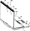
图1是本发明具有支撑机构的电子装置的第一实施例的立体图,说明支撑件在收合位置;FIG. 1 is a perspective view of the first embodiment of the electronic device with a supporting mechanism of the present invention, illustrating that the supporting member is in a retracted position;
图2是本发明具有支撑机构的电子装置的第一实施例的立体分解图;FIG. 2 is a three-dimensional exploded view of the first embodiment of the electronic device with a supporting mechanism of the present invention;
图3是本发明具有支撑机构的电子装置的第一实施例由另一视角观看的立体分解图;Fig. 3 is a three-dimensional exploded view of the first embodiment of the electronic device with a supporting mechanism viewed from another perspective;
图4是本发明具有支撑机构的电子装置的第一实施例的支撑机构的立体分解图;4 is an exploded perspective view of the support mechanism of the first embodiment of the electronic device with the support mechanism of the present invention;
图5是本发明具有支撑机构的电子装置的第一实施例的局部放大图;5 is a partially enlarged view of the first embodiment of the electronic device with a supporting mechanism of the present invention;
图6是本发明具有支撑机构的电子装置的第一实施例的局部放大图;6 is a partial enlarged view of the first embodiment of the electronic device with a supporting mechanism of the present invention;
图7是本发明具有支撑机构的电子装置的第一实施例的立体图;7 is a perspective view of the first embodiment of the electronic device with a supporting mechanism of the present invention;
图8是本发明具有支撑机构的电子装置的第一实施例的支撑机构的操作示意图;8 is a schematic diagram of the operation of the support mechanism of the first embodiment of the electronic device with the support mechanism of the present invention;
图9是本发明具有支撑机构的电子装置的第一实施例的立体图,说明支撑件在展开位置;FIG. 9 is a perspective view of the first embodiment of the electronic device with a supporting mechanism of the present invention, illustrating that the supporting member is in a deployed position;
图10是本发明具有支撑机构的电子装置的第一实施例的立体图,说明支撑件卡接于限位卡槽;FIG. 10 is a perspective view of the first embodiment of the electronic device with a supporting mechanism of the present invention, illustrating that the supporting member is engaged with the limiting slot;
图11是本发明具有支撑机构的电子装置的第二实施例的立体图,说明支撑件卡接于限位挡块;及FIG. 11 is a perspective view of the second embodiment of the electronic device with a supporting mechanism of the present invention, illustrating that the supporting member is engaged with the limit stopper; and
图12是本发明具有支撑机构的电子装置的第三实施例的立体图,说明支撑件抵接于粗糙面上。FIG. 12 is a perspective view of a third embodiment of the electronic device with a supporting mechanism of the present invention, illustrating that the supporting member abuts against a rough surface.
〔本发明〕〔this invention〕
100电子装置100 electronic devices
1基座1 base
11顶壁11 top wall
12、12’限位部12, 12' limit part
13粗糙面13 rough surface
2显示屏幕2 display screens
21容置槽21 storage slots
22贯孔22 through holes
23连接片23 connecting piece
231凹槽231 grooves
3支撑机构3 support mechanism
31接合板31 joint plate
311板体311 plate body
312螺柱312 stud
313第一铰接件313 first hinge
314弹性扣臂314 elastic buckle arm
315卡扣部315 buckle part
316斜边316 hypotenuse
32枢转板32 pivot plate
321板体321 plate body
322穿孔322 perforations
323凸伸臂323 convex outrigger
324通孔324 through holes
325第二铰接件325 second hinge
326轴部326 shaft
327挡止部327 stopper
33支撑件33 supports
331本体331 body
332枢接部332 pivot joint
333枢接孔333 pivot hole
334扳动部334 Pulling Department
335卡块335 blocks
34螺丝34 screws
4遮片4 mattes
41片体41 pieces
42连接柱42 connection column
421挡止部421 stopper
I、II箭头I, II arrows
III、IV箭头III, IV arrows
V箭头V arrow
具体实施方式 Detailed ways
有关本发明的前述及其它技术内容、特点与功效,在以下配合参考附图的三个实施例的详细说明中,将可清楚的呈现。通过具体实施方式的说明,当可对本发明为达成预定目的所采取的技术手段及功效得以更加深入且具体的了解,然而所附附图只是提供参考与说明之用,并非用来对本发明加以限制。The aforementioned and other technical contents, features and effects of the present invention will be clearly presented in the following detailed description of three embodiments with reference to the accompanying drawings. Through the description of the specific implementation, the technical means and effects of the present invention to achieve the intended purpose can be understood more deeply and specifically. However, the attached drawings are only for reference and description, and are not used to limit the present invention. .
在本发明被详细描述之前,要注意的是,在以下的说明内容中,类似的组件是以相同的编号来表示。Before the present invention is described in detail, it should be noted that in the following description, similar components are denoted by the same numerals.
如图1所示,是本发明具有支撑机构的电子装置的第一实施例,该电子装置100是以一笔记型计算机为例作说明,其包括一基座1、一可转动地枢接于基座1一端的显示屏幕2,及一支撑机构3。As shown in Figure 1, it is the first embodiment of the electronic device with supporting mechanism of the present invention. The
如图2、图3及图4所示,显示屏幕2背面形成有一容置槽21,用以供支撑机构3容置,支撑机构3包含一接合板31、两个枢转板32,及两个支撑件33。接合板31包括一板体311,及两个凸设于板体311前侧面的螺柱312,接合板31的两个螺柱312与显示屏幕2的两个与容置槽21相连通的贯孔22位置相对应,通过一螺丝34穿设于各贯孔22并螺锁于与贯孔22相对应的螺柱312,使得接合板31能锁固在显示屏幕2上。当然,接合板31的接合固定方式并不以本实施例所揭露的为限,接合板31也可通过卡合的方式卡固在显示屏幕2上。As shown in Fig. 2, Fig. 3 and Fig. 4, an
接合板31还包括两个凸设于板体311前侧面且左右相间隔的第一铰接件313,各第一铰接件313间隔位于各螺柱312外侧,用以供各枢转板32枢接,由此,使得各枢转板32可绕第一铰接件313相对于接合板31枢转。在本实施例中,各枢转板32包括一板体321,板体321形成有一沿前后方向延伸的穿孔322,各第一铰接件313包含多个呈环状排列且彼此相间隔的弹性扣臂314,各弹性扣臂314沿前后方向延伸,第一铰接件313的弹性扣臂314穿设于穿孔322时会被挤压而内缩,当弹性扣臂314的一位于末端的卡扣部315穿出穿孔322时,弹性扣臂314因复位弹力复位使得卡扣部315卡扣于板体321前端面,由此,在组装过程中,各枢转板32可迅速且方便地组装于各第一铰接件313上。The connecting
各枢转板32还包括两个凸设于板体321上的凸伸臂323,两个凸伸臂323彼此上下相间隔,支撑件33包括一本体331,本体331的一端凸设有一位于两个凸伸臂323之间的枢接部332,通过枢转板32的一第二铰接件325枢接于两个凸伸臂323与枢接部332,使得支撑件33可绕第二铰接件325相对于枢转板32枢转。Each pivoting
在本实施例中,支撑件33的枢接部332形成有一沿上下方向延伸的枢接孔333,各凸伸臂323形成有一沿上下方向延伸并与枢接孔333相连通的通孔324,第二铰接件325包含一穿设于枢接孔333与通孔324的轴部326,及两个凸设于轴部326且彼此上下相间隔的挡止部327,两个挡止部327分别抵接于两个凸伸臂323上下两外侧端,使得第二铰接件325的轴部326能稳固地保持在穿设于枢接孔333与通孔324的位置,而不会脱离枢接孔333与通孔324。再者,由于本实例的第一铰接件313的延伸方向与第二铰接件325的延伸方向相互垂直,因此,通过枢转板32可绕第一铰接件313相对于接合板31枢转,以及支撑件33可绕第二铰接件325相对于枢转板32枢转,使得支撑件33可同时绕两个相互垂直的轴向枢转,且支撑件33可在一容置于容置槽21内的收合位置(如图1所示),及一脱离容置槽21的展开位置(如图9所示)之间转动。In this embodiment, the
由于各枢转板32及各支撑件33是接合在接合板31的板体311前侧面,因此,为了防止支撑件33绕第二铰接件325枢转的过程中撞击到接合板31的板体311,板体311的左右两端分别形成有一斜边316,斜边316是由上朝下并朝内倾斜延伸,由此,可在各斜边316下方形成一空间供支撑件33通过,以防止支撑件33撞击到接合板31的板体311。另一方面,电子装置100还包括一遮片4,遮片4包含一片体41,及一凸设于片体41前侧的连接柱42,通过连接柱42卡接于显示屏幕2背面的一连接片23所形成的一凹槽231内,使得片体41能保持在遮蔽住部分外露的容置槽21的位置,由此,能防止灰尘累积在容置槽21内。Since each
如图5、图6及图7所示,当电子装置100在如图1所示的使用模式时,可通过下述操作方式将各支撑件33由收合位置转动到展开位置。首先,沿箭头I方向将遮片4的片体41往后拉,当连接柱42末端的一挡止部421抵接于连接片23时,片体41即无法被继续拉动,此时,即可沿箭头II或箭头II反向旋转片体41至一如图7所示朝向下方的位置。As shown in FIG. 5 , FIG. 6 and FIG. 7 , when the
如图7、图8及图9所示,扳动各支撑件33的一相反于枢接部332一端的扳动部334,使两支撑件33分别沿箭头III、IV方向绕第二铰接件325相对于枢转板32枢转,同时,两枢转板32带动两支撑件33分别沿箭头II、V方向绕第一铰接件313相对于接合板31旋转,以将各支撑件33由收合位置(如图7所示)转动到展开位置(如图9所示)。需说明的是,图9只是显示支撑件33转动到其中一个展开位置的状态。As shown in Fig. 7, Fig. 8 and Fig. 9, a pulling
如图9所示,在本实施例中,各支撑件33的一相反于枢接部332(如图8)的一端可抵接于基座1,以将显示屏幕2支撑于基座1上。较佳地,基座1包含一顶壁11,及多个设置于顶壁11上且彼此相间隔的限位部12,各支撑件33可与所述限位部12中一选择的限位部12卡接,由此,可将显示屏幕2稳固地支撑在基座1上并定位在一倾斜的角度位置。其中,各限位部12为一限位卡槽,各支撑件33包括一凸设于本体331相反于枢接部332一端的卡块335,卡块335可卡接于该限位卡槽内。需说明的是,显示屏幕2与基座1的顶壁11所夹的角度取决于支撑件33的长度以及限位部12设置的位置,可视需求变更限位部12的数量或者是支撑件33的长度。As shown in FIG. 9 , in this embodiment, one end of each supporting
如图9及图10所示,当使用者将电子装置100的显示屏幕2由图9所示的位置旋转到图10所示的位置时,通过位于展开位置的各支撑件33的本体331抵接于顶壁11,且卡块335卡接于一选择的限位部12内,使得显示屏幕2能稳固地定位在一倾斜角度位置而不会相对于基座1转动。此外,当使用者欲调整显示屏幕2的倾斜角度时,将显示屏幕2向上旋转使各支撑件33的卡块335脱离限位部12,接着,旋转各支撑件33使其卡块335对应到另一目标位置的限位部12,再将显示屏幕2向下旋转使各支撑件33的卡块335卡接于目标位置的限位部12后,即可达到调整显示屏幕2倾斜角度的功效。As shown in FIGS. 9 and 10, when the user rotates the
需说明的是,在设计时,第一铰接件313、枢转板32及支撑件33的数量也可各为一个,并不以本实施例所揭露的数量为限。It should be noted that, when designing, the number of the
如图11所示,是本发明具有支撑机构的电子装置的第二实施例,该电子装置100的整体结构与操作方式大致与第一实施例相同,但各限位部12’的设计略有不同。As shown in FIG. 11, it is the second embodiment of the electronic device with supporting mechanism of the present invention. The overall structure and operation mode of the
在本实施例中,各限位部12’为一呈L形且凸设于顶壁11上的限位挡块,各支撑件33的本体331抵接于顶壁11并卡接于一选择的限位部12’,由此,能将显示屏幕2稳固地定位在倾斜角度位置。In this embodiment, each limiting
如图12所示,是本发明具有支撑机构的电子装置的第三实施例,该电子装置100的整体结构与操作方式大致与第一实施例相同,但各支撑件33的定位方式设计有所不同。As shown in Figure 12, it is the third embodiment of the electronic device with supporting mechanism of the present invention. The overall structure and operation mode of the
在本实施例中,基座1包含两个形成于顶壁11且相间隔的粗糙面13,各支撑件33的本体331抵接于各粗糙面13上,通过本体331与粗糙面13之间相互干涉所产生的摩擦力作用,使得各支撑件33能将显示屏幕2稳固地定位在倾斜角度位置。In this embodiment, the
归纳上述,各实施例的电子装置100,通过枢转板32可绕第一铰接件313相对于接合板31枢转,以及支撑件33可绕第二铰接件325相对于枢转板32枢转,能将各支撑件33调整到卡接在限位部12、12’上,或者是与粗糙面13干涉抵接,使得显示屏幕2能稳固地定位在一倾斜角度位置,并且可选择地调整显示屏幕2的倾斜角度,故确实能达成本发明所诉求的目的。To sum up the above, the
惟以上所述者,仅为本发明的实施例,当不能以此限定本发明实施的范围,即大凡依本发明权利要求及发明说明内容所作的简单的等效变化与修饰,皆仍属本发明专利涵盖的范围内。But above-mentioned person is only the embodiment of the present invention, when can not limit the range of the present invention implementation with this, promptly all the simple equivalent changes and modifications done according to the claims of the present invention and content of the description of the invention, all still belong to this invention. within the scope of invention patents.
Claims (18)
Applications Claiming Priority (2)
| Application Number | Priority Date | Filing Date | Title |
|---|---|---|---|
| TW099144497A TWI409022B (en) | 2010-12-17 | 2010-12-17 | Supporting mechanism and an electronic device having the same |
| TW099144497 | 2010-12-17 |
Publications (1)
| Publication Number | Publication Date |
|---|---|
| CN102573360A true CN102573360A (en) | 2012-07-11 |
Family
ID=46234137
Family Applications (1)
| Application Number | Title | Priority Date | Filing Date |
|---|---|---|---|
| CN2010106053748A Pending CN102573360A (en) | 2010-12-17 | 2010-12-24 | Supporting mechanism and electronic device with same |
Country Status (3)
| Country | Link |
|---|---|
| US (1) | US20120155032A1 (en) |
| CN (1) | CN102573360A (en) |
| TW (1) | TWI409022B (en) |
Cited By (2)
| Publication number | Priority date | Publication date | Assignee | Title |
|---|---|---|---|---|
| CN114690918A (en) * | 2022-03-16 | 2022-07-01 | 苏州三星电子电脑有限公司 | Touch pad unit and electronic device with same |
| CN115551242A (en) * | 2021-06-30 | 2022-12-30 | 宸美(厦门)光电有限公司 | Folding electronic device |
Families Citing this family (3)
| Publication number | Priority date | Publication date | Assignee | Title |
|---|---|---|---|---|
| CN104358984B (en) * | 2014-09-30 | 2016-06-01 | 国网山东省电力公司邹城市供电公司 | A shelf structure of a kind of light relay producing apparatus |
| WO2022104642A1 (en) | 2020-11-19 | 2022-05-27 | 京东方科技集团股份有限公司 | Electronic device and rotating shaft mechanism therefor |
| US12585126B2 (en) | 2020-11-19 | 2026-03-24 | Beijing Boe Optoelectronics Technology Co., Ltd. | Electronic device and rotating shaft mechanism thereof |
Citations (3)
| Publication number | Priority date | Publication date | Assignee | Title |
|---|---|---|---|---|
| US6028768A (en) * | 1997-07-30 | 2000-02-22 | International Business Machines Corporation | Mechanism for deploying a keyboard for a portable computer |
| CN1536885A (en) * | 2003-04-07 | 2004-10-13 | 明基电通股份有限公司 | Display and foot stand for supporting display |
| CN1598968A (en) * | 2003-09-18 | 2005-03-23 | 三星电子株式会社 | Wall mount for display apparatus |
Family Cites Families (5)
| Publication number | Priority date | Publication date | Assignee | Title |
|---|---|---|---|---|
| TW524262U (en) * | 2001-08-16 | 2003-03-11 | Wen-Chi Lin | Positioning hinge |
| US7306190B2 (en) * | 2004-12-10 | 2007-12-11 | Illinois Tool Works Inc | Fastener |
| US7413152B1 (en) * | 2007-02-06 | 2008-08-19 | Kernan Technology Co., Ltd. | Carrier device for monitor |
| US7925310B2 (en) * | 2007-06-05 | 2011-04-12 | Accton Technology Corporation | Communication device with stickup structure |
| TW200850110A (en) * | 2007-06-05 | 2008-12-16 | Accton Technology Corp | Communication device with stickup structure |
-
2010
- 2010-12-17 TW TW099144497A patent/TWI409022B/en not_active IP Right Cessation
- 2010-12-24 CN CN2010106053748A patent/CN102573360A/en active Pending
-
2011
- 2011-06-22 US US13/166,449 patent/US20120155032A1/en not_active Abandoned
Patent Citations (3)
| Publication number | Priority date | Publication date | Assignee | Title |
|---|---|---|---|---|
| US6028768A (en) * | 1997-07-30 | 2000-02-22 | International Business Machines Corporation | Mechanism for deploying a keyboard for a portable computer |
| CN1536885A (en) * | 2003-04-07 | 2004-10-13 | 明基电通股份有限公司 | Display and foot stand for supporting display |
| CN1598968A (en) * | 2003-09-18 | 2005-03-23 | 三星电子株式会社 | Wall mount for display apparatus |
Cited By (3)
| Publication number | Priority date | Publication date | Assignee | Title |
|---|---|---|---|---|
| CN115551242A (en) * | 2021-06-30 | 2022-12-30 | 宸美(厦门)光电有限公司 | Folding electronic device |
| CN115551242B (en) * | 2021-06-30 | 2025-09-05 | 宸美(厦门)光电有限公司 | Folding electronic device |
| CN114690918A (en) * | 2022-03-16 | 2022-07-01 | 苏州三星电子电脑有限公司 | Touch pad unit and electronic device with same |
Also Published As
| Publication number | Publication date |
|---|---|
| US20120155032A1 (en) | 2012-06-21 |
| TW201228547A (en) | 2012-07-01 |
| TWI409022B (en) | 2013-09-11 |
Similar Documents
| Publication | Publication Date | Title |
|---|---|---|
| CN104344184B (en) | Portable and collapsible support | |
| US8936229B2 (en) | Housing assembly and electronic device using the same | |
| CN105874400B (en) | Stand for portable computing device | |
| CN209325304U (en) | Supporting component and electronic device using same | |
| US11054866B2 (en) | Hinge module and electronic device | |
| US8339777B2 (en) | Portable electronic device with improved pivoting range | |
| CN103174736B (en) | Double-shaft type pivoting mechanism and electronic device thereof | |
| CN105103077A (en) | Dual-part hinge assembly | |
| TWI505069B (en) | Electronic device | |
| CN102573360A (en) | Supporting mechanism and electronic device with same | |
| JP2006099764A (en) | Portable computer system | |
| CN102707769A (en) | Docking stations and electronic equipment using docking stations, portable electronic devices | |
| TWM539645U (en) | Hinge for electronic devices | |
| KR101955932B1 (en) | Notebook with a removable pad-typed mouse | |
| CN103838306B (en) | Electronic device | |
| TWI457748B (en) | External inputting device and related detachable computer system | |
| TW201448715A (en) | Electronic device | |
| CN105759898B (en) | Electronic product and electronic equipment | |
| CN110275571A (en) | Portable Electronic Device | |
| CN215636123U (en) | Flat plate support | |
| CN201820167U (en) | Tablet e-reader stand leather case with swivel cover | |
| JP6060753B2 (en) | Electronic equipment | |
| JP2005293178A (en) | Note pc support and note pc support device | |
| TWM468873U (en) | Portable electronic device and support module thereof | |
| CN107577276B (en) | Input device with support structure |
Legal Events
| Date | Code | Title | Description |
|---|---|---|---|
| C06 | Publication | ||
| PB01 | Publication | ||
| C10 | Entry into substantive examination | ||
| SE01 | Entry into force of request for substantive examination | ||
| C02 | Deemed withdrawal of patent application after publication (patent law 2001) | ||
| WD01 | Invention patent application deemed withdrawn after publication |
Application publication date: 20120711 |