CN102520630B - Automatic power and amplitude modulation factor control circuit and power adjustment method - Google Patents
Automatic power and amplitude modulation factor control circuit and power adjustment method Download PDFInfo
- Publication number
- CN102520630B CN102520630B CN201110399066.9A CN201110399066A CN102520630B CN 102520630 B CN102520630 B CN 102520630B CN 201110399066 A CN201110399066 A CN 201110399066A CN 102520630 B CN102520630 B CN 102520630B
- Authority
- CN
- China
- Prior art keywords
- circuit
- power
- signal
- sine wave
- input end
- Prior art date
- Legal status (The legal status is an assumption and is not a legal conclusion. Google has not performed a legal analysis and makes no representation as to the accuracy of the status listed.)
- Active
Links
Images


Landscapes
- Amplifiers (AREA)
Abstract
Description
技术领域 technical field
本发明主要涉及一种功率调整领域,尤其是涉及一种功率及调幅度自动控制电路和功率调整方法。The invention mainly relates to the field of power adjustment, in particular to an automatic control circuit for power and amplitude modulation and a power adjustment method.
背景技术 Background technique
在中波发射机中,输出功率与脉宽调制板上所产生的正弦波的直流电平的平方成正比,调幅度与正弦波的直流电平以及幅度成函数关系。在原先的中波发射机中,技术人员通过观察机器上的功率计表头的读数后,人为地调整电位器,从而实现功率调整,类似地,技术人员通过使用专业的检测仪器观察调幅度后,人为地调整电位器,从而实现调幅度调整。这种调整方式需要技术人员进行准确测量或者计算后进行调整,非技术人员无法进行操作。In a medium wave transmitter, the output power is proportional to the square of the DC level of the sine wave generated on the PWM board, and the modulation amplitude is a function of the DC level and amplitude of the sine wave. In the original medium-wave transmitter, technicians manually adjust the potentiometer after observing the readings of the power meter on the machine, so as to realize power adjustment. , Artificially adjust the potentiometer, so as to realize the adjustment of the amplitude. This adjustment method requires technical personnel to perform accurate measurement or adjustment after calculation, and non-technical personnel cannot operate.
发明内容 Contents of the invention
本发明解决的技术问题是,提供一种功率及调幅度自动控制电路和功率调整方法,能够解决现有技术中需要人工调整功率和幅度的技术问题。The technical problem solved by the present invention is to provide an automatic power and amplitude modulation control circuit and a power adjustment method, which can solve the technical problem in the prior art that manual adjustment of power and amplitude is required.
为解决上述技术问题,本发明提供一种功率调制设备,包括单片机、正弦波产生电路、模数转换电路、调整电路、三角波产生电路、脉宽调制电路以及放大电路;所述模数转换电路的输入端与外置功放电路的输出端相连接,所述模数转换电路的输出端与所述单片机的输入端相连接,所述单片机的输出端与所述调整电路的输入端相连接,所述调整电路的输出端与所述脉宽调制电路的输入端相连接,所述脉宽调制电路的输出端与所述放大电路的输入端相连接,所述脉宽调制电路的输出端与外置功放电路的输入端相连接;所述单片机的输出端还与所述正弦波产生电路的输入端相连接;所述正弦波产生电路的输出端与所述调整电路的输入端相连接;所述模数转换电路用于对来自功放电路的功率取样信号进行模数转换,并将转换后的信号输出到单片机;所述单片机用于接收来自所述模数转换电路的信号,并与内置的功率基准值相比对,根据比对结果,控制调整电路和正弦波产生电路;所述调整电路用于接收来自正弦波产生电路的正弦波信号,并根据来自单片机的控制信号,控制所述正弦波信号的输出幅度;所述脉宽调制形成电路用于接收来自调整电路的正弦波信号,并接收来自三角波产生电路的副载波信号,并对所述正弦波信号进行脉宽调制;所述放大电路用于放大接收到的信号并输出到外置的功放电路。In order to solve the above-mentioned technical problems, the present invention provides a power modulation device, including a single-chip microcomputer, a sine wave generating circuit, an analog-to-digital conversion circuit, an adjustment circuit, a triangular wave generating circuit, a pulse width modulation circuit and an amplifying circuit; the analog-to-digital conversion circuit The input end is connected with the output end of the external power amplifier circuit, the output end of the analog-to-digital conversion circuit is connected with the input end of the single-chip microcomputer, and the output end of the single-chip microcomputer is connected with the input end of the adjustment circuit, so The output end of the adjustment circuit is connected to the input end of the pulse width modulation circuit, the output end of the pulse width modulation circuit is connected to the input end of the amplification circuit, and the output end of the pulse width modulation circuit is connected to the external The input end of the power amplifier circuit is connected; the output end of the single-chip microcomputer is also connected with the input end of the sine wave generation circuit; the output end of the sine wave generation circuit is connected with the input end of the adjustment circuit; the The analog-to-digital conversion circuit is used to perform analog-to-digital conversion on the power sampling signal from the power amplifier circuit, and outputs the converted signal to the single-chip microcomputer; the single-chip microcomputer is used to receive the signal from the analog-to-digital conversion circuit, and with the built-in The power reference value is compared, and according to the comparison result, the control adjustment circuit and the sine wave generation circuit; the adjustment circuit is used to receive the sine wave signal from the sine wave generation circuit, and control the sine wave according to the control signal from the single chip microcomputer. The output amplitude of the wave signal; the pulse width modulation forming circuit is used to receive the sine wave signal from the adjustment circuit, and receive the subcarrier signal from the triangular wave generation circuit, and perform pulse width modulation on the sine wave signal; the amplifying The circuit is used to amplify the received signal and output it to an external power amplifier circuit.
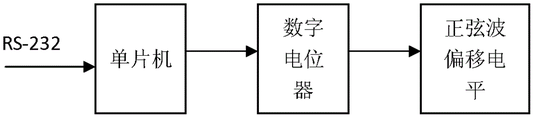
其中,所述调整电路包括第一数字电位器、调整正弦波幅度电路,第二数字电位器、调整正弦波直流偏移电平电路,所述第一数字电位器的输入端、第二数字电位器的输入端均与所述单片机的输出端相连接,所述第一数字电位器的输入端、第二数字电位器的输入端还与所述正弦波产生电路的输出端相连接;所述第一数字电位器的输出端、第二数字电位器的输出端均与所述脉宽调制形成电路的输入端相连接。Wherein, the adjustment circuit includes a first digital potentiometer, a circuit for adjusting the amplitude of the sine wave, a second digital potentiometer, a circuit for adjusting the DC offset level of the sine wave, the input terminal of the first digital potentiometer, the second digital potentiometer The input terminals of the devices are all connected with the output terminals of the single-chip microcomputer, and the input terminals of the first digital potentiometer and the second digital potentiometer are also connected with the output terminals of the sine wave generating circuit; The output end of the first digital potentiometer and the output end of the second digital potentiometer are both connected to the input end of the pulse width modulation forming circuit.
其中,所述第一数字电位器的通过调整阻值的变化,调整输出的正弦波信号的幅度。Wherein, the amplitude of the output sine wave signal is adjusted by adjusting the resistance value of the first digital potentiometer.
其中,所述第二数字电位器通过调整阻值的变化,调整输出的正弦波信号的偏移电平。Wherein, the second digital potentiometer adjusts the offset level of the output sine wave signal by adjusting the change of the resistance value.
其中,所述脉宽调制形成电路包括自动功率及调幅度自动控制电路和高速比较器,所述自动功率及调幅度自动控制电路与所述高速比较器相连接,用以提供可调节的直流电平,所述直流电平与音频放大信号进行叠加后输出到高速比较器的反相输入端;所述高速比较器的正向输入端接收来自三角波产生电路的副载波信号;所述高速比较器的输出端与所述放大电路相连接,用于向所述放大电路输出脉冲信号。Wherein, the pulse width modulation forming circuit includes an automatic power and amplitude modulation automatic control circuit and a high-speed comparator, and the automatic power and amplitude modulation automatic control circuit is connected with the high-speed comparator to provide an adjustable DC level , the DC level and the audio amplification signal are superimposed and output to the inverting input of the high-speed comparator; the positive input of the high-speed comparator receives the subcarrier signal from the triangular wave generation circuit; the output of the high-speed comparator The terminal is connected with the amplifying circuit, and is used for outputting a pulse signal to the amplifying circuit.
为解决上述技术问题,本发明还提供一种功率调整方法,包括以下步骤:In order to solve the above technical problems, the present invention also provides a power adjustment method, including the following steps:
步骤1:对输出信号进行AD采样,计算采样信号的功率、调幅度;Step 1: Carry out AD sampling on the output signal, and calculate the power and amplitude modulation of the sampling signal;
步骤2:将所述信号的功率、调幅度与内置的预置值相比较,判断是否在误差范围内,若是,则返回步骤1;若否,则转到步骤3;Step 2: Compare the power and amplitude of the signal with the built-in preset value to judge whether it is within the error range, if yes, return to step 1; if not, go to step 3;
步骤3:计算当前实际功率及调幅度对应的正弦波的直流电平和幅度值;Step 3: Calculate the DC level and amplitude value of the sine wave corresponding to the current actual power and modulation amplitude;
步骤4:计算差值对应的正弦波直流电平及调幅值;Step 4: Calculate the sine wave DC level and amplitude modulation value corresponding to the difference;
步骤5:改变数字电位器的电阻值,从而改变相应的正弦波直流电平及幅度值,返回步骤1。Step 5: Change the resistance value of the digital potentiometer, thereby changing the corresponding sine wave DC level and amplitude value, and return to step 1.
其中,所述AD采样时间为每隔2s读取一次采样信号。Wherein, the AD sampling time is to read a sampling signal every 2s.
采用上述技术方案,对比现有技术中的需要不能自动调整功率和幅度的技术问题,本发明的有益效果是:由于在单片机中设置了标准的功率和调幅度值,通过对输出信号进行采样,将采样信号与调幅度值相对比,将对比结果作为调整输出功率的基准,单片机控制正弦波产生电路以及数字电位器,通过数字电位器阻值的调整,控制输出的正弦波的功率和调幅度,从而实现自动的功率调整,克服了人工调整效率低的问题。Adopting the above-mentioned technical scheme, compared with the technical problem in the prior art that the power and amplitude cannot be automatically adjusted, the beneficial effect of the present invention is: since the standard power and amplitude modulation values are set in the single-chip microcomputer, by sampling the output signal, Compare the sampling signal with the amplitude modulation value, and use the comparison result as a benchmark for adjusting the output power. The single-chip microcomputer controls the sine wave generation circuit and the digital potentiometer, and controls the output sine wave power and modulation amplitude through the adjustment of the resistance value of the digital potentiometer. , so as to realize automatic power adjustment and overcome the problem of low efficiency of manual adjustment.
附图说明 Description of drawings
图1为本发明提供的功率及调幅度自动控制电路的结构图;Fig. 1 is the structural diagram of power and amplitude modulation automatic control circuit provided by the present invention;
图2为本发明提供的功率及调幅度自动控制电路的一种实施例的具体结构图;Fig. 2 is the specific structural diagram of a kind of embodiment of the power and amplitude modulation automatic control circuit provided by the present invention;
图3为本发明提供的功率调整方法的流程图;Fig. 3 is a flowchart of the power adjustment method provided by the present invention;
图4为本发明提供的正弦波DC电平、幅度与调幅度的关系图;Fig. 4 is the relationship diagram of sine wave DC level, amplitude and modulation amplitude provided by the present invention;
图5为本发明提供的输出功率自动调整原理图;Fig. 5 is a schematic diagram of the automatic adjustment of output power provided by the present invention;
图6为本发明提供的调制度自动调整原理图;Fig. 6 is a schematic diagram of the automatic adjustment of the modulation degree provided by the present invention;
图7为本发明提供的脉宽调制形成电路的原理图;7 is a schematic diagram of a pulse width modulation forming circuit provided by the present invention;
图8为本发明提供的脉宽调制电路的原理款图。FIG. 8 is a schematic diagram of the pulse width modulation circuit provided by the present invention.
具体实施方式 Detailed ways
为详细说明本发明的技术内容、构造特征、所实现目的及效果,以下结合实施方式并配合附图详予说明。In order to describe the technical content, structural features, achieved goals and effects of the present invention in detail, the following will be described in detail in conjunction with the embodiments and accompanying drawings.
请参阅图1,本发明提供一种功率及调幅度自动控制电路,包括单片机、正弦波产生电路、模数转换电路、调整电路、三角波产生电路、脉宽调制电路、放大电路;所述模数转换电路的输入端与外置功放电路的输出端相连接,所述模数转换电路的输出端与所述单片机的输入端相连接,所述单片机的输出端与所述调整电路的输入端相连接,所述调整电路的输出端与所述脉宽调制电路的输入端相连接,所述脉宽调制电路的输出端与所述放大电路的输入端相连接,所述脉宽调制电路的输出端与外置功放电路的输入端相连接;所述单片机的输出端还与所述正弦波产生电路的输入端相连接;所述正弦波产生电路的输出端与所述调整电路的输入端相连接;所述模数转换电路用于对来自功放电路的功率取样信号进行模数转换,并将转换后的信号输出单片机;所述单片机用于接收来自所述模数转换电路的信号,并与内置的功率基准值相比对,根据比对结果,控制调整电路和正弦波产生电路;所述调整电路用于接收来自正弦波产生电路的正弦波信号,并根据来自单片机的控制信号,控制所述正弦波信号的输出幅度;所述脉宽调制形成电路用于接收来自调整电路的正弦波信号,并接收来自三角波产生电路的副载波信号,并所述正弦波信号进行脉宽调制;所述放大电路用于放大接收到的信号并输出到外置的功放电路。Please refer to Fig. 1, the present invention provides a kind of power and amplitude modulation automatic control circuit, comprise single-chip microcomputer, sine wave generation circuit, analog-to-digital conversion circuit, adjustment circuit, triangular wave generation circuit, pulse width modulation circuit, amplifying circuit; The input end of the conversion circuit is connected to the output end of the external power amplifier circuit, the output end of the analog-to-digital conversion circuit is connected to the input end of the single-chip microcomputer, and the output end of the single-chip microcomputer is connected to the input end of the adjustment circuit. connected, the output terminal of the adjustment circuit is connected with the input terminal of the pulse width modulation circuit, the output terminal of the pulse width modulation circuit is connected with the input terminal of the amplification circuit, and the output terminal of the pulse width modulation circuit end is connected with the input end of the external power amplifier circuit; the output end of the single-chip microcomputer is also connected with the input end of the sine wave generation circuit; the output end of the sine wave generation circuit is connected with the input end of the adjustment circuit connected; the analog-to-digital conversion circuit is used to carry out analog-to-digital conversion to the power sampling signal from the power amplifier circuit, and outputs the converted signal to the single-chip microcomputer; the single-chip microcomputer is used to receive the signal from the analog-to-digital conversion circuit, and communicate with The built-in power reference value is compared, and the adjustment circuit and the sine wave generation circuit are controlled according to the comparison result; the adjustment circuit is used to receive the sine wave signal from the sine wave generation circuit, and control the The output amplitude of the sine wave signal; the pulse width modulation forming circuit is used to receive the sine wave signal from the adjustment circuit, and receive the subcarrier signal from the triangular wave generation circuit, and perform pulse width modulation on the sine wave signal; The amplifier circuit is used to amplify the received signal and output it to an external power amplifier circuit.
请参阅图2,所述调整电路包括第一数字电位器、调整正弦波幅度电路,第二数字电位器、调整正弦波直流偏移电平电路,所述第一数字电位器的输入端、第二数字电位器的输入端均与所述单片机的输出端相连接,所述第一数字电位器的输入端、第二数字电位器的输入端还与所述正弦波产生电路的输出端相连接;所述第一数字电位器的输出端、第二数字电位器的输出端均与所述脉宽调制形成电路的输入端相连接。Please refer to Figure 2, the adjustment circuit includes a first digital potentiometer, a circuit for adjusting the amplitude of the sine wave, a second digital potentiometer, a circuit for adjusting the DC offset level of the sine wave, the input terminal of the first digital potentiometer, the second The input terminals of the two digital potentiometers are all connected with the output terminals of the single-chip microcomputer, and the input terminals of the first digital potentiometer and the second digital potentiometer are also connected with the output terminals of the sine wave generating circuit ; The output end of the first digital potentiometer and the output end of the second digital potentiometer are both connected to the input end of the pulse width modulation forming circuit.
在本实施例中,所述第一数字电位器的通过调整阻值的变化,调整输出的正弦波信号的幅度。所述第二数字电位器通过调整阻值的变化,调整输出的正弦波信号的偏移电平。In this embodiment, the amplitude of the output sine wave signal is adjusted by adjusting the resistance value of the first digital potentiometer. The second digital potentiometer adjusts the offset level of the output sine wave signal by adjusting the change of the resistance value.
进一步的,所述脉宽调制形成电路包括自动功率及调幅度自动控制电路和高速比较器,所述自动功率及调幅度自动控制电路与所述高速比较器相连接,用以提供可调节的直流电平,所述直流电平与音频放大信号进行叠加后输出到高速比较器的反相输入端;所述高速比较器的正向输入端接收来自三角波产生电路的副载波信号;所述高速比较器的输出端与所述放大电路相连接,用于向所述放大电路输出脉冲信号。Further, the pulse width modulation forming circuit includes an automatic power and amplitude modulation automatic control circuit and a high-speed comparator, and the automatic power and amplitude modulation automatic control circuit is connected with the high-speed comparator to provide adjustable direct current flat, the DC level and the audio amplification signal are superimposed and output to the inverting input of the high-speed comparator; the positive input of the high-speed comparator receives the subcarrier signal from the triangular wave generation circuit; the high-speed comparator The output end is connected with the amplifying circuit, and is used for outputting a pulse signal to the amplifying circuit.
在本实施例中,所述正弦波产生电路的工作方式是:单片机每隔61.5us读取一次存储器存储的正弦波采样值,这个采样值进行D/A转换(数模转换),产生相应的梯形波形,梯形波形再经过放大滤波后得到1020Hz的正弦波。In this embodiment, the working method of the sine wave generating circuit is: the single-chip microcomputer reads the sine wave sampling value stored in the memory every 61.5us, and the sampling value is subjected to D/A conversion (digital-to-analog conversion) to generate a corresponding Trapezoidal waveform, the trapezoidal waveform is amplified and filtered to obtain a 1020Hz sine wave.
三角波产生电路的工作方式是:在脉宽调制电路中需要一个副载波信号,为脉宽调制形成电路提供一个高频的三角波比较信号。三角波的产生需要一个滞回比较器和一个积分器。在采用单电源供电的情况下,常规的三角波振荡电路其闭环回路无法正常工作,而如图6能够产生幅度对称而且稳定的三角波。工作原理是:比较器输出的高低电平控制MOSFET开关的导通和关断,而在MOSFET开关导通和关断的情况下,由参考电平限制,积分器的电容分别以同样大小的电流充放电,于是积分器能够输出上升部分和下降部分斜率一致的三角波。三角波再作为滞回比较器的输入,使之产生高低电平控制MOSFET开关的导通和关断。The working mode of the triangular wave generation circuit is: a subcarrier signal is required in the pulse width modulation circuit, and a high frequency triangular wave comparison signal is provided for the pulse width modulation forming circuit. Triangular wave generation requires a hysteresis comparator and an integrator. In the case of a single power supply, the closed-loop circuit of the conventional triangular wave oscillation circuit cannot work normally, but as shown in Figure 6, it can generate a symmetrical and stable triangular wave. The working principle is: the high and low levels output by the comparator control the turn-on and turn-off of the MOSFET switch, and in the case of the turn-on and turn-off of the MOSFET switch, it is limited by the reference level, and the capacitors of the integrator are respectively charged with the same current Charge and discharge, so the integrator can output a triangular wave with the same slope of the rising part and the falling part. The triangular wave is then used as the input of the hysteresis comparator to generate high and low levels to control the turn-on and turn-off of the MOSFET switch.
单片机对采样的调幅度进行判断后,控制数字电位器,使其阻值发生相应的变化,从而控制正弦波的输出幅度,达到自动调整调制度的目的。After the single-chip microcomputer judges the modulation range of the sampling, it controls the digital potentiometer to make its resistance change accordingly, thereby controlling the output range of the sine wave and achieving the purpose of automatically adjusting the modulation degree.
其中,请参与图5和图6,调整正弦波幅度电路、调整正弦波直流偏移电平电路的工作方式是:通过一个MCU决策判断数据采集来的输出功率和调制度的检测值,送出调整信息,对SPWM电路进行实时调整,使驱动音频脉宽调制功放的脉宽调制信号能够实现闭环的自动调整,也就实现功率和调制度的自动调制。具体的,单片机先对输出功率进行采样,与功率基准值进行比较,根据比较结果,控制数字电位器,使其阻值进行相应的变化,让正弦波的偏移电平增大或减小,从而实现输出功率的自动调整。同理,单片机对采样的调幅度进行判断后,控制数字电位器,使其阻值发生相应的变化,从而控制正弦波的输出幅度,达到自动调整调制度的目的。Among them, please refer to Figure 5 and Figure 6. The working method of adjusting the sine wave amplitude circuit and adjusting the sine wave DC offset level circuit is: through an MCU decision to judge the output power and the detection value of the modulation degree from data collection, and send out the adjustment Information, adjust the SPWM circuit in real time, so that the pulse width modulation signal driving the audio pulse width modulation power amplifier can realize closed-loop automatic adjustment, which also realizes automatic modulation of power and modulation degree. Specifically, the single-chip microcomputer first samples the output power and compares it with the power reference value. According to the comparison result, the digital potentiometer is controlled to change its resistance accordingly, so that the offset level of the sine wave increases or decreases. In order to realize the automatic adjustment of the output power. In the same way, after the single-chip microcomputer judges the modulation amplitude of the sampling, it controls the digital potentiometer to make its resistance change accordingly, thereby controlling the output amplitude of the sine wave and achieving the purpose of automatically adjusting the modulation degree.
请参阅图7和图8,脉宽调制形成电路的工作原理是:脉宽调制就是利用音频正弦波对三角波进行调制,从而得到一个幅度相同、脉冲宽度变化的脉冲串。将正弦波与三角波送入比较器进行比较,这样从比较器的输出端就得到一个脉宽受调制的脉冲串。这个脉冲串的脉宽随着音频变化而变化,因而它带有音频信息。在本方案中是利用高速比较器LT1715来实现脉宽调制的。音频信号与一个可调的直流电平叠加后送到LT1715的反相输入端(3脚),副载波信号(100KHz)则送到LT1715的正相输入端,这样在LT1715的输出端就得到一个宽度随音频信号幅度变化而变化的TTL脉冲信号。通过调整自动功率及调幅度自动控制电路输出到比较器反相输入端的直流电平,可以调节音频信号的直流电平从而改变输出脉冲的宽度,最终实现了对载波功放输出功率的自动调整。Please refer to Figure 7 and Figure 8, the working principle of the pulse width modulation forming circuit is: pulse width modulation is to use the audio sine wave to modulate the triangular wave, so as to obtain a pulse train with the same amplitude and varying pulse width. The sine wave and triangular wave are sent to the comparator for comparison, so that a pulse train with modulated pulse width is obtained from the output terminal of the comparator. The pulse width of this pulse train varies with the audio frequency, so it carries audio information. In this scheme, high-speed comparator LT1715 is used to realize pulse width modulation. The audio signal is superimposed with an adjustable DC level and sent to the inverting input of LT1715 (pin 3), and the subcarrier signal (100KHz) is sent to the non-inverting input of LT1715, so that a width is obtained at the output of LT1715 A TTL pulse signal that varies with the amplitude of the audio signal. By adjusting the DC level of the automatic power and amplitude modulation automatic control circuit output to the inverting input of the comparator, the DC level of the audio signal can be adjusted to change the output pulse width, and finally the automatic adjustment of the output power of the carrier power amplifier is realized.
请参阅图3,本发明还提供一种功率调整方法,包括以下步骤:Referring to Fig. 3, the present invention also provides a power adjustment method, including the following steps:
步骤1:对输出信号进行AD采样,计算采样信号的功率、调幅度;Step 1: Carry out AD sampling on the output signal, and calculate the power and amplitude modulation of the sampling signal;
步骤2:将所述信号的功率、调幅度与内置的预置值相比较,判断是否在误差范围内,若是,则返回步骤1;若否,则转到步骤3;Step 2: Compare the power and amplitude of the signal with the built-in preset value to judge whether it is within the error range, if yes, return to step 1; if not, go to step 3;
步骤3:计算当前实际功率及调幅度对应的正弦波的直流电平和幅度值;Step 3: Calculate the DC level and amplitude value of the sine wave corresponding to the current actual power and modulation amplitude;
步骤4:计算差值对应的正弦波直流电平及调幅值;Step 4: Calculate the sine wave DC level and amplitude modulation value corresponding to the difference;
步骤5:改变数字电位器的电阻值,从而改变相应的正弦波直流电平及幅度值,返回步骤1。Step 5: Change the resistance value of the digital potentiometer, thereby changing the corresponding sine wave DC level and amplitude value, and return to step 1.
进一步的,步骤1中的所述AD采样时间为每隔2s读取一次采样信号。Further, the AD sampling time in step 1 is to read a sampling signal every 2s.
请参阅图4,本发明采用这种方法,其采用的基本计算原理是:Please refer to Fig. 4, the present invention adopts this method, and the basic calculation principle that it adopts is:
1)通过调节正弦波的DC电平控制输出的功率1) Control the output power by adjusting the DC level of the sine wave
2)通过调节正弦波的幅度控制调幅度2) Control the modulation amplitude by adjusting the amplitude of the sine wave
3)由于改变输出功率会改变调幅度,而改变调幅度不会改变输出功率,因此每次调整的时候先调整功率,再调整调幅度3) Because changing the output power will change the modulation range, but changing the modulation range will not change the output power, so adjust the power first, and then adjust the modulation range each time you adjust
4)正弦波的DC电平的平方与输出功率成正比4) The square of the DC level of the sine wave is proportional to the output power
三角波幅度范围是[0V,5V],因此任何与三角波比较的信号,它与三角波最低电平(也就是0V)的差值经调制功放后会以同等比例被放大(D类功放原理),而这个差值显然就是它的电平值。也就是说,假设电平值为1V的信号经调制功放后被放大为10V,那么电平值为2V的信号将被放大为40V,于是在负载不变的情况下,输出功率将为原来的22倍。The amplitude range of the triangular wave is [0V, 5V], so any signal compared with the triangular wave, the difference between it and the lowest level of the triangular wave (that is, 0V) will be amplified in the same proportion after being modulated by the power amplifier (class D power amplifier principle), and This difference is obviously its level value. That is to say, if a signal with a level value of 1V is amplified to 10V after being modulated by a power amplifier, then a signal with a level value of 2V will be amplified to 40V, so the output power will be the original 22 times.
5)调幅度与正弦波的DC电平和幅度有直接的关系:5) The modulation amplitude is directly related to the DC level and amplitude of the sine wave:
调幅度
调幅度
又由图4得:
以上所述仅为本发明的实施例,并非因此限制本发明的专利范围,凡是利用本发明说明书及附图内容所作的等效结构或等效流程变换,或直接或间接运用在其他相关的技术领域,均同理包括在本发明的专利保护范围内。The above is only an embodiment of the present invention, and does not limit the patent scope of the present invention. Any equivalent structure or equivalent process transformation made by using the description of the present invention and the contents of the accompanying drawings, or directly or indirectly used in other related technologies fields, all of which are equally included in the scope of patent protection of the present invention.
Claims (4)
Priority Applications (1)
| Application Number | Priority Date | Filing Date | Title |
|---|---|---|---|
| CN201110399066.9A CN102520630B (en) | 2011-12-05 | 2011-12-05 | Automatic power and amplitude modulation factor control circuit and power adjustment method |
Applications Claiming Priority (1)
| Application Number | Priority Date | Filing Date | Title |
|---|---|---|---|
| CN201110399066.9A CN102520630B (en) | 2011-12-05 | 2011-12-05 | Automatic power and amplitude modulation factor control circuit and power adjustment method |
Publications (2)
| Publication Number | Publication Date |
|---|---|
| CN102520630A CN102520630A (en) | 2012-06-27 |
| CN102520630B true CN102520630B (en) | 2014-04-16 |
Family
ID=46291583
Family Applications (1)
| Application Number | Title | Priority Date | Filing Date |
|---|---|---|---|
| CN201110399066.9A Active CN102520630B (en) | 2011-12-05 | 2011-12-05 | Automatic power and amplitude modulation factor control circuit and power adjustment method |
Country Status (1)
| Country | Link |
|---|---|
| CN (1) | CN102520630B (en) |
Families Citing this family (5)
| Publication number | Priority date | Publication date | Assignee | Title |
|---|---|---|---|---|
| CN105939179A (en) * | 2016-06-21 | 2016-09-14 | 新疆维吾尔自治区广播电影电视局节目传输中心 | System and method for monitoring input audio, broadcasting state and modulation amplitude of medium-wave transmitter |
| CN110808747A (en) * | 2019-11-26 | 2020-02-18 | 中兵通信科技股份有限公司 | An airborne transmitter power output and modulation degree detection circuit |
| CN111614330A (en) * | 2020-06-05 | 2020-09-01 | 恩平灵特电子科技有限公司 | An audio signal generator with continuously and greatly adjustable crest factor |
| CN111625047B (en) * | 2020-07-06 | 2021-08-27 | 安阳复星合力新材料股份有限公司 | Heating power control method for intermediate frequency power supply |
| CN115085515B (en) * | 2022-08-22 | 2022-11-22 | 成都动芯微电子有限公司 | Output power adjustable circuit |
Family Cites Families (5)
| Publication number | Priority date | Publication date | Assignee | Title |
|---|---|---|---|---|
| US6751448B1 (en) * | 1999-10-13 | 2004-06-15 | Intel Corporation | Control of transmission power in a communication system |
| US6686831B2 (en) * | 2001-01-23 | 2004-02-03 | Invensys Systems, Inc. | Variable power control for process control instruments |
| US7558539B2 (en) * | 2005-09-30 | 2009-07-07 | Freescale Semiconductor, Inc. | Power control feedback loop for adjusting a magnitude of an output signal |
| KR101242880B1 (en) * | 2008-02-08 | 2013-03-18 | 스카이워크스 솔루션즈 인코포레이티드 | Closed-loop adaptive power control for adjusting bandwidth in a mobile handset transmitter |
| CN102033500A (en) * | 2010-10-15 | 2011-04-27 | 北京联合大学生物化学工程学院 | Emitter follower circuit capable of automatically regulating quiescent operation point |
-
2011
- 2011-12-05 CN CN201110399066.9A patent/CN102520630B/en active Active
Also Published As
| Publication number | Publication date |
|---|---|
| CN102520630A (en) | 2012-06-27 |
Similar Documents
| Publication | Publication Date | Title |
|---|---|---|
| CN102520630B (en) | Automatic power and amplitude modulation factor control circuit and power adjustment method | |
| CN102109556B (en) | A MEMS device dynamic weak capacitance detection circuit | |
| CN103997206A (en) | Switching power source | |
| CN105048814A (en) | Flyback power supply and its control circuit and control method | |
| CN106877824A (en) | Envelope tracking power supply control system and method based on FPGA signal processing | |
| CN109581010B (en) | AC voltage standard source | |
| CN102116757A (en) | Electrical conductivity measurement system and method for liquid | |
| CN105302019A (en) | An electro-optic modulator bias operating point control device and method | |
| CN102620862A (en) | Temperature checker | |
| CN104535954A (en) | Calibration device of active leakage current tester | |
| CN102809684B (en) | Power detection method and power detection circuit of power supply primary side circuit | |
| CN204347229U (en) | The calibrating installation of active leakage current tester | |
| CN109492324B (en) | Carrier-based design method and circuit for class-D amplifier double-integral sliding mode controller | |
| CN110138232B (en) | Low frequency AC steady current power supply for earthquake observation | |
| CN101696985A (en) | Method, device and system for detecting direct current | |
| CN207263686U (en) | A kind of high-precision reversely addition type potentiostat and IV converted measurement circuits | |
| CN205620737U (en) | Ultrasonic generator automatic frequency tracker based on single chip microcomputer control | |
| CN110829807B (en) | THD compensation circuit, system and method | |
| TW201104380A (en) | Largest power density tracking device | |
| CN115275757B (en) | A radio frequency laser power supply | |
| CN104410374A (en) | Precise alternating voltage amplifier | |
| CN105978390B (en) | A pure sine wave inverter control method, device and inverter circuit | |
| CN206850674U (en) | A kind of transmitted in both directions magnetic isolation feedback circuit | |
| CN103683963B (en) | Adopt the EMCCD driving circuit of three winding high-frequency transformer programmed amplitude modulation | |
| KR101630489B1 (en) | Capacitor charger system and digital control module and isolated acquisition module for such a capacitor charger system |
Legal Events
| Date | Code | Title | Description |
|---|---|---|---|
| C06 | Publication | ||
| PB01 | Publication | ||
| C10 | Entry into substantive examination | ||
| SE01 | Entry into force of request for substantive examination | ||
| C14 | Grant of patent or utility model | ||
| GR01 | Patent grant |