CN102520065A - Magnetostriction guided wave detector - Google Patents
Magnetostriction guided wave detector Download PDFInfo
- Publication number
- CN102520065A CN102520065A CN2011104179854A CN201110417985A CN102520065A CN 102520065 A CN102520065 A CN 102520065A CN 2011104179854 A CN2011104179854 A CN 2011104179854A CN 201110417985 A CN201110417985 A CN 201110417985A CN 102520065 A CN102520065 A CN 102520065A
- Authority
- CN
- China
- Prior art keywords
- module
- signal
- coil
- power amplifier
- amplifying
- Prior art date
- Legal status (The legal status is an assumption and is not a legal conclusion. Google has not performed a legal analysis and makes no representation as to the accuracy of the status listed.)
- Pending
Links
- 239000000523 sample Substances 0.000 claims abstract description 23
- 230000003321 amplification Effects 0.000 claims abstract description 12
- 238000001914 filtration Methods 0.000 claims abstract description 12
- 238000003199 nucleic acid amplification method Methods 0.000 claims abstract description 12
- 239000003822 epoxy resin Substances 0.000 claims abstract description 5
- 229920000647 polyepoxide Polymers 0.000 claims abstract description 5
- 238000005086 pumping Methods 0.000 claims description 33
- 108010076504 Protein Sorting Signals Proteins 0.000 claims description 18
- 230000000694 effects Effects 0.000 claims description 10
- 238000006243 chemical reaction Methods 0.000 claims description 8
- 230000008878 coupling Effects 0.000 claims description 5
- 238000010168 coupling process Methods 0.000 claims description 5
- 238000005859 coupling reaction Methods 0.000 claims description 5
- 238000001514 detection method Methods 0.000 abstract description 18
- 238000005516 engineering process Methods 0.000 abstract description 14
- 238000000034 method Methods 0.000 abstract description 7
- 230000007547 defect Effects 0.000 abstract description 5
- 239000000725 suspension Substances 0.000 abstract description 4
- 230000008569 process Effects 0.000 abstract description 3
- 239000004568 cement Substances 0.000 abstract description 2
- 239000002689 soil Substances 0.000 abstract description 2
- 230000005415 magnetization Effects 0.000 abstract 1
- 230000005284 excitation Effects 0.000 description 16
- 230000002950 deficient Effects 0.000 description 14
- 238000004458 analytical method Methods 0.000 description 4
- RIVZIMVWRDTIOQ-UHFFFAOYSA-N cobalt iron Chemical compound [Fe].[Co].[Co].[Co] RIVZIMVWRDTIOQ-UHFFFAOYSA-N 0.000 description 4
- 230000007797 corrosion Effects 0.000 description 4
- 238000005260 corrosion Methods 0.000 description 4
- 210000003298 dental enamel Anatomy 0.000 description 3
- 238000010586 diagram Methods 0.000 description 3
- 230000000644 propagated effect Effects 0.000 description 3
- 238000012360 testing method Methods 0.000 description 3
- 241000272165 Charadriidae Species 0.000 description 2
- 230000008901 benefit Effects 0.000 description 2
- 230000005540 biological transmission Effects 0.000 description 2
- 238000007600 charging Methods 0.000 description 2
- 230000003111 delayed effect Effects 0.000 description 2
- 238000009434 installation Methods 0.000 description 2
- 238000009413 insulation Methods 0.000 description 2
- 238000005728 strengthening Methods 0.000 description 2
- 229910001030 Iron–nickel alloy Inorganic materials 0.000 description 1
- QXZUUHYBWMWJHK-UHFFFAOYSA-N [Co].[Ni] Chemical compound [Co].[Ni] QXZUUHYBWMWJHK-UHFFFAOYSA-N 0.000 description 1
- 229910045601 alloy Inorganic materials 0.000 description 1
- 239000000956 alloy Substances 0.000 description 1
- 230000009286 beneficial effect Effects 0.000 description 1
- 230000008859 change Effects 0.000 description 1
- 238000010276 construction Methods 0.000 description 1
- 230000007123 defense Effects 0.000 description 1
- 230000007812 deficiency Effects 0.000 description 1
- 230000009977 dual effect Effects 0.000 description 1
- 238000002592 echocardiography Methods 0.000 description 1
- 230000036541 health Effects 0.000 description 1
- 230000007774 longterm Effects 0.000 description 1
- 239000000463 material Substances 0.000 description 1
- 238000005259 measurement Methods 0.000 description 1
- 238000009659 non-destructive testing Methods 0.000 description 1
- 230000002787 reinforcement Effects 0.000 description 1
- 230000002441 reversible effect Effects 0.000 description 1
- 238000001228 spectrum Methods 0.000 description 1
- 230000005945 translocation Effects 0.000 description 1
- 230000003313 weakening effect Effects 0.000 description 1
Images


Landscapes
- Investigating Or Analyzing Materials By The Use Of Magnetic Means (AREA)
- Investigating Or Analyzing Materials By The Use Of Ultrasonic Waves (AREA)
Abstract
The invention discloses a magnetostriction guided wave detector. The invention comprises a host computer data process system, an embedded control system and a probe part. A signal control and processing module of the embedded control system is connected with a processing module and the host computer data process system; a coil adapter in the probe part is connected with a power amplification module and a preposition amplification module in the embedded control system; magnetostriction band in the probe part is pasted on a detecting tube by epoxy resin or directly coupled on the detecting tube by a machinery mode and carries out magnetization; and a coil is covered outside the magnetostriction band and connected with the coil adapter and the power amplification module. Compared with a traditional detection technology, the detector of the invention uses time frequency filtering technology to analyze detected waveform, so as to increase signal to noise ratio and make a defect signal easier to be identified. The invention can detect pipeline member in media such as soil, cement and ground, or overhead wire rope suspension rod suspension rod and wire rope and locate position and size of the defect.
Description
Technical field
The present invention relates to a kind of nondestructive testing instrument, especially relate to being embedded in a kind of magnetic striction wave guide detector that pipeline or built on stilts wirerope suspension rod in the medium, wirerope etc. detect.
Background technology
The translocation of pipeline in economic construction and national defense industry and important become the lifeblood of national economy, and the high transport capacity of pipeline operation efficiency is big, easily is automated management; Building once investment can use for a long time, and reduced investment is taken up an area of few, and the transportation loss is low, and does not receive landform, landforms and weather condition effect.Yet; Industrial pipeline is generally all worked under the condition of very severe; Because factors such as inevitable burn into operation of nature and artificial damage; Pipeline wall thickness attenuate and leakage accident take place again and again, have become huge threat not only for people's life, property, but also understand serious environment pollution, influence ecology.Add up according to relevant government department; The leakage accident that causes because of the pipeline heavy corrosion accounts for 60% of accident total amount; But traditional detection method need excavate or remove heat-insulation layer, anticorrosive coat; Therefore be difficult to it is detected, even detect, its auxiliary expenses (like scaffolding etc.) also is far longer than the expense of its detection itself.
The magnetic striction wave guide detection technique has the single-point excitation can realize that the long distance detecting of member, the non-contact detection that need not to be coupled, the online detection under rugged surroundings such as high temperature corrosion have advantages such as amphicheirality with long-term state-detection, the guided wave direction of propagation, have obtained using widely in industry member.The patent No. 200710053209.4 has proposed to measure the method for magnetostrictive guide wave transmission distance.The patent No. 200910272923.1 proposes to use unidirectional testing method of magnetostrictive guided waves, increases signal amplitude through the signal stack.This technology needs two identical receiving sensors to receive and dispatch detection in actual detected, and complicated operation expends time in, and in rugged surroundings, workman's health is required high.When above-mentioned patent utilization magnetostrictive technology detects, need two sensors, trouble is installed,, be difficult to guarantee to test and normally to carry out if under mal-condition, experimentize; Simultaneously, above technology is not carried out time-frequency filtering, causes that the information acquisition of experimental result is not had specific aim; Moreover, more than the technology the acquisition waveform is not discerned, be difficult to judge position and size in defective.
Summary of the invention
In order to overcome the above-mentioned deficiency that exists in the background technology; The object of the present invention is to provide a kind of magnetic striction wave guide detector; Detect through using single probe, time-frequency filtering, waveform recognition technology to carry out magnetic striction wave guide; Various defectives to pipeline, hardware are carried out comprehensive detection, thereby detect the defective such as underbead crack and corrosion of pipeline, hardware quickly and accurately.
The technical scheme that the present invention adopts is:
The present invention includes the host computer data handling system, embedded control system and probe segment; Signal controlling in the embedded control system is connected with the host computer data handling system with processing module; Coil adapter in the probe segment is connected with pre-amplifying module with power amplifier module in the embedded control system; Magnetostriction band in the probe segment is bonded at epoxy resin or mechanical system directly is coupling in and detects on the pipeline and magnetize, and the outside that coil wraps in the magnetostriction band is connected with power amplifier module with the coil adapter.
Described embedded control system comprises signal controlling and the processing module of being made up of pumping signal generating unit, signal sequence control module and echoed signal processing unit, power amplifier module and pre-amplifying module; Pumping signal generating unit in signal controlling and the processing module through the signal sequence control module with after the echoed signal processing unit is connected; The coil adapter of pumping signal generating unit in power amplifier module and probe segment connects, and echoed signal is connected with the echoed signal processing unit through pre-amplifying module.
Described pumping signal generating unit comprises that model is FPGA, AD9765 module, the THS3062 module of EP4CE115F29C7N; Receive that FPGA sends by the host computer data handling system pumping signal is set and under the effect of signal sequence control module the pumping signal in generation two-way phase 1/4 cycle of phasic difference, its output terminal links to each other with the input end of power amplifier module.
Described signal sequence control module adopts the signal sequence control module on the FPGA.
The input end of the two-way echoed signal of described echoed signal processing unit is connected with the output terminal of pre-amplifying module, through being sent in the host computer data handling system through the usb data interface by FPGA after the processing of AD9254 module.
Described pre-amplifying module has identical two-way; The BPF. that includes three AD817 amplifying circuit U8, U10, U11 and form by two ADA4898; Echoed signal is imported by SIGIN, carries out three grades of amplifications through AD817, and the signal after the amplification is the BPF. that U2A, U2B form through two ADA4898 modules; By output terminal O output, output terminal is connected with the input end of echoed signal processing unit after the filtering.
Described power amplifier module has identical two-way, and the output terminal of pumping signal generating unit is connected with its input end, and signal is that U4 voltage is exaggerated through the AD817 module at first by input end W input; The AD817 module is that U5, U6 are respectively as homophase, anti-phase unity gain amplifier; Being that to export the LM3886 module to be U7, u9 to one road differential signal through the conversion of signals after amplifying behind the module U4; As the differential power amplifier stage, exporting drive coil from output terminal LN, LP after the differential signal power amplification of U5, U6 output.
The beneficial effect that the present invention has is:
The present invention compares with traditional detection technique, through the time-frequency filtering technique, detected waveform is carried out filter analyses, thereby increases signal to noise ratio (S/N ratio), makes flaw indication more be prone to identification.Mainly have following outstanding advantage: (2) accuracy in detection is high, and error can engineering demands; (2) the detection cost is low, and sonde configuration is simple, cheap, except that the probe installation region, need not to excavate or remove heat-insulation layer, corrosion layer, exempts from scaffolding, can detect for a long time, detects cost thereby reduce greatly; (3) applied range is applicable to various industrial pipelines, cable wire, anchor pole etc.; (4) measurement length is far away, and same position is unidirectional to detect tens meters to up to a hundred meters distances, and two-way detection distance is longer; (5) classification of defects detailed (6) adopts the direction control technology, and the guided wave energy receives the echoed signal of specific direction only to specific direction emission, has avoided the interference of backward echo.
The present invention can detect pipe element or built on stilts wirerope suspension rod, the wirerope etc. that are embedded in the medium (soil, cement, ground etc.), the position and the size of location defective.
Description of drawings
Fig. 1 is a system architecture floor map of the present invention.
Fig. 2 is a host panel synoptic diagram of the present invention.
Fig. 3 is a system architecture theory diagram of the present invention.
Fig. 4 is guided wave direction control principle figure of the present invention.
Fig. 5 is a signal time frequency analysis block diagram of the present invention.
Fig. 6 is a member overall schematic of the present invention.
Fig. 7 is pumping signal generating unit figure of the present invention.
Fig. 8 is echoed signal processing unit figure of the present invention.
Fig. 9 is signal controlling of the present invention and processing module and host computer annexation figure.
Figure 10 is pre-amplifying module figure of the present invention.
Figure 11 is power amplifier module figure of the present invention.
Figure 12 is filtered final result figure.
Among the figure: 1, industrial carrying case, 2, host panel, 3, aviation plug, 4, attaching plug, 5, accumulator; 6, working signal lamp, 7, the pumping signal generating unit, 8, the signal sequence control module, 9, the echoed signal processing unit; 10, power amplifier module, 11, pre-amplifying module, 12, coil, 13, the coil adapter; 14, magnetostriction band, 15, tested pipeline, 16, the host computer data handling system
Embodiment
Below in conjunction with accompanying drawing and embodiment the present invention is further specified.
Like Fig. 1, shown in Figure 3, the present invention includes host computer data handling system 16, embedded control system and probe segment; Signal controlling in the embedded control system is connected with host computer data handling system 16 with processing module; Coil adapter 13 in the probe segment is connected with pre-amplifying module 11 with power amplifier module 10 in the embedded control system; Magnetostriction band 14 usefulness epoxy resin in the probe segment are bonded at or mechanical system directly is coupling in and detects on the pipeline 15 and magnetize, and the outside that coil 12 wraps in magnetostriction band 14 is connected with power amplifier module 10 with coil adapter 13.
Described host computer data handling system is to adopt Labview to write, and is connected with embedded control system through the usb data-interface.The physical dimension of member, material behavior, required accuracy of detection, the excitation waveform of selection proper frequency is provided with the pulse that pumping signal generating unit 7 sends through amplitude, frequency, the pulse number that the sinusoidal excitation pulse is set; To gather echoed signal carry out the waveform adjustment and comprise and calculate actual velocity of wave; Attenuation compensation; Amplitude number percent adjustment: choose known signal signal as a reference, generally select end face signal or enamel signal for use.If the end face signal then is made as 100%, if the enamel signal then is made as 85%, other signals change into percentage according to reference signal and represent; Carry out waveform recognition after waveform adjustment is accomplished, waveform recognition was divided into for two steps and carries out: the first step is to utilize amplitude to carry out rough judgement: the amplitude of weld seam and defective is 4%~15%, and enamel is about 85%, and section is 100%; Second step was to utilize phase place to judge that further signal is weld seam or defective.Because the amplitude of defective and weld seam size is similar, list is difficult to distinguish defective and phase place from amplitude.If the phase place of start signal just is made as, so the phase place of weld seam signal just, flaw indication is for negative.Distinguish after the various signals, flaw indication is labeled as " D ", the weld seam signal post is designated as " W "; Generate figure as a result at last, be kept at and be used in the computing machine analyzing.
Described probe segment is made up of coil 12, coil adapter 13 and magnetostriction band 14.Magnetostriction band 14 usefulness epoxy resin are bonded at or mechanical system directly is coupling in and detects on the pipeline and magnetize, and produce a circumferential bias magnetic field; The outside that coil 12 wraps in magnetostriction band 14 can be 2 coils; Also can use a coil; This instance adopts the mode of a coil, when receiving pumping signal, is transmitting element, is that receiving element uses when receiving echo; Link to each other with power amplifier module 10 through coil adapter 13, receive that pumping signal unit 7 sends through the pulse of amplifying the time produce an excitation field; Excitation field and bias magnetic field are quadratures, can produce torsional wave by the graceful effect of Wei De, and torsional wave is coupled on the pipeline thus.Coil 12 links to each other with the input end of pre-amplifying module 11 through coil adapter 13; On pipeline, propagate when running into defective when torsional wave, a part of ripple can produce echoed signal, because inverted Wiedemann effect; Can induce faint analog voltage signal in the coil 12; Realization gets into echoed signal processing unit 9 to the conversion of the acoustic-electric of torsional wave after amplifying pre-amplifying module 11, analog filtering, handled by host computer data handling system 16 then and defective is shown.
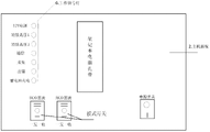
As shown in Figure 1, the present invention includes: industrial carrying case 1, host panel 2, embedded control system, probe segment, accumulator 5, host computer data handling system 16.The upper left corner of industry carrying case 1 bottom is equipped with accumulator 5, other space mounting embedded control systems of bottom, and accumulator 5 is supplied power to embedded control system; Host panel 2 is installed on its upper strata, and host panel 2 links to each other with accumulator 5, embedded control system; Left surface is equipped with notebook adapters in its casing, supplies power to notebook computer; The casing right plate is installed 220V attaching plug 4 and two aviation plugs 3; 220v attaching plug 4 is used for accumulator 5 chargings and notebook adapters charging; Two aviation plugs 3 are connected with probe segment with emission/reception plug for launching plug respectively, select control by the mode switch on the host panel 2.
As shown in Figure 2, the left side of host panel 2 is equipped with working signal lamp 6, shows the duty and the failure message of embedded control system and accumulator 5; The lower right corner is a power switch, the break-make of control total system; Lower left corner Installation Modes switch, the selection of the aviation plug of control detection, when mode switch was pulse echo, aviation plug 3 was the emission plug, when mode switch is one one time receiving, aviation plug 3 is emission/reception plug; The centre is that the notebook computer band is used for fixing notebook computer.
As shown in Figure 3, described embedded control system comprises signal controlling and the processing module of being made up of pumping signal generating unit 7, signal sequence control module 8 and echoed signal processing unit 9, power amplifier module 10 and pre-amplifying module 11; Pumping signal generating unit 7 in signal controlling and the processing module through signal sequence control module 8 with after echoed signal processing unit 9 is connected; The coil adapter 13 of pumping signal generating unit 7 in power amplifier module 10 and probe segment connects, and echoed signal is connected with echoed signal processing unit 9 through pre-amplifying module 11.
As shown in Figure 7; Described pumping signal generating unit 7 comprises that model is FPGA, AD9765 module, the THS3062 module of EP4CE115F29C7N; Receive that FPGA sends by pumping signal being set and producing the pumping signal in two-way phase 1/4 cycle of phasic difference down of host computer data handling system 16 in timing control unit 8 effects, its output terminal links to each other with the input end of power amplifier module 10, employing guided wave direction control technology; Producing the two-way phase differential is the sinusoidal excitation pulse in 1/4 cycle; Guided wave is propagated to strengthening direction, avoided its reciprocal geometric properties signal to rejecting the interference of ripple signal, the amplitude of driving pulse can be provided with as requested; Frequency is 4~250KHZ, 1Hz resolution; Pulse is per second 1~16 pulse;
As shown in Figure 8; The input end of the two-way echoed signal of described echoed signal processing unit 9 is connected with the output terminal of pre-amplifying module 11; Through being sent in the host computer data handling system 16 through the usb data interface by FPGA after the processing of AD9254 module; Function is to convert the two-way analogue echoes voltage signal that carries out the acoustic pressure conversion through pre-amplifying module 11 and amplify to digital signal through A/D; Digital signal utilization Short Time Fourier Transform is carried out time-frequency filtering, send host computer data handling system 16 by FPGA to through the usb data interface then, host computer data handling system 16 is stored demonstration with the result.
As shown in Figure 9; FPGA is connected with host computer data handling system 16 through the usb data interface; Data transmission; The signal sequence control module that signal sequence control module 8 adopts among the FPGA, its function are the sequential between control pumping signal generating unit and the echoed signal processing unit, the time-delay between the time-delay of two-way sinusoidal excitation pulse and the two-way A/D conversion.In the testing process; Same group of probe will be accomplished the dual role of signal excitation and reception; It is different with the work schedule of Echo Processing signal element 9 that this just needs signal sequence control module 8 to control excitation pulse signal unit 7; Owing to adopt the control of guided wave direction, differed for 1/4 cycle equally between the A/D conversion.
Shown in figure 10, described pre-amplifying module 11 has identical two-way, the BPF. that includes three AD817 amplifying circuits and be made up of two ADA4898; Echoed signal is imported by SIGIN, carries out three grades of amplifications through AD817, and the signal after the amplification is the BPF. that U2A, U2B form through two ADA4898 modules; By output terminal O output, output terminal is connected with the input end of Echo Processing unit 9 after the filtering, and function is that the echo voltage signal (voltage peak is about several millivolts) that two-way is faint zooms into the voltage that is fit to A/D and changes (2V extremely+2V); And the echo voltage signal carried out analog filtering; It gains program control adjustable, owing to guided wave can be decayed along with the growth of propagation distance, adopts time controllable gain technology; As time goes on the gain that is pre-amplifying module increases, and can compensate the decay of guided wave.
Shown in figure 11, described power amplifier module 10 has identical two-way, and the output terminal of pumping signal unit 7 is connected with its input end, and signal is U4 through the AD817 module at first by input end W input, and voltage is exaggerated; The AD817 module is that U5, U6 are respectively as homophase, anti-phase unity gain amplifier; Being that to export the LM3886 module to be U7, u9 to one road differential signal through the conversion of signals after amplifying behind the U4; As the differential power amplifier stage; Exporting drive coil 12 from output terminal LN, LP after the differential signal power amplification of U5, U6 output; Function is the pulsed power signal (peak-to-peak value 80v) that two-way sinusoidal excitation pulse (voltage peak is lower than 3.5V) is zoomed into the coil 12 that is applied to probe segment, and its frequency of operation is 4~250KHz.
Be illustrated in figure 4 as guided wave direction control principle figure, because guided wave can be propagated to the both sides of pipeline, in guided wave detects, often pay close attention to the geometric properties of a certain direction, its reciprocal geometric properties signal can cause interference to echoed signal.In order to reduce this interference, the present invention has adopted guided wave direction control technology, when excitation and reception guided wave, reduces non-detection direction signal, strengthens detecting direction signal.
Shown in Fig. 4 a, during the excitation guided wave, propagate to strengthening direction in order to make guided wave, to control the second tunnel pumping signal f2 and delayed time for 1/4 cycle with respect to first via pumping signal f1, the part 2 of the part 1 of coil 12 and coil 12 is spaced apart 1/4 girth.At this moment, pumping signal f1, f2 are at the phase difference φ ' that strengthens the corresponding guided wave component f1 ' of direction, f2 ' and at the phase difference φ that weakens the corresponding guided wave component f1 of direction ", f2 " " can calculate by following method:
Strengthen direction: Δ φ '=φ 1 '-φ 2 '=k (x1 '-x2 ')+ω (t1-t2)
In the formula: φ 1 ', φ 2 ': f1 ', f2 ' phasing degree;
X1 ', x2 ': 2 parts of the part 1 of coil 12 and coil 1 are strengthened the distance of direction RP relatively;
T1, t2:f1, f2 relative reference time constantly;
K: wave number; ω: angular frequency.
Obviously,
 is so Δ φ '=0.At this moment, guided wave is strengthened in the reinforcement direction.
Weaken direction: Δ φ "=φ 1 "-φ 2 "=k (x1 "-x2 ")+ω (t1-t2)
In the formula:
X1 ", x2 ": the part 2 of the part 1 of coil 12 and coil 12 weakens the distance of direction RP relatively;
T1, t2:f1, f2 relative reference time constantly;
K: wave number; ω: angular frequency.
Obviously;

 thus
thus
 at this moment, guided wave is weakened weakening direction.
Similarly; Shown in Fig. 4 b, when receiving echo, for the guided wave that makes specific direction (sensitive direction) is accepted; Control first via echoed signal r1 delayed time for 1/4 cycle with respect to the second tunnel echoed signal r2, and the part 2 of the part 1 of coil 12 and coil 12 is spaced apart 1/4 wavelength.At this moment, the phase differential ΔΦ of sensitive direction echoed signal r1, r2 ' and the phase differential ΔΦ of non-sensitive direction echoed signal r1, r2 " can calculate by following method:
Sensitive direction: ΔΦ '=Φ 1 '-Φ 2 '=k (X1 '-X2 ')+ω (T1-T2)
In the formula:
Φ 1 ', Φ 2 ': r1, r2 phasing degree;
X1 ', X2 ': the distance of the relative sensitive direction RP of the part 1 of coil 12 and part 2;
T1, T2:r1, r2 relative reference time constantly;
K: wave number; ω: angular frequency.
Obviously,
 is so ΔΦ '=0.At this moment, strengthened after echoed signal r1, the r2 stack.
Non-sensitive direction: ΔΦ '=Φ 1 '-Φ 2 '=k (X1 '-X2 ')+ω (T1-T2)
In the formula:
Φ 1 ', Φ 2 ': r1, r2 phasing degree;
X1 ', X2 ': the distance of the relative sensitive direction RP of the part 1 of coil 12 and part 2;
T1, T2:r1, r2 relative reference time constantly;
K: wave number; ω: angular frequency.
Obviously,
 is so ΔΦ "=0.At this moment, weakened after echoed signal r1, the r2 stack.
The time-delay of echoed signal can realize through the sequential by the 8 control A/D conversions of signal sequence control module;
As shown in Figure 5; Adopt Short Time Fourier Transform that signal is carried out time-frequency filtering; Avoided the power spectrum of traditional Fourier transform can not reflect frequency shortcoming over time; Short time discrete Fourier transform is to describe the energy density of signal in different time and frequency through the associating function of time and frequency, is fit to very much the analysis to guided wave signals.
The step of signal Processing is: at first come intercept signal with window function; Putative signal is stably in window, adopts Fourier transform to come signal in the analysis window, so that confirm the frequency in that time existence; Move window function along signal then, obtain signal frequency and concern over time.After obtaining Short Time Fourier Transform, set the threshold value of a frequency energy, the frequency below the threshold value is filtered, obtain filtered signal through Fourier inversion in short-term then.
As shown in Figure 6, pipe element is that 4.1m is long in this instance, and 3 defectives are arranged on it; Be respectively 2 transverse defects and 1 boring; Particular location is as shown in the figure, and the magnetostriction band can be used iron-nickel alloy, nickel cobalt (alloy), ferrocobalt, and this instance adopts ferrocobalt.
Figure 12 is this instance filtered final result figure.
The practical implementation step is following:
1) with being ferrocobalt in 14 examples of magnetostriction band, is coupling in above the tested pipeline 15, and magnetizes circumferential bias magnetic field of generation;
2) after the ferrocobalt bar fixes, coil 12 is linked to each other with the aviation plug 2 of industrial carrying case 1 above it and through coil adapter 13, system powers on, and the mode switch of host panel 2 is chosen as pulse echo;
3) amplitude of setting pumping signal by host computer data handling system 16 is 3V, frequency 64K; Pulse number is 3; Set the back and pass to pumping signal generating unit 7 by the usb data-interface; Under the effect of signal sequence control module 8, producing the two-way phase differential is the sinusoidal excitation pulse in 1/4 cycle, amplifies the after-applied coil 12 of giving probe segment through power amplifier module 10, produces an excitation field; Excitation field and bias magnetic field are quadratures, produce torsional wave by the graceful effect of Wei De, and torsional wave is propagated in pipeline 15; Reflect after running into defective, produce echo and propagate loop line circle 12, by inverted Wiedemann effect; Induce the two-way analog voltage signal of echoed signal in the coil
4) adopt guided wave direction control technology, pumping signal unit 7 two-way phase differential are the sinusoidal excitation pulse in 1/4 cycle, and the part 1 of coil 12 and part 2 are spaced apart 1/4 guide wavelength
5) the two-way analog voltage signal amplifies through pre-amplifying module 11, carries out A/D by echoed signal processing unit 9 and converts digital signal utilization Short Time Fourier Transform to signal is carried out time-frequency filtering, reads in then to store in the host computer and show;
6) host computer data handling system 16 is analyzed identification with the waveform that collects and is judged, confirms the defective of tested member, situations such as the position of defective, quantity, size, classification, and the actual detected waveform is shown in figure 12, and is stored in the computing machine.The end face signal of negative direction is little more than forward and reverse end face signal among Figure 12, can prove, the present invention can accomplish the control of guided wave direction fully, realizes unidirectional detection, and obvious for the defects detection effect more than 2%.
Claims (7)
1. a magnetic striction wave guide detector is characterized in that: comprise host computer data handling system (16), embedded control system and probe segment; Signal controlling in the embedded control system is connected with host computer data handling system (16) with processing module, in coil adapter (13) in the probe segment and the embedded control system
Power amplifier module (10) is connected with pre-amplifying module (11); Magnetostriction band (14) in the probe segment is bonded at epoxy resin or mechanical system directly is coupling in and detects pipeline (15) and go up and magnetize, and the outside that coil (12) wraps in magnetostriction band (14) is connected with power amplifier module (10) with coil adapter (13).
2. a kind of magnetic striction wave guide detector according to claim 1; It is characterized in that: described embedded control system comprises signal controlling and the processing module of being made up of pumping signal generating unit (7), signal sequence control module (8) and echoed signal processing unit (9), power amplifier module (10) and pre-amplifying module (11); Pumping signal generating unit (7) in signal controlling and the processing module through signal sequence control module (8) with after echoed signal processing unit (9) is connected; Pumping signal generating unit (7) is connected with coil adapter (13) in the probe segment through power amplifier module (10), and echoed signal is connected with echoed signal processing unit (9) through pre-amplifying module (11).
3. a kind of magnetic striction wave guide detector according to claim 2 is characterized in that: described pumping signal generating unit (7) comprises that model is FPGA, AD9765 module, the THS3062 module of EP4CE115F29C7N; Receive that FPGA sends by host computer disposal system (16) pumping signal is set and in signal sequence control module (8) the effect pumping signal in generation two-way phase 1/4 cycle of phasic difference down, its output terminal links to each other with the input end of power amplifier module (10).
4. a kind of magnetic striction wave guide detector according to claim 2 is characterized in that: described signal sequence control module (8) adopts the signal sequence control module on the FPGA.
5. a kind of magnetic striction wave guide detector according to claim 2; It is characterized in that: the input end of the two-way echoed signal of described echoed signal processing unit (9) is connected with the output terminal of pre-amplifying module (11), through being sent in the host computer data handling system through the usb data interface by FPGA after the processing of AD9254 module.
6. a kind of magnetic striction wave guide detector according to claim 2; It is characterized in that: described pre-amplifying module (11) has identical two-way; The BPF. that includes three AD817 amplifying circuit U8, U10, U11 and form by two ADA4898; Echoed signal is imported by SIGIN, carries out three grades of amplifications through AD817, and the signal after the amplification is the BPF. that U2A, U2B form through two ADA4898 modules; By output terminal O output, output terminal is connected with the input end of echoed signal processing unit (9) after the filtering.
7. a kind of magnetic striction wave guide detector according to claim 2; It is characterized in that: described power amplifier module (10) has identical two-way; The output terminal of pumping signal generating unit (7) is connected with its input end; Signal is that U4 voltage is exaggerated through the AD817 module at first by input end W input; The AD817 module is that U5, U6 are respectively as homophase, anti-phase unity gain amplifier; Being that to export the LM3886 module to be U7, u9 to one road differential signal through the conversion of signals after amplifying behind the module U4; As the differential power amplifier stage, exporting drive coil (12) from output terminal LN, LP after the differential signal power amplification of U5, U6 output.
Priority Applications (1)
| Application Number | Priority Date | Filing Date | Title |
|---|---|---|---|
| CN2011104179854A CN102520065A (en) | 2011-12-14 | 2011-12-14 | Magnetostriction guided wave detector |
Applications Claiming Priority (1)
| Application Number | Priority Date | Filing Date | Title |
|---|---|---|---|
| CN2011104179854A CN102520065A (en) | 2011-12-14 | 2011-12-14 | Magnetostriction guided wave detector |
Publications (1)
| Publication Number | Publication Date |
|---|---|
| CN102520065A true CN102520065A (en) | 2012-06-27 |
Family
ID=46291053
Family Applications (1)
| Application Number | Title | Priority Date | Filing Date |
|---|---|---|---|
| CN2011104179854A Pending CN102520065A (en) | 2011-12-14 | 2011-12-14 | Magnetostriction guided wave detector |
Country Status (1)
| Country | Link |
|---|---|
| CN (1) | CN102520065A (en) |
Cited By (14)
| Publication number | Priority date | Publication date | Assignee | Title |
|---|---|---|---|---|
| CN103235046A (en) * | 2013-05-09 | 2013-08-07 | 哈尔滨工业大学 | One-way launching electromagnetic ultrasonic surface wave transducer and method adopting transducer to detect metal surface defect |
| CN103675099A (en) * | 2013-12-16 | 2014-03-26 | 杭州浙大精益机电技术工程有限公司 | Rail flange defect monitoring system and method based on magnetostrictive torsional guided waves |
| CN103743810A (en) * | 2013-12-24 | 2014-04-23 | 华中科技大学 | Magnetostriction guided wave detection signal processing method and device |
| CN103822973A (en) * | 2014-02-26 | 2014-05-28 | 北京工业大学 | Omnidirectional shear-horizontal-mode magnetostrictive transducer |
| CN104122329A (en) * | 2014-07-22 | 2014-10-29 | 华中科技大学 | Detection sensor based on magnetostriction guide waves, detection system and application |
| CN105301117A (en) * | 2015-10-14 | 2016-02-03 | 浙江大学 | Method for detecting peripheral defect of hollow cylinder by ultrasonic frequency dispersion compensation principle |
| CN105651859A (en) * | 2016-01-12 | 2016-06-08 | 杭州浙达精益机电技术股份有限公司 | Ultrasonic guided wave device and method for monitoring corrosion of pipeline |
| CN105675726A (en) * | 2016-01-12 | 2016-06-15 | 浙江大学 | Multilayer stackable magnetostriction shearing mode ultrasonic guided-wave emitter |
| CN106066365A (en) * | 2016-08-22 | 2016-11-02 | 中国石油化工股份有限公司 | Storage tank bottom plate In-service testing System and method for based on mangneto formula horizontal shear wave |
| CN106950281A (en) * | 2017-03-29 | 2017-07-14 | 国网浙江省电力公司电力科学研究院 | High-tension cable aluminium sheath detecting system and detection method based on mangneto formula torsional wave |
| CN107102055A (en) * | 2017-04-25 | 2017-08-29 | 武汉中科创新技术股份有限公司 | Electromagnetic ultrasonic guide wave probe detector |
| CN110174462A (en) * | 2019-06-06 | 2019-08-27 | 广西电网有限责任公司电力科学研究院 | The magnetostrictive ultrasonic Guided waves system and its detection method of special operation condition pipe |
| CN111562306A (en) * | 2020-05-01 | 2020-08-21 | 湖北三江航天万峰科技发展有限公司 | A magnetostrictive guided wave detection system |
| CN113028965A (en) * | 2021-03-10 | 2021-06-25 | 国家石油天然气管网集团有限公司华南分公司 | Giant magnetoresistance detection device of magnetostrictive displacement sensor |
Citations (7)
| Publication number | Priority date | Publication date | Assignee | Title |
|---|---|---|---|---|
| JP2006329868A (en) * | 2005-05-27 | 2006-12-07 | Hitachi Ltd | Electromagnetic ultrasonic flaw detection method and electromagnetic ultrasonic flaw detection apparatus |
| CN1898558A (en) * | 2003-11-13 | 2007-01-17 | 西南研究院 | Method and system for torsional wave inspection of heat exchanger tubes |
| US20070090904A1 (en) * | 2005-10-20 | 2007-04-26 | Seoul National University Industry Foundation | Method of generating and measuring torsional waves in cylindrical structure using magnetostrictive effect, and magnetostrictive transducer and structure diagnosis apparatus using the method |
| CN101173911A (en) * | 2007-10-17 | 2008-05-07 | 中国人民解放军海军工程大学 | A rapid scanning method for pipeline defects and a non-destructive testing device |
| US7573261B1 (en) * | 2008-06-20 | 2009-08-11 | Ihi Southwest Technologies, Inc. | Method and system for the generation of torsional guided waves using a ferromagnetic strip sensor |
| KR101068350B1 (en) * | 2009-07-03 | 2011-09-28 | (주)디지털초음파 | Contact Sh-Wave Magnetostrictive Transducer |
| CN202362276U (en) * | 2011-12-14 | 2012-08-01 | 杭州浙大精益机电技术工程有限公司 | Magnetostrictive guided wave detector |
-
2011
- 2011-12-14 CN CN2011104179854A patent/CN102520065A/en active Pending
Patent Citations (7)
| Publication number | Priority date | Publication date | Assignee | Title |
|---|---|---|---|---|
| CN1898558A (en) * | 2003-11-13 | 2007-01-17 | 西南研究院 | Method and system for torsional wave inspection of heat exchanger tubes |
| JP2006329868A (en) * | 2005-05-27 | 2006-12-07 | Hitachi Ltd | Electromagnetic ultrasonic flaw detection method and electromagnetic ultrasonic flaw detection apparatus |
| US20070090904A1 (en) * | 2005-10-20 | 2007-04-26 | Seoul National University Industry Foundation | Method of generating and measuring torsional waves in cylindrical structure using magnetostrictive effect, and magnetostrictive transducer and structure diagnosis apparatus using the method |
| CN101173911A (en) * | 2007-10-17 | 2008-05-07 | 中国人民解放军海军工程大学 | A rapid scanning method for pipeline defects and a non-destructive testing device |
| US7573261B1 (en) * | 2008-06-20 | 2009-08-11 | Ihi Southwest Technologies, Inc. | Method and system for the generation of torsional guided waves using a ferromagnetic strip sensor |
| KR101068350B1 (en) * | 2009-07-03 | 2011-09-28 | (주)디지털초음파 | Contact Sh-Wave Magnetostrictive Transducer |
| CN202362276U (en) * | 2011-12-14 | 2012-08-01 | 杭州浙大精益机电技术工程有限公司 | Magnetostrictive guided wave detector |
Non-Patent Citations (4)
| Title |
|---|
| YI-GON KIM, ET AL: "Generating and detecting torsional guided waves using magnetostrictive sensors of crossed coils", 《NDT & E INTERNATIONAL》, vol. 44, no. 2, 31 March 2011 (2011-03-31), pages 145 - 151 * |
| YOON YOUNG KIM, ET AL: "Torsional wave experiments with a new magnetostrictive transducer configuration", 《JOURNAL OF THE ACOUSTICAL SOCIETY OF AMERICA》, vol. 117, no. 6, 30 June 2005 (2005-06-30), pages 3459 - 3468 * |
| 冯红亮等: "一种磁致伸缩式超声波激发/接收传感器的研究", 《仪表技术与传感器》, no. 07, 25 July 2003 (2003-07-25) * |
| 徐书根等: "磁致伸缩导波技术检测管道缺陷", 《无损检测》, no. 07, 10 July 2008 (2008-07-10) * |
Cited By (22)
| Publication number | Priority date | Publication date | Assignee | Title |
|---|---|---|---|---|
| CN103235046A (en) * | 2013-05-09 | 2013-08-07 | 哈尔滨工业大学 | One-way launching electromagnetic ultrasonic surface wave transducer and method adopting transducer to detect metal surface defect |
| CN103675099A (en) * | 2013-12-16 | 2014-03-26 | 杭州浙大精益机电技术工程有限公司 | Rail flange defect monitoring system and method based on magnetostrictive torsional guided waves |
| CN103675099B (en) * | 2013-12-16 | 2016-05-04 | 杭州浙达精益机电技术股份有限公司 | Reverse the flange of rail defect inspection system and method for guided wave based on magnetostriction |
| CN103743810A (en) * | 2013-12-24 | 2014-04-23 | 华中科技大学 | Magnetostriction guided wave detection signal processing method and device |
| CN103743810B (en) * | 2013-12-24 | 2016-05-25 | 华中科技大学 | A kind of magnetic striction wave guide detection signal processing method and device |
| CN103822973A (en) * | 2014-02-26 | 2014-05-28 | 北京工业大学 | Omnidirectional shear-horizontal-mode magnetostrictive transducer |
| CN104122329A (en) * | 2014-07-22 | 2014-10-29 | 华中科技大学 | Detection sensor based on magnetostriction guide waves, detection system and application |
| CN104122329B (en) * | 2014-07-22 | 2016-06-01 | 华中科技大学 | Based on the detecting sensor of magnetic striction wave guide, detection system and application |
| CN105301117A (en) * | 2015-10-14 | 2016-02-03 | 浙江大学 | Method for detecting peripheral defect of hollow cylinder by ultrasonic frequency dispersion compensation principle |
| CN105301117B (en) * | 2015-10-14 | 2017-11-10 | 浙江大学 | A kind of method that hollow cylinder circumferential defect is detected with ultrasonic frequency dispersion compensation principle |
| CN105675726A (en) * | 2016-01-12 | 2016-06-15 | 浙江大学 | Multilayer stackable magnetostriction shearing mode ultrasonic guided-wave emitter |
| CN105651859A (en) * | 2016-01-12 | 2016-06-08 | 杭州浙达精益机电技术股份有限公司 | Ultrasonic guided wave device and method for monitoring corrosion of pipeline |
| CN105675726B (en) * | 2016-01-12 | 2018-06-19 | 浙江大学 | Mode supersonic guide-wave transmitter is sheared in a kind of multiple-level stack formula magnetostriction |
| CN105651859B (en) * | 2016-01-12 | 2018-08-14 | 杭州浙达精益机电技术股份有限公司 | Pipe ultrasonic guided wave corrosion monitor and method |
| CN106066365A (en) * | 2016-08-22 | 2016-11-02 | 中国石油化工股份有限公司 | Storage tank bottom plate In-service testing System and method for based on mangneto formula horizontal shear wave |
| CN106066365B (en) * | 2016-08-22 | 2019-04-09 | 中国石油化工股份有限公司 | In-service detection system and method for storage tank floor based on magnetically induced horizontal shear wave |
| CN106950281A (en) * | 2017-03-29 | 2017-07-14 | 国网浙江省电力公司电力科学研究院 | High-tension cable aluminium sheath detecting system and detection method based on mangneto formula torsional wave |
| CN107102055A (en) * | 2017-04-25 | 2017-08-29 | 武汉中科创新技术股份有限公司 | Electromagnetic ultrasonic guide wave probe detector |
| CN110174462A (en) * | 2019-06-06 | 2019-08-27 | 广西电网有限责任公司电力科学研究院 | The magnetostrictive ultrasonic Guided waves system and its detection method of special operation condition pipe |
| CN110174462B (en) * | 2019-06-06 | 2024-07-19 | 广西电网有限责任公司电力科学研究院 | Magnetostrictive ultrasonic guided wave detection system and detection method for special working condition pipes |
| CN111562306A (en) * | 2020-05-01 | 2020-08-21 | 湖北三江航天万峰科技发展有限公司 | A magnetostrictive guided wave detection system |
| CN113028965A (en) * | 2021-03-10 | 2021-06-25 | 国家石油天然气管网集团有限公司华南分公司 | Giant magnetoresistance detection device of magnetostrictive displacement sensor |
Similar Documents
| Publication | Publication Date | Title |
|---|---|---|
| CN102520065A (en) | Magnetostriction guided wave detector | |
| CN202362276U (en) | Magnetostrictive guided wave detector | |
| CN101672429B (en) | Oil pipeline inspection system | |
| CN102537669B (en) | A pipeline defect detection method and system based on ultrasonic guided wave focusing | |
| CN103196991B (en) | The all standing transient electromagnetic detection method of the metal erosion of continuous diagnosis body and defect | |
| CN101666783A (en) | Ultrasonic guided wave composite non-destructive testing method and device | |
| CN102980942B (en) | Metal pipeline detection method | |
| CN103926313A (en) | Composite material porosity value evaluation method based on ultrasonic detection | |
| Brockhaus et al. | In-line inspection (ILI) methods for detecting corrosion in underground pipelines | |
| CN103217480B (en) | Ultrasonic guided-wave judging method for pipe cross section loss amount | |
| CN103323529A (en) | Method for identifying ultrasonic guided wave of oblique crack pipeline through utilizing improved Duffing chaotic system | |
| Yue et al. | Applicability analysis of inspection and monitoring technologies in wind turbine towers | |
| Shi et al. | A fatigue crack prediction method based on inductive semi-supervised learning and Lamb-wave monitoring for orthotropic steel bridge deck | |
| CN106053602A (en) | A self-closed rock bolt nondestructive testing method based on a magnetostrictive effect | |
| CN205449361U (en) | Residual stress test equipment | |
| CN104034800A (en) | Assessment method and system for hydraulic detection of conveying pipeline and for state of carrier fluid pipeline | |
| Kurz et al. | NDT for need based maintenance of bridge cables, ropes and pre-stressed elements | |
| CN100374819C (en) | Non-destructive detection method of bolt length embedded in different media by using ultrasonic guided wave | |
| CN202402950U (en) | Portable pipe corrosion and leakage on-site detecting device | |
| Tan et al. | Structural health monitoring of bridges using acoustic emission technology | |
| CN110133105A (en) | A non-contact non-destructive testing method for the strength of water-immersed concrete | |
| CN120404933A (en) | An acoustic, magnetic and electric pipeline detection system, method, storage medium and product | |
| CN202994734U (en) | Pipeline detection system | |
| CN203275369U (en) | System for measuring steel rail crack abrasion on basis of surface wave method | |
| Elwalwal et al. | Crack inspection using guided waves (GWs)/structural health monitoring (SHM) |
Legal Events
| Date | Code | Title | Description |
|---|---|---|---|
| C06 | Publication | ||
| PB01 | Publication | ||
| C53 | Correction of patent of invention or patent application | ||
| CB02 | Change of applicant information |
Address after: Yuhang District, Hangzhou City, Zhejiang Province, 310030 West No. 1500 Building No. 1 room 107 Applicant after: Hangzhou Zheda Jingyi Electromechanical Technology Engineering Co., Ltd. Address before: Hangzhou City, Zhejiang province 310030 nine road, West Lake science and Technology Economic Zone No. seven building 3 floor Applicant before: Hangzhou Zheda Jingyi Electromechanical Technology Engineering Co., Ltd. |
|
| C10 | Entry into substantive examination | ||
| SE01 | Entry into force of request for substantive examination | ||
| C02 | Deemed withdrawal of patent application after publication (patent law 2001) | ||
| WD01 | Invention patent application deemed withdrawn after publication |
Application publication date: 20120627 |