CN102449268A - turbine - Google Patents
turbine Download PDFInfo
- Publication number
- CN102449268A CN102449268A CN2010800231932A CN201080023193A CN102449268A CN 102449268 A CN102449268 A CN 102449268A CN 2010800231932 A CN2010800231932 A CN 2010800231932A CN 201080023193 A CN201080023193 A CN 201080023193A CN 102449268 A CN102449268 A CN 102449268A
- Authority
- CN
- China
- Prior art keywords
- blade
- steam
- sealing lug
- upstream side
- chamber
- Prior art date
- Legal status (The legal status is an assumption and is not a legal conclusion. Google has not performed a legal analysis and makes no representation as to the accuracy of the status listed.)
- Granted
Links
Images


Classifications
-
- F—MECHANICAL ENGINEERING; LIGHTING; HEATING; WEAPONS; BLASTING
- F16—ENGINEERING ELEMENTS AND UNITS; GENERAL MEASURES FOR PRODUCING AND MAINTAINING EFFECTIVE FUNCTIONING OF MACHINES OR INSTALLATIONS; THERMAL INSULATION IN GENERAL
- F16J—PISTONS; CYLINDERS; SEALINGS
- F16J15/00—Sealings
- F16J15/44—Free-space packings
- F16J15/447—Labyrinth packings
- F16J15/4472—Labyrinth packings with axial path
-
- F—MECHANICAL ENGINEERING; LIGHTING; HEATING; WEAPONS; BLASTING
- F01—MACHINES OR ENGINES IN GENERAL; ENGINE PLANTS IN GENERAL; STEAM ENGINES
- F01D—NON-POSITIVE DISPLACEMENT MACHINES OR ENGINES, e.g. STEAM TURBINES
- F01D11/00—Preventing or minimising internal leakage of working-fluid, e.g. between stages
- F01D11/001—Preventing or minimising internal leakage of working-fluid, e.g. between stages for sealing space between stator blade and rotor
-
- F—MECHANICAL ENGINEERING; LIGHTING; HEATING; WEAPONS; BLASTING
- F01—MACHINES OR ENGINES IN GENERAL; ENGINE PLANTS IN GENERAL; STEAM ENGINES
- F01D—NON-POSITIVE DISPLACEMENT MACHINES OR ENGINES, e.g. STEAM TURBINES
- F01D11/00—Preventing or minimising internal leakage of working-fluid, e.g. between stages
- F01D11/02—Preventing or minimising internal leakage of working-fluid, e.g. between stages by non-contact sealings, e.g. of labyrinth type
-
- F—MECHANICAL ENGINEERING; LIGHTING; HEATING; WEAPONS; BLASTING
- F01—MACHINES OR ENGINES IN GENERAL; ENGINE PLANTS IN GENERAL; STEAM ENGINES
- F01D—NON-POSITIVE DISPLACEMENT MACHINES OR ENGINES, e.g. STEAM TURBINES
- F01D11/00—Preventing or minimising internal leakage of working-fluid, e.g. between stages
- F01D11/08—Preventing or minimising internal leakage of working-fluid, e.g. between stages for sealing space between rotor blade tips and stator
-
- F—MECHANICAL ENGINEERING; LIGHTING; HEATING; WEAPONS; BLASTING
- F01—MACHINES OR ENGINES IN GENERAL; ENGINE PLANTS IN GENERAL; STEAM ENGINES
- F01D—NON-POSITIVE DISPLACEMENT MACHINES OR ENGINES, e.g. STEAM TURBINES
- F01D5/00—Blades; Blade-carrying members; Heating, heat-insulating, cooling or antivibration means on the blades or the members
- F01D5/12—Blades
- F01D5/14—Form or construction
- F01D5/20—Specially-shaped blade tips to seal space between tips and stator
-
- F—MECHANICAL ENGINEERING; LIGHTING; HEATING; WEAPONS; BLASTING
- F01—MACHINES OR ENGINES IN GENERAL; ENGINE PLANTS IN GENERAL; STEAM ENGINES
- F01D—NON-POSITIVE DISPLACEMENT MACHINES OR ENGINES, e.g. STEAM TURBINES
- F01D5/00—Blades; Blade-carrying members; Heating, heat-insulating, cooling or antivibration means on the blades or the members
- F01D5/12—Blades
- F01D5/22—Blade-to-blade connections, e.g. for damping vibrations
- F01D5/225—Blade-to-blade connections, e.g. for damping vibrations by shrouding
-
- F—MECHANICAL ENGINEERING; LIGHTING; HEATING; WEAPONS; BLASTING
- F02—COMBUSTION ENGINES; HOT-GAS OR COMBUSTION-PRODUCT ENGINE PLANTS
- F02C—GAS-TURBINE PLANTS; AIR INTAKES FOR JET-PROPULSION PLANTS; CONTROLLING FUEL SUPPLY IN AIR-BREATHING JET-PROPULSION PLANTS
- F02C7/00—Features, components parts, details or accessories, not provided for in, or of interest apart form groups F02C1/00 - F02C6/00; Air intakes for jet-propulsion plants
- F02C7/28—Arrangement of seals
Landscapes
- Engineering & Computer Science (AREA)
- General Engineering & Computer Science (AREA)
- Mechanical Engineering (AREA)
- Chemical & Material Sciences (AREA)
- Combustion & Propulsion (AREA)
- Turbine Rotor Nozzle Sealing (AREA)
- Sealing Using Fluids, Sealing Without Contact, And Removal Of Oil (AREA)
Abstract
Description
技术领域 technical field
本发明涉及例如发电设备、化学设备、气体设备、钢铁厂、船舶等所使用的涡轮。The present invention relates to turbines used in, for example, power generation equipment, chemical equipment, gas equipment, steel mills, ships, and the like.
本申请基于2009年10月9日在日本申请的JP特愿2009-235430号而主张优先权,在此援引其内容。this application claims priority based on JP Japanese Patent Application No. 2009-235430 for which it applied to Japan on October 9, 2009, and uses the content here.
背景技术 Background technique
众所周知,作为蒸汽轮机的一种,存在包括汽缸、在汽缸的内部可旋转地设置的轴体(转子)、在汽缸的内周部固定而配置的多个静叶片、在这些多个静叶片的下游侧(蒸汽的流动的下游侧)呈放射状设于轴体的多个动叶片的蒸汽轮机。这种蒸汽轮机中的冲动式涡轮通过静叶片将蒸汽的压力能量变换成速度能量,通过动叶片将该速度能量变换成旋转能量(机械能量)。另外,反动式涡轮也在动叶片内将压力能量变换成速度能量,通过蒸汽喷出的反作用力变换成旋转能量(机械能量)。As is well known, one type of steam turbine includes a cylinder, a shaft (rotor) rotatably provided inside the cylinder, a plurality of stationary vanes fixed and arranged on the inner peripheral portion of the cylinder, and the The downstream side (the downstream side of the flow of steam) is a steam turbine with a plurality of rotor blades radially provided on the shaft body. The impulsive turbine among such steam turbines converts the pressure energy of steam into velocity energy through the stationary blades, and converts the velocity energy into rotational energy (mechanical energy) through the moving blades. In addition, the reaction turbine converts pressure energy into velocity energy in the moving blades, and converts the reaction force of steam ejection into rotational energy (mechanical energy).
这种蒸汽轮机中,通常在动叶片的前端部和环绕动叶片而形成蒸汽流路的汽缸之间形成径向的间隙。另外,在静叶片的前端部和轴体之间也形成径向的间隙。但是,在动叶片的前端部的间隙中向下游侧通过的泄漏蒸汽不对动叶片施加旋转力。另外,在静叶片前端部的间隙中向下游侧通过的泄漏蒸汽不利用静叶片将压力能量变换成速度能量,因此对下游的动叶片几乎不施加旋转力。因此,为了提高蒸汽轮机的性能,减少通过动叶片的前端部的间隙的泄漏蒸汽的量是重要的。In such a steam turbine, a radial gap is generally formed between the tip of the rotor blade and a cylinder that forms a steam flow path around the rotor blade. In addition, radial gaps are also formed between the tip portions of the stator blades and the shaft body. However, the leakage steam passing downstream through the gap at the tip of the rotor blade does not apply a rotational force to the rotor blade. In addition, since the leakage steam passing downstream through the clearance at the front end of the stator blade does not convert the pressure energy into velocity energy by the stator blade, almost no rotational force is applied to the downstream rotor blade. Therefore, in order to improve the performance of the steam turbine, it is important to reduce the amount of leakage steam that passes through the gap at the tip of the rotor blade.
在下述专利文献1中,提出了如下结构:在动叶片的前端部设有高度从轴向(与动叶片的旋转轴平行的方向)上的蒸汽(流体)的流动的上游侧向下游侧逐渐变高的阶梯部。该结构中,设有相对于阶梯部具有间隙的密封凸片。In the following Patent Document 1, a structure is proposed in which the tip of the rotor blade is provided with a height gradually increasing from the upstream side to the downstream side of the flow of steam (fluid) in the axial direction (direction parallel to the rotation axis of the rotor blade). The stepped part that becomes higher. In this structure, the seal fin which has a clearance gap with respect to a stepped part is provided.
通过这种构成,穿过密封凸片的间隙的蒸汽的泄漏流冲击形成阶梯部的台阶面的端缘部,使蒸汽的流动阻力增大。由此,减少蒸汽的泄漏流量。With such a configuration, the leakage flow of steam passing through the gaps of the seal fins collides with the edge portion of the stepped surface forming the stepped portion, increasing the flow resistance of the steam. Thereby, the leakage flow rate of steam is reduced.
在先技术文献prior art literature
专利文献patent documents
专利文献1 JP特开2006-291967号公报(图4)Patent Document 1 JP Unexamined Publication No. 2006-291967 (Fig. 4)
发明内容 Contents of the invention
但是,针对提高蒸汽轮机的性能的要求加强了,因此要求进一步减少蒸汽的泄漏流量。However, the demand for improvement of the performance of the steam turbine has been strengthened, and therefore the leakage flow rate of steam has been further reduced.
本发明考虑此种问题而创立,其目的是提供进一步减少流体的泄漏流量的高性能涡轮。The present invention was made in consideration of such a problem, and an object of the present invention is to provide a high-performance turbine that further reduces the leakage flow rate of fluid.
本发明的涡轮具备:叶片;经由间隙设于所述叶片的前端侧并且相对于所述叶片相对旋转的结构体。在该涡轮中,在所述叶片的前端部侧和与所述结构体的所述前端部对应的部分中的一方上设有具有台阶面而向另一侧突出的阶梯部,在另一方上,设有相对于所述阶梯部延伸而在与该阶梯部之间形成微小间隙H的密封凸片。此处,在所述叶片的前端部与所述结构体的所述部分之间,在所述密封凸片与相对于该密封凸片在所述结构体的旋转轴向上游侧相对的隔壁之间形成腔室。另外,将所述腔室的、所述隔壁与所述密封凸片之间的距离设为腔室宽度W。此时,将所述密封凸片与所述阶梯部的所述旋转轴向上游侧的端缘部之间的距离设为L时,该距离L中的至少1个满足以下的式(1)。The turbine according to the present invention includes: a blade; and a structure that is provided on the front end side of the blade through a gap and relatively rotates with respect to the blade. In this turbine, a stepped portion having a stepped surface protruding to the other side is provided on one of the front end side of the blade and a portion corresponding to the front end portion of the structure, and on the other side , there is provided a sealing fin extending relative to the stepped portion to form a small gap H with the stepped portion. Here, between the front end portion of the vane and the portion of the structural body, between the seal fin and the partition wall opposite to the seal fin on the upstream side of the rotational axis of the structural body A chamber is formed. In addition, the distance between the partition wall and the seal fin in the chamber is defined as a chamber width W. At this time, assuming that the distance between the seal fin and the end edge portion of the stepped portion on the upstream side of the rotational axis is L, at least one of the distances L satisfies the following expression (1). .
0.7H≤L≤0.3W……(1)0.7H≤L≤0.3W...(1)
即,上述的涡轮是将流体的能量变换成旋转能量的涡轮。上述的涡轮的第1方式包括以下部件:叶片;在与所述叶片的前端部之间具有间隙,并相对于所述叶片相对旋转的结构体;设于所述叶片的前端部,具有台阶面而朝向所述结构体突出的阶梯部;设于所述结构体,朝向所述阶梯部延伸的密封凸片;相对于所述密封凸片在与所述叶片或所述结构体的旋转轴平行的方向上的所述流体的流动的上游侧相对的隔壁;在所述叶片的前端部与所述结构体之间且所述隔壁与所述密封凸片之间形成的腔室。That is, the aforementioned turbine is a turbine that converts fluid energy into rotational energy. The first aspect of the above-mentioned turbine includes the following components: a blade; a structure that has a gap between the front end of the blade and rotates relative to the blade; is provided at the front end of the blade and has a stepped surface The stepped portion protruding toward the structure; the sealing fin provided on the structure and extending toward the stepped portion; relative to the sealing fin in parallel with the rotation axis of the blade or the structure a partition wall opposite to the upstream side of the flow of the fluid in the direction; a cavity formed between the front end portion of the vane and the structure body and between the partition wall and the sealing fin.
另外,上述的涡轮的第2方式包括以下部件:叶片;在与所述叶片的前端部之间具有间隙,并相对于所述叶片相对旋转的结构体;设于所述结构体,具有台阶面而朝向所述叶片的前端部突出的阶梯部;设于所述叶片的前端部,朝向所述阶梯部延伸的密封凸片;相对于所述密封凸片在与所述叶片或所述结构体的旋转轴平行的方向上的所述流体的流动的上游侧相对的隔壁;在所述叶片的前端部与所述结构体之间且所述隔壁与所述密封凸片之间形成的腔室。In addition, the above-mentioned second aspect of the turbine includes the following components: a blade; a structure that has a gap between the front end of the blade and rotates relative to the blade; and is provided on the structure and has a stepped surface. And the stepped portion protruding toward the front end of the blade; the sealing fin provided at the front end of the blade and extending toward the stepped portion; relative to the sealing fin in relation to the blade or the structure a partition wall opposite to the upstream side of the flow of the fluid in a direction parallel to the axis of rotation; a cavity formed between the front end portion of the vane and the structure and between the partition wall and the sealing fin .
上述涡轮的第1方式和第2方式中,将所述密封凸片与所述阶梯部之间形成的微小间隙设为H。另外,将形成所述腔室的所述隔壁与所述密封凸片之间的距离设为腔室宽度W。另外,将所述密封凸片与所述阶梯部的所述上游侧的端缘部之间的距离设为L。此时,该距离L中的至少1个满足上述的式(1)。In the first aspect and the second aspect of the above-mentioned turbine, H is the minute gap formed between the seal fin and the stepped portion. In addition, the distance between the partition wall forming the cavity and the seal fin is defined as a cavity width W. In addition, let L be the distance between the said seal fin and the said upstream edge part of the said step part. At this time, at least one of the distances L satisfies the above-mentioned formula (1).
根据该涡轮,流入腔室内的流体冲击形成阶梯部的端缘部的台阶面、即朝向阶梯部的流体的流动的上游侧的面,返回上游侧而产生沿第1方向转动的主涡。另外,此时,特别是在所述台阶面的端缘部(边缘),从所述主涡剥离一部分的流动。由此,产生沿所述第1方向的相反方向转动的剥离涡。该剥离涡发挥减少穿过密封凸片前端和阶梯部之间的微小间隙H的泄漏流的缩流效果。但是,该剥离涡产生的缩流效果,特别是根据所述端缘部的位置(距密封凸片的距离L)与所述微小间隙H的大小之间的关系、进而与腔室宽度W之间的关系而变化。According to this turbine, the fluid flowing into the chamber hits the stepped surface of the edge portion forming the stepped portion, that is, the upstream side surface of the fluid flow of the stepped portion, returns to the upstream side, and generates a main vortex that rotates in the first direction. In addition, at this time, especially at the edge portion (edge) of the step surface, a part of the flow is separated from the main vortex. As a result, a separation vortex that rotates in a direction opposite to the first direction is generated. This separation vortex exerts the vena contracta effect of reducing the leakage flow passing through the minute gap H between the front end of the seal fin and the stepped portion. However, the contraction effect caused by the separation vortex depends on the relationship between the position of the edge portion (distance L from the sealing fin) and the size of the tiny gap H, and the relationship between the width W of the cavity. The relationship between them changes.
因此,基于后述的模拟结果,规定这些关系以满足上述的式(1)。由此,能够充分提高剥离涡产生的缩流效果,从而进一步减少流体的泄漏流量。Therefore, based on the simulation results described later, these relationships are defined so as to satisfy the above-mentioned formula (1). Thereby, the contraction effect of the separation vortex can be sufficiently enhanced, thereby further reducing the leakage flow rate of the fluid.
另外,所述涡轮中,所述距离L也可以满足以下的式(2)。In addition, in the turbine, the distance L may satisfy the following expression (2).
1.25H≤L≤2.75H(其中,L≤0.3W)……(2)1.25H≤L≤2.75H (where L≤0.3W)...(2)
由此,如后述的模拟结果所示,剥离涡产生的缩流效果进一步提高,流体的泄漏流量进一步减少。As a result, as shown by the simulation results described later, the contraction effect of the separation vortex is further enhanced, and the leakage flow rate of the fluid is further reduced.
另外,所述涡轮中,所述阶梯部也可以以突出高度从所述旋转轴向上游侧朝向下游侧逐渐变高的方式设置多个。也可以在所述另一方设置相对于各个所述阶梯部延伸的所述密封凸片。与所述阶梯部对应的密封凸片也可以是相对于与在所述旋转轴向下游侧相邻的阶梯部对应的密封凸片相对的所述隔壁。In addition, in the turbine, a plurality of the stepped portions may be provided such that the protrusion height gradually increases from the upstream side toward the downstream side of the rotating shaft. The seal fins extending with respect to each of the stepped portions may be provided on the other side. The seal fin corresponding to the stepped portion may be the partition wall facing the seal fin corresponding to the stepped portion adjacent to the downstream side in the rotational axis.
即,上述的涡轮的第1方式中,所述阶梯部也可以以朝向所述结构体突出的突出高度从与所述旋转轴平行的方向上的所述流体的流动的上游侧朝向下游侧逐渐变高的方式设置多个。另外,所述结构体上,也可以对应于各个所述阶梯部而设置所述密封凸片。另外,与所述阶梯部对应的密封凸片也可以是相对于与在所述下游侧相邻的阶梯部对应的密封凸片相对的所述隔壁。That is, in the above-mentioned first aspect of the turbine, the step portion may gradually protrude from the upstream side toward the downstream side of the flow of the fluid in the direction parallel to the rotation axis at a protrusion height toward the structure body. Set multiple ways to get higher. In addition, the sealing fins may be provided on the structural body corresponding to the respective stepped portions. In addition, the seal fin corresponding to the step portion may be the partition wall facing the seal fin corresponding to the step portion adjacent to the downstream side.
另外,上述的涡轮的第2方式中,所述阶梯部也可以以朝向所述叶片的前端部突出的突出高度从与所述旋转轴平行的方向上的所述流体的流动的上游侧朝向下游侧逐渐变高的方式设置多个。另外,所述叶片的前端部上,也可以对应于各个所述阶梯部而设置所述密封凸片。另外,与所述阶梯部对应的密封凸片也可以是相对于与在所述下游侧相邻的阶梯部对应的密封凸片相对的所述隔壁。In addition, in the above-mentioned second aspect of the turbine, the step portion may project from the upstream side toward the downstream side of the flow of the fluid in the direction parallel to the rotation axis at a protrusion height toward the tip portion of the blade. The sides are set in a manner that becomes higher gradually. In addition, the sealing fins may be provided on the front end portion of the vane corresponding to each of the stepped portions. In addition, the seal fin corresponding to the step portion may be the partition wall facing the seal fin corresponding to the step portion adjacent to the downstream side.
若如此,则对于每个阶梯部都可得到所述的剥离涡产生的缩流效果。因此叶片与结构体之间的流体的泄漏流量充分减少。In this way, the above-mentioned constriction effect by the separation vortex can be obtained for every step portion. Therefore, the leakage flow rate of the fluid between the vane and the structural body is sufficiently reduced.
此外,该涡轮中,所述结构体的、与所述叶片的前端部对应的部分也可以是以所述旋转轴为中心轴的环状的凹部。另外,相对于与最靠所述上游侧的阶梯部对应的密封凸片相对的所述隔壁也可以由所述凹部的所述上游侧的内壁面形成。In addition, in this turbine, the portion of the structure corresponding to the tip of the blade may be an annular recess with the rotating shaft as a central axis. In addition, the partition wall facing the seal fin corresponding to the most upstream stepped portion may be formed by the upstream inner wall surface of the concave portion.
若如此,则在与叶片或结构体的旋转轴平行的方向上位于流体的流动的最上游侧的阶梯部上,也可得到所述的剥离涡产生的缩流效果。因此叶片与结构体之间的流体的泄漏流量充分减少。In this way, the above-described constriction effect by the separation vortex can also be obtained at the step portion located on the most upstream side of the fluid flow in the direction parallel to the rotation axis of the blade or the structure. Therefore, the leakage flow rate of the fluid between the vane and the structural body is sufficiently reduced.
发明效果Invention effect
根据本发明,能够提供进一步减少流体的泄漏流量的高性能的涡轮。According to the present invention, it is possible to provide a high-performance turbine that further reduces the leakage flow rate of fluid.
附图说明 Description of drawings
图1是表示本发明的蒸汽轮机的概略构成剖视图。Fig. 1 is a cross-sectional view showing a schematic configuration of a steam turbine according to the present invention.
图2是表示本发明的第1实施方式的图,是表示图1中的要部I的放大剖视图。FIG. 2 is a diagram showing a first embodiment of the present invention, and is an enlarged cross-sectional view showing a main part I in FIG. 1 .
图3是表示本发明的第1实施方式的蒸汽轮机的作用说明图。Fig. 3 is an explanatory view showing the operation of the steam turbine according to the first embodiment of the present invention.
图4是表示模拟结果的图表。Fig. 4 is a graph showing simulation results.
图5是图4的范围[1]上的流动模式说明图。Fig. 5 is an explanatory diagram of a flow pattern in the range [1] of Fig. 4 .
图6是图4的范围[2]上的流动模式说明图。Fig. 6 is an explanatory diagram of a flow pattern in the range [2] of Fig. 4 .
图7是图4的范围[3]上的流动模式说明图。Fig. 7 is an explanatory diagram of a flow pattern in the range [3] of Fig. 4 .
图8是表示本发明的第2实施方式的图,是表示图1中的要部I的放大剖视图。Fig. 8 is a diagram showing a second embodiment of the present invention, and is an enlarged cross-sectional view showing a main part I in Fig. 1 .
图9是表示本发明的第3实施方式的图,是表示图1中的要部J的放大剖视图。FIG. 9 is a diagram showing a third embodiment of the present invention, and is an enlarged cross-sectional view showing a main part J in FIG. 1 .
图10是表示本发明的第4实施方式的图,是表示图1中的要部J的放大剖视图。FIG. 10 is a diagram showing a fourth embodiment of the present invention, and is an enlarged cross-sectional view showing a main part J in FIG. 1 .
具体实施方式 Detailed ways
以下,参照附图详细说明本发明的实施方式。Hereinafter, embodiments of the present invention will be described in detail with reference to the drawings.
(第1实施方式)(first embodiment)
图1是表示本发明的第1实施方式的蒸汽轮机1的概略构成剖视图。FIG. 1 is a cross-sectional view showing a schematic configuration of a steam turbine 1 according to a first embodiment of the present invention.
蒸汽轮机1主要包括以下的构成:汽缸10;调整流入汽缸10的蒸汽S的量和压力的调整阀20;旋转自如地设于汽缸10的内方且将动力向未图示的发电机等机械传递的轴体(转子)30;保持于汽缸10的静叶片40;设于轴体30的动叶片50;以轴体30可绕轴旋转的方式支撑轴体30的轴承部60。The steam turbine 1 mainly includes the following components: a cylinder 10; a regulating
汽缸10中,内部空间被气密地密封,形成蒸汽S的流路。该汽缸10的内壁面上,牢固地固定有环状的分隔板外圈11。轴体30以贯通分隔板外圈11的方式配置。本实施方式中,该分隔板外圈11对应于本发明中的“结构体”。In the cylinder 10, the internal space is hermetically sealed, and the flow path of the steam S is formed. On the inner wall surface of the cylinder 10, an annular partition plate
调整阀20在汽缸10的内部安装有多个。各个调节阀20具备蒸汽S从未图示的锅炉流入的调整阀室21、阀芯22、阀座23。调节阀20的阀芯22从阀座23分离时,蒸汽流路打开,蒸汽S经由蒸汽室24流入汽缸10的内部空间。A plurality of
轴体30具备轴主体31、从该轴主体31的外周沿径向延伸的多个圆盘32。该轴体30将旋转能量传递至未图示的发电机等机械。The
在以下的说明中,只要未特别说明,就将轴体30或轴主体31的径向简单记载为“径向”。另外,将与轴体30或轴主体31的旋转轴平行的方向简单记载为“旋转轴向”或“轴向”。In the following description, unless otherwise specified, the radial direction of the
静叶片40以环绕轴体30的方式呈放射状配置多个。通过这样配置的多个静叶片40构成环状静叶片组。静叶片40分别保持于上述分隔板外圈11。这些静叶片40中,径向上的内侧(旋转轴侧)的部分利用环状的枢毂套筒41连结。轴体30以贯穿枢毂套筒41的方式配置。静叶片40的前端部相对于轴体30在径向上隔出间隙而配置。A plurality of
这些多个静叶片40构成的环状静叶片组在旋转轴向上隔出间隔而形成有多个(本实施方式中为6个)。环状静叶片组将蒸汽S的压力能量变换成速度能量,将蒸汽S向与下游侧相邻的动叶片50侧引导。A plurality of ring-shaped stator vane groups composed of these plurality of
动叶片50牢固地安装于轴体30具有的圆盘32的外周部。动叶片50在各环状静叶片组的流体的流动的下游侧沿径向呈放射状配置有多个。通过这样配置的多个动叶片50构成环状动叶片组。本实施方式中,动叶片50对应于本发明中的“叶片”。The
这些环状静叶片组和环状动叶片组利用一组构成一级。即,蒸汽轮机1构成为多级(本实施方式中为六级)。其中,在最末级的动叶片50的前端部上,设有沿环状动叶片组的周向延伸的叶端套筒51。One set of these ring-shaped stator blade sets and ring-shaped moving blade sets constitutes one stage. That is, the steam turbine 1 is configured in multiple stages (six stages in this embodiment). Among them, a
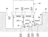
图2是表示图1中的要部I的放大剖视图。FIG. 2 is an enlarged cross-sectional view showing a main part I in FIG. 1 .
如图2所示,作为动叶片(叶片)50的前端部的叶端套筒51在径向上与分隔板外圈(结构体)11之间具有间隙而相对配置。叶端套筒51上形成有阶梯部52(52A~52C)。阶梯部52(52A~52C)具有台阶面53(53A~53C)而朝向分隔板外圈11突出。As shown in FIG. 2 , a
本实施方式中,叶端套筒51具有三个阶梯部52(52A~52C)。这三个阶梯部52A~52C中,朝向分隔板外圈11突出的径向的突出高度设置成从旋转轴向(以下记为轴向)上的蒸汽(流体)S的上游侧向下游侧逐渐变高。即,阶梯部52A~52C中,形成台阶的台阶面53(53A~53C)形成为朝向轴向上的蒸汽S的上游侧的朝前方式。In the present embodiment, the
在以下的说明中,只要未特别说明,就将未考虑涡流的轴向上的蒸汽S的流动的上游侧简单记载为“上游侧”。另外,将未考虑涡流的轴向上的蒸汽S的流动的下游侧简单记载为“下游侧”。In the following description, unless otherwise specified, the upstream side of the flow of the steam S in the axial direction without considering swirl is simply described as "upstream side". In addition, the downstream side of the flow of the steam S in the axial direction without considering the swirl is simply described as "downstream side".
分隔板外圈11上,在与叶端套筒51对应的部分上形成有环状槽(环状的凹部)11a。在该环状槽11a的内侧收容有叶端套筒51。On the partition plate
本实施方式中,环状槽11a的槽底面11b上的分隔板外圈11的内径在轴向上实质上相同。另外,在该槽底面11b上,设有朝向叶端套筒51而向径向的内侧延伸的三个密封凸片15(15A~15C)。In the present embodiment, the inner diameters of the partition plate
各个密封凸片15(15A~15C)一对一对应地设于各个阶梯部52(52A~52C)。密封凸片15设置成分别从槽底部11b朝向分隔板外圈11而沿径向延伸。在各个密封凸片与各个阶梯部52之间,沿径向形成有微小间隙H。关于各个微小间隙H(H1~H3)的尺寸,在考虑汽缸10和动叶片50的热引起的伸长量(热伸长量)和动叶片50的离心力引起的伸长量(离心伸长量)等的基础上,在汽缸10和动叶片50不致接触的安全范围内设定为最小的值。此外,本实施方式中,H1~H3均为相同尺寸。但是,也可以根据需要适宜改变这些尺寸。Each seal fin 15 (15A-15C) is provided in each step part 52 (52A-52C) in one-to-one correspondence. The sealing
通过以上构成,在叶端套筒51和分隔板外圈11之间,在环状槽11a的内侧形成有腔室C(C1~C3)。此外,对于一个阶梯部52(52A~52C)形成1个腔室C(C1~C3)。With the above configuration, the cavities C ( C1 to C3 ) are formed inside the
腔室C(C1~C3)在对应于各阶梯部52的密封凸片15与相对于该密封凸片15在上游侧相对的隔壁之间形成。The cavities C ( C1 to C3 ) are formed between the
第1级阶梯52A位于最上游侧。在对应于该阶梯52A的第1腔室C1中,环状槽11a的上游侧的内壁面54形成隔壁。The
因此,第1腔室C1在叶端套筒51与分隔板外圈11之间且在内壁面(隔壁)54与对应于第1级阶梯52A的密封凸片15A之间形成。Therefore, the first chamber C1 is formed between the
另外,在对应于第2级阶梯52B的第2腔室C2中,对应于位于上游侧的阶梯部52A的密封凸片15A形成隔壁。In addition, in the second chamber C2 corresponding to the second step 52B, the
因此,第2腔室C2在叶端套筒51与分隔板外圈11之间且在密封凸片(隔壁)15A与密封凸片15B之间形成。Therefore, the second chamber C2 is formed between the
同样,第3腔室C3在叶端套筒51与分隔板外圈11之间且在密封凸片(隔壁)15B与密封凸片15C之间形成。Similarly, the third chamber C3 is formed between the
在这种腔室C(C1~C3)中,将密封凸片15(15A~15C)的前端部与隔壁之间的轴向上的距离设为腔室宽度W(W1~W3)。即,腔室宽度W(W1~W3)是密封凸片15(15A~15C)的前端部、和与该密封凸片15的前端部同径上的隔壁之间的距离。In such chambers C ( C1 to C3 ), the distance in the axial direction between the front end portion of the seal fin 15 ( 15A to 15C) and the partition wall is defined as chamber width W ( W1 to W3 ). That is, the chamber width W ( W1 to W3 ) is the distance between the tip of the seal fin 15 ( 15A to 15C) and the partition wall on the same diameter as the tip of the
即,第1腔室C1中,将内壁面(隔壁)54与密封凸片15A之间的距离设为腔室宽度W1。第2腔室C2中,将密封凸片(隔壁)15A与密封凸片15B之间的距离设为腔室宽度W2。第3腔室C3中,将密封凸片(隔壁)15B与密封凸片15C之间的距离设为腔室宽度W3。此外,本实施方式中,W1~W3全部为相同尺寸。但是,也可以根据需要适宜改变这些尺寸。That is, in the first chamber C1, the distance between the inner wall surface (partition wall) 54 and the
另外,将所述密封凸片15和与其对应的各阶梯部52的上游侧的端缘部55之间的轴向上的距离、即密封凸片15和台阶面53的边缘55之间的轴向上的距离设为L(L1~L3)。此时,距离L中的至少1个满足以下的式(1)。In addition, the axial distance between the
0.7H≤L≤0.3W……(1)0.7H≤L≤0.3W...(1)
另外,该距离L中的至少1个也可以满足以下的式(2)。In addition, at least one of the distances L may satisfy the following formula (2).
1.25H≤L≤2.75H(其中,L≤0.3W)……(2)1.25H≤L≤2.75H (where L≤0.3W)...(2)
若满足上述的式(1)或式(2)的条件,则能够不依赖于涡轮的运转条件而得到本发明所期望的缩流效果。但是,即使在涡轮停止时满足式(1)或式(2)的条件,若在涡轮运转时不满足,则得不到所期望的效果。因此,式(1)或式(2)的条件必须在涡轮运转时得到满足。If the condition of the above-mentioned formula (1) or formula (2) is satisfied, the constriction effect desired by the present invention can be obtained independently of the operating conditions of the turbine. However, even if the condition of Expression (1) or Expression (2) is satisfied when the turbine is stopped, if it is not satisfied when the turbine is running, the desired effect cannot be obtained. Therefore, the conditions of formula (1) or formula (2) must be satisfied while the turbine is running.
此外,本实施方式中,H1~H3全部为相同尺寸。因此,H是代表H1~H3的数值。同样,W是代表W1~W3的数值。In addition, in this embodiment, all H1-H3 are the same size. Therefore, H is a numerical value representing H1 to H3. Similarly, W is a numerical value representing W1 to W3.
图1所示的轴承部60具备径向轴承装置61和推力轴承装置62,以可旋转的方式支撑轴体30。The bearing
接着,对具有上述的构成的蒸汽轮机1的动作,使用图1~图3进行说明。Next, the operation of the steam turbine 1 having the above-mentioned configuration will be described with reference to FIGS. 1 to 3 .
首先,形成图1所示的打开调整阀20(参照图1)的状态时,蒸汽S从未图示的锅炉流入汽缸10的内部空间。First, when the regulating valve 20 (refer to FIG. 1 ) is opened as shown in FIG. 1 , steam S flows into the internal space of the cylinder 10 from a boiler (not shown).
流入汽缸10的内部空间的蒸汽S依此通过各级中的环状静叶片组和环状动叶片组。此时,蒸汽S的压力能量由静叶片40变换成速度能量。经过静叶片40的蒸汽S的大部分流入与静叶片40同级的动叶片50之间。于是,蒸汽S的速度能量由动叶片50变换成旋转能量,使轴体30旋转。另一方面,蒸汽S的一部分(例如百分之几)成为从静叶片40流出后流入环状槽11a内的、所谓的泄漏蒸汽。The steam S flowing into the inner space of the cylinder 10 passes through the annular stationary blade set and the annular moving blade set in each stage in turn. At this time, the pressure energy of the steam S is converted into velocity energy by the
此处,如图3所示流入环状槽11a内的蒸汽S首先流入第1腔室C1。然后,蒸汽S冲击阶梯部52A的台阶面53A。并且,蒸汽S返回上游侧而产生主涡Y1。本例中,主涡Y1在图3的纸面上沿逆时针(第1方向)转动。Here, the steam S flowing into the
此时,特别是在阶梯部52A的端缘部(边缘)55,从所述主涡Y1剥离一部分的流动。由此,以向该主涡Y1的相反方向转动的方式产生剥离涡Y2。本例中,剥离涡Y2以在图3的纸面上沿顺时针(第2方向)转动的方式产生。该剥离涡Y2发挥减少穿过密封凸片15A和阶梯部52A之间的微小间隙H1的蒸汽S的泄漏流的缩流效果。At this time, especially at the edge portion (edge) 55 of the stepped
即,如图3所示形成剥离涡Y2时,剥离涡Y2在密封凸片15A的上游侧产生下降流。该下降流的速度矢量朝向径向的内侧(旋转轴侧)。该下降流在微小间隙H1的紧前处具有朝向径向的内侧的惯性力。因此,剥离涡Y2相对于穿过微小间隙H1的蒸汽S的泄漏流发挥向径向的内侧收缩的效果(缩流效果),蒸汽S的泄漏流量减小。That is, when the separation vortex Y2 is formed as shown in FIG. 3 , the separation vortex Y2 generates a downflow on the upstream side of the
例如,如图3所示假定剥离涡Y2形成圆形。于是,该剥离涡Y2的直径为微小间隙H1的2倍而其外周与密封凸片15A相接的情况下、即L1=2H1(L=2H)的情况下,该剥离涡Y2的下降流中的朝向径向的内侧的速度分量最大的位置与密封凸片15A的前端(内端缘)一致。因此该下降流更良好地通过微小间隙H1的紧前处,因此可认为对于蒸汽S的泄漏流的缩流效果为最大。For example, it is assumed that the separation vortex Y2 forms a circle as shown in FIG. 3 . Then, when the diameter of the separation vortex Y2 is twice the micro gap H1 and its outer periphery is in contact with the
基于存在像这样可充分得到缩流效果的条件的见解,本发明人进行了模拟。其结果是,本发明人决定密封凸片15(15A~15C)与台阶面53(53A~53C)的端缘部(边缘)55之间的轴向距离L(L1~L3),以满足上述的式(1)。或决定距离L(L1~L3),以满足式(2)。Based on the knowledge that there are conditions under which the vena contracta effect can be sufficiently obtained, the present inventors performed simulations. As a result, the present inventors determined the axial distance L (L1-L3) between the seal fins 15 (15A-15C) and the edge portion (edge) 55 of the stepped surface 53 (53A-53C) so as to satisfy the above-mentioned formula (1). Or determine the distance L (L1-L3) so as to satisfy the formula (2).
(模拟)(simulation)
此处,对于图2、图3所示的距离L、密封凸片15的微小间隙H、和腔室宽度W的相互之间的条件、与涡轮效率变化和泄漏量变化率之间的关系进行模拟。以下对其结果进行说明。Here, the relationship between the distance L shown in Fig. 2 and Fig. 3 , the small gap H of the
图4是表示模拟结果的图表。该图表中的横轴表示所述L的尺寸(长度),纵轴表示涡轮效率变化和泄漏量变化率。此外,对于涡轮效率变化和泄漏量变化率,表示一般性的阶梯凸片结构中的涡轮效率、相对于泄漏流量的大小。另外,该图表中,横轴、纵轴都不采用对数等特殊的刻度,而是采用一般的等差刻度。Fig. 4 is a graph showing simulation results. In this graph, the horizontal axis represents the dimension (length) of L, and the vertical axis represents the change in turbine efficiency and the rate of change in leakage amount. In addition, the change in turbine efficiency and the rate of change in leakage amount represent the size of the turbine efficiency in a general stepped fin structure relative to the leakage flow rate. In addition, in this chart, the horizontal axis and the vertical axis do not use special scales such as logarithms, but use general arithmetic scales.
由图4所示的结果可知,L优选处于满足以下的式(1)的范围,更优选处于满足式(2)的范围。From the results shown in FIG. 4 , L is preferably in a range satisfying the following formula (1), more preferably in a range satisfying formula (2).
0.7H≤L≤0.3W……(1)0.7H≤L≤0.3W...(1)
1.25H≤L≤2.75H(其中,L≤0.3W)……(2)1.25H≤L≤2.75H (where L≤0.3W)...(2)
即,图4所示的范围[1](L<0.7H)中,如图5所示在端缘部(边缘)55不生成剥离涡Y2。因此可知在密封凸片15的上游侧不形成下降流。因此,几乎得不到下降流产生的对于蒸汽S的泄漏流的缩流效果。其结果是,如图4所示泄漏量变化率变高(+侧),蒸汽S的泄漏流量增多。因此,涡轮效率变化变低(-侧),涡轮效率降低。That is, in the range [1] (L<0.7H) shown in FIG. 4 , no separation vortex Y2 is generated at the edge portion (edge) 55 as shown in FIG. 5 . Therefore, it can be seen that no downflow is formed on the upstream side of the
图4所示的范围[2](0.7H≤L≤0.3W)、即所述式(1)的范围内,如图6所示在端缘部(边缘)55生成剥离涡Y2。并且,可知,剥离涡Y2的下降流的较强部分(箭头D)位于密封凸片15的前端附近。因此,可充分得到下降流产生的对于蒸汽S的泄漏流的缩流效果。其结果是,如图4所示泄漏量变化率变低(-侧),蒸汽S的泄漏流量减少。因此,涡轮效率变化变高(+侧),涡轮效率增加。In the range [2] (0.7H≦L≦0.3W) shown in FIG. 4 , that is, in the range of the above-mentioned formula (1), a separation vortex Y2 is generated at the edge portion (edge) 55 as shown in FIG. 6 . Furthermore, it can be seen that the strong portion (arrow D) of the downflow of the separation vortex Y2 is located in the vicinity of the tip of the
此外,图4所示的范围[2a](0.7H≤L<1.25H)中,剥离涡Y2在端缘部(边缘)55生成。但是,可知,该情况下,生成的剥离涡Y2比较小。另外,可知,下降流最强的部分D位于与相比密封凸片15的前端靠径向上的内侧(旋转轴侧)的微小间隙H对应的位置。因此,如图4所示,可充分得到下降流产生的对于蒸汽S的泄漏流的缩流效果。但是,与后述的范围[2b]相比,对于蒸汽S的泄漏流的缩流效果较低。In addition, in the range [2a] (0.7H≦L<1.25H) shown in FIG. 4 , the separation vortex Y2 is generated at the edge portion (edge) 55 . However, it can be seen that in this case, the generated separation vortex Y2 is relatively small. In addition, it can be seen that the portion D where the downflow is strongest is located at a position corresponding to the small gap H on the inner side (rotation shaft side) in the radial direction than the front end of the
可知,图4所示的范围[2b](1.25H≤L≤2.75H)中,在端缘部(边缘)55生成较强的剥离涡Y2,该剥离涡Y2的下降流的最强的部分D与密封凸片15的前端大致一致。因此,如图4所示,下降流产生的对于蒸汽S的泄漏流的缩流效果最高。It can be seen that in the range [2b] (1.25H≤L≤2.75H) shown in FIG. 4, a strong separation vortex Y2 is generated at the edge portion (edge) 55, and the strongest part of the downward flow of the separation vortex Y2 is D substantially coincides with the front end of the sealing
可以说,尤其是如前所述,在L=2H的附近蒸汽S的泄漏流量最小,涡轮效率最大。It can be said that, especially as mentioned above, the leakage flow rate of the steam S is the smallest and the turbine efficiency is the largest near L=2H.
而且,可知,图4所示的范围[2c](2.75H<L≤0.3W)中,在端缘部(边缘)55生成的剥离涡Y2变大,下降流最强的部分D开始从密封凸片15的前端向径向的外侧分离。因此,如图4所示,可充分得到下降流产生的对于蒸汽S的泄漏流的缩流效果,但与范围[2b]相比缩流效果较低。Moreover, it can be seen that in the range [2c] (2.75H<L≤0.3W) shown in FIG. 4 , the separation vortex Y2 generated at the edge portion (edge) 55 becomes larger, and the part D where the downward flow is the strongest starts from the sealed The front end of the
另外,图4所示的范围[3](0.3W<L)中,如图7所示在端缘部(边缘)55生成的剥离涡Y2附着于环状槽11a的槽底面11b,产生大的涡。因此,剥离涡Y2的下降流最强的部分D向密封凸片15的高度的中间附近移动。因此,可知,在密封凸片15的前端部分不形成较强的下降流。因此,几乎得不到下降流产生的对于蒸汽S的泄漏流的缩流效果,如图4所示泄漏量变化率高(+侧),即蒸汽S的泄漏流量增多。因此,涡轮效率变化低(-侧),即,涡轮效率降低。In addition, in the range [3] (0.3W<L) shown in FIG. 4, the separation vortex Y2 generated at the edge portion (edge) 55 as shown in FIG. of the vortex. Therefore, the part D where the downflow of the separation vortex Y2 is the strongest moves to the vicinity of the middle of the height of the
由以上的模拟结果,本发明中将距离L设定为满足上述式(1)的范围。From the above simulation results, in the present invention, the distance L is set within a range satisfying the above-mentioned formula (1).
即,所述的各腔室C1~C3中,各阶梯部52A~52C和与其对应的密封凸片15A~15C之间的相互位置关系(微小间隙H、距离L)、进而各隔壁和各密封凸片15A~15C之间的相互位置关系(腔室宽度W)满足上述式(1)。因此,剥离涡Y2产生的缩流效果充分提高,蒸汽S的泄漏流量与现有技术相比显著减少。因此,具备这种密封结构的蒸汽轮机1中,蒸汽S的泄漏流量进一步减少,实现高性能化。That is, in each of the above-mentioned chambers C1 to C3, the mutual positional relationship between each of the stepped
另外,若微小间隙H、距离L和腔室宽度W满足式(2)的关系,则剥离涡Y2产生的缩流效果进一步提高,蒸汽S的泄漏流量进一步减少。因此,蒸汽轮机1进一步实现高性能化。In addition, if the small gap H, the distance L, and the chamber width W satisfy the relationship of formula (2), the contraction effect of the separation vortex Y2 will be further enhanced, and the leakage flow rate of the steam S will be further reduced. Therefore, the performance of the steam turbine 1 is further improved.
另外,该蒸汽轮机1中,形成3级阶梯部,形成3个腔室C。由此,各腔室C中,能够通过上述缩流效果减少蒸汽S的泄漏流量。因此,作为整体能够更充分地减少蒸汽S的泄漏流量。In addition, in this steam turbine 1, three steps are formed, and three chambers C are formed. Thereby, in each chamber C, the leakage flow rate of the steam S can be reduced by the above-mentioned vena contracta effect. Therefore, the leakage flow rate of the steam S can be reduced more sufficiently as a whole.
(第2实施方式)(second embodiment)
接着,说明本发明的第2实施方式的蒸汽轮机。Next, a steam turbine according to a second embodiment of the present invention will be described.
图8是用于说明第2实施方式的图。另外,图8是与表示图1中的要部I的放大剖视图即图2对应的图。FIG. 8 is a diagram for explaining the second embodiment. In addition, FIG. 8 is a diagram corresponding to FIG. 2 , which is an enlarged cross-sectional view showing main part I in FIG. 1 .
图8所示的第2实施方式与图2所示的第1实施方式在以下方面不同。即,第1实施方式中在作为动叶片(叶片)50的前端部的叶端套筒51上形成阶梯部52(52A~52C),在分隔板外圈(结构体)11上设有密封凸片15(15A~15C)。与此相对,第2实施方式中,在分隔板外圈(结构体)11上形成阶梯部52,在叶端套筒51上设有密封凸片15。The second embodiment shown in FIG. 8 differs from the first embodiment shown in FIG. 2 in the following points. That is, in the first embodiment, the stepped portion 52 ( 52A to 52C) is formed on the
即,该第2实施方式中,如图8所示,在形成于分隔板外圈(结构体)11的环状槽11a的槽底面11b上,形成2个阶梯部52。即,形成具有台阶面53D的阶梯部52D、具有台阶面53E的阶梯部52E作为2个阶梯部52。另一方面,在动叶片(叶片)50的前端部即叶端套筒51上,设有3个密封凸片15(15D~15F)。3个密封凸片15(15D~15F)以朝向形成于分隔板外圈11的环状槽11a的槽底面11b向径向的外侧延伸的方式设置。That is, in the second embodiment, as shown in FIG. 8 , two stepped
这些密封凸片15(15D~15F)中的上游侧的密封凸片15D与位于阶梯部52的上游侧的槽底面11b对应而延伸。另外,下游侧的密封凸片15E、15F分别与阶梯部52D、52E对应而沿径向延伸。此外,这些密封凸片15D~15F也在与对应的槽底面11b或阶梯部52之间形成微小间隙H。特别是密封凸片15E、15F在与对应的阶梯部52D、52E之间沿径向形成本发明的微小间隙H(H4、H5)。Among these seal fins 15 ( 15D to 15F ), the
该微小间隙H(H4、H5)的各尺寸与第1实施方式同样,在考虑汽缸10及动叶片50的热引起的伸长量、动叶片50的离心力引起的伸长量等的基础上,在汽缸10和动叶片50不致接触的安全范围内设定为最小的值。此外,本实施方式中,H4和H5为相同尺寸。但是,也可以根据需要适宜改变这些尺寸。The respective dimensions of the minute gaps H ( H4 , H5 ) are the same as those of the first embodiment, in consideration of the elongation of the cylinder 10 and the
基于这种构成,在叶端套筒51和分隔板外圈11之间形成有腔室C(C4、C5)。腔室C(C4、C5)在环状槽11a的内侧对每个阶梯部52与各阶梯部52对应而形成。Based on this configuration, the chamber C ( C4 , C5 ) is formed between the
腔室C(C4、C5)与第1实施方式同样,在与各阶梯部52对应的密封凸片15(15E、15F)与相对于这些密封凸片15在上游侧相对的隔壁之间形成。The cavities C ( C4 , C5 ) are formed between the seal fins 15 ( 15E, 15F) corresponding to the stepped
位于最上游侧的腔室C4与位于最上游侧的第1级阶梯52D对应。第1腔室C4中,通过位于上游侧的密封凸片15D形成隔壁。因此,在叶端套筒51与分隔板外圈11之间且密封凸片(隔壁)15D与密封凸片15E之间形成有第1腔室C4。The chamber C4 on the most upstream side corresponds to the
同样,在叶端套筒51与分隔板外圈11之间且密封凸片(隔壁)15E与密封凸片15F之间形成有第2腔室C5。Similarly, a second chamber C5 is formed between the
这种腔室C(C4、C5)中,将作为隔壁的密封凸片15和与阶梯部52对应的密封凸片15之间的轴向距离设为腔室宽度W(W4、W5)。并且,将所述密封凸片15和与其对应的各阶梯部52的上游侧的端缘部55之间的距离、即密封凸片15和台阶面53的边缘55之间的轴向距离设为L(L4、L5)。于是,该距离L中的至少1个满足上述的式(1)。另外,该距离L中的至少1个更优选满足上述的式(2)。In such chambers C ( C4 , C5 ), the axial distance between the
即,各腔室C4、C5中,各阶梯部52D、52E和与其对应的密封凸片15E、15F之间的相互位置关系即微小间隙H、距离L、以及隔壁和密封凸片15E、15F之间的相互位置关系即腔室宽度W满足上述的式(1)。因此,剥离涡Y2产生的对于蒸汽S的泄漏流的缩流效果充分变高,蒸汽S的泄漏流量与现有技术相比显著减少。因此,具备这种密封结构的蒸汽轮机中,蒸汽S的泄漏流量进一步减少,实现了高性能化。That is, in each chamber C4, C5, the mutual positional relationship between each stepped
另外,若处于满足式(2)的范围,则剥离涡Y2产生的缩流效果进一步提高,蒸汽S的泄漏流量进一步减少。因此,蒸汽轮机进一步实现高性能化。In addition, if the range satisfies the expression (2), the contraction effect by the separation vortex Y2 is further enhanced, and the leakage flow rate of the steam S is further reduced. Therefore, the performance of the steam turbine has been further improved.
另外,该蒸汽轮机中,形成2级阶梯部,形成2个腔室C。因此,在各腔室C中能够通过上述缩流效果减少蒸汽S的泄漏流量,作为整体能够充分减少蒸汽S的泄漏流量。In addition, in this steam turbine, two steps are formed, and two chambers C are formed. Therefore, in each chamber C, the leakage flow rate of the steam S can be reduced by the above-mentioned contraction effect, and the leakage flow rate of the steam S can be sufficiently reduced as a whole.
(第3实施方式)(third embodiment)
接着,说明本发明的第3实施方式的蒸汽轮机。Next, a steam turbine according to a third embodiment of the present invention will be described.
图9是用于说明第3实施方式的图,是表示图1中的要部J的放大剖视图。另外,图9是与图2对应的图。FIG. 9 is a diagram for explaining the third embodiment, and is an enlarged cross-sectional view showing a main part J in FIG. 1 . In addition, FIG. 9 is a diagram corresponding to FIG. 2 .
图9所示的第3实施方式与图2所示的第1实施方式在以下方面不同。即,第1实施方式中将本发明的“叶片”设为动叶片50,在作为其前端部的叶端套筒51上形成阶梯部52(52A~52C)。另外,第1实施方式中,将本发明的“结构体”设为分隔板外圈11,在此处设有密封凸片15(15A~15C)。与此相对,第3实施方式中,将本发明的“叶片”设为静叶片40,在其前端部上形成阶梯部52。另外,第3实施方式中,将本发明的“结构体”设为轴体(转子)30,在此处设有密封凸片15。The third embodiment shown in FIG. 9 differs from the first embodiment shown in FIG. 2 in the following points. That is, in the first embodiment, the "blade" of the present invention is referred to as a
即,该第3实施方式中,如图9所示在静叶片40的前端部上,设有沿周向延伸的枢毂套筒41。在该枢毂套筒41上,与第1实施方式的叶端套筒51同样,形成有3个阶梯部52(52F~52H)。这3个阶梯部52F~52H以距离静叶片40的径向的突出高度从上游侧朝向下游侧逐渐变高的方式设置。即,阶梯部52F~52H形成为形成台阶的台阶面53(53F~53H)朝向上游侧的朝前方式。That is, in the third embodiment, as shown in FIG. 9 , a
轴体30上,在与枢毂套筒41对应的部分即圆盘32、32(参照图1)之间形成有环状槽(环状的凹部)33。在该环状槽33的内侧收容有枢毂套筒41。本实施方式中,环状槽33的槽底面33a上的轴体30的外径在轴向上形成为大致相同。另外,在该槽底面33a上,设有朝向枢毂套筒41向径向的外侧延伸的3个密封凸片15(15G~15I)。On the
这些密封凸片15(15G~15I)与阶梯部52(52F~52H)一对一对应,以分别从槽底部33a朝向枢毂套筒41沿径向延伸的方式设置。在各个密封凸片15(15G~15I)与各个阶梯部52之间沿径向形成有微小间隙H。该微小间隙H(H6~H8)的各尺寸在考虑轴体30及静叶片40的热引起的伸长量、轴体30的离心力引起的伸长量等的基础上,在轴体30和静叶片40不致接触的安全范围内设定为最小的值。此外,本实施方式中,H6~H8也全部为相同尺寸。但是,也可以根据需要适宜改变这些尺寸。These seal fins 15 ( 15G to 15I ) correspond one-to-one to the stepped portions 52 ( 52F to 52H), and are provided so as to extend radially from the groove bottom 33 a toward the
基于这种构成,在枢毂套筒41与轴体30之间形成有腔室C(C6~C8)。腔室C(C6~C8)在环状槽33的内侧对每个阶梯部52与各阶梯部52对应而形成。Based on such a configuration, chambers C ( C6 to C8 ) are formed between the
腔室C(C6~C8)在与各阶梯部52对应的密封凸片15和相对于该密封凸片15在上游侧相对的隔壁之间形成。The cavities C ( C6 to C8 ) are formed between the
第1腔室C6与位于最上游侧的第1级阶梯52F对应。第1腔室C6中,通过环状槽33的上游侧的内壁面34形成隔壁。因此,在枢毂套筒41侧和轴体30之间且内壁面(隔壁)34和与第1级阶梯52F对应的密封凸片15G之间形成有第1腔室C6。The first chamber C6 corresponds to the
另外,第2腔室C7与第2级阶梯52G对应。第2腔室C7中,通过与位于轴向上游侧的阶梯部52F对应的密封凸片15G形成隔壁。因此,在枢毂套筒41与轴体30之间且密封凸片(隔壁)15G与密封凸片15H之间形成有第2腔室C7。同样,在枢毂套筒41与轴体30之间且密封凸片(隔壁)15H与密封凸片15I之间形成有第3腔室C8。In addition, the second chamber C7 corresponds to the
这种腔室C(C6~C8)中,将隔壁与密封凸片15之间的距离设为腔室宽度W。并且,将各密封凸片15与各阶梯部52的上游侧的端缘部之间的轴向距离、即密封凸片15与台阶面53的边缘55之间的轴向上的距离设为L(L6~L8)。于是,该距离L中的至少1个满足上述的式(1)。另外,更优选该距离L中的至少1个满足上述的式(2)。In such cavities C ( C6 to C8 ), the distance between the partition wall and the
即,各阶梯部52F~52H和与其对应的密封凸片15G~15I之间的相互位置关系即微小间隙H、距离L、以及隔壁和密封凸片15之间的相互位置关系即腔室宽度W满足上述的式(1)。因此,剥离涡Y2产生的对于蒸汽S的泄漏流的缩流效果充分提高,蒸汽S的泄漏流量与现有技术相比显著减少。因此,具备这种密封结构的蒸汽轮机中,蒸汽S的泄漏流量进一步减少,实现了高性能化。That is, the mutual positional relationship between each
另外,若处于满足式(2)的范围,则剥离涡Y2产生的对于蒸汽S的泄漏流的缩流效果进一步提高,蒸汽S的泄漏流量进一步减少。因此,蒸汽轮机进一步实现了高性能化。In addition, in the range satisfying the expression (2), the shrinkage effect of the separation vortex Y2 on the leakage flow of the steam S is further enhanced, and the leakage flow rate of the steam S is further reduced. Therefore, the performance of the steam turbine has been further improved.
另外,该蒸汽轮机中,形成3级阶梯部,形成3个腔室C。因此,能够在各腔室C中通过上述缩流效果减少蒸汽S的泄漏流量,作为整体能够更充分地减少蒸汽S的泄漏流量。In addition, in this steam turbine, three steps are formed, and three chambers C are formed. Therefore, the leakage flow rate of the steam S can be reduced by the above-mentioned contraction effect in each chamber C, and the leakage flow rate of the steam S can be reduced more sufficiently as a whole.
(第4实施方式)(fourth embodiment)
接着,说明本发明的第4实施方式的蒸汽轮机。Next, a steam turbine according to a fourth embodiment of the present invention will be described.
图10是用于说明第4实施方式的图,是表示图1中的要部J的放大剖视图。另外,图10是与图2对应的图。FIG. 10 is a diagram for explaining the fourth embodiment, and is an enlarged cross-sectional view showing a main part J in FIG. 1 . In addition, FIG. 10 is a diagram corresponding to FIG. 2 .
图10所示的第4实施方式与图9所示的第3实施方式不同的是如下方面。即,第3实施方式中,在作为静叶片(叶片)40的前端部的枢毂套筒41上形成阶梯部52(52I、52J),在轴体(结构体)30上设有密封凸片15(15J~15L)。与此相对,第4实施方式中,在轴体(结构体)30上形成阶梯部52,在枢毂套筒41上设有密封凸片15。The fourth embodiment shown in FIG. 10 differs from the third embodiment shown in FIG. 9 in the following points. That is, in the third embodiment, the stepped portion 52 ( 52I, 52J) is formed on the
即,该第4实施方式中,如图10所示,在形成于轴体(结构体)30上的环状槽33的槽底面33a上,形成2个阶梯部52。更具体地说,这2个阶梯部52是具有台阶面53I的阶梯部52I和具有台阶面53J的阶梯部52J。另一方面,在静叶片(叶片)40的前端部即枢毂套筒41上,设有朝向轴体30的槽底面33a向径向的内侧延伸的3个密封凸片15(15J~15L)。That is, in the fourth embodiment, as shown in FIG. 10 , two stepped
这些密封凸片15(15J~15L)中的上游侧的密封凸片15J与位于阶梯部52的上游侧的槽底面33a对应而沿径向延伸。下游侧的密封凸片15K、15L分别与阶梯部52I、52J对应而沿径向延伸。此外,这些密封凸片15J~15L也在与对应的槽底面33a或阶梯部52之间形成微小间隙H。特别是密封凸片15K、15L在与对应的阶梯部52I、52J之间沿径向形成本发明的微小间隙H(H9、H10)。Among these seal fins 15 ( 15J to 15L), the
该微小间隙H(H9、H10)的各尺寸与第3实施方式同样,在考虑轴体30及静叶片40的热引起的伸长量、轴体30的离心力引起的伸长量等的基础上,在轴体30和静叶片40不致接触的安全范围内设定为最小的值。此外,本实施方式中,H9和H10也为相同尺寸。但是,也可以根据需要适宜改变这些尺寸。The dimensions of the minute gaps H ( H9 , H10 ) are the same as those of the third embodiment, taking into consideration the amount of elongation of the
基于这种构成,在枢毂套筒41和轴体30之间形成腔室C(C9、C10)。腔室C(C9、C10)在环状槽33的内侧对每个阶梯部52与各阶梯部对应而形成。Based on this configuration, the chamber C ( C9 , C10 ) is formed between the
腔室C(C9、C10)与第3实施方式同样,在与各阶梯部52对应的密封凸片15(15K、15L)和相对于这些密封凸片15在上游侧相对的隔壁之间形成。The cavities C ( C9 , C10 ) are formed between the seal fins 15 ( 15K, 15L) corresponding to the stepped
第1腔室C9对应于位于最上游侧的第1级阶梯52I。第1腔室C9中,由位于上游侧的密封凸片15J形成隔壁。因此,在枢毂套筒41与轴体30之间且密封凸片(隔壁)15J与密封凸片15K之间形成第1腔室C9。The first chamber C9 corresponds to the first step 52I located on the most upstream side. In the first chamber C9, a partition wall is formed by the
同样,在枢毂套筒41与轴体30之间且密封凸片(隔壁)15K与密封凸片15L之间形成第2腔室C10。Similarly, the second chamber C10 is formed between the
在这种腔室C(C9、C10)中,将作为隔壁的密封凸片15与对应于阶梯部52的密封凸片15之间的距离设为腔室宽度W。并且,将密封凸片15和与其对应的各阶梯部52的上游侧的端缘部55之间的轴向距离、即密封凸片15和台阶面53的边缘55之间的轴向距离设为L(L9、L10)。于是,该距离L中的至少1个满足上述的式(1)。另外,更优选该距离L中的至少1个满足上述的式(2)。In such chambers C ( C9 , C10 ), the distance between the
即,各阶梯部52I、52J和与其对应的密封凸片15K、15L之间的相互位置关系即微小间隙H、距离L、以及隔壁和密封凸片15之间的相互位置关系即腔室宽度W满足上述的式(1)。因此,剥离涡Y2产生的对于蒸汽S的泄漏流的缩流效果充分提高,蒸汽S的泄漏流量与现有技术相比显著减少。因此,具备这种密封结构的蒸汽轮机中,蒸汽S的泄漏流量进一步减少,实现了高性能化。That is, the mutual positional relationship between each
另外,若处于满足式(2)的范围,则剥离涡Y2产生的缩流效果进一步提高,蒸汽S的泄漏流量进一步减少。因此,蒸汽轮机进一步实现高性能化。In addition, if the range satisfies the expression (2), the contraction effect by the separation vortex Y2 is further enhanced, and the leakage flow rate of the steam S is further reduced. Therefore, the performance of the steam turbine has been further improved.
另外,该蒸汽轮机中,形成2级阶梯部,形成2个腔室C。因此,在各腔室C中通过上述缩流效果能够减少蒸汽S的泄漏流量,作为整体能够进一步充分减少蒸汽S的泄漏流量。In addition, in this steam turbine, two steps are formed, and two chambers C are formed. Therefore, in each chamber C, the leakage flow rate of the steam S can be reduced by the above-mentioned constriction effect, and the leakage flow rate of the steam S can be further sufficiently reduced as a whole.
以上,说明了本发明的优选实施方式,但本发明不限定于上述的实施方式。在不脱离本发明的主旨的范围内,能够进行构成的添加、省略、置换、及其他的变更。本发明不由上述说明限定,而仅由附加的权利要求的范围限定。Preferred embodiments of the present invention have been described above, but the present invention is not limited to the above-described embodiments. Additions, omissions, substitutions, and other changes can be made without departing from the scope of the present invention. The present invention is not limited by the foregoing description, but only by the scope of the appended claims.
上述实施方式中所示的动作步骤、或各构成构件的各种形状及组合等是一例,在不脱离本发明的主旨的范围内,能够基于设计要求等进行各种变更。The operation steps shown in the above-mentioned embodiments, and various shapes and combinations of constituent members are examples, and various changes can be made based on design requirements and the like without departing from the gist of the present invention.
例如在上述的实施方式中,关于设有密封凸片15的构件,不是形成为阶梯形状,而是形成为平面形状。但是,关于设有密封凸片15的构件,也可以与相对的阶梯部52的形状一致而形成为阶梯形状,也可以形成倾斜面或曲面。For example, in the above-described embodiment, the member provided with the
另外,上述的第1实施方式、第2实施方式中,将设于汽缸10的分隔板外圈11形成为结构体。但是,也可以不设置这种分隔板外圈11,而将汽缸10自身作为本发明的结构体。即,该结构体为环绕动叶片50而形成流体通过动叶片之间的流路的构件即可。In addition, in the first embodiment and the second embodiment described above, the partition plate
另外,上述的实施方式中,设有多个阶梯部52,由此也形成多个腔室C。但是,关于这些阶梯部52及与其对应的腔室C的数量是任意的,也可以是1个、3个、或4个以上。In addition, in the above-mentioned embodiment, a plurality of stepped
另外,不一定需要如所述实施方式那样,使密封凸片15和阶梯部52一对一对应。另外,不一定需要使阶梯部52比密封凸片15少1个。关于这些数量可任意设计。In addition, it is not necessarily necessary to make one-to-one correspondence between the
另外,上述的实施方式中,对最末级的动叶片50或静叶片40适用本发明,但也可以对其他级动叶片50或静叶片40适用本发明。In addition, in the above-mentioned embodiment, the present invention is applied to the
另外,上述的实施方式中,将本发明适用于复水式的蒸汽轮机。但是,本发明也可以适用于其他类型的蒸汽轮机,例如二级抽气涡轮、抽气涡轮、混气涡轮等涡轮类型。In addition, in the above-mentioned embodiments, the present invention is applied to a rehydration type steam turbine. However, the present invention can also be applied to other types of steam turbines, such as two-stage extraction turbines, extraction turbines, gas-mixing turbines and other turbine types.
而且,上述的实施方式中,将本发明适用于蒸汽轮机。但是,本发明也能够适用于气体涡轮。而且,本发明可适用于具有旋转叶片的所有旋转机械。Furthermore, in the above-described embodiments, the present invention is applied to a steam turbine. However, the invention can also be applied to gas turbines. Furthermore, the invention is applicable to all rotating machines having rotating blades.
工业实用性Industrial Applicability
设在密封凸片与阶梯部之间形成的微小间隙为H。另外,将形成腔室的隔壁与密封凸片之间的距离设为腔室宽度W。另外,将密封凸片与阶梯部的上游侧的端缘部之间的距离设为L。此时,距离L中的至少1个满足以下的式(1)。Let H be the minute gap formed between the seal fin and the stepped portion. In addition, let the distance between the partition wall which forms a cavity, and a sealing fin be cavity width W. In addition, let L be the distance between a seal fin and the edge part of the upstream side of a step part. At this time, at least one of the distances L satisfies the following formula (1).
0.7H≤L≤0.3W……(1)0.7H≤L≤0.3W...(1)
由此,能够提供使流体的泄漏流量相比现有技术减少的高性能涡轮。Thereby, it is possible to provide a high-performance turbine in which the leakage flow rate of the fluid is reduced compared with the prior art.
标号说明Label description
1…蒸汽轮机(涡轮)、10…汽缸、11…分隔板外圈(结构体)、11a…环状槽(环状的凹部)、11b…槽底面、15(15A~15L)…密封凸片、30…轴体(结构体)、33…环状槽(环状的凹部)、33a…槽底面、40…静叶片(叶片)、41…枢毂套筒、50…动叶片(叶片)、51…叶端套筒、52(52A~52J)…阶梯部、53(53A~53J)…台阶面、54…内壁面、55…端缘部(边缘)、C(C1~C10)…腔室、H(H1~H10)…微小间隙、W(W1~W10)…腔室宽度、L(L1~L10)…距离、S…蒸汽、Y1…主涡、Y2…剥离涡1...Steam turbine (turbine), 10...Cylinder, 11...Partition plate outer ring (structure), 11a...Annular groove (annular recess), 11b...Groove bottom surface, 15 (15A~15L)...Seal convex Sheet, 30...shaft body (structure), 33...annular groove (annular recess), 33a...groove bottom surface, 40...stationary blade (blade), 41...hub sleeve, 50...moving blade (blade) , 51...Blade end sleeve, 52(52A~52J)...Step part, 53(53A~53J)...Step surface, 54...Inner wall surface, 55...End edge (edge), C(C1~C10)...Cavity Chamber, H(H1~H10)…micro gap, W(W1~W10)…chamber width, L(L1~L10)…distance, S…steam, Y1…main vortex, Y2…stripping vortex
Claims (7)
Applications Claiming Priority (3)
| Application Number | Priority Date | Filing Date | Title |
|---|---|---|---|
| JP2009235430A JP2011080452A (en) | 2009-10-09 | 2009-10-09 | Turbine |
| JP2009-235430 | 2009-10-09 | ||
| PCT/JP2010/067350 WO2011043286A1 (en) | 2009-10-09 | 2010-10-04 | Turbine |
Publications (2)
| Publication Number | Publication Date |
|---|---|
| CN102449268A true CN102449268A (en) | 2012-05-09 |
| CN102449268B CN102449268B (en) | 2015-12-16 |
Family
ID=43856741
Family Applications (1)
| Application Number | Title | Priority Date | Filing Date |
|---|---|---|---|
| CN201080023193.2A Active CN102449268B (en) | 2009-10-09 | 2010-10-04 | turbine |
Country Status (6)
| Country | Link |
|---|---|
| US (1) | US8784046B2 (en) |
| EP (1) | EP2487332B1 (en) |
| JP (1) | JP2011080452A (en) |
| KR (1) | KR101279191B1 (en) |
| CN (1) | CN102449268B (en) |
| WO (1) | WO2011043286A1 (en) |
Cited By (4)
| Publication number | Priority date | Publication date | Assignee | Title |
|---|---|---|---|---|
| CN104508253A (en) * | 2012-08-23 | 2015-04-08 | 三菱日立电力系统株式会社 | Rotary machine |
| CN104903547A (en) * | 2012-12-13 | 2015-09-09 | 三菱日立电力系统株式会社 | Rotary fluid machine |
| CN107208493A (en) * | 2015-01-27 | 2017-09-26 | 三菱日立电力系统株式会社 | Turbine |
| CN114776389A (en) * | 2022-03-16 | 2022-07-22 | 北京航空航天大学 | Shrouded turbine with flange plate step casing |
Families Citing this family (22)
| Publication number | Priority date | Publication date | Assignee | Title |
|---|---|---|---|---|
| JP5484990B2 (en) | 2010-03-30 | 2014-05-07 | 三菱重工業株式会社 | Turbine |
| US8834107B2 (en) * | 2010-09-27 | 2014-09-16 | General Electric Company | Turbine blade tip shroud for use with a tip clearance control system |
| JP5709447B2 (en) | 2010-09-28 | 2015-04-30 | 三菱日立パワーシステムズ株式会社 | Turbine |
| JP5517910B2 (en) | 2010-12-22 | 2014-06-11 | 三菱重工業株式会社 | Turbine and seal structure |
| JP5518022B2 (en) * | 2011-09-20 | 2014-06-11 | 三菱重工業株式会社 | Turbine |
| JP5783570B2 (en) * | 2011-11-28 | 2015-09-24 | 三菱日立パワーシステムズ株式会社 | Turbine |
| JP5518032B2 (en) * | 2011-12-13 | 2014-06-11 | 三菱重工業株式会社 | Turbine and seal structure |
| JP6197985B2 (en) * | 2012-02-29 | 2017-09-20 | 三菱日立パワーシステムズ株式会社 | Seal structure and turbine device provided with the same |
| JP5936403B2 (en) * | 2012-03-22 | 2016-06-22 | 三菱日立パワーシステムズ株式会社 | Turbine |
| JP5916458B2 (en) | 2012-03-23 | 2016-05-11 | 三菱日立パワーシステムズ株式会社 | Turbine |
| JP5972374B2 (en) * | 2012-07-11 | 2016-08-17 | 三菱日立パワーシステムズ株式会社 | Axial fluid machine |
| JP5936515B2 (en) | 2012-10-18 | 2016-06-22 | 三菱日立パワーシステムズ株式会社 | Rotating machine |
| JP6296649B2 (en) | 2014-03-04 | 2018-03-20 | 三菱日立パワーシステムズ株式会社 | Seal structure and rotating machine |
| JP6530918B2 (en) | 2015-01-22 | 2019-06-12 | 三菱日立パワーシステムズ株式会社 | Turbine |
| CN107438717B (en) | 2015-04-15 | 2021-10-08 | 罗伯特·博世有限公司 | Free Tip Axial Fan Assembly |
| CN106285790B (en) * | 2015-06-05 | 2019-10-25 | 上海汽轮机厂有限公司 | Gland seal structure |
| JP6209200B2 (en) | 2015-12-09 | 2017-10-04 | 三菱日立パワーシステムズ株式会社 | Step seal, seal structure, turbomachine, and step seal manufacturing method |
| JP2017145813A (en) | 2016-02-19 | 2017-08-24 | 三菱日立パワーシステムズ株式会社 | Rotating machine |
| JP6706585B2 (en) | 2017-02-23 | 2020-06-10 | 三菱重工業株式会社 | Axial rotating machine |
| JP6917162B2 (en) * | 2017-02-28 | 2021-08-11 | 三菱パワー株式会社 | Blades, rotor units, and rotating machines |
| JP6856748B2 (en) * | 2017-06-12 | 2021-04-14 | 三菱パワー株式会社 | Axial rotating machine |
| DE102024115122A1 (en) * | 2024-05-29 | 2025-12-04 | Ebm-Papst Mulfingen Gmbh & Co. Kg | Non-contact dynamic seal for sealing a radial gap |
Citations (7)
| Publication number | Priority date | Publication date | Assignee | Title |
|---|---|---|---|---|
| JPS5338806A (en) * | 1976-09-22 | 1978-04-10 | Hitachi Ltd | Seal device for nose part of movable vane |
| JPH11200810A (en) * | 1998-01-09 | 1999-07-27 | Mitsubishi Heavy Ind Ltd | Labyrinth seal mechanism |
| JP2002228014A (en) * | 2001-02-05 | 2002-08-14 | Mitsubishi Heavy Ind Ltd | Labyrinth seal |
| US20050100439A1 (en) * | 2003-09-09 | 2005-05-12 | Alstom Technology Ltd | Turbomachine |
| CN2725533Y (en) * | 2004-07-28 | 2005-09-14 | 上海汽轮机有限公司 | High power steam turbine low pressure self crown carried long blade stepped surrounding belt |
| JP2006291967A (en) * | 2006-05-29 | 2006-10-26 | Toshiba Corp | Axial flow turbine |
| JP2009047043A (en) * | 2007-08-17 | 2009-03-05 | Mitsubishi Heavy Ind Ltd | Axial flow turbine |
Family Cites Families (18)
| Publication number | Priority date | Publication date | Assignee | Title |
|---|---|---|---|---|
| DE2462465B2 (en) * | 1974-03-21 | 1979-07-12 | Maschinenfabrik Augsburg-Nuernberg Ag, 8500 Nuernberg | Device for dynamic stabilization of the rotor of a high-speed compressor |
| FR2374766A1 (en) | 1976-12-20 | 1978-07-13 | Lincoln Electric Co | Ignition circuit for IC engine driving self-excited generator - has field winding core with remanence insufficient for self-excitation when engine stops |
| JPS53104803U (en) * | 1977-01-31 | 1978-08-23 | ||
| JPS5951104A (en) | 1982-09-17 | 1984-03-24 | Hitachi Ltd | Internal structure of turbine stage |
| JPS6123804A (en) | 1984-07-10 | 1986-02-01 | Hitachi Ltd | Turbine paragraph structure |
| JPS61134501A (en) | 1984-12-06 | 1986-06-21 | 株式会社東芝 | Integral once-through type steam generator |
| JPS6361501A (en) | 1986-09-01 | 1988-03-17 | Matsushita Electric Ind Co Ltd | Plane antenna jointed with frequency converter into one body |
| JPH0435601A (en) | 1990-05-31 | 1992-02-06 | Kunimitsu Masuda | Manufacture of ornamental body for accessory |
| JPH04350302A (en) | 1991-05-28 | 1992-12-04 | Hitachi Ltd | turbine stage structure |
| JPH0913905A (en) | 1995-06-30 | 1997-01-14 | Mitsubishi Heavy Ind Ltd | Turbine |
| JPH10311205A (en) | 1997-05-14 | 1998-11-24 | Toshiba Corp | Axial turbine |
| EP0903468B1 (en) | 1997-09-19 | 2003-08-20 | ALSTOM (Switzerland) Ltd | Gap sealing device |
| JPH11148307A (en) | 1997-11-17 | 1999-06-02 | Hitachi Ltd | Turbine seal structure |
| JP2004332616A (en) | 2003-05-07 | 2004-11-25 | Toshiba Corp | Axial turbomachine |
| US20090072487A1 (en) | 2007-09-18 | 2009-03-19 | Honeywell International, Inc. | Notched tooth labyrinth seals and methods of manufacture |
| JP5347295B2 (en) | 2008-03-26 | 2013-11-20 | Jfeスチール株式会社 | Zinc-based plated steel sheet and method for producing the same |
| JP2010216321A (en) | 2009-03-16 | 2010-09-30 | Hitachi Ltd | Moving blade of steam turbine, and steam turbine using the same |
| JP5484990B2 (en) | 2010-03-30 | 2014-05-07 | 三菱重工業株式会社 | Turbine |
-
2009
- 2009-10-09 JP JP2009235430A patent/JP2011080452A/en not_active Withdrawn
-
2010
- 2010-10-04 KR KR1020117028488A patent/KR101279191B1/en active Active
- 2010-10-04 EP EP10821956.9A patent/EP2487332B1/en active Active
- 2010-10-04 US US13/386,084 patent/US8784046B2/en active Active
- 2010-10-04 CN CN201080023193.2A patent/CN102449268B/en active Active
- 2010-10-04 WO PCT/JP2010/067350 patent/WO2011043286A1/en not_active Ceased
Patent Citations (7)
| Publication number | Priority date | Publication date | Assignee | Title |
|---|---|---|---|---|
| JPS5338806A (en) * | 1976-09-22 | 1978-04-10 | Hitachi Ltd | Seal device for nose part of movable vane |
| JPH11200810A (en) * | 1998-01-09 | 1999-07-27 | Mitsubishi Heavy Ind Ltd | Labyrinth seal mechanism |
| JP2002228014A (en) * | 2001-02-05 | 2002-08-14 | Mitsubishi Heavy Ind Ltd | Labyrinth seal |
| US20050100439A1 (en) * | 2003-09-09 | 2005-05-12 | Alstom Technology Ltd | Turbomachine |
| CN2725533Y (en) * | 2004-07-28 | 2005-09-14 | 上海汽轮机有限公司 | High power steam turbine low pressure self crown carried long blade stepped surrounding belt |
| JP2006291967A (en) * | 2006-05-29 | 2006-10-26 | Toshiba Corp | Axial flow turbine |
| JP2009047043A (en) * | 2007-08-17 | 2009-03-05 | Mitsubishi Heavy Ind Ltd | Axial flow turbine |
Cited By (9)
| Publication number | Priority date | Publication date | Assignee | Title |
|---|---|---|---|---|
| CN104508253A (en) * | 2012-08-23 | 2015-04-08 | 三菱日立电力系统株式会社 | Rotary machine |
| US9879786B2 (en) | 2012-08-23 | 2018-01-30 | Mitsubishi Hitachi Power Systems, Ltd. | Rotary machine |
| CN104508253B (en) * | 2012-08-23 | 2019-03-19 | 三菱日立电力系统株式会社 | Rotary machine |
| CN104903547A (en) * | 2012-12-13 | 2015-09-09 | 三菱日立电力系统株式会社 | Rotary fluid machine |
| CN104903547B (en) * | 2012-12-13 | 2016-09-21 | 三菱日立电力系统株式会社 | Rotary fluid machine |
| CN107208493A (en) * | 2015-01-27 | 2017-09-26 | 三菱日立电力系统株式会社 | Turbine |
| CN107208493B (en) * | 2015-01-27 | 2019-06-28 | 三菱日立电力系统株式会社 | turbine |
| CN114776389A (en) * | 2022-03-16 | 2022-07-22 | 北京航空航天大学 | Shrouded turbine with flange plate step casing |
| CN114776389B (en) * | 2022-03-16 | 2024-03-12 | 北京航空航天大学 | Shrouded turbine with rim plate step casing |
Also Published As
| Publication number | Publication date |
|---|---|
| EP2487332A4 (en) | 2017-12-20 |
| US20120121393A1 (en) | 2012-05-17 |
| US8784046B2 (en) | 2014-07-22 |
| EP2487332B1 (en) | 2020-03-11 |
| KR101279191B1 (en) | 2013-06-27 |
| JP2011080452A (en) | 2011-04-21 |
| EP2487332A1 (en) | 2012-08-15 |
| CN102449268B (en) | 2015-12-16 |
| KR20120010272A (en) | 2012-02-02 |
| WO2011043286A1 (en) | 2011-04-14 |
Similar Documents
| Publication | Publication Date | Title |
|---|---|---|
| CN102449268A (en) | turbine | |
| CN102695849B (en) | Turbine | |
| CN102834589B (en) | Turbine | |
| CN102959184B (en) | Turbine | |
| EP3018297B1 (en) | Sealing device and turbo machine | |
| CN104204419B (en) | turbine | |
| US9353640B2 (en) | Turbine | |
| CN103717842B (en) | turbine | |
| CN104736906B (en) | rotating machinery | |
| WO2015133313A1 (en) | Seal structure and rotary machine | |
| JP6518526B2 (en) | Axial flow turbine | |
| US11131201B2 (en) | Rotor blade, rotor unit, and rotating machine | |
| CN111622811B (en) | Axial flow turbine | |
| CN111622812A (en) | Axial flow steam turbine |
Legal Events
| Date | Code | Title | Description |
|---|---|---|---|
| C06 | Publication | ||
| PB01 | Publication | ||
| C10 | Entry into substantive examination | ||
| SE01 | Entry into force of request for substantive examination | ||
| C14 | Grant of patent or utility model | ||
| GR01 | Patent grant |