CN102413755A - Endoscope device - Google Patents
Endoscope device Download PDFInfo
- Publication number
- CN102413755A CN102413755A CN2010800195796A CN201080019579A CN102413755A CN 102413755 A CN102413755 A CN 102413755A CN 2010800195796 A CN2010800195796 A CN 2010800195796A CN 201080019579 A CN201080019579 A CN 201080019579A CN 102413755 A CN102413755 A CN 102413755A
- Authority
- CN
- China
- Prior art keywords
- treatment instrument
- endoscope
- main body
- direction side
- treatment
- Prior art date
- Legal status (The legal status is an assumption and is not a legal conclusion. Google has not performed a legal analysis and makes no representation as to the accuracy of the status listed.)
- Granted
Links
Images


Classifications
-
- A—HUMAN NECESSITIES
- A61—MEDICAL OR VETERINARY SCIENCE; HYGIENE
- A61B—DIAGNOSIS; SURGERY; IDENTIFICATION
- A61B1/00—Instruments for performing medical examinations of the interior of cavities or tubes of the body by visual or photographical inspection, e.g. endoscopes; Illuminating arrangements therefor
- A61B1/012—Instruments for performing medical examinations of the interior of cavities or tubes of the body by visual or photographical inspection, e.g. endoscopes; Illuminating arrangements therefor characterised by internal passages or accessories therefor
- A61B1/018—Instruments for performing medical examinations of the interior of cavities or tubes of the body by visual or photographical inspection, e.g. endoscopes; Illuminating arrangements therefor characterised by internal passages or accessories therefor for receiving instruments
-
- A—HUMAN NECESSITIES
- A61—MEDICAL OR VETERINARY SCIENCE; HYGIENE
- A61B—DIAGNOSIS; SURGERY; IDENTIFICATION
- A61B17/00—Surgical instruments, devices or methods
- A61B17/28—Surgical forceps
- A61B17/29—Forceps for use in minimally invasive surgery
-
- A—HUMAN NECESSITIES
- A61—MEDICAL OR VETERINARY SCIENCE; HYGIENE
- A61B—DIAGNOSIS; SURGERY; IDENTIFICATION
- A61B17/00—Surgical instruments, devices or methods
- A61B17/00234—Surgical instruments, devices or methods for minimally invasive surgery
- A61B2017/00292—Surgical instruments, devices or methods for minimally invasive surgery mounted on or guided by flexible, e.g. catheter-like, means
- A61B2017/00296—Surgical instruments, devices or methods for minimally invasive surgery mounted on or guided by flexible, e.g. catheter-like, means mounted on an endoscope
-
- A—HUMAN NECESSITIES
- A61—MEDICAL OR VETERINARY SCIENCE; HYGIENE
- A61B—DIAGNOSIS; SURGERY; IDENTIFICATION
- A61B17/00—Surgical instruments, devices or methods
- A61B17/28—Surgical forceps
- A61B17/29—Forceps for use in minimally invasive surgery
- A61B2017/2926—Details of heads or jaws
- A61B2017/2927—Details of heads or jaws the angular position of the head being adjustable with respect to the shaft
- A61B2017/2929—Details of heads or jaws the angular position of the head being adjustable with respect to the shaft with a head rotatable about the longitudinal axis of the shaft
- A61B2017/293—Details of heads or jaws the angular position of the head being adjustable with respect to the shaft with a head rotatable about the longitudinal axis of the shaft with means preventing relative rotation between the shaft and the actuating rod
Landscapes
- Health & Medical Sciences (AREA)
- Life Sciences & Earth Sciences (AREA)
- Surgery (AREA)
- General Health & Medical Sciences (AREA)
- Public Health (AREA)
- Veterinary Medicine (AREA)
- Nuclear Medicine, Radiotherapy & Molecular Imaging (AREA)
- Animal Behavior & Ethology (AREA)
- Molecular Biology (AREA)
- Engineering & Computer Science (AREA)
- Biomedical Technology (AREA)
- Heart & Thoracic Surgery (AREA)
- Medical Informatics (AREA)
- Biophysics (AREA)
- Radiology & Medical Imaging (AREA)
- Physics & Mathematics (AREA)
- Pathology (AREA)
- Optics & Photonics (AREA)
- Ophthalmology & Optometry (AREA)
- Endoscopes (AREA)
- Surgical Instruments (AREA)
Abstract
Description
技术领域 technical field
本发明涉及内窥镜装置,该内窥镜装置包括:内窥镜;和机械手、钳子等处置器具,其贯穿插入于处置器具贯穿插入通道,该处置器具贯穿插入通道设置于内窥镜或与内窥镜分开的管状体。The present invention relates to an endoscope device. The endoscope device includes: an endoscope; and treatment instruments such as manipulators and forceps, which are inserted into the treatment instrument insertion channel. The divided tubular body of an endoscope.
背景技术 Background technique
一般情况下,应用有以下的内窥镜装置:将内窥镜插入体腔内,并经由内窥镜或与内窥镜分开的管状体的处置器具贯穿插入通道使机械手、钳子等处置器具从内窥镜或管状体的末端突出。在内窥镜装置中,在通过内窥镜进行观察的情况下,处置器具在体腔内进行处置。Generally, the following endoscopic devices are used: the endoscope is inserted into the body cavity, and the endoscope or the treatment instrument of the tubular body separated from the endoscope is inserted through the insertion channel so that the treatment instruments such as manipulators and forceps are inserted from the inside. The end of the speculum or tubular body protrudes. In the endoscope apparatus, the treatment instrument performs treatment in the body cavity when observing with the endoscope.
作为贯穿插入于内窥镜或管状体的处置器具贯穿插入通道中的处置器具,在专利文献1中,公开有利用高频电极把持患处进行处置的高频处置器具。所述高频处置器具包括:插入体腔内的插入部;和设置成比插入部更靠近基端方向侧的操作部。插入部包括:设置有高频电极的末端处置部;和处置器具主体,该处置器具主体设置成比末端处置部更靠近基端方向侧,并沿纵长方向延伸设置。当进行末端处置部的旋转运动时,在操作部进行的旋转操作产生的转矩经由贯穿插入到处置器具主体的内部的作为旋转操作传递部件的导线而被传递给末端处置部,从而末端处置部相对于处置器具主体绕轴线方向旋转。As a treatment instrument inserted into a treatment instrument insertion channel of an endoscope or a tubular body, Patent Document 1 discloses a high-frequency treatment instrument that treats an affected area by grasping it with a high-frequency electrode. The high-frequency treatment instrument includes: an insertion portion inserted into a body cavity; and an operation portion disposed closer to a proximal direction side than the insertion portion. The insertion part includes: a terminal treatment part provided with a high-frequency electrode; and a treatment instrument main body provided closer to the proximal direction side than the terminal treatment part and extending in the longitudinal direction. When performing the rotational movement of the terminal treatment part, the torque generated by the rotational operation performed on the operation part is transmitted to the terminal treatment part through the guide wire as the rotation operation transmission part inserted into the treatment instrument main body, so that the terminal treatment part Rotate around the axis relative to the main body of the treatment instrument.
另外,还存在在末端处置部和处置器具主体之间设置有马达的处置器具。在所述处置器具中,通过驱动马达,末端处置部相对于处置器具主体绕轴线方向进行旋转运动。即,通过马达,构成了使末端处置部相对于处置器具主体旋转的旋转关节部。In addition, there is also a treatment instrument in which a motor is provided between the terminal treatment part and the treatment instrument main body. In the treatment instrument, by driving the motor, the terminal treatment part performs rotational movement around the axis relative to the main body of the treatment instrument. That is, the motor constitutes a rotary joint that rotates the terminal treatment part relative to the treatment instrument main body.
此外,还存在这样的处置器具:在末端处置部和处置器具主体之间设置有锥齿轮,通过使锥齿轮旋转来使末端处置部进行旋转运动。在所述处置器具中,贯穿插入于处置器具主体的内部的线等旋转操作传递部件与锥齿轮连接。通过进行线的拉伸动作及送出动作等,锥齿轮旋转,并且末端处置部相对于挠性管部绕轴线方向旋转。即,通过锥齿轮,构成了使末端处置部相对于处置器具主体旋转的旋转关节部。In addition, there is a treatment instrument in which a bevel gear is provided between the terminal treatment part and the treatment instrument main body, and the terminal treatment part is rotated by rotating the bevel gear. In the treatment instrument, a rotation operation transmitting member such as a wire inserted through the treatment instrument main body is connected to the bevel gear. The bevel gear rotates as the wire is stretched and sent out, and the terminal treatment portion rotates around the axis relative to the flexible tube portion. That is, the bevel gear constitutes a rotary joint that rotates the terminal treatment part relative to the treatment instrument main body.
在先技术文献prior art literature
专利文献patent documents
专利文献1:日本特开2009-142513号公报Patent Document 1: Japanese Patent Laid-Open No. 2009-142513
发明内容 Contents of the invention
发明所要解决的问题The problem to be solved by the invention
在所述专利文献1的高频处置器具中,构成为沿纵长方向延伸设置对在操作部产生的转矩进行传递的导线,因此存在以下情况:在导线的基端侧产生的转矩没有被适当地传递给末端处置部。在该情况下,末端处置部的旋转遵从性能降低,从而操作部处的旋转量与末端处置部处的旋转量不同或者末端处置部的旋转运动变得不稳定。In the high-frequency treatment instrument of the above-mentioned Patent Document 1, the guide wire that transmits the torque generated at the operation part is configured to extend in the longitudinal direction, so there is a case where the torque generated at the proximal end side of the guide wire does not Be appropriately passed on to the Terminal Disposal Unit. In this case, the rotational compliance performance of the terminal procedure decreases, so that the amount of rotation at the operation section differs from that at the terminal procedure or the rotational movement of the terminal procedure becomes unstable.
关于在末端处置部和处置器具主体之间设置有由马达、锥齿轮等构成的旋转关节部的处置器具,不会产生末端处置部的旋转遵从性能降低的问题。但是,在所述处置器具中,例如当利用设置于末端处置部的把持部把持住组织等时,对设置成比旋转关节部更靠近末端方向侧的把持部施加有力。当在该状态下进行末端处置部的旋转操作时,存在以下情况:比旋转关节部更靠近末端方向侧的末端处置部并不旋转,并且比旋转关节部更靠近基端方向侧的部分向由旋转操作产生的旋转方向的反方向旋转。即,存在以下情况:当对末端处置部施加有力时,旋转操作并未被适当地传递给末端处置部。With regard to a treatment instrument in which a rotary joint composed of a motor, a bevel gear, and the like is provided between the terminal treatment section and the treatment instrument main body, there is no problem that the rotation compliance performance of the terminal treatment section is degraded. However, in such a treatment instrument, for example, when tissue or the like is grasped by the grasping part provided on the terminal treatment part, force is applied to the grasping part provided on the distal direction side than the rotating joint part. When the rotation operation of the distal treatment part is performed in this state, there are cases where the distal treatment part closer to the distal direction side than the rotation joint part does not rotate, and the part closer to the proximal direction side than the rotation joint part moves towards the Rotate in the opposite direction of the direction of rotation produced by the rotate operation. That is, there are cases where the rotation operation is not properly transmitted to the terminal treatment part when a force is applied to the terminal treatment part.
本发明正是着眼于所述问题而完成的,其目的在于提供一种内窥镜装置,所述内窥镜装置在对处置器具的末端处置部施加有力时,也能够将旋转操作适当地传递给末端处置部。The present invention has been made focusing on the above problems, and an object of the present invention is to provide an endoscope device capable of appropriately transmitting a rotation operation even when a force is applied to the terminal treatment part of the treatment instrument. to the Department of Terminal Disposal.
用于解决问题的方法method used to solve the problem
为了达到所述目的,在本发明的一个形态中,提供一种内窥镜装置,所述内窥镜装置包括:内窥镜;处置器具,所述处置器具包括处置器具主体、末端处置部以及旋转关节部,所述处置器具主体沿纵长方向延伸设置,所述末端处置部设置成比所述处置器具主体更靠近末端方向侧,所述旋转关节部设置于所述处置器具主体与所述末端处置部之间,并使所述末端处置部相对于所述处置器具主体绕轴线方向旋转;内周面部,所述内周面部设置于所述内窥镜或与所述内窥镜分开的管状体,并对供所述处置器具贯穿插入的处置器具贯穿插入通道进行限定;以及摩擦力施加部,当所述处置器具主体相对于所述内窥镜绕轴线方向旋转时,所述摩擦力施加部对所述内周面部的末端方向侧的部位和所述处置器具主体的末端方向侧的部位的外周面接触的接触部施加摩擦力。In order to achieve the above object, in one aspect of the present invention, an endoscope device is provided, and the endoscope device includes: an endoscope; a treatment instrument, which includes a treatment instrument main body, a terminal treatment part, and A rotary joint part, the main body of the treatment instrument is extended in the longitudinal direction, the terminal treatment part is arranged closer to the end direction side than the main body of the treatment instrument, and the rotary joint part is provided between the main body of the treatment instrument and the between the terminal treatment parts, and make the terminal treatment part rotate around the axis direction relative to the treatment instrument main body; the inner peripheral surface, the inner peripheral surface is arranged on the endoscope or separated from the endoscope a tubular body, and defines a treatment instrument insertion channel through which the treatment instrument is inserted; and a friction force applying part, when the main body of the treatment instrument rotates around the axis direction relative to the endoscope, the friction force The application unit applies a frictional force to a contact portion where a portion on the distal direction side of the inner peripheral face contacts an outer peripheral surface of a portion on the distal direction side of the treatment instrument body.
在所述内窥镜装置中,优选将所述摩擦力施加部设置于所述内周面部的所述末端方向侧的部位、以及所述处置器具主体的所述末端方向侧的部位的所述外周面中的至少一方。另外,优选所述摩擦力施加部具有从所述内周面部的所述末端方向侧的部位向内周侧突出的凸部。另外,优选所述摩擦力施加部具有从所述处置器具主体的所述末端方向侧的部位的所述外周面向外周侧突出的凸部。此外,优选所述摩擦力施加部具有能够膨胀的球囊,该球囊设置于所述处置器具主体的所述末端方向侧的部位的所述外周面。In the endoscope device, it is preferable that the frictional force applying part is provided on the portion on the distal direction side of the inner peripheral surface and the portion on the distal direction side of the treatment instrument main body. at least one of the outer peripheral surfaces. In addition, it is preferable that the frictional force applying portion has a convex portion projecting toward the inner peripheral side from a portion on the distal end direction side of the inner peripheral surface portion. In addition, it is preferable that the frictional force applying portion has a convex portion protruding from the outer peripheral surface of the portion of the treatment instrument body on the distal end direction side to the outer peripheral side. In addition, it is preferable that the frictional force applying part has an inflatable balloon provided on the outer peripheral surface of the treatment instrument main body on the side in the direction of the distal end.
发明效果Invention effect
根据本发明,能够提供一种内窥镜装置,所述内窥镜装置在对处置器具的末端处置部施加有力时,也能够将旋转操作适当地传递给末端处置部。According to the present invention, it is possible to provide an endoscope apparatus capable of appropriately transmitting a rotation operation to the terminal treatment part of a treatment instrument even when a force is applied to the terminal treatment part.
附图说明 Description of drawings
图1是示出本发明的第一实施方式涉及的内窥镜装置的概略图。FIG. 1 is a schematic diagram illustrating an endoscope apparatus according to a first embodiment of the present invention.
图2是示出第一实施方式涉及的内窥镜装置的框图。FIG. 2 is a block diagram showing the endoscope device according to the first embodiment.
图3是示出第一实施方式涉及的内窥镜装置的末端方向侧的部位的结构的立体图。3 is a perspective view showing the configuration of a portion on the distal direction side of the endoscope device according to the first embodiment.
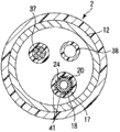
图4是沿图3的IV-IV线的剖视图。Fig. 4 is a sectional view taken along line IV-IV of Fig. 3 .
图5是示出本发明的第二实施方式涉及的内窥镜装置的处置器具的末端方向侧的部位的结构的平面图。5 is a plan view showing the configuration of a portion on the distal direction side of the treatment instrument of the endoscope apparatus according to the second embodiment of the present invention.
图6是沿图5的VI-VI线的剖视图。Fig. 6 is a cross-sectional view along line VI-VI of Fig. 5 .
图7是示出本发明的第一及第二实施方式的变形例涉及的内窥镜装置的处置器具贯穿插入通道的内部结构的剖视图。7 is a cross-sectional view showing an internal structure of a treatment instrument insertion channel of an endoscope device according to a modification example of the first and second embodiments of the present invention.
图8是示出本发明的第三实施方式涉及的内窥镜装置的处置器具的结构的框图。8 is a block diagram showing the configuration of a treatment instrument of an endoscope apparatus according to a third embodiment of the present invention.
图9是示出在与内窥镜分开的管状体中设置有处置器具贯穿插入通道的本发明的变形例涉及的内窥镜装置的末端方向侧的部位的结构的概略图。9 is a schematic diagram showing the structure of a portion on the distal direction side of an endoscope device according to a modification of the present invention in which a treatment instrument insertion channel is provided in a tubular body separate from the endoscope.
具体实施方式 Detailed ways
(第一实施方式)(first embodiment)
参照图1至图4对本发明的第一实施方式进行说明。A first embodiment of the present invention will be described with reference to FIGS. 1 to 4 .
图1及图2是示出本实施方式的内窥镜装置1的图。如图1所示,内窥镜装置1具有对患处等被摄体进行摄像的内窥镜2。内窥镜2具有:插入体腔内的内窥镜插入部4;和设置成比内窥镜插入部4更靠近基端方向侧的内窥镜操作部6。内窥镜操作部6与通用软线8的一端连接。通用软线8的另一端经由镜体连接器(スコ一プコネクタ)9与图像观察装置、照明电源装置(均未图示)等连接。1 and 2 are diagrams showing an endoscope apparatus 1 according to this embodiment. As shown in FIG. 1 , an endoscope apparatus 1 includes an
内窥镜插入部4包括:硬质的末端硬性部10;内窥镜弯曲部12,其设置成比末端硬性部10更靠近基端方向侧,并且进行弯曲工作;以及长条形且具有挠性的内窥镜挠性管部14,其设置成比内窥镜弯曲部12更靠近基端方向侧。The
如图2所示,在内窥镜2的内窥镜操作部6配设有处置器具插入口16。内周面部17从处置器具插入口16开始,穿过内窥镜挠性管部14及内窥镜弯曲部12,一直延伸设置到末端硬性部10。通过内周面部17,处置器具贯穿插入通道18被限定。在末端硬性部10的末端面上设置有作为处置器具贯穿插入通道18的末端的处置器具用口19。As shown in FIG. 2 , the
在内窥镜2的处置器具贯穿插入通道18,以在纵长方向上进退自如的方式贯穿插入有处置器具20。处置器具20包括:插入体腔内的处置器具插入部22;和设置成比处置器具插入部22更靠近基端方向侧的处置器具操作部23。处置器具插入部22包括:在纵长方向上延伸设置并具有挠性的处置器具主体24;和设置成比处置器具主体24更靠近末端方向侧并用于进行处置的末端处置部26。在处置器具主体24和末端处置部26之间设置有旋转关节部27。通过旋转关节部27工作,末端处置部26相对于处置器具主体24绕轴线方向旋转。另外,在末端处置部26设置有用于把持组织等的把持部28。The
如图2所示,在旋转关节部27设置有马达31。马达31经由电导线32与设置于处置器具操作部23的输入部33连接。通过在输入部33处进行的旋转操作,马达31进行驱动,旋转关节部27工作。通过旋转关节部27工作,末端处置部26相对于处置器具主体24绕轴线方向旋转。此外,输入部33与线等把持操作传递部件(未图示)连接。在输入部33进行的把持操作经由把持操作传递部件被传递给把持部28。由此,把持部28进行把持组织等的把持动作。As shown in FIG. 2 , a
图3是示出内窥镜装置1的末端方向侧的部位的结构的图,图4是沿图3的IV-IV线的剖视图。如图3所示,在内窥镜2的末端硬性部10的末端面设置有观察窗35及照明窗36。设置于末端硬性部10的摄像元件(未图示)经由观察窗35进行对被摄体的拍摄。摄像元件与摄像缆线37(参照图4)连接。摄像缆线37穿过内窥镜插入部4、内窥镜操作部6以及通用软线8的内部,并与图像观察装置(未图示)连接。由摄像元件拍摄到的被摄体像经由摄像缆线37被输出到图像观察装置。照明窗36与导光管38(参照图4)光学连接。导光管38穿过内窥镜插入部4、内窥镜操作部6以及通用软线8的内部,并与照明电源装置(未图示)光学连接。从照明电源装置射出的出射光通过导光管38被导光,并经由照明窗36照射被摄体。FIG. 3 is a diagram showing the configuration of a portion on the distal direction side of the endoscope device 1 , and FIG. 4 is a cross-sectional view taken along line IV-IV in FIG. 3 . As shown in FIG. 3 , an observation window 35 and an illumination window 36 are provided on the distal surface of the distal
另外,在处置器具20被贯穿插入于处置器具贯穿插入通道18的状态下,处置器具20从末端硬性部10的末端面的处置器具用口19向末端方向突出。在末端处置部26的外周面设置有第一标识39A,在处置器具主体24的外周面设置有多个第二标识39B。由此,手术操作者可以根据由内窥镜2的摄像元件拍摄到的图像来确认第一标识39A与第二标识39B的位置关系。并且,根据第一标识39A与第二标识39B的位置关系,能够识别出末端处置部26的中间位置(初始位置)、以及末端处置部26相对于处置器具主体24从中间位置绕轴线方向旋转的旋转量。因此,能够识别出输入部33处的旋转操作是否被适当地传递。In addition, when the
如图4所示,在内窥镜2的内周面部17的末端方向侧的部位,沿处置器具贯穿插入通道18的周向并列设置有向内周侧突出的多个凸部41。凸部41被设置成在纵长方向具有预定的长度。在处置器具20被贯穿插入于处置器具贯穿插入通道18的状态下,每个凸部41与处置器具主体24的外周面接触。根据这样的结构,当处置器具主体24相对于内窥镜2绕轴线方向旋转时,在凸部41与处置器具主体24的末端方向侧的部位的外周面接触的接触部,向与处置器具主体24的旋转方向相反的方向施加有摩擦力。即,凸部41成为摩擦力施加部,该摩擦力施加部对凸部41(内周面部17的末端方向侧的部位)与处置器具主体24的末端方向侧的部位的外周面接触的接触部施加摩擦力。通过由凸部41施加的摩擦力,处置器具主体24的末端方向侧的部位的绕轴线方向的旋转被约束。此外,处置器具20相对于内窥镜2沿纵长方向的进退动作并不通过凸部41被约束。As shown in FIG. 4 , a plurality of
接下来,对本实施方式涉及的内窥镜装置1的作用进行说明。在内窥镜装置1中,将处置器具20贯穿插入到内窥镜2的处置器具贯穿插入通道18并进行处置。在内窥镜装置1的处置中,存在利用末端处置部26的把持部28把持组织等的情况。当利用把持部28进行把持动作时,对被设置成比旋转关节部27更靠近末端方向侧的把持部28施加有力。当在该状态下使旋转关节部27工作从而进行末端处置部26的旋转操作时,比旋转关节部27更靠近基端方向侧的处置器具主体24的末端方向侧的部位欲向与旋转操作所产生的旋转方向相反的方向旋转。Next, the operation of the endoscope apparatus 1 according to the present embodiment will be described. In the endoscope apparatus 1 , the
在内窥镜装置1中,当处置器具20贯穿插入于处置器具贯穿插入通道18时,每个凸部41与处置器具主体24的外周面接触。因此,当处置器具主体24相对于内窥镜2绕轴线方向旋转时,在凸部41(内周面部17的末端方向侧的部位)与处置器具主体24的末端方向侧的部位的外周面接触的接触部,向处置器具主体24的旋转方向的相反方向施加有摩擦力。通过由凸部41施加的摩擦力,处置器具主体24的末端方向侧的部位向与旋转操作所产生的旋转方向相反的方向的旋转被约束。通过对比旋转关节部27更靠近基端方向侧的处置器具主体24的末端方向侧的部位的绕轴线方向的旋转进行约束,即使在利用把持部28把持了组织等的状态(对末端处置部26施加有力的状态)下,也能够将旋转操作适当地传递给比旋转关节部27更靠近末端方向侧的末端处置部26。由此,末端处置部26相对于处置器具主体24绕轴线方向适当地进行旋转运动。In the endoscope apparatus 1 , when the
因此,在所述结构的内窥镜装置1中起到以下效果。即,在本实施方式涉及的内窥镜装置1中,当处置器具20贯穿插入于处置器具贯穿插入通道18时,每个凸部41与处置器具主体24的外周面接触。因此,当处置器具主体24相对于内窥镜2绕轴线方向旋转时,在凸部41(内周面部17的末端方向侧的部位)与处置器具主体24的末端方向侧的部位的外周面接触的接触部,向处置器具主体24的旋转方向的相反方向施加有摩擦力。通过由凸部41施加的摩擦力,当在利用把持部28把持了组织等的状态(对末端处置部26施加有力的状态)下进行末端处置部26的旋转运动时,处置器具主体24的末端方向侧的部位向与旋转操作所产生的旋转方向相反的方向的旋转被约束。通过对比旋转关节部27更靠近基端方向侧的处置器具主体24的末端方向侧的部位的绕轴线方向的旋转进行约束,即使在对末端处置部26施加有力的状态下,也能够将旋转操作适当地传递给相对于旋转关节部27设置于末端方向侧的末端处置部26。Therefore, the following effects can be obtained in the endoscope apparatus 1 configured as described above. That is, in the endoscope apparatus 1 according to the present embodiment, when the
(第二实施方式)(second embodiment)
接下来,参照图5及图6对第二实施方式进行说明。此外,对与第一实施方式相同的部分及具有相同功能的部分标以相同的标号,并省略其说明。Next, a second embodiment will be described with reference to FIGS. 5 and 6 . In addition, the same code|symbol is attached|subjected to the same part and the part which has the same function as 1st Embodiment, and the description is abbreviate|omitted.
图5是示出第二实施方式涉及的处置器具50的末端方向侧的部位的结构的图,图6是沿图5的VI-VI线的剖视图。如图5所示,与第一实施方式的处置器具20一样,处置器具50包括处置器具主体24和末端处置部26,并且在处置器具主体24与末端处置部26之间设置有旋转关节部27。FIG. 5 is a diagram showing the configuration of a portion on the distal direction side of a
如图5及图6所示,在处置器具50的处置器具主体24的末端方向侧的部位的外周面,沿处置器具50的周向并列设置有向外周侧突出的多个凸部51。凸部51被设置成在纵长方向具有预定的长度。在处置器具50被贯穿插入于处置器具贯穿插入通道18的状态下,每个凸部51与内周面部17接触。根据这样的结构,当处置器具主体24相对于内窥镜2绕轴线方向旋转时,在凸部51与内周面部17的末端方向侧的部位接触的接触部,向与处置器具主体24的旋转方向相反的方向施加有摩擦力。即,凸部51成为摩擦力施加部,该摩擦力施加部对内周面部17的末端方向侧的部位和凸部51(处置器具主体24的末端方向侧的部位的外周面)接触的接触部施加摩擦力。通过由凸部51施加的摩擦力,处置器具主体24的末端方向侧的部位的绕轴线方向的旋转被约束。此外,处置器具50相对于内窥镜2沿纵长方向的进退动作并不通过凸部51被约束。As shown in FIGS. 5 and 6 , on the outer peripheral surface of the
接下来,对本实施方式涉及的内窥镜装置1的作用进行说明。在内窥镜装置1中,将处置器具50贯穿插入到内窥镜2的处置器具贯穿插入通道18并进行处置。在内窥镜装置1的处置中,存在利用末端处置部26的把持部28把持组织等的情况。当利用把持部28进行把持动作时,对被设置成比旋转关节部27更靠近末端方向侧的把持部28施加有力。当在该状态下使旋转关节部27工作从而进行末端处置部26的旋转操作时,比旋转关节部27更靠近基端方向侧的处置器具主体24的末端方向侧的部位欲向与旋转操作所产生的旋转方向相反的方向旋转。Next, the operation of the endoscope apparatus 1 according to the present embodiment will be described. In the endoscope apparatus 1 , the
在内窥镜装置1中,当处置器具50贯穿插入于处置器具贯穿插入通道18时,每个凸部51与内周面部17接触。因此,当处置器具主体24相对于内窥镜2绕轴线方向旋转时,在内周面部17的末端方向侧的部位和凸部51(处置器具主体24的末端方向侧的部位的外周面)接触的接触部,向处置器具主体24的旋转方向的相反方向施加有摩擦力。通过由凸部51施加的摩擦力,处置器具主体24的末端方向侧的部位向与旋转操作所产生的旋转方向相反的方向的旋转被约束。通过对比旋转关节部27更靠近基端方向侧的处置器具主体24的末端方向侧的部位的绕轴线方向的旋转进行约束,即使在利用把持部28把持了组织等的状态(对末端处置部26施加有力的状态)下,也能够将旋转操作适当地传递给相对于旋转关节部27设置于末端方向侧的末端处置部26。由此,末端处置部26相对于处置器具主体24绕轴线方向适当地进行旋转运动。In the endoscope apparatus 1 , when the
因此,在所述结构的内窥镜装置1中起到以下效果。即,在本实施方式涉及的内窥镜装置1中,当处置器具50贯穿插入于处置器具贯穿插入通道18时,每个凸部51与内周面部17接触。因此,当处置器具主体24相对于内窥镜2绕轴线方向旋转时,在内周面部17的末端方向侧的部位和凸部51(处置器具主体24的末端方向侧的部位的外周面)接触的接触部,向处置器具主体24的旋转方向的相反方向施加有摩擦力。通过由凸部51施加的摩擦力,当在利用把持部28把持了组织等的状态(对末端处置部26施加有力的状态)下进行末端处置部26的旋转运动时,处置器具主体24的末端方向侧的部位向与旋转操作所产生的旋转方向相反的方向的旋转被约束。通过对比旋转关节部27更靠近基端方向侧的处置器具主体24的末端方向侧的部位的绕轴线方向的旋转进行约束,即使在对末端处置部26施加有力的状态下,也能够将旋转操作适当地传递给相对于旋转关节部27设置于末端方向侧的末端处置部26。Therefore, the following effects can be obtained in the endoscope apparatus 1 configured as described above. That is, in the endoscope apparatus 1 according to the present embodiment, when the
(第一实施方式及第二实施方式的变形例)(Modifications of the first embodiment and the second embodiment)
此外,作为第一及第二实施方式的变形例,如图7所示,也可以在内周面部17的末端方向侧的部位设置向内周侧突出的多个第一凸部41,同时在处置器具55的处置器具主体24的末端方向侧的部位的外周面设置向外周侧突出的多个第二凸部51。在所述内窥镜装置1中,在处置器具55被贯穿插入于处置器具贯穿插入通道18的状态下,第一凸部41与第二凸部51接触。根据这样的结构,当处置器具主体24相对于内窥镜2绕轴线方向旋转时,在第一凸部41与第二凸部51接触的接触部,向与处置器具主体24的旋转方向相反的方向施加有摩擦力。即,第一凸部41和第二凸部51成为摩擦力施加部,该摩擦力施加部对第一凸部41(内周面部17的末端方向侧的部位)与第二凸部51(处置器具主体24的末端方向侧的部位的外周面)接触的接触部施加摩擦力。In addition, as a modified example of the first and second embodiments, as shown in FIG. 7 , a plurality of
以上,根据第一及第二实施方式以及所述第一及第二实施方式的变形例,在本发明的内窥镜装置1中,可以包括从内周面部17的末端方向侧的部位向内周侧突出的多个第一凸部41。另外,内窥镜装置1也可以包括从处置器具主体24的末端方向侧的部位的外周面向外周侧突出的多个第二凸部51。在以上那样的结构中,第一凸部41和/或第二凸部51成为摩擦力施加部,当处置器具主体24相对于内窥镜2绕轴线方向旋转时,该摩擦力施加部对内周面部17的末端方向侧的部位与处置器具主体24的末端方向侧的部位的外周面接触的接触部施加摩擦力。As described above, according to the first and second embodiments and the modified examples of the first and second embodiments, in the endoscope device 1 of the present invention, it is possible to include the inner
(第三实施方式)(third embodiment)
接下来,参照图8对第三实施方式进行说明。此外,对与第一实施方式相同的部分及具有相同功能的部分标以相同的标号,并省略其说明。Next, a third embodiment will be described with reference to FIG. 8 . In addition, the same code|symbol is attached|subjected to the same part and the part which has the same function as 1st Embodiment, and the description is abbreviate|omitted.
图8是示出第三实施方式涉及的处置器具60的图。如图8所示,与第一实施方式的处置器具20一样,处置器具60包括处置器具插入部22和处置器具操作部23。处置器具插入部22包括处置器具主体24和末端处置部26,并且在处置器具主体24与末端处置部26之间设置有旋转关节部27。FIG. 8 is a diagram showing a
在处置器具主体24的末端方向侧的部位的外周面设置有在纵长方向上具有预定长度的球囊61。球囊61与输气管62的末端连接。输气管62穿过处置器具主体24及处置器具操作部23的内部,并且其基端与设置于处置器具60的外部的输气泵63连接。与在日本特开2001-327460号公报中公开的内窥镜装置一样,通过从输气泵63经由输气管62向球囊61进行输气,球囊61膨胀。由此,处置器具主体24的末端方向侧的部位能够扩大直径。A
在处置器具操作部23设置有与旋转关节部27的马达31连接的检测部65。通过检测部65对旋转关节部27正在工作的状态(末端处置部26绕轴线方向进行旋转的状态)进行检测。检测部65与设置于处置器具操作部23的控制部67连接。控制部67与处置器具操作部23的输入部33及输气管62连接。根据这样的结构,通过在输入部33处进行的操作,能够利用手动使球囊61膨胀。另外,也可以在通过检测部65检测出旋转关节部27正在工作的状态时,通过控制部67对输气泵63进行控制,以使其处于对球囊61进行输气的状态。由此,能够根据旋转关节部27的工作状态,自动地使球囊61膨胀。The
当处置器具60被贯穿插入于处置器具贯穿插入通道18并且球囊61膨胀了的状态下,球囊61与内周面部17接触。根据这样的结构,当处置器具主体24相对于内窥镜2绕轴线方向旋转时,在球囊61与内周面部17的末端方向侧的部位接触的接触部,向与处置器具主体24的旋转方向相反的方向施加有摩擦力。即,球囊61成为摩擦力施加部,该摩擦力施加部对内周面部17的末端方向侧的部位和球囊61(处置器具主体24的末端方向侧的部位的外周面)接触的接触部施加摩擦力。通过由球囊61施加的摩擦力,处置器具主体24的末端方向侧的部位的绕轴线方向的旋转被约束。此外,通过使球囊61收缩,处置器具60能够相对于内窥镜2沿纵长方向进行进退动作。When the
接下来,对本实施方式涉及的内窥镜装置1的作用进行说明。在内窥镜装置1中,将处置器具60贯穿插入到内窥镜2的处置器具贯穿插入通道18并进行处置。在内窥镜装置1的处置中,存在利用末端处置部26的把持部28把持组织等的情况。当利用把持部28进行把持动作时,对被设置成比旋转关节部27更靠近末端方向侧的把持部28施加有力。当在该状态下使旋转关节部27工作从而进行末端处置部26的旋转操作时,比旋转关节部27更靠近基端方向侧的处置器具主体24的末端方向侧的部位欲向与旋转操作所产生的旋转方向相反的方向旋转。另外,当旋转关节部27工作时,利用检测部65检测出旋转关节部27正在工作的状态,并通过控制部67将输气泵63控制成对球囊61进行输气的状态。由此,球囊61膨胀,处置器具主体24的末端方向侧的部位扩大直径。此外,此时也可以通过处置器具操作部23的输入部33来手动进行使球囊61膨胀的操作。Next, the operation of the endoscope apparatus 1 according to the present embodiment will be described. In the endoscope apparatus 1 , the
在内窥镜装置1中,当处置器具60贯穿插入于处置器具贯穿插入通道18并且球囊61膨胀时,球囊61与内周面部17接触。因此,当处置器具主体24相对于内窥镜2绕轴线方向旋转时,在内周面部17的末端方向侧的部位和球囊61(处置器具主体24的末端方向侧的部位的外周面)接触的接触部,向处置器具主体24的旋转方向的相反方向施加有摩擦力。通过由球囊61施加的摩擦力,处置器具主体24的末端方向侧的部位向与旋转操作所产生的旋转方向相反的方向的旋转被约束。通过对比旋转关节部27更靠近基端方向侧的处置器具主体24的末端方向侧的部位的绕轴线方向的旋转进行约束,即使在利用把持部28把持了组织等的状态(对末端处置部26施加有力的状态)下,也能够将旋转操作适当地传递给相对于旋转关节部27设置在末端方向侧的末端处置部26。由此,末端处置部26相对于处置器具主体24绕轴线方向适当地进行旋转运动。In the endoscope device 1 , when the
因此,在所述结构的内窥镜装置1中起到以下效果。即,在本实施方式涉及的内窥镜装置1中,当处置器具60贯穿插入于处置器具贯穿插入通道18并且球囊61膨胀时,球囊61与内周面部17接触。因此,当处置器具主体24相对于内窥镜2绕轴线方向旋转时,在内周面部17的末端方向侧的部位和球囊61(处置器具主体24的末端方向侧的部位的外周面)接触的接触部,向处置器具主体24的旋转方向的相反方向施加有摩擦力。通过由球囊61施加的摩擦力,当在利用把持部28把持了组织等的状态(对末端处置部26施加有力的状态)下进行末端处置部26的旋转运动时,处置器具主体24的末端方向侧的部位向与旋转操作所产生的旋转方向相反的方向的旋转被约束。通过对比旋转关节部27更靠近基端方向侧的处置器具主体24的末端方向侧的部位的绕轴线方向的旋转进行约束,即使在对末端处置部26施加有力的状态下,也能够将旋转操作适当地传递给设置于旋转关节部27的末端方向侧的末端处置部26。Therefore, the following effects can be obtained in the endoscope apparatus 1 configured as described above. That is, in the endoscope apparatus 1 according to the present embodiment, when the
(其他变形例)(Other modifications)
在上述实施方式中,通过从内周面部17的末端方向侧的部位向内周侧突出的多个第一凸部41以及从处置器具主体24的末端方向侧的部位的外周面向外周侧突出的多个第二凸部51中的至少一方、或者设置于处置器具主体24的末端方向侧的部位的外周面的能够膨胀的球囊61,构成了摩擦力施加部。但是,在本发明的内窥镜装置1中,只需设置有这样摩擦力施加部即可:当处置器具主体24相对于内窥镜2绕轴线方向旋转时,所述摩擦力施加部对内周面部17的末端方向侧的部位与处置器具主体24的末端方向侧的部位的外周面接触的接触部施加摩擦力。In the above-described embodiment, the plurality of
另外,在上述实施方式中,在旋转关节部27设置有马达31,通过驱动马达31使旋转关节部27工作,由此,末端处置部26相对于处置器具主体24进行旋转运动,但使旋转关节部27工作的结构并不仅限于此。例如,也可以是以下结构:在旋转关节部27设置锥齿轮,并使锥齿轮与线等旋转操作传递部件连接。在所述处置器具中,通过旋转操作传递部件在纵长方向上的进退动作,锥齿轮被驱动,从而旋转关节部27工作。In addition, in the above-mentioned embodiment, the
此外,在上述实施方式中,对供处置器具贯穿插入的处置器具贯穿插入通道18进行限定的内周面部17被设置于内窥镜2,但并不仅限于此。例如,如图9所示,在内窥镜装置70设置有与内窥镜2分开的管状体71。在该情况下,也可以在管状体71中设置对贯穿插入处置器具75的处置器具贯穿插入通道(未图示)进行限定的内周面部73。In addition, in the above-described embodiment, the inner
以上,对本发明的实施方式进行了说明,当然,本发明并非仅限于所述实施方式,在不脱离本发明的要旨的范围内可以进行各种变形。As mentioned above, although embodiment of this invention was described, of course, this invention is not limited to the said embodiment, Various deformation|transformation is possible in the range which does not deviate from the summary of this invention.
Claims (5)
Applications Claiming Priority (3)
| Application Number | Priority Date | Filing Date | Title |
|---|---|---|---|
| JP2010-042571 | 2010-02-26 | ||
| JP2010042571 | 2010-02-26 | ||
| PCT/JP2010/071241 WO2011104960A1 (en) | 2010-02-26 | 2010-11-29 | Endoscope apparatus |
Publications (2)
| Publication Number | Publication Date |
|---|---|
| CN102413755A true CN102413755A (en) | 2012-04-11 |
| CN102413755B CN102413755B (en) | 2015-07-01 |
Family
ID=44506397
Family Applications (1)
| Application Number | Title | Priority Date | Filing Date |
|---|---|---|---|
| CN201080019579.6A Active CN102413755B (en) | 2010-02-26 | 2010-11-29 | endoscopic device |
Country Status (5)
| Country | Link |
|---|---|
| US (1) | US20110288371A1 (en) |
| EP (1) | EP2401952B1 (en) |
| JP (1) | JP4813630B2 (en) |
| CN (1) | CN102413755B (en) |
| WO (1) | WO2011104960A1 (en) |
Cited By (4)
| Publication number | Priority date | Publication date | Assignee | Title |
|---|---|---|---|---|
| CN107072493A (en) * | 2015-06-05 | 2017-08-18 | 奥林巴斯株式会社 | Insertion apparatus |
| CN109496135A (en) * | 2016-06-01 | 2019-03-19 | 恩达马斯特有限公司 | Endoscopy system component |
| CN110113981A (en) * | 2016-12-26 | 2019-08-09 | 天主教关东大学校产学协力团 | Endoscopic treatment part |
| CN116568198A (en) * | 2020-11-30 | 2023-08-08 | 富士胶片株式会社 | Endoscope treatment instrument, endoscope device and treatment method |
Families Citing this family (1)
| Publication number | Priority date | Publication date | Assignee | Title |
|---|---|---|---|---|
| WO2020049713A1 (en) * | 2018-09-07 | 2020-03-12 | オリンパス株式会社 | Endoscope system |
Citations (9)
| Publication number | Priority date | Publication date | Assignee | Title |
|---|---|---|---|---|
| JPH08224244A (en) * | 1995-02-22 | 1996-09-03 | Olympus Optical Co Ltd | Medical manipulator |
| WO2006033671A2 (en) * | 2004-04-15 | 2006-03-30 | Wilson-Cook Medical Inc. | Endoscopic surgical access devices and methods of articulating an external accessory channel |
| US20070225554A1 (en) * | 2006-03-22 | 2007-09-27 | Boston Scientific Scimed, Inc. | Endoscope working channel with multiple functionality |
| US20080033238A1 (en) * | 2006-06-07 | 2008-02-07 | Olympus Medical Systems Corp. | Treatment tool for endoscope |
| CN101184446A (en) * | 2005-05-31 | 2008-05-21 | 奥林巴斯医疗株式会社 | Mucosa peeling device and method of mucosal peeling |
| CN101370435A (en) * | 2006-02-21 | 2009-02-18 | 奥林巴斯医疗株式会社 | Endoscopy Systems and Medical Devices |
| JP2009142513A (en) * | 2007-12-17 | 2009-07-02 | Hoya Corp | Bipolar high-frequency treatment instrument for endoscope |
| US20090182194A1 (en) * | 2008-01-11 | 2009-07-16 | Boston Scientific Scimed, Inc. | Positioning system for securing a treatment instrument at the end of a medical device |
| JP2010035668A (en) * | 2008-08-01 | 2010-02-18 | Hoya Corp | Treatment tool for endoscope |
Family Cites Families (13)
| Publication number | Priority date | Publication date | Assignee | Title |
|---|---|---|---|---|
| US6659939B2 (en) * | 1998-11-20 | 2003-12-09 | Intuitive Surgical, Inc. | Cooperative minimally invasive telesurgical system |
| JP2001327460A (en) | 2000-05-18 | 2001-11-27 | Olympus Optical Co Ltd | Endoscope device |
| US7766894B2 (en) * | 2001-02-15 | 2010-08-03 | Hansen Medical, Inc. | Coaxial catheter system |
| US7338513B2 (en) * | 2003-10-30 | 2008-03-04 | Cambridge Endoscopic Devices, Inc. | Surgical instrument |
| US20080021274A1 (en) * | 2005-01-05 | 2008-01-24 | Avantis Medical Systems, Inc. | Endoscopic medical device with locking mechanism and method |
| EP1707153B1 (en) * | 2005-03-29 | 2012-02-01 | Kabushiki Kaisha Toshiba | Manipulator |
| WO2006129726A1 (en) * | 2005-05-31 | 2006-12-07 | Olympus Medical Systems Corp. | Device and method for mucosal detachment |
| JP4425223B2 (en) * | 2006-02-17 | 2010-03-03 | Hoya株式会社 | High frequency knife for endoscope |
| JP4441496B2 (en) * | 2006-02-20 | 2010-03-31 | Hoya株式会社 | Bipolar high-frequency treatment instrument for endoscope |
| US9289266B2 (en) * | 2006-12-01 | 2016-03-22 | Boston Scientific Scimed, Inc. | On-axis drive systems and methods |
| JP5237608B2 (en) * | 2007-10-25 | 2013-07-17 | オリンパスメディカルシステムズ株式会社 | Medical equipment |
| US20090131752A1 (en) * | 2007-11-19 | 2009-05-21 | Chul Hi Park | Inflatable artificial muscle for elongated instrument |
| JP2011000326A (en) * | 2009-06-19 | 2011-01-06 | Ritsumeikan | Bend driving device, endoscope with the same, and bend driving device for endoscope |
-
2010
- 2010-11-29 EP EP10846623.6A patent/EP2401952B1/en not_active Not-in-force
- 2010-11-29 JP JP2011524035A patent/JP4813630B2/en active Active
- 2010-11-29 CN CN201080019579.6A patent/CN102413755B/en active Active
- 2010-11-29 WO PCT/JP2010/071241 patent/WO2011104960A1/en not_active Ceased
-
2011
- 2011-06-16 US US13/162,197 patent/US20110288371A1/en not_active Abandoned
Patent Citations (9)
| Publication number | Priority date | Publication date | Assignee | Title |
|---|---|---|---|---|
| JPH08224244A (en) * | 1995-02-22 | 1996-09-03 | Olympus Optical Co Ltd | Medical manipulator |
| WO2006033671A2 (en) * | 2004-04-15 | 2006-03-30 | Wilson-Cook Medical Inc. | Endoscopic surgical access devices and methods of articulating an external accessory channel |
| CN101184446A (en) * | 2005-05-31 | 2008-05-21 | 奥林巴斯医疗株式会社 | Mucosa peeling device and method of mucosal peeling |
| CN101370435A (en) * | 2006-02-21 | 2009-02-18 | 奥林巴斯医疗株式会社 | Endoscopy Systems and Medical Devices |
| US20070225554A1 (en) * | 2006-03-22 | 2007-09-27 | Boston Scientific Scimed, Inc. | Endoscope working channel with multiple functionality |
| US20080033238A1 (en) * | 2006-06-07 | 2008-02-07 | Olympus Medical Systems Corp. | Treatment tool for endoscope |
| JP2009142513A (en) * | 2007-12-17 | 2009-07-02 | Hoya Corp | Bipolar high-frequency treatment instrument for endoscope |
| US20090182194A1 (en) * | 2008-01-11 | 2009-07-16 | Boston Scientific Scimed, Inc. | Positioning system for securing a treatment instrument at the end of a medical device |
| JP2010035668A (en) * | 2008-08-01 | 2010-02-18 | Hoya Corp | Treatment tool for endoscope |
Cited By (7)
| Publication number | Priority date | Publication date | Assignee | Title |
|---|---|---|---|---|
| CN107072493A (en) * | 2015-06-05 | 2017-08-18 | 奥林巴斯株式会社 | Insertion apparatus |
| CN107072493B (en) * | 2015-06-05 | 2019-01-29 | 奥林巴斯株式会社 | Insert device |
| CN109496135A (en) * | 2016-06-01 | 2019-03-19 | 恩达马斯特有限公司 | Endoscopy system component |
| CN109496135B (en) * | 2016-06-01 | 2021-10-26 | 恩达马斯特有限公司 | Endoscopy system component |
| CN110113981A (en) * | 2016-12-26 | 2019-08-09 | 天主教关东大学校产学协力团 | Endoscopic treatment part |
| CN110113981B (en) * | 2016-12-26 | 2022-08-05 | 天主教关东大学校产学协力团 | Treatment tool for endoscope |
| CN116568198A (en) * | 2020-11-30 | 2023-08-08 | 富士胶片株式会社 | Endoscope treatment instrument, endoscope device and treatment method |
Also Published As
| Publication number | Publication date |
|---|---|
| EP2401952B1 (en) | 2016-12-28 |
| US20110288371A1 (en) | 2011-11-24 |
| JP4813630B2 (en) | 2011-11-09 |
| EP2401952A4 (en) | 2012-05-02 |
| JPWO2011104960A1 (en) | 2013-06-17 |
| CN102413755B (en) | 2015-07-01 |
| WO2011104960A1 (en) | 2011-09-01 |
| EP2401952A1 (en) | 2012-01-04 |
Similar Documents
| Publication | Publication Date | Title |
|---|---|---|
| CN101637408B (en) | Endoscope insertion aid and endoscope apparatus | |
| JP4772446B2 (en) | Endoscope insertion aid and endoscope apparatus | |
| JP5296351B2 (en) | Endoscope insertion device | |
| CN101569550B (en) | Endoscope system using manipulator apparatus | |
| CN107847110B (en) | Manipulators and Medical Systems | |
| CN104394752B (en) | Plug assistive device | |
| CN102413755B (en) | endoscopic device | |
| JP5171076B2 (en) | Endoscope device | |
| EP4568558A1 (en) | Medical device with integrated instrument and related methods | |
| US20130331645A1 (en) | Endoscopic device and endoscope treatment system | |
| JP3826928B2 (en) | Endoscope insertion aid | |
| JP5116985B2 (en) | Endoscope | |
| JP3864315B2 (en) | Endoscope device | |
| US12357153B2 (en) | Rising base and endoscope | |
| JP5030449B2 (en) | Endoscope insertion aid | |
| JP3787724B2 (en) | Endoscope device | |
| JP4546159B2 (en) | Endoscope and endoscope treatment system | |
| US20240293010A1 (en) | Insertion assisting tool | |
| WO2020080236A1 (en) | Endoscope and treatment tool channel unit | |
| JP4786985B2 (en) | Endoscope | |
| JP2005230083A (en) | Endoscope | |
| JP2005230085A (en) | Over-tube with balloon | |
| EP3311728A1 (en) | Insertion apparatus and insertion device | |
| JP2007195688A (en) | Endoscope insertion assisting appliance | |
| CN112074222A (en) | Driving force transmission mechanism of endoscope |
Legal Events
| Date | Code | Title | Description |
|---|---|---|---|
| C06 | Publication | ||
| PB01 | Publication | ||
| C10 | Entry into substantive examination | ||
| SE01 | Entry into force of request for substantive examination | ||
| C14 | Grant of patent or utility model | ||
| GR01 | Patent grant | ||
| C41 | Transfer of patent application or patent right or utility model | ||
| TR01 | Transfer of patent right |
Effective date of registration: 20151117 Address after: Tokyo, Japan, Japan Patentee after: Olympus Corporation Address before: Tokyo, Japan, Japan Patentee before: Olympus Medical Systems Corp. |