CN102377224A - Wireless charging system - Google Patents
Wireless charging system Download PDFInfo
- Publication number
- CN102377224A CN102377224A CN2011102277725A CN201110227772A CN102377224A CN 102377224 A CN102377224 A CN 102377224A CN 2011102277725 A CN2011102277725 A CN 2011102277725A CN 201110227772 A CN201110227772 A CN 201110227772A CN 102377224 A CN102377224 A CN 102377224A
- Authority
- CN
- China
- Prior art keywords
- power
- equipment
- auxilliary
- wireless charging
- charging system
- Prior art date
- Legal status (The legal status is an assumption and is not a legal conclusion. Google has not performed a legal analysis and makes no representation as to the accuracy of the status listed.)
- Pending
Links
Images


Classifications
-
- H—ELECTRICITY
- H02—GENERATION; CONVERSION OR DISTRIBUTION OF ELECTRIC POWER
- H02J—ELECTRIC POWER NETWORKS; CIRCUIT ARRANGEMENTS OR SYSTEMS FOR SUPPLYING OR DISTRIBUTING ELECTRIC POWER; SYSTEMS FOR STORING ELECTRIC ENERGY
- H02J50/00—Circuit arrangements or systems for wireless supply or distribution of electric power
- H02J50/10—Circuit arrangements or systems for wireless supply or distribution of electric power using inductive coupling
- H02J50/12—Circuit arrangements or systems for wireless supply or distribution of electric power using inductive coupling of the resonant type
-
- H—ELECTRICITY
- H02—GENERATION; CONVERSION OR DISTRIBUTION OF ELECTRIC POWER
- H02J—ELECTRIC POWER NETWORKS; CIRCUIT ARRANGEMENTS OR SYSTEMS FOR SUPPLYING OR DISTRIBUTING ELECTRIC POWER; SYSTEMS FOR STORING ELECTRIC ENERGY
- H02J50/00—Circuit arrangements or systems for wireless supply or distribution of electric power
- H02J50/40—Circuit arrangements or systems for wireless supply or distribution of electric power using two or more transmitting or receiving devices
-
- H—ELECTRICITY
- H02—GENERATION; CONVERSION OR DISTRIBUTION OF ELECTRIC POWER
- H02J—ELECTRIC POWER NETWORKS; CIRCUIT ARRANGEMENTS OR SYSTEMS FOR SUPPLYING OR DISTRIBUTING ELECTRIC POWER; SYSTEMS FOR STORING ELECTRIC ENERGY
- H02J50/00—Circuit arrangements or systems for wireless supply or distribution of electric power
- H02J50/60—Circuit arrangements or systems for wireless supply or distribution of electric power responsive to the presence of foreign objects, e.g. detection of living beings
-
- H—ELECTRICITY
- H02—GENERATION; CONVERSION OR DISTRIBUTION OF ELECTRIC POWER
- H02J—ELECTRIC POWER NETWORKS; CIRCUIT ARRANGEMENTS OR SYSTEMS FOR SUPPLYING OR DISTRIBUTING ELECTRIC POWER; SYSTEMS FOR STORING ELECTRIC ENERGY
- H02J50/00—Circuit arrangements or systems for wireless supply or distribution of electric power
- H02J50/80—Circuit arrangements or systems for wireless supply or distribution of electric power involving the exchange of data, concerning supply or distribution of electric power, between transmitting devices and receiving devices
-
- H—ELECTRICITY
- H02—GENERATION; CONVERSION OR DISTRIBUTION OF ELECTRIC POWER
- H02J—ELECTRIC POWER NETWORKS; CIRCUIT ARRANGEMENTS OR SYSTEMS FOR SUPPLYING OR DISTRIBUTING ELECTRIC POWER; SYSTEMS FOR STORING ELECTRIC ENERGY
- H02J50/00—Circuit arrangements or systems for wireless supply or distribution of electric power
- H02J50/005—Mechanical details of housing or structure aiming to accommodate the power transfer means, e.g. mechanical integration of coils, antennas or transducers into emitting or receiving devices
-
- H—ELECTRICITY
- H02—GENERATION; CONVERSION OR DISTRIBUTION OF ELECTRIC POWER
- H02J—ELECTRIC POWER NETWORKS; CIRCUIT ARRANGEMENTS OR SYSTEMS FOR SUPPLYING OR DISTRIBUTING ELECTRIC POWER; SYSTEMS FOR STORING ELECTRIC ENERGY
- H02J7/00—Circuit arrangements for charging or discharging batteries or for supplying loads from batteries
- H02J7/40—Circuit arrangements for charging or discharging batteries or for supplying loads from batteries characterised by the exchange of charge or discharge related data
- H02J7/42—Circuit arrangements for charging or discharging batteries or for supplying loads from batteries characterised by the exchange of charge or discharge related data with electronic devices having internal batteries, e.g. mobile phones
Landscapes
- Engineering & Computer Science (AREA)
- Computer Networks & Wireless Communication (AREA)
- Power Engineering (AREA)
- Charge And Discharge Circuits For Batteries Or The Like (AREA)
Abstract
Disclosed herein is a wireless charging system, including: a primary device that includes a power transmitter adapted to transmit power wirelessly; and a secondary device that includes a power receiver adapted to receive power transmitted wirelessly from the power transmitter, wherein the secondary device also includes a sensor adapted to detect any anomaly in the power transmission path between the power transmitter and receiver.
Description
Technical field
The present invention relates to a kind of can be with the noncontact feed type wireless charging system of noncontact (wireless) mode to electronic equipment (such as the mobile phone that comprises rechargeable battery) power supply.
Background technology
The electromagnetic induction method is known to be the mode that is used for wireless power.
On the other hand, wireless feed and charging system have been paid close attention in recent years based on the magnetic resonance that relies on the EMR electromagnetic resonance phenomenon.
Through widely used electromagnetic induction type noncontact feed method nowadays, the source of power and the destination of power (power receiver side) must be shared magnetic flux.Send for efficient power, be positioned to the source and destination of power each other very near.In addition, it also is important being coupled and aligned.
On the other hand, be that because the principle of EMR electromagnetic resonance phenomenon, it allows to send than the power of the longer distance of electromagnetic induction method, and transmitting efficiency does not worsen because of a little bad aligning even too much based on the noncontact feed method advantage of EMR electromagnetic resonance phenomenon.
Should be noted that the electric field resonance method is based on another method of EMR electromagnetic resonance phenomenon.
Use the wireless feed system of magnetic resonance type, calibrate dispensable, the therefore longer feed distance of realization.
Mention along band, carry compact portable formula electronic equipment in recent years more continually.Each all comprises the auxilliary battery of common periodic charge to use these mobile devices (portable set).
For example; During being applicable to that the above wireless power that power is provided to the power receiver from power transmitter through electromagnetic induction sends; If during power sends, the external object that can generate eddy current (such as coin or key etc.) is provided between power transmitter and receiver, then this not only produces power loss but also the heating of generation external object self.
Therefore, the method for being considered is to add temperature sensor to transmitter, thereby measures the countermeasure of temperature as the heating of antagonism external object.
For example; The open No.2003-153457 of Japan Patent discloses a kind of non-contact charger; Purpose is not only rise to keep in the short as far as possible time, carrying out charging in minimum in the temperature that will be recharged equipment, and if the metal outer object is provided in live part then prevents that also abnormal temperature from rising.
In addition, the open No.2008-172874 of Japan Patent discloses a kind of non-contact charger that aims to provide improved fail safe.The temperature sensor that this charger uses the optimization position on non-contact charger to provide carries out this operation, and if the abnormal temperature that detects the object that is placed on it rise then stop immediately charging.
We can say that these countermeasures are to design to the situation that has a power transmitter and a power receiver is strict.
Summary of the invention
Yet, increase for the increasing demand of the single charger that a plurality of equipment is charged with the noncontact mode.
In the case with necessary be that each a plurality of auxilliary equipment that includes the power receiver can be placed on the main equipment that comprises power transmitter, and power also can be provided in the auxilliary equipment each.
If on the main equipment of configuration as stated, temperature sensor is provided, then must knows the size and the position of all external object.As a result, with the temperature sensor that uses unlimited amount.
This possibly influence cost significantly, and it is far infeasible therefore to make this select.
In addition, the magnetic line of force that distributes between power transmitter and the receiver can be disturbed by the temperature sensor of unlimited amount, and the efficient (feed efficient) between therefore feasible power transmitter probably and the receiver reduces.
As stated; There is external object (metal) if comprise that power transmitter and each of main equipment include between the power receiver of auxilliary equipment; Such as coin or key etc., then, it externally generates eddy current in the object because being exposed to the high-intensity magnetic field that distributes between power transmitter and the receiver.
Yet though can prevent the heating of the external object that the temperature rising produces, above-mentioned technology can cause higher cost owing to the transducer of larger amt, and causes lower feed efficient.
Expectation provides a kind of transducer that can use minimum number to avoid heating and in addition with the wireless charging system of highly-efficient implementation charging.
The wireless charging system of first pattern comprises main equipment and auxilliary equipment according to the present invention.Main equipment comprises and is applicable to the power transmitter of transmitted power wirelessly.Auxilliary equipment comprises and is applicable to the power receiver that receives the power that wirelessly sends from said power transmitter.Said auxilliary equipment also comprises any unusual transducer that is applicable in the power transfer path of detection between power transmitter and receiver.
The present invention uses the transducer of minimum number to avoid heating, and allows highly effectively charging in addition.
Description of drawings
Fig. 1 is the figure that illustrates according to the whole ios dhcp sample configuration IOS DHCP of the wireless charging system of the embodiment of the invention;
Fig. 2 is the block diagram that illustrates according to the basic configuration example of the wireless charging system that comprises the external object detector of the embodiment of the invention;
Fig. 3 be schematically show according to the power of the embodiment of the invention send and receiver side on coil between the figure of example of relation;
Fig. 4 is the figure that comprises the configuration of transducer in each that schematically shows in the wherein auxilliary equipment;
Fig. 5 is the figure of example that the layout of power receiver, power receiving coil and transducer in the auxilliary equipment is shown;
Fig. 6 is the block diagram that illustrates according to another ios dhcp sample configuration IOS DHCP of the wireless charging system that comprises the external object detector of the embodiment of the invention;
Fig. 7 A and Fig. 7 B are illustrated in the figure of example that diverse location generates the external object of eddy current;
Fig. 8 is that power that power transmitter and receiver be shown sends and the figure of the example of the fundamental resonance circuit of receiving unit;
Fig. 9 illustrates the resonance frequency that wherein changes on the power receiver side figure with the example of the wireless charging that stops auxilliary equipment;
Figure 10 illustrates the resonant circuit wherein opened on the power receiver side figure with the example of the wireless charging that stops auxilliary equipment; And
Figure 11 illustrates the impedance that wherein changes on the power receiver side figure with the example of the wireless charging that stops auxilliary equipment.
Embodiment
The invention provides a kind of wireless charging system 10, comprising: main equipment 20 comprises being configured to the power transmitter 21 of transmitted power wirelessly; And auxilliary equipment 30, comprise the power receiver 31 that is configured to receive the power that wirelessly sends from power transmitter.Auxilliary equipment 30 also comprises any unusual transducer 316 that is configured to detect in the power transfer path between power transmitter 21 and power receiver 31.Hereinafter combine embodiment and this wireless charging system is specifically described with reference to accompanying drawing.
Below will provide the description of the embodiment of the invention with reference to accompanying drawing.Should be noted that and to provide description by following order.
1. the basic configuration of wireless charging system
2. the ios dhcp sample configuration IOS DHCP of power transmitter
3. the ios dhcp sample configuration IOS DHCP of power receiver
4. another ios dhcp sample configuration IOS DHCP of power receiver
5. prevent the ios dhcp sample configuration IOS DHCP of auxilliary equipment received power
< the 1. basic configuration of wireless charging system >
Fig. 1 is the figure that illustrates according to the overall arrangement example of the wireless charging system of the embodiment of the invention.
Fig. 2 is the block diagram that illustrates according to the basic configuration example of the wireless charging system of the embodiment of the invention.
Fig. 3 be schematically show according to the power of the embodiment of the invention send and receiver side on coil between the figure of example of relation.
Wireless charging system 10 comprises main equipment 20 and one or more auxilliary equipment 30.Main equipment 20 serves as the wireless charger that comprises display and radio communication capability.In the auxilliary equipment 30 each is the electronic equipment (portable set) that comprises the wireless power receiver.
In this embodiment, the main equipment 20 that comprises the power transmitter of for example processing with coil 21 shown in Figure 2 has and the similar structure of dish shown in Figure 1 (pad) particularly.
The consumer electronics that be placed on the main equipment 20 that is used for wireless (noncontact) charging as shown in Figure 1 on the other hand, is called as auxilliary equipment 30.In the auxilliary equipment 30 each comprises the power receiver of for example processing with coil 31 as shown in Figure 2.
A plurality of auxilliary equipment 30 can be placed on and be used for main equipment 20 that a plurality of auxilliary equipment 30 are supplied power simultaneously or sequentially.
The time-division mise-a-la-masse method can be with the means of the order non-contact charge of a plurality of power receivers of opposing.
The open No.2009-268311 of Japan Patent discloses the means of a kind of time-division charging method conduct to the order non-contact charge of a plurality of power receivers.
In the case, power transmitter 21 is given one or two or more a plurality of power receiver with time slot allocation, and in each time slot, selectively power is sent to one or two or more a plurality of power receiver based on this distributions.
< the 2. ios dhcp sample configuration IOS DHCP of power transmitter >
Via the AC adapter of changing from the AC power of AC (interchange) power supply 22 23 is offered power transmitter 21 with DC (direct current) power.
The power that reflection test section 212 sends in can detection power sending and the power of reflection, and testing result offered control part 215.
Power maker and modulation circuit 213 generate and are used for the high frequency power that wireless power sends.
The high frequency power that power maker and modulation circuit 213 generate is provided for power sending part 211 via reflection test section 212.
Power maker and modulation circuit 213 can be to modulating via the information that sending part 214 wirelessly sends.
Sending part 214 can be through radio communication and power receiver 31 exchange of control information and to the testing result of the power of the power of transmission and reflection.Yet, should be noted that if as working load modulation after a while, can change sending part 214, so that sending part 214 can not be from the auxilliary side joint breath of collecting mail.
Bluetooth, RFID (radio frequency identification) or other wireless technology can be used for radio communication.
In response to the testing result from reflection test section 212, control part 215 power controlling are sent, and realize high efficiency to use unshowned impedance matching ability.
In other words, control part 215 is implemented control, thereby therefore the self-resonant frequency of the resonance coil 3112 of the general mesh power receiver 31 of the self-resonant frequency of resonance coil 2112 is set up magnetic field resonance relation and allowed power transmission efficiently.
In response to testing result from reflection test section 212; For example; (rise or the existence of external object etc.) because that the load-modulate of being undertaken by power receiver 31 in the case, control part 215 are confirmed is unusual and to be present between main equipment 20 and the auxilliary equipment 30 by report such as temperature.Then, control part 215 is implemented control, thereby stops the power of the problematic auxilliary equipment 30 of possibility is sent.
In the case, control part 215 is implemented control, thereby power is sent to another auxilliary equipment 30.On the other hand, under the situation of any auxilliary equipment that not can be used for received power, control part 215 can stop power transmission itself.
< the 3. ios dhcp sample configuration IOS DHCP of power receiver >
Give feeder loop 3111 from resonance coil 3112 with the AC current feed through electromagnetic induction.
Acceptance division 314 receives the control information of wirelessly sending from the sending part 214 of power transmitter 21 and about the information to the testing result of the power of the power of transmission and reflection, these information is offered control part 317.
Power receives the output voltage that grade test section 315 receives the voltage stabilizing circuit 313 that connects selectively via switch SW 1, power is received grade offer control part 317.
Temperature sensor or metal detection transducer are comprised as sensor part 316.The speed that temperature sensor detected temperatures or temperature rise.The existence of the metal between metal detection sensor power transmitter and the receiver (external object) or do not exist.
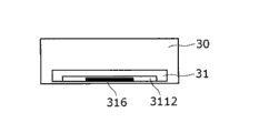
In addition, not only on the surface identical but also the sensor part 316 that comprises temperature sensor or metal detection transducer is provided in this coil, as shown in Figure 5 with the coil that constitutes power receiver 31.
If detecting the speed of temperature or temperature rising, the temperature sensor in the auxilliary equipment surpasses given threshold value; If or the metal detection sensor is to the existence of the metal between power transmitter and the receiver, then control part 317 is implemented control to prevent problematic auxilliary equipment received power.
For example, control part 317 control load modulation circuits 318, thus come the power controlling state through modulation load.Then, control part 317 is implemented control, makes to detect external object by the reflection test section 212 notice power transmitters 21 of transmitter 21.
< 4. another ios dhcp sample configuration IOS DHCP of power receiver >
Should be noted that acceptance division 314 can be substituted by Department of Communication Force shown in Figure 6 319, thereby control part 317 can notify power transmitter 21 to detect unusually through radio communication.
In the case, working load modulation circuit not.
As stated; In this embodiment, each in the auxilliary equipment 30 comprises the temperature sensor of the speed that the temperature that is applicable between detection power transmitter and the receiver or temperature rise or is applicable to the existence or the non-existent metal detection transducer of the metal (external object) between detection power transmitter and the receiver.In the case, not only with the coil similar face that constitutes power receiver 31 on but also the sensor part 316 as temperature or metal detection transducer is provided in this coil.
Between wireless (noncontact) charge period; Shown in Fig. 7 A and Fig. 7 B; If at the power transmitter that comprises main equipment 20 21 and comprise in the space between the power receiver 31 of auxilliary equipment 30 and have external object (metal) 40 that such as coin or key etc., then following situation can produce.
That is to say, because external object 40 is exposed to the high-intensity magnetic field that distributes between power transmitter and the receiver, so externally generate eddy current in the object 40.This causes the temperature of external object 40 to rise, if do not take some countermeasures then the continuous generation that produces heat possibly.
In this embodiment, for this reason, each in the auxilliary equipment 30 can notify the non-contact charge of the auxilliary equipment of main equipment to being discussed correctly still to carry out improperly through communication or load-modulate.
Then; If detecting the speed of temperature or temperature rising, the temperature sensor in the auxilliary equipment 30 surpasses given threshold value; If or the metal detection sensor then prevents auxilliary equipment 30 received powers of discussing to the existence of the metal (external object) 40 between power transmitter and the receiver.
On the other hand, through communication or load-modulate, main equipment 20 can find that the wireless charging of auxilliary equipment 30 correctly still carries out improperly.
Then, if through in the auxilliary equipment 30 of wireless charging any by charging correctly, then main equipment 20 can stop the providing of the power of the auxilliary equipment discussed, and power is offered in addition auxilliary equipment 30.Under the situation that does not have any auxilliary equipment that can be used for received power, main equipment 20 also can stop power transmission itself.
This makes the heating of the external object 40 can prevent to exist between power transmitter and the receiver.
If on the main equipment 20 but be not in the space (Fig. 7 A and Fig. 7 B) between power transmitter and arbitrary receiver external object 50 to be provided, the magnetic field between obvious specific power transmitter in the magnetic field that then distributes in this space and the receiver more a little less than.Therefore, the temperature of external object 50 will only rise a little.As a result, when arranging as stated external object can to heat be unlikely.
Should be noted that various types of transducers can be used as temperature sensor.These not only comprise be applicable to through with the temperature sensor (such as electro-hot regulator, thermocouple and condensate temperature sensor etc.) of its temperature of external object contact detection, but also comprise because the various geometries of auxilliary equipment are used the non-contact sensor of the infrared radiation that for example can measure temperature and directly not contact with external object.
In addition, each in the auxilliary equipment 30 can comprise not only one but a plurality of temperature or metal detection transducer.In addition, each in the auxilliary equipment 30 can comprise temperature sensor and metal detection transducer the two.
In addition, temperature or metal detection transducer not only can be included in each in the auxilliary equipment 30 but also be included in the main equipment 20.
Fig. 2 or Fig. 6 illustrate when with noncontact and time division way during to a plurality of power receivers charging according to the ios dhcp sample configuration IOS DHCP of the external object detection system of above embodiment.
As stated, Fig. 2 illustrates the example of the external object detection system of working load modulation, and Fig. 6 illustrates the example of the external object detection system of using communication.
In example shown in Figure 2, as the result of the load-modulate on the power receiver side, the change of the testing result of the reflection test section 212 on the power transmitter side shows.This permission power transmitter 21 is found to need not from any information of power receiver 31 transmission about the message of the state of power receiver 31.
At this, for example, switch SW 1 can be included in the MOSFET (mos field effect transistor) that the conduction type aspect differs from one another with SW2, but is not limited thereto.
< 5. preventing the ios dhcp sample configuration IOS DHCP of auxilliary equipment received power >
In this embodiment, can realize the aforesaid ability that prevents auxilliary equipment received power through switching Fig. 2 or switch SW 2 shown in Figure 6.
To this example be described with reference to the sketch map shown in Fig. 8, Fig. 9, Figure 10 and Figure 11.
Fig. 8 illustrates the transmission of power transmitter and receiver and the ios dhcp sample configuration IOS DHCP of acceptance division.
In Fig. 8, power sending part 211 comprises resonance coil 2112 (be power send coil) thereby and connects with coil and can realize the resonant capacitor C21 of series resonance in given frequency.
On the other hand, power acceptance division 311 comprises resonance coil 3112 (being the power receiving coil) thereby and can realize the resonant capacitor C31 of parallel resonance with coils from parallel connection of coils with the identical or approaching frequency of the frequency of power sending part 211.Though should be noted that and use the above ios dhcp sample configuration IOS DHCP of describing will provide description below, the power sending part not necessarily must be a series resonant circuit, the power acceptance division not necessarily must be an antiresonant circuit.The power sending part can be an antiresonant circuit, and the power acceptance division can be a series resonant circuit.
On the other hand, we suppose on the power transmitter side impedance and the impedance on the power receiver side respectively very or better coupling formerly with the impedance of the portion of following stages.This configuration allows valid wireless (noncontact) charging.
Therefore, add the resonant capacitor C32 with enough big electrostatic capacitance if use switch SW as shown in Figure 92 connects capacitor, then the resonance frequency on the power receiver side obviously changes, and therefore makes to stop wireless (noncontact) charging.Perhaps, if resonant capacitor C31 comprises a plurality of capacitors, then can change the resonance frequency on the power receiver side significantly through becoming idle mode diverter switch with in a plurality of capacitors some.This also makes and possibly stop wireless (noncontact) charging.
Perhaps, can prevent that through mode diverter switch resonance from occurring in the power acceptance division 311 with the resonance range that breaks off power acceptance division 311 shown in figure 10.This makes possibly stop non-contact charge.
In addition, shown in figure 11, through adding extra resistance R31 to the mode diverter switch of power acceptance division 311, because the change of the impedance on the power receiver side and non-Satisfying Matching Conditions.This makes and possibly stop wireless (noncontact) charging.
As stated, this embodiment provides following beneficial effect.
Carrying out under the situation of non-contact charge to a plurality of auxilliary equipment from single main equipment; If through in main equipment, providing temperature sensor to prevent the heating between main equipment and the auxilliary equipment; Then use this temperature sensor of unlimited amount, possibly cause very high cost.In addition, might feed efficient can reduce.
In this embodiment, owing to as required only in a plurality of auxilliary equipment rather than a lot of temperature or other transducer be provided in main equipment, therefore avoid heating with the transducer of minimum number.
This compared with prior art provides obviously less cost, therefore makes the reduction of feed efficient minimum.
The theme that the present invention comprises is involved in disclosed theme among the japanese priority patent application JP2010-181246 that was submitted to Japan Patent office on August 13rd, 2010, and its complete content is herein incorporated by reference.
It should be appreciated by those skilled in the art that and various modifications, combination, son combination and alternative to occur according to design requirement and other factors, as long as they are in the scope of accompanying claims and equivalents thereof.
Claims (11)
1. wireless charging system comprises:
Main equipment comprises being configured to the power transmitter of transmitted power wirelessly; And
Auxilliary equipment comprises the power receiver that is configured to receive the power that wirelessly sends from said power transmitter, wherein,
Said auxilliary equipment also comprises and is configured to detect any unusual transducer in the power transfer path between said power transmitter and said power receiver.
2. wireless charging system as claimed in claim 1, wherein,
In said main equipment and the said auxilliary equipment each all comprises and is configured to the control part that the testing result based on the transducer of said auxilliary equipment stops the power between said power transmitter and the said power receiver to send and receive.
3. wireless charging system as claimed in claim 2, wherein,
Said main equipment comprises following control part: this control part is configured to apply control so that power is offered a plurality of auxilliary equipment that each all comprises said power receiver simultaneously or sequentially.
4. wireless charging system as claimed in claim 3, wherein,
Said main equipment comprises following control part: by the sensor in the said auxilliary equipment to sending and receive under the relevant unusual situation with power; This control part can stop detecting that unusual auxilliary equipment provides power and to other auxilliary equipment power is provided, and can under the situation that does not have any auxilliary equipment that can be used for received power, stop power transmission itself.
5. wireless charging system as claimed in claim 4, wherein,
Said auxilliary equipment comprises following control part: thus this control part is configured to stoping said auxilliary equipment received power by the sensor in the said auxilliary equipment to sending and receive with power to apply under the relevant unusual situation to control.
6. wireless charging system as claimed in claim 5, wherein,
The control part of said auxilliary equipment can notify the non-contact charge of the said auxilliary equipment of said main equipment correctly still to carry out improperly through communication or load-modulate.
7. wireless charging system as claimed in claim 6, wherein,
The control part of said main equipment can find that the non-contact charge of said auxilliary equipment correctly still carries out improperly through said communication or load-modulate.
8. wireless charging system as claimed in claim 1, wherein,
Said transducer not only is arranged on the surface identical with the coil that constitutes said power receiver, but also is arranged in this coil.
9. wireless charging system as claimed in claim 1, wherein,
Not only in said auxilliary equipment but also in said main equipment, transducer is set, to detect any unusual in the power transfer path between said power transmitter and the said power receiver.
10. wireless charging system as claimed in claim 1, wherein,
Said transducer is to be configured to detect the temperature sensor of the speed that temperature or temperature between said power transmitter and the said power receiver rise or to be configured to detect the metal detection transducer that between said power transmitter and said power receiver, whether has external object.
11. wireless charging system as claimed in claim 10, wherein,
Said transducer is contact or non-contact sensor.
Applications Claiming Priority (2)
| Application Number | Priority Date | Filing Date | Title |
|---|---|---|---|
| JP2010-181246 | 2010-08-13 | ||
| JP2010181246A JP2012044735A (en) | 2010-08-13 | 2010-08-13 | Wireless charging system |
Publications (1)
| Publication Number | Publication Date |
|---|---|
| CN102377224A true CN102377224A (en) | 2012-03-14 |
Family
ID=45564342
Family Applications (1)
| Application Number | Title | Priority Date | Filing Date |
|---|---|---|---|
| CN2011102277725A Pending CN102377224A (en) | 2010-08-13 | 2011-08-05 | Wireless charging system |
Country Status (3)
| Country | Link |
|---|---|
| US (1) | US20120038317A1 (en) |
| JP (1) | JP2012044735A (en) |
| CN (1) | CN102377224A (en) |
Cited By (8)
| Publication number | Priority date | Publication date | Assignee | Title |
|---|---|---|---|---|
| CN102944259A (en) * | 2012-10-25 | 2013-02-27 | 天津大学 | Wireless passive measuring device |
| CN103368274A (en) * | 2012-03-26 | 2013-10-23 | Lg伊诺特有限公司 | Mobile terminal and power control method thereof |
| CN103852631A (en) * | 2014-01-11 | 2014-06-11 | 深圳市普林泰克科技有限公司 | Algorithm for indirectly detecting metal foreign bodies for wireless charger |
| CN104428972A (en) * | 2012-07-13 | 2015-03-18 | 高通股份有限公司 | Systems, methods, and apparatus for small device wireless charging modes |
| CN104520136A (en) * | 2012-08-07 | 2015-04-15 | 宝马股份公司 | Monitoring for foreign bodies during inductive charging |
| CN105515617A (en) * | 2014-10-08 | 2016-04-20 | 三星电子株式会社 | Apparatus and method for transmitting/receiving PTU presence information in wireless charging network |
| CN105308829B (en) * | 2013-06-19 | 2018-08-24 | 瑞萨电子株式会社 | Power transmitting device, contactless power supply system and control method |
| CN109672272A (en) * | 2017-10-13 | 2019-04-23 | 中惠创智(深圳)无线供电技术有限公司 | A kind of wireless power supply system and its Superficial Foreign Body detection device |
Families Citing this family (73)
| Publication number | Priority date | Publication date | Assignee | Title |
|---|---|---|---|---|
| US9413197B2 (en) * | 2010-05-31 | 2016-08-09 | Fu Da Tong Technology Co., Ltd. | Inductive power supply system and intruding metal detection method thereof |
| JP5395018B2 (en) * | 2010-09-07 | 2014-01-22 | 日本電信電話株式会社 | Resonant type wireless power transmission device |
| JP6014041B2 (en) | 2010-10-15 | 2016-10-25 | シーレイト リミテッド ライアビリティー カンパニーSearete Llc | Surface scattering antenna |
| JP2012143092A (en) * | 2011-01-04 | 2012-07-26 | Kimitake Utsunomiya | Charging ac adapter |
| JP5879748B2 (en) | 2011-05-27 | 2016-03-08 | 日産自動車株式会社 | Non-contact power supply device, vehicle and non-contact power supply system |
| JP5793963B2 (en) * | 2011-05-27 | 2015-10-14 | 日産自動車株式会社 | Non-contact power feeding device |
| JP5840886B2 (en) * | 2011-07-25 | 2016-01-06 | ソニー株式会社 | Detection device, power reception device, power transmission device, non-contact power transmission system, and detection method |
| US9806537B2 (en) | 2011-12-15 | 2017-10-31 | Samsung Electronics Co., Ltd | Apparatus and method for determining whether a power receiver is removed from the apparatus |
| JP2015084608A (en) * | 2012-02-09 | 2015-04-30 | 三菱電機株式会社 | Wireless power feeding system, power transmission device, and power transmission method |
| TWI587597B (en) * | 2012-02-17 | 2017-06-11 | Lg伊諾特股份有限公司 | Wireless power transmitter, wireless power receiver, and power transmission method of wireless power transmitting system |
| US9673867B2 (en) | 2012-03-14 | 2017-06-06 | Semiconductor Energy Laboratory Co., Ltd. | Power transmission device and power feeding system |
| JP5986404B2 (en) * | 2012-03-21 | 2016-09-06 | アイホン株式会社 | Intercom system |
| EP2833510B1 (en) * | 2012-03-28 | 2018-01-03 | Panasonic Intellectual Property Management Co., Ltd. | Power supply apparatus |
| KR101844422B1 (en) * | 2012-04-19 | 2018-04-03 | 삼성전자주식회사 | Apparatus and method for wireless energy transmission and apparatus wireless energy reception |
| KR102074475B1 (en) | 2012-07-10 | 2020-02-06 | 지이 하이브리드 테크놀로지스, 엘엘씨 | Apparatus and method for detecting foreign object in wireless power transmitting system |
| US9467002B2 (en) | 2012-07-19 | 2016-10-11 | Ford Global Technologies, Llc | Vehicle charging system |
| US20140021912A1 (en) * | 2012-07-19 | 2014-01-23 | Ford Global Technologies, Llc | Vehicle battery charging system and method |
| US10773596B2 (en) | 2012-07-19 | 2020-09-15 | Ford Global Technologies, Llc | Vehicle battery charging system and method |
| JP2014030288A (en) * | 2012-07-31 | 2014-02-13 | Sony Corp | Power supply device and power supply system |
| JP2015195633A (en) * | 2012-08-23 | 2015-11-05 | パナソニック株式会社 | Non-contact power feeding device |
| JP6152629B2 (en) * | 2012-08-24 | 2017-06-28 | パナソニックIpマネジメント株式会社 | Non-contact power receiving apparatus and non-contact power feeding system |
| KR102080096B1 (en) * | 2012-10-19 | 2020-04-14 | 삼성전자주식회사 | Wireless power transmitter, wireless power receiver and method for transmitting a emergency information in wireless power network |
| WO2014103222A1 (en) * | 2012-12-27 | 2014-07-03 | 株式会社デンソー | Metal object detection device |
| US9755436B2 (en) * | 2013-02-14 | 2017-09-05 | Toyota Jidosha Kabushiki Kaisha | Power receiving device and power transmitting device |
| KR102113258B1 (en) * | 2013-02-15 | 2020-05-20 | 삼성전자주식회사 | Display Apparatus and Wireless Charging System including Display Apparatus |
| EP2961036B1 (en) * | 2013-02-19 | 2019-08-21 | Panasonic Intellectual Property Management Co., Ltd. | Foreign object detection device, foreign object detection method, and non-contact charging system |
| JP6188351B2 (en) | 2013-03-01 | 2017-08-30 | キヤノン株式会社 | Power supply apparatus, power supply apparatus control method, and program |
| US9667084B2 (en) * | 2013-03-13 | 2017-05-30 | Nxp Usa, Inc. | Wireless charging systems, devices, and methods |
| KR102051682B1 (en) | 2013-03-15 | 2019-12-03 | 지이 하이브리드 테크놀로지스, 엘엘씨 | Apparatus and method for detecting foreign object in wireless power transmitting system |
| US9385435B2 (en) | 2013-03-15 | 2016-07-05 | The Invention Science Fund I, Llc | Surface scattering antenna improvements |
| TWI539712B (en) * | 2013-04-12 | 2016-06-21 | 崇貿科技股份有限公司 | Method and apparatus for controlling wireless induction power supply |
| JP2014220970A (en) | 2013-05-10 | 2014-11-20 | キヤノン株式会社 | Transmission apparatus and method, and program |
| JP6116361B2 (en) * | 2013-05-16 | 2017-04-19 | キヤノン株式会社 | Power transmission system, power receiving apparatus, control method, and program |
| WO2015005935A1 (en) | 2013-07-12 | 2015-01-15 | Schneider Electric USA, Inc. | Method and device for foreign object detection in induction electric charger |
| EP2875586B2 (en) * | 2013-08-07 | 2020-12-23 | Koninklijke Philips N.V. | Wireless inductive power transfer |
| KR20150021285A (en) * | 2013-08-20 | 2015-03-02 | 엘지이노텍 주식회사 | Wireless power receiving device |
| JP6015608B2 (en) * | 2013-09-19 | 2016-10-26 | 株式会社豊田自動織機 | Power receiving device and non-contact power transmission device |
| US9923271B2 (en) | 2013-10-21 | 2018-03-20 | Elwha Llc | Antenna system having at least two apertures facilitating reduction of interfering signals |
| KR20150050027A (en) * | 2013-10-31 | 2015-05-08 | 삼성전기주식회사 | Wireless charging device and controlling method thereof |
| JP6004122B2 (en) * | 2013-12-05 | 2016-10-05 | 株式会社村田製作所 | Power receiving device and power transmission system |
| US9935375B2 (en) | 2013-12-10 | 2018-04-03 | Elwha Llc | Surface scattering reflector antenna |
| US9825358B2 (en) * | 2013-12-17 | 2017-11-21 | Elwha Llc | System wirelessly transferring power to a target device over a modeled transmission pathway without exceeding a radiation limit for human beings |
| JP6223471B2 (en) * | 2013-12-26 | 2017-11-01 | 三菱電機エンジニアリング株式会社 | Resonant transmission power supply apparatus and resonant transmission power supply system |
| WO2015097810A1 (en) * | 2013-12-26 | 2015-07-02 | 三菱電機エンジニアリング株式会社 | Resonant power-transfer system and resonant power-transmission device |
| WO2015113466A1 (en) * | 2014-01-28 | 2015-08-06 | 广东欧珀移动通信有限公司 | Power adapter, terminal, and method for processing exception of charging loop |
| CN103762691B (en) | 2014-01-28 | 2015-12-23 | 广东欧珀移动通信有限公司 | Battery charger and cell charge protection control method |
| CN103779907B (en) | 2014-01-28 | 2016-11-23 | 广东欧珀移动通信有限公司 | Terminal and battery charging control device and method thereof |
| US20150229135A1 (en) * | 2014-02-10 | 2015-08-13 | Shahar Porat | Wireless load modulation |
| KR102147550B1 (en) * | 2014-02-17 | 2020-08-24 | 엘에스전선 주식회사 | Wireless power transmission apparatus, wireless power reception apparatus, wireless power transmission apparatus system, and wireless power transmission method |
| US9843103B2 (en) | 2014-03-26 | 2017-12-12 | Elwha Llc | Methods and apparatus for controlling a surface scattering antenna array |
| US9853361B2 (en) | 2014-05-02 | 2017-12-26 | The Invention Science Fund I Llc | Surface scattering antennas with lumped elements |
| US9882288B2 (en) | 2014-05-02 | 2018-01-30 | The Invention Science Fund I Llc | Slotted surface scattering antennas |
| US10446903B2 (en) | 2014-05-02 | 2019-10-15 | The Invention Science Fund I, Llc | Curved surface scattering antennas |
| KR101891426B1 (en) | 2014-05-20 | 2018-08-24 | 후지쯔 가부시끼가이샤 | Wireless power transmission control method and wireless power transmission system |
| US9829599B2 (en) | 2015-03-23 | 2017-11-28 | Schneider Electric USA, Inc. | Sensor and method for foreign object detection in induction electric charger |
| CN106160031B (en) * | 2015-03-25 | 2019-08-27 | 联想(北京)有限公司 | Electronic equipment and information processing method |
| WO2016205396A1 (en) | 2015-06-15 | 2016-12-22 | Black Eric J | Methods and systems for communication with beamforming antennas |
| KR20170021011A (en) * | 2015-08-17 | 2017-02-27 | 엘지이노텍 주식회사 | Wireless Power Transmitter And Vehicle Control Unit Connected To The Same |
| WO2017043546A1 (en) | 2015-09-09 | 2017-03-16 | 株式会社村田製作所 | Wireless sensor |
| JP6659315B2 (en) * | 2015-11-16 | 2020-03-04 | 東芝テック株式会社 | Electronics |
| US10879705B2 (en) | 2016-08-26 | 2020-12-29 | Nucurrent, Inc. | Wireless connector receiver module with an electrical connector |
| US20180090973A1 (en) | 2016-09-23 | 2018-03-29 | Apple Inc. | Wireless charging mat with a transmitter coil arrangement including inner and outer coils having different structures |
| US10361481B2 (en) | 2016-10-31 | 2019-07-23 | The Invention Science Fund I, Llc | Surface scattering antennas with frequency shifting for mutual coupling mitigation |
| EP3346581B1 (en) * | 2017-01-04 | 2023-06-14 | LG Electronics Inc. | Wireless charger for mobile terminal in vehicle |
| CN110999026B (en) | 2017-08-01 | 2025-08-15 | 福特全球技术公司 | Wireless charger enabled |
| CN107332363B (en) * | 2017-08-21 | 2020-08-25 | 京东方科技集团股份有限公司 | Wireless charging system and control method thereof |
| KR102509314B1 (en) * | 2018-05-16 | 2023-03-14 | 엘지이노텍 주식회사 | Method and Apparatus for Controlling Wireless Power Transmission |
| KR102647156B1 (en) * | 2018-10-15 | 2024-03-14 | 삼성전자 주식회사 | Electronic device and method for wire and wireless charging in electronic device |
| US11881730B2 (en) * | 2019-09-06 | 2024-01-23 | Google Llc | Wireless charging using time-division multiplexing |
| KR102272743B1 (en) * | 2019-11-25 | 2021-07-07 | 지이 하이브리드 테크놀로지스, 엘엘씨 | Apparatus and method for detecting foreign object in wireless power transmitting system |
| KR102136667B1 (en) * | 2020-01-30 | 2020-07-24 | 지이 하이브리드 테크놀로지스, 엘엘씨 | Apparatus and method for detecting foreign object in wireless power transmitting system |
| US20210291009A1 (en) * | 2020-03-22 | 2021-09-23 | Kevin Paganini | Intelligent exercise mats, accessories, assemblies, systems, and methods of using the same |
| EP4164090A1 (en) | 2021-10-06 | 2023-04-12 | ABB E-mobility B.V. | A method for a foreign object detection in a contactless charging system |
Family Cites Families (6)
| Publication number | Priority date | Publication date | Assignee | Title |
|---|---|---|---|---|
| DE10007777A1 (en) * | 2000-02-21 | 2001-09-20 | Magnet Motor Gmbh | Permanent magnet excited electrical machine and method for operating such a machine |
| AU2008339692B2 (en) * | 2007-12-21 | 2014-08-21 | Access Business Group International Llc | Circuitry for inductive power transfer |
| US7986059B2 (en) * | 2008-01-04 | 2011-07-26 | Pure Energy Solutions, Inc. | Device cover with embedded power receiver |
| US20100277121A1 (en) * | 2008-09-27 | 2010-11-04 | Hall Katherine L | Wireless energy transfer between a source and a vehicle |
| JP5417907B2 (en) * | 2009-03-09 | 2014-02-19 | セイコーエプソン株式会社 | Power transmission control device, power transmission device, power reception control device, power reception device, electronic device, and contactless power transmission system |
| US8247749B2 (en) * | 2009-07-04 | 2012-08-21 | Inductoheat, Inc. | Application of electric induction energy for manufacture of irregularly shaped shafts with cylindrical components including non-unitarily forged crankshafts and camshafts |
-
2010
- 2010-08-13 JP JP2010181246A patent/JP2012044735A/en active Pending
-
2011
- 2011-08-04 US US13/197,842 patent/US20120038317A1/en not_active Abandoned
- 2011-08-05 CN CN2011102277725A patent/CN102377224A/en active Pending
Cited By (15)
| Publication number | Priority date | Publication date | Assignee | Title |
|---|---|---|---|---|
| US9054747B2 (en) | 2012-03-26 | 2015-06-09 | Lg Innotek Co., Ltd. | Mobile terminal and power control method thereof |
| CN103368274A (en) * | 2012-03-26 | 2013-10-23 | Lg伊诺特有限公司 | Mobile terminal and power control method thereof |
| CN103368274B (en) * | 2012-03-26 | 2016-01-20 | Lg伊诺特有限公司 | Mobile terminal and electrical control method thereof |
| CN104428972A (en) * | 2012-07-13 | 2015-03-18 | 高通股份有限公司 | Systems, methods, and apparatus for small device wireless charging modes |
| CN104428972B (en) * | 2012-07-13 | 2017-04-12 | 高通股份有限公司 | Systems, methods, and apparatus for small device wireless charging modes |
| CN104520136A (en) * | 2012-08-07 | 2015-04-15 | 宝马股份公司 | Monitoring for foreign bodies during inductive charging |
| CN104520136B (en) * | 2012-08-07 | 2017-01-18 | 宝马股份公司 | Monitoring for foreign bodies during inductive charging |
| US9676286B2 (en) | 2012-08-07 | 2017-06-13 | Bayerische Motoren Werke Aktiengesellschaft | Monitoring for foreign bodies during inductive charging |
| CN102944259B (en) * | 2012-10-25 | 2015-05-20 | 天津大学 | Wireless passive measuring device |
| CN102944259A (en) * | 2012-10-25 | 2013-02-27 | 天津大学 | Wireless passive measuring device |
| CN105308829B (en) * | 2013-06-19 | 2018-08-24 | 瑞萨电子株式会社 | Power transmitting device, contactless power supply system and control method |
| CN103852631A (en) * | 2014-01-11 | 2014-06-11 | 深圳市普林泰克科技有限公司 | Algorithm for indirectly detecting metal foreign bodies for wireless charger |
| CN105515617A (en) * | 2014-10-08 | 2016-04-20 | 三星电子株式会社 | Apparatus and method for transmitting/receiving PTU presence information in wireless charging network |
| CN105515617B (en) * | 2014-10-08 | 2021-05-11 | 三星电子株式会社 | Apparatus and method for transmitting/receiving PTU presence information in wireless charging network |
| CN109672272A (en) * | 2017-10-13 | 2019-04-23 | 中惠创智(深圳)无线供电技术有限公司 | A kind of wireless power supply system and its Superficial Foreign Body detection device |
Also Published As
| Publication number | Publication date |
|---|---|
| JP2012044735A (en) | 2012-03-01 |
| US20120038317A1 (en) | 2012-02-16 |
Similar Documents
| Publication | Publication Date | Title |
|---|---|---|
| CN102377224A (en) | Wireless charging system | |
| US11303135B2 (en) | Wireless power transmitter for excluding cross-connected wireless power receiver and method for controlling the same | |
| US12413103B2 (en) | Apparatus and method for detecting foreign objects in wireless power transmission system | |
| US9472983B2 (en) | Wireless power transmitter and method for controlling same | |
| US10587123B2 (en) | Wireless power transmitter for excluding cross-connected wireless power receiver and method for controlling the same | |
| US10224761B2 (en) | Method for controlling power in a wireless power transmission apparatus and a wireless power transmission apparatus | |
| US8541975B2 (en) | System and method for efficient wireless charging of a mobile terminal | |
| CN102694425B (en) | Wireless power receiving apparatus and power control method thereof | |
| CN103959598B (en) | Wireless power transmitter, wireless power repeater and wireless power transmission method | |
| KR101667725B1 (en) | Wireless power transmitter and method for controlling the same | |
| US8390250B2 (en) | Non-contact charge and communication system | |
| US20120313447A1 (en) | Method of performing bidirectional communication between transmitter and receiver in wireless power transmission/reception system, the transmitter, and the receiver | |
| EP2634892B1 (en) | Wireless power receiver and controlling method thereof | |
| US20160043590A1 (en) | Wireless power transfer system and wireless charging system | |
| US20150214748A1 (en) | Wireless power supply scheme capable of dynamically adjusting output power of wireless power transmitter according to voltage/current/power information of portable electronic device to be charged | |
| JP6279452B2 (en) | Non-contact power transmission device | |
| CN109104885A (en) | Wireless charging system and its equipment | |
| CN108450042A (en) | Wireless charging device, wireless power transmission method thereby, and recording medium therefor | |
| CN110692177A (en) | Wireless charging device, receiver device and operation method thereof | |
| KR20150078428A (en) | Power charging apparatus and battery apparatus | |
| CN104247205A (en) | Power supply device and power supply receiving system | |
| CN110999030B (en) | Wireless charging device, receiver device and related methods | |
| CN106471709B (en) | Wireless power transmission system | |
| JP2010284066A (en) | Communication device, communication terminal and communication system | |
| KR101034740B1 (en) | Wireless Power Transmission System and Method |
Legal Events
| Date | Code | Title | Description |
|---|---|---|---|
| C06 | Publication | ||
| PB01 | Publication | ||
| C02 | Deemed withdrawal of patent application after publication (patent law 2001) | ||
| WD01 | Invention patent application deemed withdrawn after publication |
Application publication date: 20120314 |