CN102365522A - Three-dimensional shape measuring device, three-dimensional shape measuring method, and three-dimensional shape measuring program - Google Patents
Three-dimensional shape measuring device, three-dimensional shape measuring method, and three-dimensional shape measuring program Download PDFInfo
- Publication number
- CN102365522A CN102365522A CN2010800141052A CN201080014105A CN102365522A CN 102365522 A CN102365522 A CN 102365522A CN 2010800141052 A CN2010800141052 A CN 2010800141052A CN 201080014105 A CN201080014105 A CN 201080014105A CN 102365522 A CN102365522 A CN 102365522A
- Authority
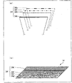
- CN
- China
- Prior art keywords
- height
- measurement
- measurement object
- phase
- unit
- Prior art date
- Legal status (The legal status is an assumption and is not a legal conclusion. Google has not performed a legal analysis and makes no representation as to the accuracy of the status listed.)
- Granted
Links
Images




Classifications
-
- G—PHYSICS
- G01—MEASURING; TESTING
- G01B—MEASURING LENGTH, THICKNESS OR SIMILAR LINEAR DIMENSIONS; MEASURING ANGLES; MEASURING AREAS; MEASURING IRREGULARITIES OF SURFACES OR CONTOURS
- G01B11/00—Measuring arrangements characterised by the use of optical techniques
- G01B11/24—Measuring arrangements characterised by the use of optical techniques for measuring contours or curvatures
- G01B11/25—Measuring arrangements characterised by the use of optical techniques for measuring contours or curvatures by projecting a pattern, e.g. one or more lines, moiré fringes on the object
-
- G—PHYSICS
- G01—MEASURING; TESTING
- G01B—MEASURING LENGTH, THICKNESS OR SIMILAR LINEAR DIMENSIONS; MEASURING ANGLES; MEASURING AREAS; MEASURING IRREGULARITIES OF SURFACES OR CONTOURS
- G01B11/00—Measuring arrangements characterised by the use of optical techniques
- G01B11/24—Measuring arrangements characterised by the use of optical techniques for measuring contours or curvatures
- G01B11/25—Measuring arrangements characterised by the use of optical techniques for measuring contours or curvatures by projecting a pattern, e.g. one or more lines, moiré fringes on the object
- G01B11/2518—Projection by scanning of the object
- G01B11/2522—Projection by scanning of the object the position of the object changing and being recorded
-
- G—PHYSICS
- G01—MEASURING; TESTING
- G01B—MEASURING LENGTH, THICKNESS OR SIMILAR LINEAR DIMENSIONS; MEASURING ANGLES; MEASURING AREAS; MEASURING IRREGULARITIES OF SURFACES OR CONTOURS
- G01B11/00—Measuring arrangements characterised by the use of optical techniques
- G01B11/24—Measuring arrangements characterised by the use of optical techniques for measuring contours or curvatures
- G01B11/25—Measuring arrangements characterised by the use of optical techniques for measuring contours or curvatures by projecting a pattern, e.g. one or more lines, moiré fringes on the object
- G01B11/2518—Projection by scanning of the object
- G01B11/2527—Projection by scanning of the object with phase change by in-plane movement of the patern
Landscapes
- Engineering & Computer Science (AREA)
- Computer Vision & Pattern Recognition (AREA)
- Physics & Mathematics (AREA)
- General Physics & Mathematics (AREA)
- Length Measuring Devices By Optical Means (AREA)
Abstract
一种在维持计测范围的同时简便扩展可计测高度的三维形状计测系统,对投影到计测对象上的亮度因位置而周期性变化的光图案进行分析来计测上述计测对象的三维形状,在三维形状计测系统中,计测对象安装在具有计测对象的高度基准面的安装台上,由计测头将光图案投影到计测对象及基准面上,由移位部使计测头向高度方向移位。由相位计算部(75)计算拍摄到的图像中的某个像素的光图案的相位,由高度计算部(77)基于计算出的相位来计算计测对象的高度,由进给量计算部(78)基于计算出的高度来计算使移位部应当移位的移位量。高度计算部(77)基于由相位计算部(75)计算出的相位来计算高度,并基于移位量来修正计算出的高度,由此计算计测对象的高度。

A three-dimensional shape measurement system that can easily expand the measurable height while maintaining the measurement range. The system measures the three-dimensional shape of the object by analyzing a light pattern whose brightness changes periodically with position when projected onto the object. In the three-dimensional shape measurement system, the object is mounted on a mounting platform with a height reference surface. A measuring head projects a light pattern onto the object and the reference surface. A shifting unit shifts the measuring head in the height direction. A phase calculation unit (75) calculates the phase of the light pattern of a pixel in the captured image. A height calculation unit (77) calculates the height of the object based on the calculated phase. A feed calculation unit (78) calculates the shift amount that the shifting unit should shift based on the calculated height. The height calculation unit (77) calculates the height based on the phase calculated by the phase calculation unit (75) and corrects the calculated height based on the shift amount, thereby calculating the height of the object.
Description
技术领域 technical field
本发明涉及通过对投影到计测对象上的光图案(photo pattern)进行分析,来计测计测对象的三维形状的三维形状计测装置、三维形状计测方法及三维形状计测程序。The present invention relates to a three-dimensional shape measurement device, a three-dimensional shape measurement method, and a three-dimensional shape measurement program for measuring the three-dimensional shape of a measurement object by analyzing a photo pattern projected on the measurement object.
背景技术 Background technique
就通过图像分析得出对象物的三维形状信息的单元来说,存在这样的方法:将光图案投影到存在于规定拍摄视场内的计测对象上,对根据计测对象的三维形状而变形的光图案的变形量进行分析。就具有代表性的方法来说,可例举光切断法、空间编码法及条纹分析法等。这些方法全部都是基于三角测量原理的方法,其中,关于条纹分析法,提出了空间条纹分析、时间条纹分析等多种方法,并视为能够得到高计测精度的方法(专利文献1~3,非专利文献1)。As for the unit that obtains the three-dimensional shape information of the object through image analysis, there is a method of projecting a light pattern onto the measurement object existing in a predetermined imaging field of view, and deforming the object according to the three-dimensional shape of the measurement object. The amount of deformation of the light pattern is analyzed. Typical methods include light cutting, spatial encoding, fringe analysis and the like. All of these methods are methods based on the principle of triangulation. Among them, as for the fringe analysis method, various methods such as spatial fringe analysis and time fringe analysis have been proposed, and are considered to be methods capable of obtaining high measurement accuracy (
在上述的方法的情况下,对光图案进行投影的投光单元、放置计测对象的平面即基准面以及拍摄计测对象的拍摄单元之间的几何学位置关系,会影响到高度位置的测定精度。参照图15对该点进行说明。In the case of the above-mentioned method, the geometric positional relationship between the light projection unit that projects the light pattern, the reference plane on which the measurement object is placed, and the imaging unit that photographs the measurement object will affect the measurement of the height position. precision. This point will be described with reference to FIG. 15 .
图15是示出了三角测量原理的图。为了简化说明,考虑利用具有与基准面P0垂直的光轴的拍摄单元Cc,来观测从基准面P0起高度为h的平面Ph。另外,假设投光单元Cp配置在从基准面P0观察时与拍摄单元Cc相同的高度上,并将光图案向基准面P0上的点O的位置进行投影。Fig. 15 is a diagram showing the principle of triangulation. To simplify the description, it is assumed that a plane Ph whose height is h from the reference plane P0 is observed by the imaging unit Cc having an optical axis perpendicular to the reference plane P0. In addition, it is assumed that the light projection unit Cp is arranged at the same height as the imaging unit Cc when viewed from the reference plane P0, and projects the light pattern to the position of the point O on the reference plane P0.
在观测与基准面P0平行且与该基准面P0分离相距距离为高度h的平面Ph的情况下,朝向点O的光图案与点P相交。此时,从拍摄单元Cc观察时,能够在从与光轴(Z轴)到相距距离PQ的位置P上观测到向基准面P0投影的光图案。该位置偏移PQ体表现为光图案的相位差。只要能够计算出相位差,就能够利用下面的公式(1)来计算高度h。The light pattern directed towards the point O intersects the point P when observing a plane Ph parallel to the reference plane P0 and separated therefrom by a distance h. At this time, when viewed from the imaging unit Cc, the light pattern projected onto the reference plane P0 can be observed at a position P at a distance PQ from the optical axis (Z axis). This position shift PQ volume appears as a phase difference of the light pattern. As long as the phase difference can be calculated, the height h can be calculated using the following formula (1).
公式1
(其中,
现有技术文献prior art literature
专利文献patent documents
专利文献1:日本公开专利公报“日本特开2002-286433号公报(2002年10月03日公开)”,Patent Document 1: Japanese Laid-Open Patent Gazette "Japanese Patent Laying-Open No. 2002-286433 (published on October 3, 2002)",
专利文献2:日本公开专利公报“日本特开2004-117186号公报(2004年04月15日公开)”,Patent Document 2: Japanese Laid-Open Patent Gazette "Japanese Patent Laying-Open No. 2004-117186 (published on April 15, 2004)",
专利文献3:日本公开专利公报“日本特开2007-114071号公报(2007年05月10日公开)”,Patent Document 3: Japanese Laid-Open Patent Gazette "Japanese Patent Laying-Open No. 2007-114071 (published on May 10, 2007)",
专利文献4:日本公开专利公报“日本特开2002-214147号公报(2002年07月31日公开)”,Patent Document 4: Japanese Laid-Open Patent Gazette "Japanese Patent Laying-Open No. 2002-214147 (published on July 31, 2002)",
专利文献5:日本公开专利公报“日本特开2005-300512号公报(2005年10月27日公开)”。Patent document 5: Japanese laid-open patent publication "Japanese Patent Laid-Open No. 2005-300512 (published on October 27, 2005)".
非专利文献non-patent literature
非专利文献1:“藤垣”等人,“基于多个线性传感器的连续物体形状计测的平行光格子投影方法”,精密工学会秋季大会学术演讲会演讲论文集pp.1061-1062,2004。Non-Patent Document 1: "Fujigaki" et al., "Parallel Light Lattice Projection Method for Continuous Object Shape Measurement Using Multiple Linear Sensors", Proceedings of Lectures at the Autumn Conference of the Society of Precision Engineering, pp.1061-1062, 2004 .
发明内容 Contents of the invention
发明要解决的问题The problem to be solved by the invention
然而,一般来说,将原来的相位差除以2π而得到的余数,来作为计算出的上述相位差。因此,能够计测的相位差的范围限于2π,导致能够计测的高度的范围(计测范围(Range))被限制。However, generally, the remainder obtained by dividing the original phase difference by 2π is used as the calculated phase difference. Therefore, the range of the phase difference that can be measured is limited to 2π, and the range of the height that can be measured (measurement range (Range)) is limited.
因此,提出了几个扩展能够计测的高度的方法。就一个方法来说,可例举扩大光图案的周期的方法。若扩大该周期,则与一个周期相对应的位置偏移PQ变长,从而能够扩展上述计测范围。Therefore, several methods of expanding the measurable height have been proposed. One method may, for example, be a method of enlarging the period of the light pattern. When this period is enlarged, the positional shift PQ corresponding to one period becomes longer, and the measurement range described above can be expanded.
然而,在上述方法中,若上述相位差的分辨率相同,则位置偏移PQ的分辨率(可识别的最小值)变长,导致上述高度的分辨率变长(恶化)。即,上述高度的精度降低。为了避免该问题,只要提高上述相位差的分辨率即可,但这需要高价的光学系统,且对校正费工夫。However, in the method described above, if the resolution of the phase difference is the same, the resolution of the positional offset PQ (recognizable minimum value) becomes longer, and the resolution of the height becomes longer (deteriorated). That is, the accuracy of the height described above is lowered. In order to avoid this problem, it is only necessary to increase the resolution of the above-mentioned phase difference, but this requires an expensive optical system and requires labor for correction.
就其他的方法来说,可例举利用新的移位传感器计测计测对象的大致的形状,并基于该形状来变更上述计测范围,由此扩展(增大)能够计测的高度的方法。然而,此时,需要设置新的移位传感器来进行校正,并增加用于计测的成本及工夫。As another method, it is possible to use a new displacement sensor to measure the approximate shape of the object to be measured, and to change the above-mentioned measurement range based on the shape, thereby expanding (increasing) the height that can be measured. method. However, in this case, it is necessary to install a new displacement sensor for calibration, which increases the cost and effort for measurement.
本发明是鉴于上述的问题点而做出的,其目的在于,提高一种能够在维持计测范围的同时,简便地扩展(增大)能够计测的高度的三维形状计测装置等。The present invention has been made in view of the above-mentioned problems, and an object of the present invention is to provide a three-dimensional shape measuring device and the like that can easily expand (increase) a measurable height while maintaining a measurement range.
用于解决问题的手段means of solving problems
本发明的三维形状计测装置,通过对投影到计测对象上的其亮度根据位置而周期性地变化的光图案进行分析,来计测上述计测对象的三维形状,为了解决上述问题,该三维形状计测装置特征在于,具有:安装台,其具有成为上述计测对象的高度的基准的基准面,且上述计测对象安装在该安装台上,计测头,其将上述光图案投影到上述计测对象及上述基准面上,并拍摄所投影的光图案,移位部,其使上述安装台及上述计测头这两个构件中的至少一个构件,向上述计测对象的高度方向移位,相位计算单元,其对包含在由上述计测头所拍摄的图像中的某个像素的上述光图案的相位进行计算,高度计算单元,其基于由该相位计算单元计算出的相位,来计算上述计测对象的高度,移位部控制单元,其基于由该高度计算单元计算出的上述计测对象的高度,来控制上述移位部;上述高度计算单元,基于由上述相位计算单元计算出的相位来计算高度,并基于特定移位量来修正计算出的高度,由此计算上述计测对象的高度,所述特定移位量是指,由上述移位部使上述一个构件在从上述安装台的基准面到上述计测头为止的高度范围内移位的移位量。The three-dimensional shape measuring device of the present invention measures the three-dimensional shape of the measurement object by analyzing a light pattern projected onto the measurement object whose brightness changes periodically according to the position. In order to solve the above-mentioned problems, the The three-dimensional shape measuring device is characterized by comprising: a mounting table having a reference plane serving as a reference for the height of the measurement object, and the measurement object is mounted on the mounting table; and a measuring head for projecting the light pattern to the above-mentioned measurement object and the above-mentioned reference surface, and photograph the projected light pattern, and the displacement part makes at least one of the two members of the above-mentioned installation table and the above-mentioned measurement head move to the height of the above-mentioned measurement object. a direction shift, a phase calculation unit that calculates the phase of the light pattern of a certain pixel included in the image captured by the measurement head, and a height calculation unit based on the phase calculated by the phase calculation unit , to calculate the height of the above-mentioned measurement object, the displacement part control unit, which controls the above-mentioned displacement part based on the height of the above-mentioned measurement object calculated by the height calculation unit; the above-mentioned height calculation unit, based on the calculation by the above-mentioned phase calculating the height by means of the calculated phase, and correcting the calculated height based on a specific displacement amount that makes the one member The amount of displacement within the height range from the reference plane of the mounting table to the measuring head.
另外,本发明的三维形状计测方法,应用于三维形状计测装置,该三维形状计测装置通过对投影到计测对象上的其亮度根据位置而周期性地变化的光图案进行分析,来计测上述计测对象,该三维形状计测方法的特征在于,包括:相位计算步骤,将上述光图案投影到上述计测对象和基准面上,并计算包含在由计测头拍摄到的图像中的某个像素的上述光图案的相位,其中,上述基准面是指,在安装有该计测对象的安装台上成为上述计测对象的高度的基准的基准面,上述计测头用于拍摄所投影的光图案,高度计算步骤,基于由该相位计算步骤计算出的相位,计算上述计测对象的高度,移位部控制步骤,基于由该高度计算步骤计算出的上述计测对象的高度,来使上述安装台及上述计测头这两个构件中的至少一个构件,向上述计测对象的高度方向移位;在上述高度计算步骤中,基于由上述相位计算步骤计算出的相位来计算高度,并基于特定移位量来修正计算出的高度,由此计算上述计测对象的高度,所述特定移位量是指,由上述移位部使上述一个构件在从上述安装台的基准面到上述计测头为止的高度范围内移位的移位量。In addition, the three-dimensional shape measurement method of the present invention is applied to a three-dimensional shape measurement device that analyzes a light pattern projected onto a measurement object whose luminance changes periodically depending on the position. Measuring the measurement object, the three-dimensional shape measurement method is characterized by including: a phase calculation step of projecting the light pattern onto the measurement object and the reference surface, and calculating the phase included in the image captured by the measurement head The phase of the above-mentioned light pattern in a certain pixel, wherein the above-mentioned reference plane refers to a reference plane that serves as a reference for the height of the above-mentioned measurement object on the mounting table on which the measurement object is installed, and the above-mentioned measurement head is used for The projected light pattern is photographed, the height calculation step calculates the height of the measurement object based on the phase calculated in the phase calculation step, and the displacement unit control step calculates the height of the measurement object based on the height calculation step. height, so that at least one of the two components of the above-mentioned mounting table and the above-mentioned measurement head is displaced in the height direction of the measurement object; in the above-mentioned height calculation step, based on the phase calculated by the above-mentioned phase calculation step to calculate the height, and correct the calculated height based on the specific displacement amount, which means that the above-mentioned one member is moved from the above-mentioned mounting table by the above-mentioned displacement part The amount of displacement within the height range from the reference plane to the above-mentioned measuring head.
若采用上述的结构及方法,则基于某像素的光图案的相位来计算高度,并基于由移位部使上述一个构件在从安装台的基准面到计测头为止的高度范围内移动的移位量,来修正计算出的高度,由此计算计测对象的高度。并且,基于计算出的上述计测对象的高度,使上述安装台及上述计测头这两个构件中的至少一个构件在上述计测对象的高度方向上移位。According to the above-mentioned structure and method, the height is calculated based on the phase of the light pattern of a certain pixel, and the height is calculated based on the displacement of the above-mentioned one member by the displacement part within the height range from the reference plane of the mounting table to the measuring head. To correct the calculated height, the height of the measurement object is calculated. Then, based on the calculated height of the measurement object, at least one of the two members of the mounting table and the measurement head is displaced in the height direction of the measurement object.
一般来说,为了对三维形状计测装置进行校正,能够调整从上述安装台的基准面到上述计测头为止的上述高度方向的距离(高度)。即,一般来说,在三维形状计测装置上设有用于在上述高度方向上调整上述计测头及/或上述安装台的高度调整机构。In general, in order to calibrate a three-dimensional shape measuring device, the distance (height) in the height direction from the reference plane of the mounting table to the measuring head can be adjusted. That is, in general, a three-dimensional shape measurement device is provided with a height adjustment mechanism for adjusting the measurement head and/or the mounting table in the height direction.
通过将该高度调整机构变更为移位部,能够使计测范围在上述高度方向上容易地移位,所述移位部基于上述计测对象的高度来控制上述计测头及/或上述安装台,以使该计测头及/或上述安装台在上述高度方向上移位。另外,能够与以往的校正一起进行上述移位部的校正,因而能够抑制校正工夫(耗时)增加。The measurement range can be easily displaced in the height direction by changing the height adjustment mechanism to a displacement unit that controls the measurement head and/or the attachment based on the height of the measurement object. and displace the measuring head and/or the mounting table in the height direction. In addition, since the above-mentioned correction of the displacement portion can be performed together with the conventional correction, it is possible to suppress an increase in effort (time consumption) for correction.
并且,基于由上述移位部使该计测头及/或上述安装台移位的移位量,来修正基于上述相位计算出的高度,由此能够计算出计测对象的准确高度,而不需设置用于计测高度的新传感器。从而,若采用本发明,则能够在维持上述计测范围的同时,简便地扩展可计测的高度。In addition, the height calculated based on the phase is corrected based on the amount of displacement of the measuring head and/or the mounting table by the displacement unit, whereby the accurate height of the measurement object can be calculated without A new sensor for measuring altitude needs to be installed. Therefore, according to the present invention, it is possible to easily expand the measurable height while maintaining the above-mentioned measurement range.
此外,上述计测对象可以安装在上述基准面上,也可以以与上述基准面分离的方式安装。另外,优选上述移位部使上述计测头在高度方向上移位,但也可以使上述安装台在高度方向上移位,还可以使上述计测头及上述安装台的双方在高度方向上移位。In addition, the measurement target may be attached to the reference surface, or may be attached so as to be separated from the reference surface. In addition, it is preferable that the displacement unit displaces the measuring head in the height direction, but it may also displace the mounting table in the height direction, or it may make both the measuring head and the mounting table move in the height direction. shift.
此外,能够使计算机利用三维形状计测程序来执行上述三维形状计测装置的各步骤。进而,通过将上述三维形状计测程序存储在计算机能够读取的存储介质中,能够在任意的计算机上执行上述三维形状计测程序。In addition, it is possible to cause a computer to execute each step of the above-mentioned three-dimensional shape measurement device using a three-dimensional shape measurement program. Furthermore, by storing the above-mentioned three-dimensional shape measurement program in a computer-readable storage medium, the above-mentioned three-dimensional shape measurement program can be executed on any computer.
发明效果Invention effect
如上所述,在本发明的三维形状计测装置中,通过将以往的高度调整机构变更为移位部,能够使计测范围在上述高度方向上容易地移位,且能够抑制校正工夫(耗时)的增加,并且,基于由上述移位部使计测头及/或上述安装台移位的移位量,来修正基于相位计算出的高度,能够计算出上述计测对象的准确高度,而不需设置用于计测高度的新传感器,因而实现能够在维持上述计测范围的同时简便地扩展(增大)可计测的高度的效果,其中,所述移位部用于,基于计测对象的高度来控制计测头及/或安装台,以使该计测头及/或上述安装台在上述高度方向上移位。As described above, in the three-dimensional shape measuring device of the present invention, by changing the conventional height adjustment mechanism to the displacement unit, the measurement range can be easily displaced in the above-mentioned height direction, and the calibration labor (consumption) can be suppressed. time), and by correcting the height calculated based on the phase based on the displacement amount of the measuring head and/or the mounting table by the displacement unit, the accurate height of the measurement object can be calculated, There is no need to install a new sensor for measuring the height, thereby achieving the effect that the measurable height can be easily expanded (increased) while maintaining the above-mentioned measurement range, wherein the displacement part is used for, based on The measuring head and/or the mounting table are controlled by measuring the height of the object so that the measuring head and/or the mounting table are displaced in the height direction.
基于下面的记载能够充分地了解本发明的其他的目的、特征及优点。另外,能够通过参照附图的下面的说明了解本发明的益处。Other objects, features, and advantages of the present invention can be fully understood from the following description. In addition, benefits of the present invention can be understood through the following description with reference to the accompanying drawings.
附图说明 Description of drawings
图1是示出了本发明的一实施方式即三维形状计测系统的控制单元的主要部分结构的框图。FIG. 1 is a block diagram showing the configuration of main parts of a control unit of a three-dimensional shape measuring system according to an embodiment of the present invention.
图2是示出了上述三维形状计测系统的概略结构的图,是示出了对计测对象进行计测的图。FIG. 2 is a diagram showing a schematic configuration of the above-mentioned three-dimensional shape measurement system, and is a diagram showing measurement of a measurement object.
图3是放大示出了上述三维形状计测系统的主要部分的图。FIG. 3 is an enlarged view showing a main part of the above-mentioned three-dimensional shape measurement system.
图4是示出了上述三维形状计测系统的主要部分结构的框图。FIG. 4 is a block diagram showing the configuration of main parts of the above-mentioned three-dimensional shape measurement system.
图5是示出了上述三维形状计测系统的投光单元所投影的光图案的一例的图。FIG. 5 is a diagram showing an example of a light pattern projected by a light projection unit of the above-mentioned three-dimensional shape measurement system.
图6是示出了计测对象的形状的图,(a)部分是俯视图,(b)部分则是侧视图。Fig. 6 is a diagram showing the shape of a measurement object, in which part (a) is a plan view and part (b) is a side view.
图7是示出了将光图案投影到上述计测对象上的情况下,投影到上述计测对象上的光图案失真(变形)的图,(a)部分是俯视图,(b)部分则是示出了在基准面上的亮度变动和在凸部上的亮度变动的波形图。7 is a diagram showing distortion (deformation) of the light pattern projected on the measurement object when the light pattern is projected onto the measurement object, (a) is a plan view, and (b) is a plan view. Waveform diagrams of brightness variation on the reference plane and brightness variation on the convex portion are shown.
图8的(a)部分是示出了投影了光图案的状态下的上述线性图像的一例的图,(b)部分则是示出了上述对照线性图像的一例的图。Part (a) of FIG. 8 is a diagram showing an example of the above-mentioned linear image in a state where a light pattern is projected, and part (b) is a diagram showing an example of the above-mentioned comparison linear image.
图9是利用基板作为计测对象的例子示出了上述三维形状计测系统的计测头的动作的概要图。FIG. 9 is a schematic diagram illustrating the operation of a measuring head of the above-mentioned three-dimensional shape measuring system using an example of a substrate as a measuring object.
图10是上述基板的剖面图,(a)部分是示出了上述三维形状计测系统的计测范围(Range)的变化的情况的图,(b)部分则是示出了以往的三维形状计测系统的计测范围的变化的情况的图。Fig. 10 is a cross-sectional view of the above-mentioned substrate, part (a) is a diagram showing the change of the measurement range (Range) of the above-mentioned three-dimensional shape measuring system, and part (b) is a diagram showing a conventional three-dimensional shape measurement system. A diagram of a change in the measurement range of the measurement system.
图11是示出了在计测模式中上述控制单元所进行的处理动作的流程图。FIG. 11 is a flowchart showing processing operations performed by the control unit in the measurement mode.
图12是示出了本发明的另一实施方式即三维形状计测系统的控制单元的主要部分结构的框图。FIG. 12 is a block diagram showing the configuration of main parts of a control unit of a three-dimensional shape measuring system according to another embodiment of the present invention.
图13是上述基板的剖面图,是示出了上述三维形状计测系统的计测范围的变化的图。FIG. 13 is a cross-sectional view of the substrate, and is a diagram illustrating changes in the measurement range of the three-dimensional shape measurement system.
图14是示出了在计测模式中上述控制单元所进行的处理动作的流程图。FIG. 14 is a flowchart showing processing operations performed by the control unit in the measurement mode.
图15是用于说明三角测量的原理的图。FIG. 15 is a diagram for explaining the principle of triangulation.
具体实施方式 Detailed ways
第一实施方式first embodiment
参照图1~图11,对本发明的一实施方式进行说明。图2是示出了本发明的一实施方式的三维形状计测系统(三维形状计测装置)10的概略结构的图。One embodiment of the present invention will be described with reference to FIGS. 1 to 11 . FIG. 2 is a diagram showing a schematic configuration of a three-dimensional shape measurement system (three-dimensional shape measurement device) 10 according to an embodiment of the present invention.
如图2所示,在本实施方式的三维形状计测系统10中,通过投光单元13将光图案14投影到放置在传送单元11的传送台41上的计测对象12上,并由拍摄单元(拍摄单元)15对投影到计测对象12上的光图案14进行拍摄,由控制单元16分析拍摄到的光图案14的形状,由传送单元11移动计测对象12而重复以上的动作,由此计测计测对象12整体的三维形状。就被计测的三维形状的例子来说,可例举出设在计测对象12的表面的凹部的深度、凸部的高度及它们的位置等。不特别限定三维形状计测系统10的使用用途,但例如能够应用于检查安装基板的装置等。As shown in FIG. 2 , in the three-dimensional
此外,在下面的说明中,将传送台41的传送方向(由图2的箭头示出的方向)设定为y轴方向,将垂直于传送台41的方向即高度方向设定为z轴方向。In addition, in the following description, the conveying direction of the conveying table 41 (the direction shown by the arrow in FIG. 2 ) is set as the y-axis direction, and the direction perpendicular to the conveying table 41, that is, the height direction is set as the z-axis direction. .
图4是示出了三维形状计测系统10的主要部分结构的框图。如图2所示,三维形状计测系统10具有传送单元11、投光单元13、拍摄单元15及控制单元16。FIG. 4 is a block diagram showing the main configuration of the three-dimensional
如上所述,投光单元13用于将光图案14投影到计测对象12的表面。另外,如图4所示,投光单元13具有:卤素灯(halogen lamp)或氙灯(xenonlamp)等光源31;用于将从光源31照射出来的光的一部分转换成具有图案的光的图案生成元件32;超近摄镜头(macro lens,又称微距镜头)等光学系统33。As described above, the
就投影的光图案14来说,能够使用正弦波、三角波或矩形波等,根据位置具有周期性且能够确定相位的任意的图案,但在本实施方式中,使用可对提高计测分辨率做出贡献的正弦波状的光图案14。另外,就图案生成元件32来说,能够使用由液晶元件构成的元件、加工玻璃或薄膜而成的元件等。As the projected
如上所述,拍摄单元15用于读取投影到光图案14的计测对象12并取得该图像。另外,如图4所示,拍摄单元15具有线性传感器34以及超近摄镜头等光学系统35。此外,在本实施方式中,使用四个线性传感器34。As described above, the
传送单元11是用于使计测对象12在线性传感器34的主扫描方向(长度方向)以及与该主扫描方向垂直的方向(下面称“副扫描方向”)水平移动的装置。另外,如图4所示,传送单元11具有用于放置计测对象12的传送台41以及用于驱动传送台41的伺服电机42。此外,传送单元11也可以具有用于检测传送台41的位置的线位移传感器(linear scale)43等。The
一边利用传送单元11在副扫描方向上移动计测对象12,一边利用线性传感器34逐次拍摄,由此能够计测计测对象12整体的三维形状。另外,与线性传感器34的拍摄范围相比,计测对象12在主扫描方向上的范围更宽的情况下,只要利用传送单元11在主扫描方向上移动计测对象12的并且利用线性传感器34逐次拍摄即可。The three-dimensional shape of the
控制单元16用于整体控制三维形状计测系统10的各种单元。具体而言,控制单元16通过控制传送单元11、投光单元13及拍摄单元15,利用条纹分析法对由拍摄单元15拍摄得到的图像所含的光图案14进行分析,并计算计测对象12的三维形状。The
进而,在本实施方式中,以一体方式设置投光单元13及拍摄单元15来作为计测头17,并设有使计测头17在z轴方向(高度方向)上移动的z轴进给机构(移位部)18。并且,控制单元16通过指示z轴进给机构18,来控制计测头17的高度。Furthermore, in the present embodiment, the
就计测头17的结构来说,可考虑将投光单元13及拍摄单元15设在某一基体(未图示)上,并由z轴进给机构18使该基体在高度方向上移动的结构。此时,优先上述基体具有刚性,即使在高度方向上移动该基体,也能够保持投光单元13及拍摄单元15的几何学位置关系。另外,就z轴进给机构18来说,能够利用螺旋进给机构等使物体移动的公知的机构。As far as the structure of the
另外,在本实施方式中,控制单元16基于由z轴进给机构18使计测头17从某一基准位置开始在高度方向上移动(移位)的量即进给量(移位量)Δz,来修正利用上述条纹分析法计算出的高度,由此计算计测对象12的高度。并且,控制单元16基于计算出的计测对象12的高度,来控制z轴进给机构18,以使计测头17在高度方向上移动。In addition, in the present embodiment, the
从而,通过将以往设置的用于对三维形状计测装置进行校正的高度调整机构,变更为z轴进给机构18,能够使计测范围在高度方向上容易地移位。另外,由于对z轴进给机构18的校正处理能够与以往的校正处理一起进行,因而能够抑制校正的工夫(耗时)的增加。Therefore, by changing the conventionally provided height adjustment mechanism for calibrating the three-dimensional shape measuring device to the z-
并且,通过由z轴进给机构18基于进给量Δz来修正利用上述条纹分析法计算出的高度,能够计算计测对象的准确的高度,而不需设置用于计测高度的新的传感器。其结果,能够在保持上述计测范围的同时,简便地扩展(扩大)可计测的高度。此外,在后面详细阐述控制单元16。In addition, by correcting the height calculated by the above-mentioned fringe analysis method by the z-
接着,对控制单元16进行详细的说明。如图4所示,控制单元16具有图像取得部44、主控制部45、存储部46、输入/设定部47、传送控制部48、投光控制部49及z轴进给控制部(移位部控制单元)50。Next, the
主控制部45用于对传送控制部48、投光控制部49及z轴进给控制部50进行各种指示。主控制部45通过使CPU(Central Processing Unit:中央处理单元)执行各种控制程序来实现功能。或者,也可以通过未图示的DSP(Digital Signal Processor:数字信号处理器)、FPGA(Field Programmable GateArray:现场可编程门阵列)等来实现功能,以代替上述的CPU。此外,在后面详细阐述主控制部45。The
存储部46用于存储各种信息。存储部46通过RAM(Random AccessMemory:随机存取存储器)、ROM(Read Only Memory:只读存储器)及外部存储装置等中的某一个装置或者它们的组合来实现功能。此外,在后面详细阐述存储在存储部46中的信息。The
图像取得部44用于取得来自拍摄单元15的图像信息,由采集卡(captureboard)等构成。图像取得部44通过主控制部45将取得的图像信息转换成能够处理的图像数据,并将其发送至主控制部45。The
输入/设定部47用于接受来自用户的指示输入、信息输入、设定输入等各种输入(信息),例如由键盘或按钮等键输入设备、鼠标等指示设备(pointingdevice)等构成。此外,也可以与输入/设定部47一起或者代替输入/设定部47,利用以下的装置接受来自外部的上述各种输入,这些装置是:用于读取印刷信息的扫描装置;用于经由无线或有线的传送介质接收信号的接收装置;用于再现记录在外部或自身装置内的存储介质中的数据的再现装置等。The input/
传送控制部48、投光控制部49及z轴进给控制部50基于来自主控制部45的指示,分别控制传送单元11、投光单元13及z轴进给机构18。The
下面利用一例,对这样的三维形状计测系统10所具备的各部的几何学位置关系进行说明,但本发明并不限定于此。Hereinafter, the geometrical positional relationship of each part included in such a three-dimensional
在本实施方式的三维形状计测系统10中,拍摄单元15的线性传感器34设置为,其主扫描方向与传送台(安装台)41的放置面(基准面)平行。通过使线性传感器34的主扫描方向与传送台41的放置面平行,能够以均匀的倍率拍摄计测对象12的上表面。另外,由于线性传感器34的主扫描方向与副扫描方向垂直,因而在由一边传送一边拍摄的多个线性图像构成的二维图像中,直角部分被拍摄成直角部分。In the three-dimensional
另外,投光单元13被设置为,其光轴相对于拍摄单元15的光轴具有规定的角度。由此,如在后面的详细阐述,能够基于投影到计测对象12上的光图案14的偏移,来计算出计测对象12的高度。此外,可以在设置时预先计测拍摄单元15及投光单元13的几何学配置,也可以通过校正来计算。In addition, the
对这样的三维形状计测系统10的动作进行说明如下。首先,对各种设备进行校正。例如,将校正用靶(未图示)放置在传送台41上,并由拍摄单元15拍摄放置的校正用靶,再由控制单元16分析拍摄到的校正用靶的图像,由此通过计算拍摄单元15的光轴的倾斜度
各种校正结束后,对计测对象12的三维形状进行计测。首先,根据来自控制单元16的传送控制部48的命令,传送单元11的伺服电机42将传送台41设定在初始设定位置上。该初始设定位置用于决定由拍摄单元15拍摄计测对象12时的在副扫描方向上的拍摄开始位置,优选地,该初始设定位置是,拍摄单元15的拍摄区域到达转载在传送单元11的传送台41上的计测对象12在副扫描方向上的端部的位置。After various calibrations are completed, the three-dimensional shape of the
然后,投光单元13将光图案14投影到计测对象12上。拍摄单元15扫描投影到光图案14的计测对象12,并取得该计测对象12的图像。将由拍摄单元15取得的图像发送至控制单元16,并由控制单元16的图像取得部44将其转换成数字数据。然后,通过由控制单元16的主控制部45分析光图案14,来计算计测对象12的高度信息。Then, the
在这里,在本实施方式的三维形状计测系统10中,对图像中的光图案14进行分析时,采用空间条纹分析法。由此,能够根据由拍摄单元15所具备的四个线性传感器34扫描一次而取得的四个线性图像,求出计测对象12的区域即拍摄单元15的扫描区域(拍摄区域)内的各位置的高度。此外,在后面详细阐述空间条纹分析法。Here, in the three-dimensional
并且,传送单元11根据控制单元16的控制,使计测对象12向副扫描方向仅移动规定距离。由此,由拍摄单元15拍摄计测对象12的拍摄区域和由投光单元13投影的光图案14,在副扫描方向上偏移规定距离。此后,再次由拍摄单元15扫描计测对象12,并取得线性图像。在这里得到的线性图像中,包括计测对象12的特定区域,该特定区域是指,在副扫描方向上比先前的扫描区域仅偏移规定距离的区域。同样地,将得到的图像发送至控制单元16,由此求出新扫描区域内的各位置的三维信息。Then, the
这样,通过重复以下的处理,来计测计测对象12的整体的三维形状,这些处理是指,传送单元11再次使计测对象12仅移动规定距离,并由拍摄单元15拍摄计测对象12,再由控制单元16分析线性图像。In this way, the overall three-dimensional shape of the
此外,能够利用公知的方法,在计测对象12的三维形状信息中,对线性传感器34的在主扫描方向上的长度及在副扫描方向上的长度信息进行计测。例如,能够基于拍摄到线性图像中的计测对象在主扫描方向上的长度,来计算计测对象12在主扫描方向上的长度信息。另外,能够基于传送单元11的移动速度,来计算计测对象12的在副扫描方向上的长度信息。这样,能够通过求出计测对象12在主扫描方向及副扫描方向上的长度信息和高度信息,来得到计测对象12的三维形状信息。In addition, the length in the main scanning direction and the length information in the sub scanning direction of the
此外,优选地,上述规定距离与在拍摄单元15的拍摄区域在副扫描方向上的长度相等。由此,通过上述工序能够迅速地进行计测,而不遗漏计测对象12的全部区域。In addition, preferably, the above-mentioned predetermined distance is equal to the length in the sub-scanning direction of the imaging area of the
另外,使传送台41以恒定速度移动的同时,使拍摄单元15每隔规定时间进行拍摄,由此能够实现以规定距离为单位的拍摄。此时,传送控制部48每隔例如数KHz数量级(order)的规定时间经由图像取得部44将拍摄驱动信号发送至拍摄单元15。拍摄单元15以该驱动信号作为触发,取得投影到光图案14的计测对象12的图像。另一方面,传送控制部48每隔同样的规定时间还将传送驱动信号发送至传送单元11。传送单元11的伺服电机42以该传送驱动信号作为触发,以恒定速度驱动传送台41。由此,能够逐个针对规定区域拍摄计测对象12。In addition, the
另外,在以规定距离为单位的拍摄过程中,也可以使用线位移传感器43。此时,如图4所示,线位移传感器43设在传送单元11上,每当在传送台41仅移动规定距离时,将信号发送至传送控制部48。并且,传送控制部48若接收到该信号,则将拍摄驱动信号发送至拍摄单元15的线性传感器34。由此,能够精确地以规定距离为单位进行拍摄,而不会被传送单元11的传送速度不均匀等现象影响,其结果,能够提高三维计测的精度。In addition, the
接着,对这样的三维形状计测系统10的优点进行说明。在本实施方式中,采用了使用线性传感器34作为包含在拍摄单元15中的读取传感器的结构。例如,在主扫描方向上使用像素数为10000像素的线性传感器34的情况下,能够以约10μm的分辨率拍摄在主扫描方向上的长度为100mm的计测对象。与此相对,例如,在使用横方向的像素数为640像素的区域照相机的情况下,只能以约150μm的分辨率拍摄在横方向上的长度为100mm的计测对象。Next, advantages of such a three-dimensional
另外,为了使上述的区域照相机以与线性传感器34相同的分辨率进行拍摄,需要在主扫描方向上逐个规定距离移动拍摄单元15,并且,最少需要进行12套(set)拍摄的处理工序。此时,为了在主扫描方向上移动拍摄单元15来进行拍摄,需要很长时间。Also, in order for the above-mentioned area camera to capture images with the same resolution as the
与此相对,在本实施方式的三维形状计测系统10中,通过使用线性传感器34,能够以高分辨率高速地对计测对象12进行拍摄。In contrast, in the three-dimensional
进而,在本实施方式中,利用空间条纹分析法对由拍摄单元15读取的各线性图像进行分析。在空间条纹分析法中,能够根据一个线性图像来计算光图案14的相位偏移,并根据该相位偏移来计算三维信息。因此,由于对计测对象12所需的总计扫描次数为一次即可,因而与需要多次扫描次数的结构相比,能够高速地进行计测。Furthermore, in this embodiment, each linear image read by the
进而,能够仅基于通过一次扫描取得的线性图像来计测高度,从而能够在扫描的同时进行三维形状的计测。由此,例如在对基板进行检查的情况等下,在作为计测对象12的基板上发现了某个制造上的缺陷时,能够直接中断计测,而不需重复拍摄处理至最后为止,从而能够迅速地对基板进行检查。Furthermore, the height can be measured based only on the linear image acquired by one scan, and the three-dimensional shape can be measured simultaneously with scanning. Thus, for example, in the case of inspecting a substrate, when a certain manufacturing defect is found on the substrate as the
接着,对控制单元16的主控制部45的图像分析进行详细的说明。首先,参照图5~图8,对本实施方式的图像分析方法的原理进行说明。Next, the image analysis performed by the
主控制部45基于空间条纹分析法对投影到光图案14的计测对象12的线性图像进行分析。空间条纹分析法是指,如上述那样基于三角测量的原理的分析法。由于在上面参照图15对三角测量原理进行了阐述,因而,下面对条纹分析法及空间条纹分析法依次进行说明。The
首先,对条纹分析法进行说明。如上所述,在本实施方式中,使用正弦波状的光图案,来作为向计测对象12投影的光图案14。正弦波状的光图案是指,由正弦函数表示的亮度渐变(Gradation)的图案。换言之,将由正弦函数表示位置和亮度关系的光图案称为正弦波状的光图案。图5示出了正弦波状的光图案的一例。First, the fringe analysis method will be described. As described above, in the present embodiment, a sinusoidal light pattern is used as the
将这样的光图案投影到如图6的(a)部分及(b)部分示出那样的计测对象12上的情况下,若从上面(上方)观测投影的光图案,则如图7的(a)部分所示。即,从倾斜方向投影的光图案,在具有高度的凸部上产生失真。若利用拍摄单元15的线性传感器34扫描这样投影到光图案的计测对象12,则扫描位置和亮度的关系如图7的(b)部分所示。When such a light pattern is projected onto the
如图7的(b)部分的上段所示,在投影到没有凸部的基准面上的光图案中,亮度始终以恒定的周期变化。与此相对,如图7的(b)部分的下段所示,在投影到凸部上的光图案中,亮度的周期基于凸部的倾斜度而变化,其结果,相对于投影到基准面上的光图案而产生相位的偏移。因此,只要求出实际将光图案投影到计测对象12上而拍摄到的图像(线性图像)中所含的某一位置的像素的光图案的相位,和将光图案投影到基准面时的同一像素的相位(基准相位)之差,就能够基于上述的三角测量原理来求出与该像素相对应的位置上的计测对象12的高度。As shown in the upper part of part (b) of FIG. 7 , in the light pattern projected onto the reference plane without the convex portion, the luminance always changes with a constant period. On the other hand, as shown in the lower part of part (b) of FIG. 7 , in the light pattern projected onto the convex portion, the cycle of brightness changes based on the inclination of the convex portion. The light pattern produces a phase shift. Therefore, only the phase of the light pattern of a pixel at a certain position included in the image (linear image) captured by actually projecting the light pattern onto the
在计算上述的相位差时,能够通过将光图案投影到基准面上进行拍摄等来预先求出基准相位。另一方面,对于求出实际将光图案投影到计测对象12上而拍摄到的图像(线性图像)中所含的各位置的像素的光图案的相位的方法,大体分为两个方法。空间条纹分析法和时间条纹分析法的不同点在于该相位的求出方法。When calculating the above-mentioned phase difference, the reference phase can be obtained in advance by projecting an optical pattern on a reference plane and taking an image. On the other hand, there are roughly two methods for obtaining the phase of the light pattern of the pixels at each position included in the image (linear image) captured by actually projecting the light pattern onto the
如图7的(b)部分所示,在正弦函数中,在一个周期内存在两个用于赋予某一移位的相位。例如,在由y=sinθ所示的函数中,赋予移位y=0的相位θ的解是0及π两个。另外,赋予移位y=1/2的相位θ的解是π/6及5π/6两个。基于这样的理由,在拍摄到的图像中,仅根据单一的像素的亮度值(相当于正弦函数的移位),不能求出该像素的光图案的相位。As shown in part (b) of FIG. 7, in the sine function, there are two phases for imparting a certain shift within one cycle. For example, in the function represented by y=sinθ, there are two solutions of 0 and π that give a phase θ shifted by y=0. Also, there are two solutions that give the phase θ shifted by y=1/2, π/6 and 5π/6. For this reason, in the captured image, the phase of the light pattern of the pixel cannot be obtained only from the luminance value of a single pixel (corresponding to the shift of the sine function).
在这里,在以往利用的方法即时间条纹分析法(移向法)中,将仅移动规定量相位的至少三个光图案投影到计测对象12上并拍摄计测对象12,并通过分析得到的图像,来决定一个相位。从而,在利用时间条纹分析法的情况下,即使计测对象12的反射特性严格地保持不变,也最少需要拍摄三次计测对象12。Here, in the time fringe analysis method (shifting method), which is a conventionally used method, at least three light patterns shifted by a predetermined amount of phase are projected onto the
另一方面,在空间条纹分析法中,基于将要求出的相位的像素(下面称“关注像素”)以及其周围的像素的亮度,来计算关注像素的相位。例如,在上述例子中施加移位y=0的相位θ是0及π两个,在这里,在关注像素的相位是0的情况和π的情况下,其亮度与周围像素的亮度不同。在关注像素的相位是0的情况下,例如在比关注像素相位稍小的一侧存在的周围像素的亮度值,比关注像素的亮度值小。另一方面,在关注像素的相位是π的情况下,在比关注像素相位稍小一侧存在的周围像素的亮度值,比关注像素的亮度值大。从而,能够基于关注像素附近的像素,将光图案的相位决定为一个相位。这样,空间条纹分析法的特征是,基于存在于关注像素附近的像素的亮度值来决定关注像素的相位。On the other hand, in the spatial fringe analysis method, the phase of the pixel of interest is calculated based on the brightness of a pixel whose phase is to be obtained (hereinafter referred to as “pixel of interest”) and surrounding pixels. For example, in the above example, there are two phases θ to which a shift of y=0 is applied, 0 and π. Here, the brightness of the pixel of interest differs from the brightness of surrounding pixels when the phases of the pixel of interest are 0 and π. When the phase of the pixel of interest is 0, for example, the luminance values of surrounding pixels on the side slightly smaller than the pixel of interest are smaller than the luminance value of the pixel of interest. On the other hand, when the phase of the pixel of interest is π, the luminance values of surrounding pixels on the side slightly smaller than the pixel of interest are larger than the luminance value of the pixel of interest. Therefore, the phase of the light pattern can be determined as one phase based on the pixels near the pixel of interest. As described above, the spatial fringe analysis method is characterized in that the phase of the pixel of interest is determined based on the luminance values of pixels that exist near the pixel of interest.
对于用在本实施方式的三维形状计测系统10中的空间条纹分析法的具体的处理工序,在下面进行详细的阐述,但本发明并不限定于此,只要是基于上述的条纹分析法的原理的方法即可,可以是任一种方法。The specific processing steps of the spatial fringe analysis method used in the three-dimensional
在本实施方式中,假定生成从拍摄得到的线性图像将光图案移相了90°的移相光图案。在这里,若将投影的光图案设定为下面的公式(2),In this embodiment, it is assumed that a phase-shifted light pattern obtained by shifting the phase of the light pattern by 90° from a captured linear image is generated. Here, if the projected light pattern is set to the following formula (2),
公式2Formula 2
I(x)=B(x)sin(φ(x)) …(2)I(x)=B(x)sin(φ(x)) …(2)
(其中,I(x)是位置x上的亮度,B(x)任意的函数,
则由下面的公式(3)表示将该光图案移相了90°的移相光图案。Then, the phase-shifted light pattern obtained by shifting the phase of the light pattern by 90° is represented by the following formula (3).
公式3Formula 3
(其中,
从而,能够利用下面的公式(4)求出位置x上的像素的相位 Thus, the phase of the pixel at position x can be found using the following formula (4):
公式4Formula 4
在这里,I(x)的值是主扫描方向上的位置x上的像素的亮度值。另一方面,在计算I^(x)(下面,为方便起见,这样记述标有^符号的I(x))的值时利用希尔伯特(Hilbert)变换。即,由下面的公式(5)表示移相光图案的位置x上的亮度值I^(x)。Here, the value of I(x) is the luminance value of the pixel at position x in the main scanning direction. On the other hand, Hilbert transform is used when calculating the value of I^(x) (hereinafter, for the sake of convenience, I(x) with a ^ symbol will be described in this way). That is, the luminance value I^(x) at the position x of the phase-shifted light pattern is represented by the following formula (5).
公式5Formula 5
在这里,由于能够取得的亮度数据是以像素为单位的数据,即,是离散的数据,因而使上述公式(5)近似于下面的公式(6)。Here, since the luminance data that can be acquired is data in units of pixels, that is, discrete data, the above formula (5) is approximated to the following formula (6).
公式6Formula 6
(其中,h(x)是由
能够利用该公式(6)求出I^(x)的值。The value of I^(x) can be obtained by using this formula (6).
根据以上的计算,只要取得亮度值I(x),就能够根据上述公式(6)求出I^(x)的值,从而能够根据上述公式(4)求出相位并且,能够根据求出的相位


具体而言,计算高度z作为与基准面之间的距离,能够根据下面的公式(7)求出该高度z。Specifically, the height z is calculated as the distance from the reference plane, and this height z can be obtained from the following formula (7).
公式7Formula 7
此外,在上述公式(7)中,A(x,z)及B(x,z)是,基于图案周期或从照相机到基准面为止的距离、图案的投影角度等的几何学配置,而以像素为单位决定的函数。但是,由于这些函数是未知数z的函数,因而难以计算严密的函数形式。因此,在本实施方式中,预先观测已知高度的校正用靶之后,以像素x为单位计算A(x,z)及B(x,z)的值,并利用它们根据直线近似或样条函数近似来推定z的函数形。In addition, in the above-mentioned formula (7), A(x, z) and B(x, z) are based on the geometric arrangement such as the period of the pattern, the distance from the camera to the reference plane, the projection angle of the pattern, etc., and are expressed as A function determined in units of pixels. However, since these functions are functions of the unknown z, it is difficult to calculate a strict functional form. Therefore, in this embodiment, after observing a calibration target with a known height in advance, the values of A(x, z) and B(x, z) are calculated in units of pixels x, and they are approximated by a straight line or spline function approximation to deduce the function shape of z.
此外,在本实施方式中,由于计测头17在高度方向上移位,因而上述基准面也移位。从而,计测对象12的高度是,对根据上述公式(7)计算出的高度z加上进给量Δz的高度而得的高度。In addition, in the present embodiment, since the
接着,对主控制部45的结构进行说明。图1示出了控制单元16的主要部分结构,特别地示出了主控制部45的主要部分结构。主控制部45具有背景除去部72、希尔伯特(Hilbert)变换部74、相位计算部(相位计算单元)75、相位差计算部76、高度计算部(高度计算单元)77及进给量计算部(移位部控制单元)78。另外,控制单元16的存储部46具有余切DB(Database:数据库)62、基准相位DB63、函数DB61、三维形状DB64及进给量DB65。Next, the configuration of the
余切DB62是示出了由y=tan-1x表示的函数中的y和x之间的对应关系的数据库,预先将x值与tan-1x值相对应关联地存储到该余切DB62中。由此,能够基于x值来检索出其余切值y。The cotangent DB62 is a database showing the correspondence relationship between y and x in the function represented by y=tan - 1x, and the value of x and the value of tan -1x are stored in this cotangent DB62 in advance in association with each other. middle. Thereby, the remainder tangent value y can be searched based on the x value.
在基准相位DB63中,预先存储对投影了光图案的基准面(高度始终是0的平面)进行拍摄而得到的线性图像中的各像素的光图案相位(下面称“基准相位”)。将包含在线性图像中的像素在主扫描方向上的位置x与该像素的基准相位对应关联地存储在基准相位DB63中。由此,能够基于包含在线性图像中的像素的位置x的信息,来检索出该像素的基准相位

函数DB61是用于预先存储包含在上述公式(7)中的函数A(x,z)及函数B(x,z)的数据库。将包含在线性图像中的像素在主扫描方向上的位置x与观测校正用靶而推定出来的该像素的函数A(x,z)及函数B(x,z)对应关联地存储在函数DB61中。由此,能够基于包含在线性图像中的像素的位置x的信息来检索出该像素的函数A(x,z)及函数B(x,z)。
三维形状DB64是用于存储通过计测得到的计测对象12的三维形状信息的数据库。将用于确定计测对象12表面上的点的x坐标(相当于主扫描方向)、y坐标(相当于副扫描方向)、z坐标(相当于高度)相对应关联地存储在该三维形状DB64中。由此,在计测结束之后,能够基于计测对象12的x坐标及y坐标来检索出该位置的高度(z坐标)。The three-
进给量DB65用于存储由z轴进给机构18使计测头17在高度方向上从某一基准位置开始移动的量即进给量Δz。此外,也可以将进给量Δz与y坐标相对应关联地存储到进给量DB65中。The
背景除去部72从图像取得部44取得线性图像,并从取得的线性图像中除去背景成分。背景除去部72将除去背景成分后的线性图像发送至希尔伯特变换部74及相位计算部75。具体而言,背景除去部72取得对投影有光图案的状态下对计测对象12进行拍摄而得到的线性图像,和在未投影光图案但照射相同亮度的光的状态下对计测对象12进行拍摄而得的对照线性图像,并将投影有光图案的状态下的线性图像的各像素的亮度值除以在上述对照线性图像中所对应的像素的亮度值。The
图8的(a)部分示出了投影有光图案的状态下的上述线性图像的一例,图8的(b)部分则示出了上述对照线性图像的一例。如该图的(b)部分所示,能够理解即使向计测对象12照射同样亮度的光,在拍摄得到的图像中也会产生不均匀(斑驳)。这是因计测对象12的各部位的反射特性的不同引起的。如该图的(a)部分所示,上述不均匀也产生在投影有光图案的状态下的线性图像中,在利用上述线性图像计算出的相位上产生误差。Part (a) of FIG. 8 shows an example of the above linear image in a state where a light pattern is projected, and part (b) of FIG. 8 shows an example of the above comparison linear image. As shown in part (b) of the figure, it can be understood that even if the
投影有光图案的状态下的上述线性图像的亮度值g1(x)由下面的公式(8)表示。The luminance value g1(x) of the above linear image in the state where the light pattern is projected is expressed by the following formula (8).
公式8Formula 8
g1(x)=A(x)I0{1+B sin[kx+Φ(x)]} …(8)g 1 (x)=A(x)I 0 {1+B sin[kx+Φ(x)]} …(8)
在这里,A(x)是计测对象12的反射率,I0是向计测对象12照射的光的平均强度,B是光图案的振幅,k是光图案的频率,且Φ是基于计测对象12的高度的相位调制。Here, A(x) is the reflectance of the
另一方面,上述对照线性图像的亮度值g2(x)由下面的公式(9)表示。On the other hand, the luminance value g 2 (x) of the above-mentioned contrast linear image is expressed by the following formula (9).
公式9
g2(x)=A(x)I0 …(9)g 2 (x)=A(x)I 0 …(9)
若将上述公式(8)除以上述公式(9),则成为下面的公式(10),When the above formula (8) is divided by the above formula (9), it becomes the following formula (10),
公式10
从而能够除去取决于计测对象12的各部位的反射率A(x)。Accordingly, it is possible to remove the reflectance A(x) depending on each part of the
在本实施方式中,在拍摄单元15上设有用于取得上述线性图像的第一线性传感器和用于取得上述对照线性图像的第二线性传感器,以作为线性传感器34。In this embodiment, a first line sensor for obtaining the above-mentioned line image and a second line sensor for obtaining the above-mentioned contrast line image are provided on the photographing
图3示出了三维形状计测系统10的主要部分结构。图3的(a)部分示出了设在拍摄单元15的线性传感器34的详细情况。如图所示,在本实施方式中,利用用于拍摄黑白成分(亮度成分)的线性传感器34k和分别用于拍摄蓝色成分、红色成分、绿色成分的线性传感器34b、34r、34g共四个线性传感器。此外,在下面,在总称为线性传感器34k、34b、34r、34g的情况下,记为“线性传感器34”。FIG. 3 shows the configuration of main parts of the three-dimensional
图3的(b)部分示出了对计测对象12照射的光图案14和由线性传感器34k、34b、34r、34g分别拍摄的区域即拍摄区域34k′、34b′、34r′、34g′。如图所示,在照射光图案14的区域中包含拍摄黑白成分的拍摄区域34k′,在未照射光图案14的区域中包含分别拍摄蓝色成分、红色成分及绿色成分的拍摄区域34b′、34r′、34g′。即,线性传感器34k相当于第一线性传感器,线性传感器34b、34r、34g则相当于第二线性传感器。Part (b) of FIG. 3 shows the
从而,在本实施方式中,仅对计测对象12进行一次扫描,就能够从线性传感器34k的拍摄图像取得上述线性图像,且能够从线性传感器34b、34r、34g的拍摄图像取得计测对象12的彩色图像。并且,通过将该彩色图像转换成亮度图像,能够取得上述对照线性图像。利用上述公式(8)~(10),能够根据取得的上述线性图像及上述对照线性图像,来仅取得光图案14的图像。从而,仅对计测对象12进行一次扫描,就能够计算计测对象12的高度,因此能够迅速地计测计测对象12的三维形状。Therefore, in the present embodiment, the above-mentioned linear image can be obtained from the captured image of the
希尔伯特变换部74基于应用了上述公式(10)的上述公式(6),对来自背景除去部72的线性图像数据即除去了背景成分的线性图像数据,进行希尔伯特变换。希尔伯特变换部74将进行了希尔伯特变换的线性图像数据发送至相位计算部75。The Hilbert transform
相位计算部75利用由背景除去部72除去了背景成分后的线性图像数据和进而由希尔伯特变换部74进行了希尔伯特变换的线性图像数据,来计算位置x上的光图案的相位。具体而言,相位计算部75基于应用了上述公式(10)的上述公式(4),来计算位置x上的光图案的相位

相位差计算部76用于计算位置x上的相位差(相位的偏移)


高度计算部77用于计算位置x上的计测对象12的高度z。高度计算部77将计算出的高度z与主扫描方向的坐标x及副扫描方向的坐标y相对应关联地存储在三维形状DB64中,并且将该高度z发送至进给量计算部78。The
具体而言,高度计算部77首先从相位差计算部76接收位置x上的相位差


进给量计算部78对于一部分或全部的位置x,计算来自高度计算部77的计测对象12的高度z的平均值,并计算使计算出的平均值成为下一次扫描的计测范围的中心的进给量Δz,并且,将计算出的进给量Δz发送至z轴进给控制部50,并且将其存储至在给量DB65中。由此,z轴进给控制部50控制z轴进给机构18来移位计测头17,使得计测头17的移位量成为来自进给量计算部78的进给量Δz。此外,除了利用平均值以外,也可以利用出现频率最高的值、中位值等的统计值。The feed
图9示出了上述结构的三维形状计测系统10的计测头17的动作的一例。在图示的例中,计测对象12即基板12a弯曲为向上凸,并向y轴方向传送该基板12a。此时,计测头17从该图的左侧开始进行扫描,并与基板12a的弯曲相对应地,计测头17向上方移动之后,再向下方移动。FIG. 9 shows an example of the operation of the measuring
这样,在与基板12a的弯曲相对应地使计测头17移位的情况下,只要计算在没有配置部件的位置x上的进给量Δz即可。此外,通常由于基板12a的颜色被预先决定为茶色、绿色等,因此能够根据从第二线性传感器取得的彩色图像,容易地判断在基板12a上是否配置有部件。Thus, when displacing the measuring
图10是从x轴方向观察沿y轴方向剖开图9所示的基板12a后的图。该图的(a)部分示出了本实施方式的三维形状计测系统10的计测范围的变化的情况。另外,该图的(b)部分示出了以往的三维形状计测系统的计测范围的变化的情况。FIG. 10 is a view in which the
参照图10的(b)部分可知,在以往的例子中,由于计测范围是固定的,因而只能计测基板12a及配置在基板12a上的部件的一部分,但不能计测出剩余的部分。与此相对,参照图10的(a)部分可知,在本实施例中,针对每一次扫描使计测头17移位,以使基板12a的高度z成为下一次扫描的计测范围的中心,因而能够计测出全部基板12a及上述部件。Referring to part (b) of FIG. 10, it can be seen that in the conventional example, since the measurement range is fixed, only a part of the
接着,对上述结构的三维形状计测系统10的处理动作进行说明。三维形状计测系统10首先转移至校正模式来进行校正,然后转移至计测模式来计测计测对象12的三维形状。此外,在校正模式中的处理与以往相同,因而省略其说明。Next, the processing operation of the three-dimensional
图11示出了在计测模式中控制单元16所进行的处理。控制单元16针对像素排列成直线状的线性图像,从其一端部向另一端部依次计算高度。从而,首先将主扫描方向的像素的位置x设定为0(步骤S11)。FIG. 11 shows processing performed by the
接着,控制单元16取得位置x上的相位


接着,相位差计算部76,从由相位计算部75计算出的位置x上的相位


接着,高度计算部77基于上述公式(7),根据由相位差计算部76计算出的相位差
接着,进给量计算部78经由z轴进给控制部50z来控制轴进给机构18,以使计测对象12基于修正后的高度z而移动(步骤S15)。具体而言,进给量计算部78对于一部分或全部的位置x,计算来自高度计算部77的计测对象12的高度z的平均值,并计算使计算出的平均值成为下一次扫描的计测范围的中心的进给量Δz,并且,将计算出的进给量Δz发送至z轴进给控制部50,并且将其存储至进给量DB65。Next, the feed
接着,主控制部45判断位置x是否是直线状的线性图像的终端(步骤S16)。在这里,在位置x是线性图像的终端的情况下,结束处理。另一方面,在位置x不是线性图像的终端的情况下,为了在主扫描方向上将关注像素的位置移动一个像素,将x的值加一(步骤S17)。并且,返回步骤S12。Next, the
通过重复上述的步骤S12~步骤S17的处理,将沿计测对象12的主扫描方向的各位置的高度信息蓄积到三维形状DB64中。另外,与上述的图像分析处理并行地,一边由传送单元11在副扫描方向上移动计测对象12,一边由拍摄单元15再次拍摄计测对象12。并且,基于拍摄得到的线性图像来再次进行上述的图像分析处理。由此,将沿副扫描方向的各位置上的高度信息也依次蓄积到三维形状DB64中,最终将计测对象12的全部三维形状信息蓄积到三维形状DB64中。此外,也可以在上述的图像分析处理结束之后,由传送单元11在副扫描方向上移动计测对象12,并由拍摄单元15再次拍摄计测对象12。The height information of each position along the main scanning direction of the
通过重复从上述的步骤S12至步骤S17的处理,将沿计测对象12的主扫描方向的各位置的高度信息蓄积到三维形状DB64中。另外,若上述的处理结束,则由传送单元11在副扫描方向上移动计测对象12,然后由拍摄单元15再次拍摄计测对象12,并基于拍摄得到的线性图像来再次进行上述的图像分析处理。由此,将沿副扫描方向的各位置的高度信息也依次蓄积到三维形状DB64中,最终将计测对象12的全部三维形状信息蓄积到三维形状DB64中。By repeating the processing from step S12 to step S17 described above, the height information of each position along the main scanning direction of the
此外,优选地,在希尔伯特变换部74基于公式(6)来求出位置x上的移相光图案的亮度值时,能够经由输入/设定部47变更公式(6)中的参数N的值。这意味着,能够变更在计算位置x上的移相光图案的亮度时所使用的关注像素附近的像素数量。或者,也可以说能够变更用在空间条纹分析法中的滤光器的尺寸。In addition, preferably, when the Hilbert transform
在这里,若使N的值变大(即滤光器的尺寸变大),则能够基于更多的像素来计算相位,由此能够提高最终求出的高度信息的计算精度。另一方面,若使N的值变小(即滤光器的尺寸变小),则计算I^(x)所需的运算次数变少,由此能够提高计算速度。另外,由于难以在关注像素附近的像素中包含黑点等亮度不连续的点,因而也能够抑制因不连续的点的误差转移的影响。Here, if the value of N is increased (that is, the size of the filter is increased), the phase can be calculated based on more pixels, thereby improving the calculation accuracy of the finally obtained height information. On the other hand, if the value of N is reduced (that is, the size of the optical filter is reduced), the number of calculations required to calculate I^(x) decreases, thereby improving the calculation speed. In addition, since it is difficult to include dots with discontinuous luminance such as black dots in pixels near the pixel of interest, the influence of error transfer due to discontinuous dots can also be suppressed.
另外,对于由拍摄单元15拍摄到的线性图像,背景除去部72也可以进行除了除去背景成分的处理以外的预处理。就预处理的内容来说,例如可例举出除去包含在线性图像中的噪声(干扰)等的处理。进而,由相位计算部75计算出相位之后,也可以对计算出的相位进行后处理(post-processing)。例如,可例举出在相位计算部75和相位差计算部76之间进而设置PLL(PhaseLocked Loop:锁相环路)部来减少基于噪声(干扰)的误差等的方法。In addition, the
此外,上述的预处理只要在图11中示出的步骤S12之前进行即可。另一方面,上述的后处理只要在图11中示出的步骤S12和步骤S13之间进行即可。In addition, the above-mentioned preprocessing may be performed before step S12 shown in FIG. 11 . On the other hand, the post-processing described above may be performed between step S12 and step S13 shown in FIG. 11 .
如上所述,在控制单元16中,若由高度计算部77计算出计测对象12的高度z,则由进给量计算部78计算出适当的进给量Δz,由此经由z轴进给控制部50来控制z轴进给机构18,以使计测头17移动,并且移动量为所计算出的进给量Δz。此时,以计算计测对象12的高度z的次数的比例,增加由z轴进给机构18使计测头17移动的次数,但不需进行基于计测对象12的高度z来执行如下判断的处理,该判断是指,判断是否应当控制z轴进给机构18来移动计测头17。As described above, in the
此外,在本实施方式中,进给量计算部78针对每一次扫描,计算进给量Δz,并经由z轴进给控制部50来控制z轴进给机构18,但在计测对象12的高度z的变化率低的情况下,也可以隔一次扫描、隔两次扫描等隔开间隔进行。此时,能够降低由z轴进给机构18使计测头17移动的次数。In addition, in the present embodiment, the feed
另外,也可以在由高度计算部77计算出的计测对象12的高度z到达与上述计测范围相对应的高度方向的范围的端部时,由进给量计算部78计算进给量Δz,并经由z轴进给控制部50来控制z轴进给机构18。在这里,可将计测对象12的高度z到达上述端部的情况,视为计测对象12的高度z成为从上述范围即将脱离的情况。若从上述范围脱离,则如上所述,不能计测出准确的高度。In addition, when the height z of the
与此相对,若采用上述的结构,则计测对象12的高度z成为即将偏出上述范围的状态时,使计测头17移动,因而能够防止计测对象12的高度z脱离上述范围,其结果,能够恰当地对计测对象12的高度z进行计测。另外,与本实施方式的情况相比,需要进行根据计测对象12的高度z来判断是否使计测头17移动的处理,但能够降低使计测头17移动的次数。On the other hand, according to the above configuration, when the height z of the
另外,进给量计算部78利用在当次扫描中计算出的计测对象12的高度z来计算进给量Δz,但也可以利用在以前扫描中计算出的计测对象12的高度z来计算进给量Δz。例如,在图9中示出的基板12a的情况下,有时扫描部件密集的区域,无法以高精度计测基板12a的高度z。此时,利用在当次及以前扫描中计算出的基板12a的高度z来计算进给量Δz的方法,能够实现计测精度的提高。In addition, the feed
接着,对投影到计测对象12上的光图案的优选的变形例进行说明。Next, a preferred modified example of the light pattern projected on the object of
在本实施方式的三维形状计测系统10、上述的专利文献1以及非专利文献1的装置(下面称“以往的装置”)中,投影到计测对象12上的光图案的亮度沿线性传感器34的主扫描方向而变化。在这里,在以往的装置中,为了在将移动了相位的最少三种光图案投影到计测对象上的状态下进行拍摄,需要使光图案亮度变化的间距最小的方向(下面称“最小间距方向”)与线性传感器的主扫描方向不同。这是因为,若使这两个方向一致,则即使向与线性传感器的主扫描方向垂直的方向的传送方向传送计测对象,投影到计测对象的同一部分上的光图案的相位也不发生偏移。In the three-dimensional
另一方面,在本实施方式的三维形状计测系统10中,仅基于利用线性传感器34拍摄投影到光图案的计测对象12而得到的一个线性图像,就能够计算光图案的相位,进而能够计算相位差。从而,即使光图案的最小间距方向与线性传感器34的主扫描方向一致,也不产生任何问题。On the other hand, in the three-dimensional
在这里,在利用线性传感器34拍摄的线性图像中,光图案的亮度的间距是,在进行高度计测时决定计测精度的重要因素。具体而言,使间距越小计测精度就越高。并且,在由线性传感器34拍摄的线性图像中光图案的亮度的间距成为最小的情况是,光图案的最小间距方向与线性传感器34的主扫描方向一致的情况。从而,在本实施方式的三维形状计测系统10中,向计测对象12投影的光图案的最小间距方向优选与线性传感器34的主扫描方向平行(相一致)。Here, in the line image captured by the
另外,将光图案的亮度的间距设置为越小计测精度就越高,但高度的计测范围也变小,因此,在固定计测范围的以往的方法中,能测定的高度变小。与此相对,在本实施方式的三维形状计测系统10中,基于计测对象12的高度z来使计测头17向高度方向移动,由此变更计测范围,并且基于计测头17的进给量Δz来修正计算出的高度,从而计能够恰当地计算出测对象12的高度z,因而能够增加能测定的高度的范围。In addition, the smaller the pitch of the luminance of the light pattern, the higher the measurement accuracy, but the height measurement range is also reduced. Therefore, the height that can be measured is reduced in the conventional method of fixing the measurement range. On the other hand, in the three-dimensional
而且,在以往的装置中,由于利用多个线性传感器来拍摄光图案,因而需要将光图案分别投影到多个线性传感器的拍摄区域。在这里,在分别对多个线性传感器设置个别的专用投光单元的情况下,会有针对每一个投光单元所投影的光图案产生偏差的问题。因这样的问题,一般设置一个投光单元。然而,设置一个投光单元,需要投影能够覆盖多个线性传感器的全部的拍摄区域的光图案。Furthermore, in the conventional device, since the light pattern is captured by a plurality of line sensors, it is necessary to project the light pattern onto the imaging regions of the plurality of line sensors. Here, when separate dedicated light projection units are provided for each of the plurality of linear sensors, there is a problem that the projected light pattern for each light projection unit varies. Due to such problems, a light projection unit is generally provided. However, providing one light projection unit requires projecting a light pattern that can cover all of the imaging areas of the plurality of linear sensors.
然而,在本实施方式的三维形状计测系统10中,采用了由一个线性传感器34拍摄计测对象12的全部区域的结构,因此利用投光单元13投影的光图案只要覆盖一个线性传感器34(拍摄亮度成分的线性传感器34k)的拍摄区域即可。因此,在本实施方式的三维形状计测系统10中,投影的光图案也可以不向二维方向扩展。However, in the three-dimensional
此时,为了提高光图案的能源效率,投光单元13优选投影会聚的光图案。具体而言,如图2及图3所示,投光单元13优选将在线性传感器34的主扫描方向延伸的一个轴会聚的直线形状的光图案(严格地讲,在副扫描方向上具有微小的有限宽度)投影到计测对象12上。此时,投光单元13只要具备用于将光图案会聚成一轴的一轴聚光元件,并利用该一轴聚光元件将光图案会聚到朝在主扫描方向上延伸的直线形状即可。以使该直线形状的光图案覆盖线性传感器34的拍摄区域的方式进行投影。At this time, in order to improve the energy efficiency of the light pattern, the
此外,就上述一轴聚光元件的具体例来说,可例举菲涅耳透镜(Fresnellens)或柱面透镜(cylindrical lens)等。只要将这些透镜配置在光源31和图案生成元件32之间,就能够将会聚到一轴的光图案投影到计测对象12上。In addition, specific examples of the above-mentioned one-axis condensing element include Fresnel lenses, cylindrical lenses, and the like. By arranging these lenses between the
接着,对本实施方式的三维形状计测系统10的变形例进行说明。在上述的说明中,采用了拍摄单元15具备四个线性传感器34的结构,但本发明并不限定于此,也可以具备另外的线性传感器。通过具备另外的线性传感器,能够统计性地除去线性传感器的亮度噪声(干扰),从而能够提高三维形状计测的稳定性。Next, a modified example of the three-dimensional
另外,在本实施方式中,在三维形状计测系统10中,分别构成传送单元11、投光单元13、拍摄单元15及控制单元16等,但也能够将这些结构的一部分或全部做成一体的结构。另外,在本实施方式中,基于空间条纹分析法来分析线性图像,但也能够基于时间条纹分析法来进行分析。In addition, in the present embodiment, in the three-dimensional
第二实施方式second embodiment
接着,参照图12~图14,对本发明的另一实施方式进行说明。图12示出了本实施方式的三维形状计测系统10的控制单元16的主要部分结构,特别地示出了主控制部45的主要部分结构。与在图1~图11中示出的三维形状计测系统10相比,本实施方式的三维形状计测系统10的以下结构与前者不同,这些结构是指,在主控制部45上,设置了进给判定部(移位部控制单元)81,以代替进给量计算部78;还设置了相位差计算部(相位修正单元)82,以代替相位差计算部76;并追加了计测范围变更部(计测范围设定单元)83和计测范围DB66。此外,对与在上述实施方式中说明的结构功能相同的结构标注相同的附图标记,并省略其说明。Next, another embodiment of the present invention will be described with reference to FIGS. 12 to 14 . FIG. 12 shows the configuration of main parts of the
进给判定部81基于由高度计算部77计算出的计测对象12的高度z,判断是否应当使计测头17移动。在判定为应当使计测头17移动的情况下,进给判定部81计算进给量Δz,将计算出的进给量Δz发送至z轴进给控制部50及计测范围变更部83,并且将其存储至进给量DB65。由此,z轴进给控制部50通过控制z轴进给机构18来使计测头17移位,以使计测头17的移位量(位移量)成为来自进给判定部81的进给量Δz。The
具体而言,进给判定部81对于一部分或全部的位置x,计算来自高度计算部77的计测对象12的高度z的平均值,并判定计算出的平均值是否到达了与计测头17的景深相对应的范围的端部,由此进行上述判定。另外,进给量Δz使上述计算出的平均值成为下一次扫描的景深的中心的量。此外,除了利用平均值以外,也可以利用出现频率最高的值、中位值等统计值。Specifically, the
更具体而言,上述端部的上侧是与上述景深相对应的范围的上限值和第一特定值之间的范围,所述特定值小于该上限值,两者相差的量为与上述计测范围对应的范围的一半。另外,上述端部的下侧是与上述景深相对应的范围的下限值和第二特定值之间的范围,所述第二特定值大于该下限值大,两者相差的量为与上述计测范围对应的范围的一半。此外,能够基于计测对象12的高度z的变化率以及到下一次被扫描的位置为止的距离等来适宜地设定上述端部的大小。另外,上述端部的大小可以是规定的大小,也可以例如根据上述变化率而变化。More specifically, the upper side of the above-mentioned end portion is a range between the upper limit value of the range corresponding to the above-mentioned depth of field and a first specific value, the specific value is smaller than the upper limit value, and the difference between the two is equal to Half of the range corresponding to the above measurement range. In addition, the lower side of the above-mentioned end portion is a range between the lower limit value of the range corresponding to the above-mentioned depth of field and a second specific value, the second specific value is larger than the lower limit value, and the difference between the two is equal to Half of the range corresponding to the above measurement range. In addition, the size of the above-mentioned end portion can be appropriately set based on the rate of change of the height z of the
计测范围DB66是用于存储特定计测范围的数据库,该特定计测范围表示与分析中的像素相对应的位置x上的相位的取值范围。具体而言,该特定计测范围是位置x的原来的相位的取值范围的上限值及下限值的组。此外,并不限定于此,计测范围也可以是上述下限值和从该下限值到上述上限值为止的大小的组,或者,也可以是上述范围的中央和从该中央到上限值或下限值为止的差值的组。由此,能够检索与分析中的像素相对应的位置x上的计测范围。The
相位差计算部82从相位计算部75接收位置x上的光图案的相位并且参照基准相位DB63取得位置x上的光图案的基准相位


接着,相位差计算部82参照计测范围DB66取得计测范围λ。并且,求出整数k,使得相位差


计测范围变更部83用于变更存储于计测范围DB66中的计测范围。具体而言,计测范围变更部83首先从相位差计算部82接收位置x上的修正相位差
但是,若使计测头17移位,则计测范围也移位。因此,若计测范围变更部83从进给判定部81接收到进给量Δz,则基于接收到的进给量Δz来变更计测范围,并以变更的计测范围更新计测范围DB66。However, when the measuring
在这里,可将计测对象12的高度z到达上述端部的情况,视为计测对象12的高度z即将脱离与景深相对应的范围的情况。若从上述范围脱离,则由计测头17拍摄得到的图像成为焦点模糊的图像,因而不能计测出准确的高度。Here, the fact that the height z of the
与此相对,在本实施方式中,若计测对象12的高度z即将脱离上述范围,则通过使计测头17移动,防止计测对象12的高度z从上述范围脱离。其结果,能够计测出计测对象12的准确的高度。另外,由于景深比计测范围广,因而与基于计测范围使计测头17移动的情况相比,能够降低移动的次数。In contrast, in the present embodiment, when the height z of the
但是,一般来说,即使在与来自基准面的高度相对应的相位差超过2π的情况下,附近的像素之间的相位差超过2π的可能性仍然较低。从而,在本实施方式中,在相位差计算部82中,基于计测范围对某个像素修正相位差,并基于修正的相位差和进给量Δz,来对下一次扫描的像素的计测范围进行设定,因而相位差从计测范围脱离的可能性低。其结果,也能够对应该相位在与景深相对应的范围内且原来的相位为2π以上的情况。However, in general, even when the phase difference corresponding to the height from the reference plane exceeds 2π, the possibility that the phase difference between nearby pixels exceeds 2π is still low. Therefore, in the present embodiment, in the phase
图13是从x轴方向观察沿y轴方向剖开图9中示出的基板12a的图,示出了本实施方式的三维形状计测系统10的景深及计测范围变化的情况。在图13中,长粗线表示景深,细线表示计测范围。另外,短粗线表示景深中的上述端部以外的范围。FIG. 13 is a view in which the
从而,如图13所示,在基板12a的高度z在短粗线的范围内的情况下,通过变更计测范围来进行对应,另一方面,在基板12a的高度z超过短粗线的范围时,通过使计测头17移动,来变更景深及计测范围进行对应。其结果,在图13的例中,计测头17的移动仅进行五次即可完成。Therefore, as shown in FIG. 13, when the height z of the
接着,对上述结构的三维形状计测系统10的计测模式的处理动作进行说明。图14示出了在计测模式下控制单元16所进行的处理。首先,判断全部的线的计测是否结束(步骤S21)。在结束的情况下结束处理。Next, the processing operation in the measurement mode of the three-dimensional
另一方面,在未结束的情况下,各功能块选择各种高度参数,这些高度参数是用于计算计测对象12的高度z的参数(步骤S22)。例如,在相位差计算部82的情况下,从计测范围DB66取得计测范围。On the other hand, when not finished, each functional block selects various height parameters which are parameters for calculating the height z of the measurement object 12 (step S22). For example, in the case of the phase
接着,通过进行扫描,计测一条线在各位置x上的高度z(步骤S23)。具体而言,进行图11中示出的步骤S11~S17中的除了使计测头17移动的处理以外的处理。Next, by scanning, the height z of one line at each position x is measured (step S23). Specifically, processing other than the processing of moving the measuring
接着,高度计算部77利用上述彩色图像的颜色来判定一条线的各位置x是否是基准面,即,是否是成为计测对象12的基准的面(在图13的例中是基板12a的表面)(步骤S24)。接着,高度计算部77计算判定为基准面的位置x的高度z的平均值(步骤S25)。Next, the
接着,进给判定部81判断计算出的基准面的高度的平均值是否在上述端部的上侧,即,是否比(与景深相对应的范围的上限值)-(与计测范围相对应的范围的一半)大(步骤S26)。在大于上述值的情况下进入步骤S27,其以外的情况下进入步骤S28。Next, the
在步骤S27中,进给判定部81经由z轴进给控制部50来控制z轴进给机构18,由此使计测头17向上方移动,以使上述基准面的高度的平均值成为景深的中心。此后,返回步骤S21,重复上述动作。In step S27, the
在步骤S28中,进给判定部81判断计算出的基准面的高度的平均值是否在上述端部的下侧,即,是否比(与景深相对应的范围的下限值)+(与计测范围相对应的范围的一半)小。在小于上述值的情况下进入步骤S29,其以外的情况下进入步骤S21,重复上述动作。In step S28, the
在步骤S29中,进给判定部81经由z轴进给控制部50控制z轴进给机构18,由此使计测头17向下方移动,以使上述基准面的高度的平均值成为景深的中心。此后,返回步骤S21,重复上述动作。In step S29, the
本发明并不限定于上述的实施方式,能够在权利要求中示出的范围内进行各种变更。即,组合在权利要求中示出的范围内进行适宜变更的技术的单元而得到的实施方式,也包含在本发明的技术的范围内。The present invention is not limited to the above-described embodiments, and various changes can be made within the scope shown in the claims. That is, an embodiment obtained by combining technical means suitably changed within the range shown in the claims is also included in the technical scope of the present invention.
例如,在上述实施方式中,将传送台41的上表面作为基准面,并将计测对象12放置在该基准面上。然而,在计测对象12中存在不符合上述放置方式的情况。此时,只要以与上述基准面分离的方式安装计测对象12即可。For example, in the above-described embodiment, the upper surface of the transfer table 41 is used as the reference plane, and the
就这样的计测对象12的一例而言,可例举出两面安装有多个电子部件的电路基板。此时,只要将保持构件设在传送台41上即可,该保持构件用于,以与传送台41的上表面分离的状态,可装拆地保持上述电路基板的基板部分的两端。此时,预先确定从传送台41的上表面(基准面)到没有弯曲的情况下的上述电路基板的上表面为止的距离,由此能够计算实际的上述电路基板的高度。An example of such a
另外,在上述实施方式中,采用了由传送单元11使计测对象12移动的结构,但也可以采用使计测头17在副扫描方向上移动进而在主扫描方向上移动的结构,来代替使计测对象12移动的结构。即,只要传送单元11使计测对象12相对于计测头17进行相对移动即可。In addition, in the above-mentioned embodiment, the structure in which the
另外,在上述实施方式中,使计测头17在z轴方向上移动,但也可以使传送台41在z轴方向上移动,还可以使两者都在z轴方向上移动。另外,在上述实施方式中,在拍摄单元15中采用了线性传感器34,但也可以使用区域照相机来代替线性传感器。In addition, in the above-described embodiment, the
另外,也能够如下表现本发明。如上所述,在本发明的三维形状计测装置中,若由上述高度计算单元计算出上述计测对象的高度,则上述移位部控制单元也可以不使上述移位部进行上述移位。此时,与计算上述计测对象的高度的次数成比例地,增加由上述移位部进行上述移位的次数,但不需进行根据上述计测对象的高度来判断是否进行上述移位的处理。此外,若上述高度计算单元计算出上述计测对象的高度,则上述移位部控制单元可以每次都使上述移位部进行上述移位,也可以隔一次、隔两次等隔开间隔进行。In addition, the present invention can also be expressed as follows. As described above, in the three-dimensional shape measuring device of the present invention, if the height of the measurement object is calculated by the height calculation means, the displacement part control means may not cause the displacement part to perform the displacement. In this case, in proportion to the number of calculations of the height of the measurement object, the number of times the displacement is performed by the displacement unit is increased, but it is not necessary to perform the process of judging whether to perform the displacement based on the height of the measurement object. . In addition, if the height calculation unit calculates the height of the measurement object, the displacement unit control unit may cause the displacement unit to perform the displacement each time, or at intervals such as once or twice. .
在本发明的三维形状计测装置中,也可以在由上述高度计算单元计算出的上述计测对象的高度到达特定端部时,上述移位部控制单元使上述移位部进行上述移位,特定端部是指,与表示与上述相位的取值范围的计测范围相对应的高度方向的范围的端部。In the three-dimensional shape measuring device according to the present invention, when the height of the measurement object calculated by the height calculation unit reaches a specific end, the displacement unit control unit may cause the displacement unit to perform the displacement, The specific end portion refers to an end portion corresponding to the range in the height direction corresponding to the measurement range indicating the value range of the above-mentioned phase.
在这里,可将上述计测对象的高度到达上述端部的情况,视为上述计测对象的高度即将脱离与上述计测范围相对应的高度方向的范围的情况。若从上述范围脱离,则如上所述,不能计测出准确的高度。Here, the fact that the height of the measurement object reaches the end can be regarded as a situation where the height of the measurement object is about to deviate from the range in the height direction corresponding to the measurement range. If it deviates from the above-mentioned range, as described above, an accurate height cannot be measured.
与此相对,若采用本发明的上述的结构,则上述计测对象的高度即将脱离上述范围时,由上述移位部进行上述移位,因而能够防止上述计测对象的高度从上述范围脱离,其结果,能够计测准确的高度。另外,与使上述移位部进行上述移位的上述的情况相比,计算上述计测对象的高度时,必须进行根据上述计测对象的高度来判断是否进行上述移位的处理,但能够降低由上述移位部进行上述移位的次数。On the other hand, if the above-mentioned structure of the present invention is adopted, when the height of the above-mentioned measurement object is about to deviate from the above-mentioned range, the above-mentioned displacement is performed by the above-mentioned displacement part, so it can be prevented that the height of the above-mentioned measurement object deviates from the above-mentioned range, As a result, an accurate height can be measured. In addition, compared with the above-mentioned situation in which the above-mentioned displacement part is subjected to the above-mentioned displacement, when calculating the height of the above-mentioned measurement object, it is necessary to perform the process of judging whether to perform the above-mentioned displacement according to the height of the above-mentioned measurement object, but it can reduce The number of times the above-mentioned shift is performed by the above-mentioned shift unit.
在本发明的三维形状计测装置中,也可以采用如下结构:若由上述高度计算单元计算出的上述计测对象的高度到达与上述计测头的景深相对应的范围的端部,则上述移位部控制单元使上述移位部进行上述移位;该三维形状计测装置还具有相位修正单元,该相位修正单元基于表示上述相位的取值范围的计测范围,来修正由上述相位计算单元计算出的相位;上述高度计算单元基于由上述相位修正单元修正的相位来计算高度,并基于上述移位量来修正计算出的高度,由此计算上述计测对象的高度;该三维形状计测装置还具有计测范围设定单元,该计测范围设定单元基于由上述相位修正单元修正后的相位和上述移位量来设定上述计测范围。In the three-dimensional shape measuring device of the present invention, the following configuration may be adopted: when the height of the measurement object calculated by the height calculation means reaches the end of the range corresponding to the depth of field of the measurement head, the above-mentioned The shifting part control unit causes the shifting part to perform the shifting; the three-dimensional shape measuring device further includes a phase correcting unit that corrects the phase calculated by the phase based on a measurement range indicating a value range of the phase. The phase calculated by the unit; the height calculation unit calculates the height based on the phase corrected by the phase correction unit, and corrects the calculated height based on the displacement amount, thereby calculating the height of the measurement object; the three-dimensional shape meter The measurement device further includes a measurement range setting unit for setting the measurement range based on the phase corrected by the phase correction unit and the shift amount.
在这里,可将上述计测对象的高度到达上述端部的情况,视为上述计测对象的高度即将脱离与上述景深相对应的范围的情况。若从上述范围脱离,则由上述计测头拍摄得到的图像成为焦点模糊的图像,因而具有不能计测出准确的高度的忧虑。Here, the fact that the height of the measurement object reaches the end can be regarded as the situation that the height of the measurement object is about to deviate from the range corresponding to the depth of field. If it deviates from the above-mentioned range, the image captured by the above-mentioned measuring head will become an out-of-focus image, and therefore there is a possibility that an accurate height cannot be measured.
与此相对,若采用本发明的上述的结构,则在上述计测对象的高度即将脱离上述范围时,由上述移位部进行上述移位,因而能够防止上述计测对象的高度从上述范围脱离的情况,其结果,能够可靠地计测出准确的高度。另外,由于上述景深比上述计测范围广,因而与基于上述计测范围来使上述移位部进行上述移位的上述的情况相比,能够进而降低由上述移位部进行上述移位的次数。On the other hand, according to the above-mentioned structure of the present invention, when the height of the measurement object is about to deviate from the above-mentioned range, the displacement is performed by the displacement part, so that the height of the measurement object can be prevented from departing from the above-mentioned range. In this case, as a result, an accurate height can be reliably measured. In addition, since the depth of field is wider than the measurement range, the number of times the displacement unit performs the displacement can be further reduced compared to the above-mentioned case where the displacement unit is displaced based on the measurement range. .
但是,一般来说,即使在与从基准面起的高度相对应的相位差超过2π的情况下,附近的像素之间的相位差超过2π的可能性仍然较低。从而,若采用本发明的上述的结构,则基于计测范围对某个像素修正相位,并基于修正的相位和上述移位量,来对下一次扫描的像素设定计测范围,因而相位从计测范围脱离的可能性低。其结果,也能够应对位于与上述景深相对应的范围内且原来的相位为2π以上的情况。However, in general, even when the phase difference corresponding to the height from the reference plane exceeds 2π, the possibility that the phase difference between nearby pixels exceeds 2π is still low. Therefore, if the above-mentioned structure of the present invention is adopted, the phase is corrected for a certain pixel based on the measurement range, and the measurement range is set for the pixel to be scanned next time based on the corrected phase and the above-mentioned shift amount, so that the phase is changed from The possibility that the measurement range is out of range is low. As a result, it is also possible to cope with the case where the original phase is 2π or more in the range corresponding to the above-mentioned depth of field.
此外,也能够基于上述计测对象的倾斜度以及到下一次扫描的位置为止的距离等来适宜地设定上述端部的大小。另外,上述端部的大小可以是规定的大小,例如也可以根据上述计测对象的倾斜度而变化。In addition, the size of the end portion can also be appropriately set based on the inclination of the measurement object, the distance to the next scanning position, and the like. In addition, the size of the above-mentioned end portion may be a predetermined size, for example, may be changed according to the inclination of the above-mentioned measurement object.
但是,在计测到的某个像素的高度中,含有噪声(干扰)或误差。因此,也可以基于以前计测的一个像素的计算结果来设定上述计测范围,但优选基于以前计测的多个像素的计算结果来设定上述计测范围。另外,优选也以相同方法来判断上述计测对象的高度是否到达上述端部。However, the measured height of a certain pixel includes noise (disturbance) or errors. Therefore, the measurement range may be set based on the calculation result of one pixel previously measured, but it is preferable to set the measurement range based on the calculation result of a plurality of pixels previously measured. Moreover, it is preferable to judge whether the height of the said measurement object has reached the said end part also by the same method.
另外,在上述设定中,可以将上述修正的相位设定为上述计测范围的中央;也可以在计测对象的高度有上升倾向的情况下,将上述修正后的相位设定为上述计测范围的下限;还可以在计测对象的高度有下降倾向的情况下,将上述修正后的相位设定为上述计测范围的上限。同样地,对于上述计测范围,可以将上述设定的基准面设定为中央;也可以在计测对象的高度有上升倾向的情况下,将上述设定的基准面设定为下限;还可以在计测对象的高度有下降倾向的情况下,将上述设定的基准面设定为上限。In addition, in the above setting, the corrected phase may be set at the center of the above-mentioned measurement range; or when the height of the measurement object tends to rise, the corrected phase may be set at the center of the above-mentioned measurement range. It is also possible to set the above-mentioned corrected phase as the upper limit of the above-mentioned measurement range when the height of the measurement object tends to decrease. Similarly, for the above-mentioned measurement range, the above-mentioned reference plane can be set as the center; it is also possible to set the above-mentioned reference plane as the lower limit when the height of the measurement object tends to rise; When the height of the measurement object tends to drop, the reference plane set above may be set as the upper limit.
但是,一般来说,在部件的检查等中利用三维形状计测装置的情况下,由于预先决定了上述部件的大致的尺寸,因而也决定了部件的各位置的计测范围。However, in general, when a three-dimensional shape measuring device is used for inspection of parts, etc., since the rough dimensions of the parts are determined in advance, the measurement range of each position of the part is also determined.
从而,也可以将上述计测对象的位置与计测范围建立对应关系后存储到存储部中,由此,确定与上述像素相对应的上述计测对象的位置,并从存储部读出与所确定的位置相对应的计测范围,基于读出的计测范围来修正上述相位。此时,与上述计测对象的位置相对应地设定计测范围,因而相位从计测范围脱离的可能性低。其结果,也能够对应原来的相位为2π以上的情况。Therefore, the position of the measurement object and the measurement range may be associated and stored in the storage unit, thereby specifying the position of the measurement object corresponding to the pixel, and reading the corresponding position of the measurement object from the storage unit. The measurement range corresponding to the determined position is corrected based on the read measurement range. In this case, since the measurement range is set corresponding to the position of the measurement object, the possibility that the phase deviates from the measurement range is low. As a result, it is also possible to cope with the case where the original phase is 2π or more.
但是,在用于拍摄上述光图案的图像中,除了上述光图案的图像以外,还含有上述计测对象自身的图像作为背景成分。在难以划分上述光图案和上述背景成分的情况下,由上述相位计算单元计算的上述光图案的相位的误差增大,从而难以计测出上述计测对象的准确的高度。However, in addition to the image of the above-mentioned light pattern, the image for capturing the above-mentioned light pattern also includes the image of the above-mentioned measurement object itself as a background component. When it is difficult to distinguish the light pattern from the background component, an error in the phase of the light pattern calculated by the phase calculation means increases, making it difficult to measure the exact height of the measurement object.
因此,在本发明的三维形状计测装置中,优选地,上述计测头具有第一线性传感器和第二线性传感器,该第一线性传感器用于拍摄在上述计测对象上投影了上述光图案的区域即光图案照射区域,该第二线性传感器用于拍摄在上述计测对象上未投影上述光图案的区域即光图案非照射区域,优选上述相位计算单元所使用的图像是,利用由第二线性传感器拍摄得到的图像来从由第一线性传感器拍摄得到的图像中除去背景成分后的图像。Therefore, in the three-dimensional shape measuring device of the present invention, it is preferable that the measuring head includes a first linear sensor and a second linear sensor, and the first linear sensor is used to photograph the light pattern projected on the measuring object. The area where the light pattern is irradiated is the area where the light pattern is irradiated, and the second linear sensor is used to photograph the area where the light pattern is not projected on the measurement object, that is, the light pattern non-irradiated area. Preferably, the image used by the phase calculation unit is obtained by using the first The image captured by the second linear sensor is an image obtained by removing background components from the image captured by the first linear sensor.
此时,由于能够取得除去上述背景成分的图像,因而由上述相位计算单元能够高精度地计算上述光图案的相位,从而能够高精度地计测上述计测对象的高度。另外,由于能够通过一次扫描除去上述背景成分,因而能够迅速地计测上述计测对象的高度。此外,第二线性传感器例如也可以包括分别拍摄红色、绿色及蓝色的三个线性传感器。In this case, since the image from which the background component is removed can be obtained, the phase of the light pattern can be calculated with high precision by the phase calculation means, and the height of the measurement object can be measured with high precision. In addition, since the background component can be removed by one scan, the height of the measurement object can be quickly measured. In addition, the second line sensor may also include, for example, three line sensors that respectively capture red, green, and blue colors.
最后,控制单元16的各功能块,特别是主控制部45可以由硬件逻辑构成,也可以如下述那样利用CPU来由软件实现。Finally, each functional block of the
即,控制单元16具有:用于执行用于实现各功能的控制程序的命令的CPU,用于存储上述程序的ROM,用于展开上述程序的RAM,用于存储上述程序及各种数据的存储器等存储装置(存储介质)等。并且,本发明的目的能够通过以下方式来实现,该方式是:对上述控制单元16供应存储介质,并且计算机(或CPU、MPU(micro processor unit:微处理单位))读出并执行存储介质所记录的程序编码,其中,上述记录介质以计算机能够读取的方式记录有实现上述功能的软件即控制单元16的控制程序的程序编码(执行形式程序、中间编码程序及源程序)。That is, the
就上述存储介质来说,例如能够使用磁带类记录介质、盘类记录介质、卡类记录介质及半导体存储器类记录介质等,其中,上述磁带类记录介质为磁带、盒式记录带等,上述盘类记录介质包括软盘(floppy,注册商标)、硬盘等磁盘及CD-ROM(compact disc read only memory:只读光盘)、MO(magneto optical:磁光盘)、MD(Mini Disc:迷你光盘)、DVD(digital versatiledisk:数字多功能光盘)、CD-R(CD Recordable:可录式光盘)等光盘,上述卡类记录介质为IC卡(包括存储卡)、光卡等,上述半导体存储器类记录介质为掩模型存储器(mask ROM)、EPROM(erasable programmableread-only memory:可擦除可编程只读存储器)、EEPROM(electrically erasableand programmable read only memory:电可擦可编程只读存储器)、闪存ROM等。As the above-mentioned storage medium, for example, a magnetic tape type recording medium, a disk type recording medium, a card type recording medium, and a semiconductor memory type recording medium, etc. can be used. Such recording media include floppy disks (floppy, registered trademark), hard disks and other disks, and CD-ROM (compact disc read only memory: read-only disc), MO (magneto optical: magnetic optical disc), MD (Mini Disc: mini disc), DVD (digital versatile disk: digital versatile disc), CD-R (CD Recordable: recordable disc) and other optical discs, the above-mentioned card recording media are IC cards (including memory cards), optical cards, etc., and the above-mentioned semiconductor memory recording media are Mask ROM, EPROM (erasable programmable read-only memory: erasable programmable read-only memory), EEPROM (electrically erasable and programmable read-only memory: electrically erasable programmable read-only memory), flash ROM, etc.
另外,能够以与通信网络相连接方式来构成控制单元16,并且通过通信网络供应上述程序编码。就该通信网络来说,并不特别地限定,例如可以利用国际互联网(internet)、企业内部互联网(intranet)、外联网(extranet)、LAN(local area network:局域网)、ISDN(integrated services digital network:综合业务数字网)、VAN(value added network:加值网络)、CATV(communityantenna television:有线电视)通信网、虚拟专用网(virtual private network)、电话线路网,移动体通信网及卫星通信网等。另外,就构成该通信网络的传送介质来说,并不特别地限定,例如,也能以有线方式和无线方式利用,其中,上述有线方式有IEEE(institute of electrical and electronic engineers:电机及电子工程师协会)1394、USB(Universal Serial Bus:通用串行总线)、电力线传输、电缆TV线路、电话线及ADSL(asynchronous digital subscriberloop:非对称数字用户环路)线路等,上述无线方式有如IrDA(infrared dataassociation:红外数据协会)及遥控器的红外线、Bluetooth(注册商标)、IEEE802.11无线、HDR(high data rate:高速数据传送)、移动电话网、卫星线路及地面波数字网等。此外,在本发明中,上述程序编码也能够以由电子传送体现的内嵌在传送波中的计算机数据信号的方式实现。In addition, the
此外,用于实施发明的方式中示出的具体的实施方式或实施例仅用于明确本发明的技术内容,而不是限定于那样的具体例来进行狭义的解释的,而且,能够在本发明的精神和下面记载的专利申请的范围内,进行各种变更来实施。In addition, the specific embodiments or examples shown in the mode for carrying out the invention are only for clarifying the technical contents of the present invention, and are not limited to such specific examples for a narrow interpretation, and can be used in the present invention Various modifications may be made within the spirit and scope of the patent application described below.
产业上的可利用性Industrial availability
若采用本发明,则能够在维持计测范围的同时简便地扩展能够计测的高度,因此,例如能够最佳地应用在用于检查安装基板的图像检查装置等中。According to the present invention, since the measurable height can be easily expanded while maintaining the measurement range, it can be optimally applied to, for example, an image inspection device for inspecting a mounted substrate or the like.
附图标记的说明Explanation of reference signs
10 三维形状计测系统(三维形状计测装置)10 Three-dimensional shape measurement system (three-dimensional shape measurement device)
11 传送单元11 Transmission unit
12 计测对象12 measurement object
13 投光单元13 light projection unit
14 光图案14 light patterns
15 拍摄单元15 shooting units
16 控制单元16 control unit
17 计测头17 measuring head
18 z轴进给机构(移位部)18 z-axis feed mechanism (displacement part)
31 光源31 light source
32 图案生成元件32 pattern generating elements
33 光学系统33 optical system
34 线性传感器34 linear sensors
35 光学系统35 optical system
41 传送台(安装台)41 Transfer table (installation table)
42 伺服电机42 servo motor
43 线位移传感器43 line displacement sensor
44 图像取得部44 Image Acquisition Department
45 主控制部45 Main Control Department
46 存储部46 storage department
47 输入/设定部47 Input/Setting Section
48 传送控制部48 Transmission Control Department
49 投光控制部49 Projection Control Department
50 z轴进给控制部(移位部控制单元)50 z-axis feed control part (shift part control unit)
72 背景除去部72 Background Removal Department
74 希尔伯特变换部74 Hilbert Transform Department
75 相位计算部(相位计算单元)75 phase calculation unit (phase calculation unit)
76 相位差计算部76 Phase difference calculation unit
77 高度计算部(高度计算单元)77 Altitude Calculation Department (Altitude Calculation Unit)
78 进给量计算部(移位部控制单元)78 Feed amount calculation part (control unit of shifting part)
81 进给判定部(移位部控制单元)81 Feed Judgment Unit (Shifting Unit Control Unit)
82 相位差计算部(相位修正单元)82 Phase difference calculation unit (phase correction unit)
83 计测范围变更部(计测范围设定单元)83 Measurement range change unit (measurement range setting unit)
Claims (7)
Applications Claiming Priority (3)
| Application Number | Priority Date | Filing Date | Title |
|---|---|---|---|
| JP2009091413A JP4715944B2 (en) | 2009-04-03 | 2009-04-03 | Three-dimensional shape measuring apparatus, three-dimensional shape measuring method, and three-dimensional shape measuring program |
| JP2009-091413 | 2009-04-03 | ||
| PCT/JP2010/002193 WO2010113450A1 (en) | 2009-04-03 | 2010-03-26 | Three-dimensional shape measuring device, three-dimensional shape measuring method, and three-dimensional shape measuring program |
Publications (2)
| Publication Number | Publication Date |
|---|---|
| CN102365522A true CN102365522A (en) | 2012-02-29 |
| CN102365522B CN102365522B (en) | 2013-08-07 |
Family
ID=42827761
Family Applications (1)
| Application Number | Title | Priority Date | Filing Date |
|---|---|---|---|
| CN2010800141052A Expired - Fee Related CN102365522B (en) | 2009-04-03 | 2010-03-26 | Three-dimensional shape measuring device, three-dimensional shape measuring method, and three-dimensional shape measuring program |
Country Status (7)
| Country | Link |
|---|---|
| US (1) | US8705049B2 (en) |
| EP (1) | EP2416114A4 (en) |
| JP (1) | JP4715944B2 (en) |
| KR (1) | KR101257188B1 (en) |
| CN (1) | CN102365522B (en) |
| TW (1) | TWI414750B (en) |
| WO (1) | WO2010113450A1 (en) |
Cited By (9)
| Publication number | Priority date | Publication date | Assignee | Title |
|---|---|---|---|---|
| CN103322943A (en) * | 2012-03-22 | 2013-09-25 | 维蒂克影像国际公司 | Laser projection system and method |
| CN106104261A (en) * | 2014-03-07 | 2016-11-09 | 新日铁住金株式会社 | Surface texture indexing device, surface texture indexing method and program |
| CN107084680A (en) * | 2017-04-14 | 2017-08-22 | 浙江工业大学 | Target depth measuring method based on machine monocular vision |
| CN108475147A (en) * | 2016-01-14 | 2018-08-31 | 精工爱普生株式会社 | Pattern recognition device, image-recognizing method and image identification unit |
| CN109323668A (en) * | 2017-07-31 | 2019-02-12 | 精工爱普生株式会社 | Three-dimensional shape measuring device, robot system, and three-dimensional shape measuring method |
| CN111221049A (en) * | 2020-03-18 | 2020-06-02 | 苏州瑞迈斯医疗科技有限公司 | Three-dimensional tomography imaging equipment |
| CN113160155A (en) * | 2021-04-09 | 2021-07-23 | 深圳市华星光电半导体显示技术有限公司 | Method and device for determining highest point of auxiliary spacer, electronic equipment and storage medium |
| CN114055647A (en) * | 2020-08-06 | 2022-02-18 | Towa株式会社 | Cutting device and method for manufacturing cut product |
| TWI892724B (en) * | 2023-07-31 | 2025-08-01 | 日商山葉發動機股份有限公司 | Height measuring device and parts mounting device |
Families Citing this family (31)
| Publication number | Priority date | Publication date | Assignee | Title |
|---|---|---|---|---|
| US8854377B2 (en) | 2011-02-24 | 2014-10-07 | Intel Corporation | Hierarchical motion blur rasterization |
| JP5832927B2 (en) * | 2012-02-17 | 2015-12-16 | 株式会社キーエンス | Optical displacement meter |
| JP5832928B2 (en) * | 2012-02-17 | 2015-12-16 | 株式会社キーエンス | Optical displacement meter and measuring method of measurement object |
| WO2013187202A1 (en) * | 2012-06-12 | 2013-12-19 | 株式会社島精機製作所 | Three-dimensional measurement apparatus, and three-dimensional measurement method |
| US9756313B2 (en) * | 2013-06-09 | 2017-09-05 | Camtek Ltd. | High throughput and low cost height triangulation system and method |
| DE102013111761B4 (en) * | 2013-10-25 | 2018-02-15 | Gerhard Schubert Gmbh | Method and scanner for non-contact determination of the position and three-dimensional shape of products on a moving surface |
| JP6147927B2 (en) * | 2014-05-30 | 2017-06-14 | ヤマハ発動機株式会社 | Component data generation apparatus, surface mounter, and component data generation method |
| US9948920B2 (en) | 2015-02-27 | 2018-04-17 | Qualcomm Incorporated | Systems and methods for error correction in structured light |
| US10068338B2 (en) * | 2015-03-12 | 2018-09-04 | Qualcomm Incorporated | Active sensing spatial resolution improvement through multiple receivers and code reuse |
| DE112016001559T5 (en) | 2015-03-31 | 2018-01-04 | Sony Corporation | Imaging system that uses structured light for deep recovery |
| CN105157612B (en) * | 2015-05-19 | 2018-07-20 | 南昌航空大学 | A kind of method for three-dimensional measurement based on pulse width modulation stripe |
| JP6110897B2 (en) * | 2015-06-23 | 2017-04-05 | Ckd株式会社 | 3D measuring device |
| JP6109255B2 (en) * | 2015-07-14 | 2017-04-05 | Ckd株式会社 | 3D measuring device |
| US9846943B2 (en) | 2015-08-31 | 2017-12-19 | Qualcomm Incorporated | Code domain power control for structured light |
| TWI570387B (en) | 2015-11-09 | 2017-02-11 | 財團法人工業技術研究院 | Image ranging system, light source module and image sensing module |
| DE102015121673B4 (en) * | 2015-12-11 | 2019-01-10 | SmartRay GmbH | shape investigation |
| JP6259806B2 (en) * | 2015-12-24 | 2018-01-10 | Ckd株式会社 | 3D measuring device |
| JP6809128B2 (en) * | 2016-10-24 | 2021-01-06 | 富士通株式会社 | Image processing equipment, image processing methods, and image processing programs |
| TWI651513B (en) | 2016-11-15 | 2019-02-21 | 財團法人工業技術研究院 | Three dimensional measuring system and measuring method thereof |
| JP6917781B2 (en) * | 2017-05-31 | 2021-08-11 | 株式会社キーエンス | Image inspection equipment |
| JP6997541B2 (en) * | 2017-05-31 | 2022-01-17 | 株式会社キーエンス | Image inspection equipment, image inspection programs, computer-readable recording media and recording equipment |
| JP7224112B2 (en) * | 2018-05-21 | 2023-02-17 | Juki株式会社 | sewing system |
| CN112805816B (en) | 2018-10-15 | 2024-11-22 | 株式会社高迎科技 | Device and method for inspection, and recording medium for recording instructions for inspection |
| JP2020071060A (en) * | 2018-10-29 | 2020-05-07 | 株式会社ミツトヨ | Shape measuring device |
| CN110132431B (en) * | 2019-03-29 | 2020-12-25 | 黑龙江科技大学 | Multi-frequency heterodyne grating absolute phase calculation method for image gray scale interval expansion |
| US11877063B2 (en) * | 2019-07-17 | 2024-01-16 | Fuji Corporation | Inspection device and method for capturing inspection image |
| JP7393737B2 (en) * | 2020-02-27 | 2023-12-07 | オムロン株式会社 | Image inspection device and image inspection method |
| KR102413180B1 (en) * | 2020-06-02 | 2022-06-27 | 이노포토닉스 주식회사 | 3D image processing device for inspection object and Defect screening device using the same |
| CN114234847B (en) * | 2021-12-08 | 2024-01-30 | 苏州恒视智能科技有限公司 | Grating projection system and grating phase shift height measurement automatic correction compensation method |
| TWI813095B (en) * | 2021-12-10 | 2023-08-21 | 財團法人工業技術研究院 | Three-dimensional measurement system and calibration method thereof |
| CN114608482B (en) * | 2022-05-11 | 2022-08-05 | 南昌昂坤半导体设备有限公司 | Curvature measuring method, system, readable storage medium and computer device |
Citations (5)
| Publication number | Priority date | Publication date | Assignee | Title |
|---|---|---|---|---|
| JPS6056209U (en) * | 1983-09-26 | 1985-04-19 | 三菱重工業株式会社 | Non-contact displacement detection device |
| JPH05340724A (en) * | 1992-06-09 | 1993-12-21 | Mitsubishi Heavy Ind Ltd | Optical measuring instrument |
| JP3678915B2 (en) * | 1998-06-09 | 2005-08-03 | 株式会社ミツトヨ | Non-contact 3D measuring device |
| CN1952595A (en) * | 2005-10-20 | 2007-04-25 | 欧姆龙株式会社 | Three-dimensional shape measuring apparatus, computer-readable recording medium, and three-dimensional shape measuring method |
| JP2009031150A (en) * | 2007-07-27 | 2009-02-12 | Omron Corp | Three-dimensional shape measuring apparatus, three-dimensional shape measuring method, three-dimensional shape measuring program, and recording medium |
Family Cites Families (13)
| Publication number | Priority date | Publication date | Assignee | Title |
|---|---|---|---|---|
| JPS5786710A (en) * | 1980-11-19 | 1982-05-29 | Yokogawa Hokushin Electric Corp | Measuring device for three-dimensional configuration |
| US4794550A (en) * | 1986-10-15 | 1988-12-27 | Eastman Kodak Company | Extended-range moire contouring |
| US5953448A (en) * | 1996-03-01 | 1999-09-14 | Textile/Clothing Technology Corporation | Contour measurement of an object having a discontinuous surface using block point identification techniques |
| CA2277855A1 (en) * | 1999-07-14 | 2001-01-14 | Solvision | Method and system of measuring the height of weld beads in a printed circuit |
| US6788210B1 (en) * | 1999-09-16 | 2004-09-07 | The Research Foundation Of State University Of New York | Method and apparatus for three dimensional surface contouring and ranging using a digital video projection system |
| JP4513047B2 (en) | 2001-01-12 | 2010-07-28 | 日産自動車株式会社 | Surface defect inspection equipment |
| JP3629532B2 (en) | 2001-03-27 | 2005-03-16 | 国立大学法人 和歌山大学 | Method and system for measuring real-time shape of continuously moving object |
| US6937350B2 (en) * | 2001-06-29 | 2005-08-30 | Massachusetts Institute Of Technology | Apparatus and methods for optically monitoring thickness |
| JP2004117186A (en) | 2002-09-26 | 2004-04-15 | Mitsutoyo Corp | Three-dimensional shape measuring device |
| US7286246B2 (en) * | 2003-03-31 | 2007-10-23 | Mitutoyo Corporation | Method and apparatus for non-contact three-dimensional surface measurement |
| JP4426386B2 (en) | 2004-03-18 | 2010-03-03 | 株式会社リコー | Surface defect inspection apparatus, surface defect inspection method, and program for causing computer to execute the method |
| US20080117438A1 (en) * | 2006-11-16 | 2008-05-22 | Solvision Inc. | System and method for object inspection using relief determination |
| CN101821579B (en) * | 2007-08-17 | 2013-01-23 | 瑞尼斯豪公司 | Phase analysis measuring device and method |
-
2009
- 2009-04-03 JP JP2009091413A patent/JP4715944B2/en not_active Expired - Fee Related
-
2010
- 2010-03-12 TW TW99107371A patent/TWI414750B/en not_active IP Right Cessation
- 2010-03-26 EP EP10758230.6A patent/EP2416114A4/en not_active Withdrawn
- 2010-03-26 WO PCT/JP2010/002193 patent/WO2010113450A1/en not_active Ceased
- 2010-03-26 KR KR1020117020989A patent/KR101257188B1/en not_active Expired - Fee Related
- 2010-03-26 CN CN2010800141052A patent/CN102365522B/en not_active Expired - Fee Related
- 2010-03-26 US US13/256,965 patent/US8705049B2/en not_active Expired - Fee Related
Patent Citations (5)
| Publication number | Priority date | Publication date | Assignee | Title |
|---|---|---|---|---|
| JPS6056209U (en) * | 1983-09-26 | 1985-04-19 | 三菱重工業株式会社 | Non-contact displacement detection device |
| JPH05340724A (en) * | 1992-06-09 | 1993-12-21 | Mitsubishi Heavy Ind Ltd | Optical measuring instrument |
| JP3678915B2 (en) * | 1998-06-09 | 2005-08-03 | 株式会社ミツトヨ | Non-contact 3D measuring device |
| CN1952595A (en) * | 2005-10-20 | 2007-04-25 | 欧姆龙株式会社 | Three-dimensional shape measuring apparatus, computer-readable recording medium, and three-dimensional shape measuring method |
| JP2009031150A (en) * | 2007-07-27 | 2009-02-12 | Omron Corp | Three-dimensional shape measuring apparatus, three-dimensional shape measuring method, three-dimensional shape measuring program, and recording medium |
Cited By (15)
| Publication number | Priority date | Publication date | Assignee | Title |
|---|---|---|---|---|
| CN103322943B (en) * | 2012-03-22 | 2018-11-20 | 维蒂克影像国际无限责任公司 | Laser projection system and method |
| US10157458B2 (en) | 2012-03-22 | 2018-12-18 | Virtek Vision International, ULC | Laser projection system and method |
| CN103322943A (en) * | 2012-03-22 | 2013-09-25 | 维蒂克影像国际公司 | Laser projection system and method |
| US10352867B2 (en) | 2014-03-07 | 2019-07-16 | Nippon Steel Corporation | Surface property indexing apparatus, surface property indexing method, and program |
| CN106104261A (en) * | 2014-03-07 | 2016-11-09 | 新日铁住金株式会社 | Surface texture indexing device, surface texture indexing method and program |
| CN108475147A (en) * | 2016-01-14 | 2018-08-31 | 精工爱普生株式会社 | Pattern recognition device, image-recognizing method and image identification unit |
| CN107084680A (en) * | 2017-04-14 | 2017-08-22 | 浙江工业大学 | Target depth measuring method based on machine monocular vision |
| CN107084680B (en) * | 2017-04-14 | 2019-04-09 | 浙江工业大学 | Target depth measuring method based on machine monocular vision |
| CN109323668A (en) * | 2017-07-31 | 2019-02-12 | 精工爱普生株式会社 | Three-dimensional shape measuring device, robot system, and three-dimensional shape measuring method |
| CN109323668B (en) * | 2017-07-31 | 2022-01-11 | 精工爱普生株式会社 | Three-dimensional shape measurement device, robot system, and three-dimensional shape measurement method |
| CN111221049A (en) * | 2020-03-18 | 2020-06-02 | 苏州瑞迈斯医疗科技有限公司 | Three-dimensional tomography imaging equipment |
| CN114055647A (en) * | 2020-08-06 | 2022-02-18 | Towa株式会社 | Cutting device and method for manufacturing cut product |
| CN113160155A (en) * | 2021-04-09 | 2021-07-23 | 深圳市华星光电半导体显示技术有限公司 | Method and device for determining highest point of auxiliary spacer, electronic equipment and storage medium |
| CN113160155B (en) * | 2021-04-09 | 2023-11-28 | 深圳市华星光电半导体显示技术有限公司 | Method, device, electronic equipment and storage medium for determining the highest point of auxiliary spacer |
| TWI892724B (en) * | 2023-07-31 | 2025-08-01 | 日商山葉發動機股份有限公司 | Height measuring device and parts mounting device |
Also Published As
| Publication number | Publication date |
|---|---|
| JP2010243296A (en) | 2010-10-28 |
| JP4715944B2 (en) | 2011-07-06 |
| EP2416114A1 (en) | 2012-02-08 |
| TWI414750B (en) | 2013-11-11 |
| US20120019836A1 (en) | 2012-01-26 |
| WO2010113450A1 (en) | 2010-10-07 |
| CN102365522B (en) | 2013-08-07 |
| KR20110126669A (en) | 2011-11-23 |
| US8705049B2 (en) | 2014-04-22 |
| KR101257188B1 (en) | 2013-04-22 |
| EP2416114A4 (en) | 2015-06-24 |
| TW201042235A (en) | 2010-12-01 |
Similar Documents
| Publication | Publication Date | Title |
|---|---|---|
| CN102365522B (en) | Three-dimensional shape measuring device, three-dimensional shape measuring method, and three-dimensional shape measuring program | |
| JP4924042B2 (en) | Three-dimensional shape measuring apparatus, calibration method thereof, program, and computer-readable recording medium | |
| US8199335B2 (en) | Three-dimensional shape measuring apparatus, three-dimensional shape measuring method, three-dimensional shape measuring program, and recording medium | |
| US7684052B2 (en) | Three-dimensional shape measuring apparatus, program, computer-readable recording medium, and three-dimensional shape measuring method | |
| JP2009036589A (en) | Calibration target, calibration support apparatus, calibration support method, and calibration support program | |
| JP2006003212A (en) | Phase measurement system | |
| US9495740B2 (en) | Mask inspection apparatus and mask inspection method | |
| JP2017053674A (en) | Pattern width deviation measuring method and pattern inspection apparatus | |
| JP2019066471A (en) | Inspection method and inspection device | |
| JP2014155063A (en) | Chart for resolution measurement, resolution measurement method, positional adjustment method for camera module, and camera module manufacturing method | |
| CN100409058C (en) | Device for measuring deflection of imaging element and its measuring method | |
| JP2006023178A (en) | 3-dimensional measuring method and device | |
| KR101465996B1 (en) | Method for measurement of high speed 3d shape using selective long period | |
| JP2002286427A (en) | Solder printing inspection equipment | |
| JP2009058382A (en) | Image acquisition method by multiple scanning, image acquisition device, and sample inspection device | |
| JP6680172B2 (en) | Arithmetic processing device, shape measuring device, arithmetic processing method, shape measuring method and program | |
| JP2006261436A (en) | Signal processing method and apparatus | |
| JP4752598B2 (en) | Line sensor calibration value calculation apparatus, target used in the apparatus, line sensor calibration value calculation method, line sensor calibration value calculation program, and recording medium recording the program | |
| WO2024026155A2 (en) | Ultra-high spatial resolution structured light scanner and applications thereof | |
| JP2009229555A (en) | Correction pattern image generation device, pattern inspecting device, and correction pattern image generation method | |
| JP4650813B2 (en) | Reticle defect inspection apparatus and reticle defect inspection method | |
| JP2012211905A (en) | Three-dimensional shape measuring apparatus, program, computer-readable storage medium, and three-dimensional shape measuring method | |
| JP2009014571A (en) | 3D shape measuring device, 3D shape measuring method | |
| JP2020148615A (en) | Reference image generation method and pattern inspection method |
Legal Events
| Date | Code | Title | Description |
|---|---|---|---|
| C06 | Publication | ||
| PB01 | Publication | ||
| C10 | Entry into substantive examination | ||
| SE01 | Entry into force of request for substantive examination | ||
| C14 | Grant of patent or utility model | ||
| GR01 | Patent grant | ||
| CF01 | Termination of patent right due to non-payment of annual fee | ||
| CF01 | Termination of patent right due to non-payment of annual fee |
Granted publication date: 20130807 Termination date: 20180326 |