CN102327950B - Concentric stamping die - Google Patents
Concentric stamping die Download PDFInfo
- Publication number
- CN102327950B CN102327950B CN 201110191616 CN201110191616A CN102327950B CN 102327950 B CN102327950 B CN 102327950B CN 201110191616 CN201110191616 CN 201110191616 CN 201110191616 A CN201110191616 A CN 201110191616A CN 102327950 B CN102327950 B CN 102327950B
- Authority
- CN
- China
- Prior art keywords
- die
- turning
- hole flanging
- punch
- hole
- Prior art date
- Legal status (The legal status is an assumption and is not a legal conclusion. Google has not performed a legal analysis and makes no representation as to the accuracy of the status listed.)
- Expired - Fee Related
Links
- 238000004080 punching Methods 0.000 claims description 9
- 239000011230 binding agent Substances 0.000 claims 1
- 238000003825 pressing Methods 0.000 abstract description 6
- 238000000034 method Methods 0.000 description 2
- 230000000903 blocking effect Effects 0.000 description 1
- 238000010586 diagram Methods 0.000 description 1
- 238000006073 displacement reaction Methods 0.000 description 1
- 238000004519 manufacturing process Methods 0.000 description 1
- 238000011426 transformation method Methods 0.000 description 1
Images

Landscapes
- Punching Or Piercing (AREA)
Abstract
本发明公开了一种同心冲压模具,包括上模座、下模座以及冲头,其特征在于:还包括上压板、翻孔凹模和下脱料板,所述翻孔凹模包括上翻孔凹模和下翻孔凹模,所述下翻孔凹模设置在上翻孔凹模的正下方,上翻孔凹模的凹模口圆心和下翻孔凹模的凹模口圆心在同一轴线上;所述上翻孔凹模设置在上压板和下脱料板之间,所述下翻孔凹模设置在下模座上,位于下脱料板下方,所述翻孔凹模内设有翻孔内脱块;所述冲头包括上段冲杆、下段冲杆及顶端刀头,所述下端冲杆直径小于上段冲杆,所述冲头呈梯形柱状。本发明通过一个冲头来对两个孔进行同时翻孔,保证了翻孔的同心度,具有结构简单、使用方便、易于操作的优点,能够有效保证要求有同心孔的部件的同心精度。
The invention discloses a concentric stamping die, which includes an upper mold base, a lower mold base and a punch, and is characterized in that it also includes an upper pressing plate, a hole turning die and a lower stripping plate, and the turning hole die includes an upper turning die Hole die and down-turning die, the down-turning die is arranged directly below the up-turning die, the center of the die mouth of the up-turning die and the center of the die mouth of the down-turning die are between On the same axis; the upper turning die is arranged between the upper platen and the lower stripper plate, the lower turning die is arranged on the lower mold base, below the lower stripping plate, and the inner turning die There is a block in the turning hole; the punch includes an upper punch rod, a lower punch rod and a top cutter head, the diameter of the lower punch rod is smaller than that of the upper punch rod, and the punch is in a trapezoidal column shape. The invention uses one punch to turn two holes at the same time, which ensures the concentricity of the turned holes, has the advantages of simple structure, convenient use and easy operation, and can effectively ensure the concentricity of parts requiring concentric holes.
Description
技术领域 technical field
本发明涉及一种模具,具体是一种用于冲压同心孔的模具。The invention relates to a mold, in particular to a mold for punching concentric holes.
背景技术 Background technique
对一些要求设有同心孔的工件,如工件两个端面上的翻孔或冲孔要求孔的轴心在一条直线上,对这样的工件进行冲压时,通常是对两孔进行分别冲压,但工件的位移和冲压条件的改变,难以避免两孔之间产生同心度的偏差。例如汽车座椅头枕导套孔等,其在生产过程中对同心度的要求就很高。For some workpieces that require concentric holes, such as turning holes or punching holes on both end faces of the workpiece, the axes of the holes are required to be on a straight line. When stamping such workpieces, the two holes are usually punched separately, but Due to the displacement of the workpiece and the change of stamping conditions, it is difficult to avoid the deviation of concentricity between the two holes. For example, the hole of the guide sleeve of the headrest of the car seat, etc., has a high requirement for concentricity in the production process.
发明内容 Contents of the invention
为了解决上述技术问题,保证工件同心孔的位置精度,本发明提供了一种同心冲压模具,包括上模座、下模座以及设置在上模座上的冲头,其特征在于:In order to solve the above technical problems and ensure the positional accuracy of the concentric holes of the workpiece, the invention provides a concentric stamping die, comprising an upper die base, a lower die base and a punch arranged on the upper die base, characterized in that:
还包括压料的上压板、翻孔凹模和下脱料板,所述翻孔凹模包括上翻孔凹模和下翻孔凹模,所述下翻孔凹模设置在上翻孔凹模的正下方,上翻孔凹模的凹模口轴心和下翻孔凹模的凹模口轴心在同一轴线上;It also includes an upper platen for pressing materials, a hole turning die and a lower stripping plate, and the hole turning die includes an upper turning hole die and a lower turning hole die, and the lower turning hole die is arranged on the upper turning hole concave die. Directly below the mold, the axis of the die opening of the upturning die and the axis of the die opening of the downturning die are on the same axis;
所述上翻孔凹模设置在上压板和下脱料板之间,所述下翻孔凹模设置在下模座上,位于下脱料板下方,所述下翻孔凹模内设有翻孔内脱块;The upper turning hole die is arranged between the upper platen and the lower stripper plate, the lower turning hole die is arranged on the lower mold base, and is located below the lower stripping plate, and the lower turning hole die is provided with a turning hole Blocking in the hole;
所述冲头包括上段冲杆、下端冲杆及顶端刀头,所述下端冲杆直径小于上段冲杆,所述冲头呈梯形柱状。The punch includes an upper punch, a lower punch and a top cutter head, the diameter of the lower punch is smaller than that of the upper punch, and the punch is trapezoidal columnar.
进一步的技术方案包括:Further technical solutions include:
所述上翻孔凹模与下脱料板之间设有一限位板,所述限位板两端各设有一上下两端贯通限位板的限位柱,所述限位柱顶端与上压料板连接,其底端与下脱料板连接。所述限位板用于控制上翻孔的模具和下翻孔模具之间的距离。A limit plate is provided between the upper turning hole die and the lower stripper plate, and a limit column with the upper and lower ends of the limit plate is respectively provided at both ends of the limit plate, and the top of the limit column and the upper The pressing plate is connected, and its bottom is connected with the lower stripping plate. The limiting plate is used to control the distance between the upturning mold and the downturning mold.
所述上翻孔凹模和下翻孔凹模凹模口的轴心在同一竖直直线上。The axis centers of the die openings of the upper turning die and the lower turning die die are on the same vertical straight line.
所述翻孔内脱块底端设有弹性复位装置。The bottom of the detached block in the turning hole is provided with an elastic reset device.
所述上段冲杆与下段冲杆之间连接的部位设为斜面。The connection between the upper punch rod and the lower punch rod is set as an inclined plane.
本发明通过一次冲压中设置上下两套凹模,将工件需要加工同心孔的部分分别固定于上压板和上翻孔凹模之间、下脱料板和下翻孔凹模之间的位置,设置两套凹模凹模口的轴心在同一轴线上,通过冲头的一次冲压,完成上下两次翻孔。本发明具有结构简单、操作方便的优点,大大提高了同心孔工件同心的精度,提高了产品质量。In the present invention, two sets of upper and lower dies are set in one stamping, and the parts of the workpiece that need to be processed with concentric holes are respectively fixed at the positions between the upper platen and the upper turning die, and between the lower stripping plate and the lower turning die. The axes of the two sets of dies are set on the same axis, and the holes are turned up and down twice through one punch of the punch. The invention has the advantages of simple structure and convenient operation, greatly improves the concentric precision of concentric holes and workpieces, and improves product quality.
附图说明 Description of drawings
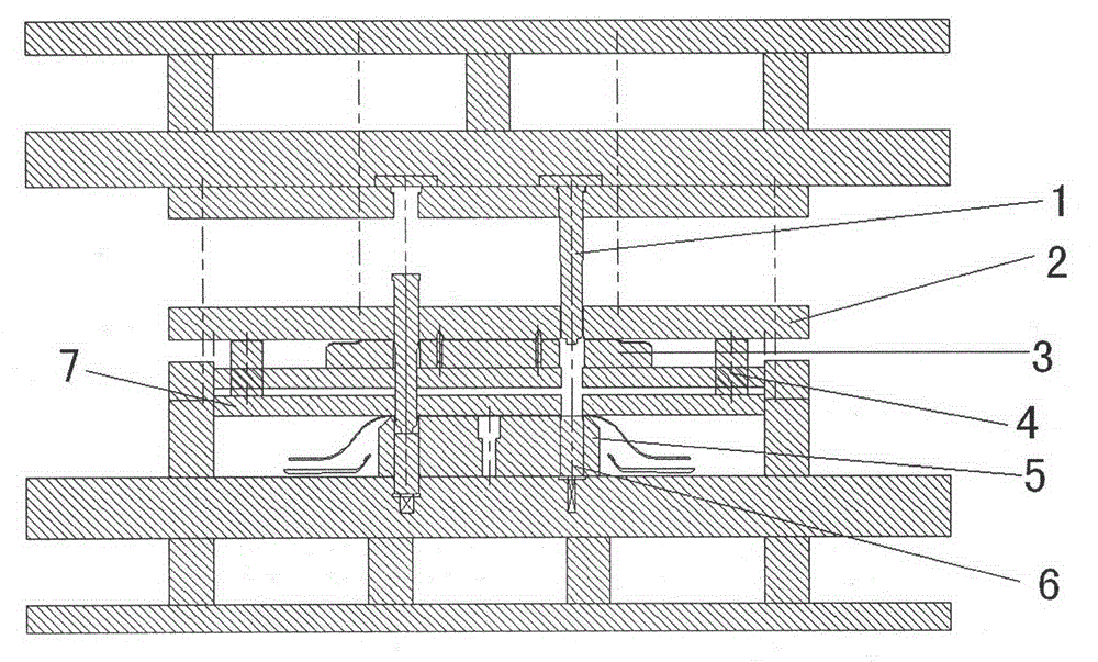
图1是本发明的结构示意图;Fig. 1 is a structural representation of the present invention;
图2是本发明的俯视结构示意图。Fig. 2 is a top view structural schematic diagram of the present invention.
具体实施方式 Detailed ways
为了阐明本发明的技术方案及技术目的,下面结合附图及具体实施方式对本发明做进一步的介绍。In order to clarify the technical scheme and technical purpose of the present invention, the present invention will be further introduced below in conjunction with the accompanying drawings and specific implementation methods.
如图所示,一种同心冲压模具,包括上模座、下模座以及设置在上模座上的冲头1,还包括压料的上压板2、翻孔凹模和下脱料板7,所述翻孔凹模包括上翻孔凹模3和下翻孔凹模5,下翻孔凹模5设置在上翻孔凹模3的正下方,上翻孔凹模3的凹模口轴心和下翻孔凹模5的凹模口轴心在同一轴线上,如图1所示。As shown in the figure, a concentric stamping die includes an upper mold base, a lower mold base, and a punch 1 arranged on the upper mold base, and also includes an upper pressing plate 2 for pressing materials, a punching die and a lower stripper plate 7 , the hole turning die includes an upper turning hole die 3 and a lower turning hole die 5, the lower turning hole die 5 is arranged directly below the upper turning hole die 3, and the die opening of the upper turning hole die 3 The axis and the axis of the die mouth of the downturning die 5 are on the same axis, as shown in Figure 1.
在翻孔凹模上设置好物料位置后,所述上压板2压在上翻孔的物料上。下脱料板7位于上翻孔凹模3设置的下方,压在下翻孔物料上。所述下翻孔凹模5设置在下模座上,位于下脱料板7下方,使上翻孔凹模3和下翻孔凹模5凹模口的轴心在同一竖直直线上。上翻孔凹模3与下脱料板7之间设有一限位板,所述限位板两端各设有一上下两端贯通限位板的限位柱4,所述限位柱4顶端与上压板2连接,其底端与下脱料板7连接,用于控制间隔上下两套模具间的距离。所述下翻孔凹模5内设有翻孔内脱块6,翻孔内脱块6底端设有弹性复位装置。After the position of the material is set on the punching die, the upper pressing plate 2 is pressed on the punching material. The following stripper plate 7 is positioned at the below that the hole-turning die 3 is arranged on, and is pressed on the hole-turning material. Described down turning hole die 5 is arranged on the lower mold base, is positioned at following stripping plate 7 below, makes the axial center of turning up hole die 3 and down turning hole die 5 die openings on the same vertical line. A limit plate is provided between the upper turning die 3 and the lower stripper plate 7, and a limit column 4 with the upper and lower ends of the limit plate is respectively provided at both ends of the limit plate, and the top of the limit column 4 is It is connected with the upper platen 2, and its bottom is connected with the lower stripping plate 7, which is used to control the distance between the upper and lower two sets of moulds. The bottom of the hole-turning die 5 is provided with a turning-off inner block 6, and the bottom end of the turning-back inner block 6 is provided with an elastic reset device.
所述冲头1包括上段冲杆、下段冲杆及顶端刀头,所述下段冲杆直径小于上段冲杆,使得冲头1呈梯形柱状,上段冲杆与下段冲杆之间连接的部位设为斜面。The punch 1 includes an upper section punch, a lower section punch and a top cutter head, and the diameter of the lower section punch is smaller than the upper section punch, so that the punch 1 is trapezoidal columnar, and the connecting position between the upper section punch and the lower section punch is set for the slope.
以上已以较佳实施例公开了本发明,然其并非用以限制本发明,凡采用等同替换或者等效变换方式所获得的技术方案,均落在本发明的保护范围之内。The above has disclosed the present invention with preferred embodiments, but it is not intended to limit the present invention, and all technical solutions obtained by adopting equivalent replacement or equivalent transformation methods fall within the protection scope of the present invention.
Claims (4)
Priority Applications (1)
| Application Number | Priority Date | Filing Date | Title |
|---|---|---|---|
| CN 201110191616 CN102327950B (en) | 2011-07-08 | 2011-07-08 | Concentric stamping die |
Applications Claiming Priority (1)
| Application Number | Priority Date | Filing Date | Title |
|---|---|---|---|
| CN 201110191616 CN102327950B (en) | 2011-07-08 | 2011-07-08 | Concentric stamping die |
Publications (2)
| Publication Number | Publication Date |
|---|---|
| CN102327950A CN102327950A (en) | 2012-01-25 |
| CN102327950B true CN102327950B (en) | 2013-06-12 |
Family
ID=45480062
Family Applications (1)
| Application Number | Title | Priority Date | Filing Date |
|---|---|---|---|
| CN 201110191616 Expired - Fee Related CN102327950B (en) | 2011-07-08 | 2011-07-08 | Concentric stamping die |
Country Status (1)
| Country | Link |
|---|---|
| CN (1) | CN102327950B (en) |
Families Citing this family (2)
| Publication number | Priority date | Publication date | Assignee | Title |
|---|---|---|---|---|
| CN102652974A (en) * | 2012-05-09 | 2012-09-05 | 昆山飞宇精密模具有限公司 | Multi-process composite die for drawing forming |
| CN104859353A (en) * | 2015-05-22 | 2015-08-26 | 苏州飞宇精密科技股份有限公司 | Low-temperature thermal shroud embossing die |
Citations (3)
| Publication number | Priority date | Publication date | Assignee | Title |
|---|---|---|---|---|
| CN2640653Y (en) * | 2003-08-22 | 2004-09-15 | 中国重型汽车集团有限公司 | Mould for working multiple products |
| CN101767153A (en) * | 2010-01-29 | 2010-07-07 | 华中科技大学 | Composite forming die |
| CN202129344U (en) * | 2011-07-08 | 2012-02-01 | 昆山飞宇精密模具有限公司 | Concentric punching die |
Family Cites Families (2)
| Publication number | Priority date | Publication date | Assignee | Title |
|---|---|---|---|---|
| SU1204299A1 (en) * | 1983-07-08 | 1986-01-15 | Всесоюзный Научно-Исследовательский Технологический Институт Приборостроения Московского Научно-Производственного Объединения "Темп" | Die for punching holes |
| JPH10166076A (en) * | 1996-12-03 | 1998-06-23 | Matsushita Electric Ind Co Ltd | Press die for punching |
-
2011
- 2011-07-08 CN CN 201110191616 patent/CN102327950B/en not_active Expired - Fee Related
Patent Citations (3)
| Publication number | Priority date | Publication date | Assignee | Title |
|---|---|---|---|---|
| CN2640653Y (en) * | 2003-08-22 | 2004-09-15 | 中国重型汽车集团有限公司 | Mould for working multiple products |
| CN101767153A (en) * | 2010-01-29 | 2010-07-07 | 华中科技大学 | Composite forming die |
| CN202129344U (en) * | 2011-07-08 | 2012-02-01 | 昆山飞宇精密模具有限公司 | Concentric punching die |
Non-Patent Citations (1)
| Title |
|---|
| JP特开平10-166076A 1998.06.23 |
Also Published As
| Publication number | Publication date |
|---|---|
| CN102327950A (en) | 2012-01-25 |
Similar Documents
| Publication | Publication Date | Title |
|---|---|---|
| CN203044667U (en) | Upside-down type composite die | |
| CN203470617U (en) | Flat hole stamping mould | |
| CN202162259U (en) | Stamping die provided with concentric hole | |
| CN203209540U (en) | Clutch friction plate forming mold | |
| CN102327950B (en) | Concentric stamping die | |
| CN203018592U (en) | Bulging and flanging composite die for machining valve rocker | |
| CN203044637U (en) | Forging precision thermal punching mold | |
| CN203751113U (en) | Short convex mold plate material punching die | |
| CN202129344U (en) | Concentric punching die | |
| CN206169049U (en) | Stamping die is connected to an awl section of thick bamboo | |
| CN103464599A (en) | Punching die structure for stamping | |
| CN102962345A (en) | Punching, blanking and stretching die for take-or-pay table | |
| CN202824374U (en) | Knuckle support stamping device with error proof function | |
| CN202845597U (en) | Bending punching die | |
| CN103537548A (en) | Stamping die provided with guide pillar | |
| CN202336522U (en) | Vehicle body floor blanking die limiting device | |
| CN202146947U (en) | Composite die for molding and punching | |
| CN106238564A (en) | Automobile tractor bracket piercing die | |
| CN207787503U (en) | A DX3 barrel punching and flanging die | |
| CN206046817U (en) | A small punching machine for integrated braiding | |
| CN102327975A (en) | Molding and punching composite die | |
| CN102962323A (en) | Punching die of take-or-pay table | |
| CN203197100U (en) | Novel forming die | |
| CN203155828U (en) | Novel mold | |
| CN102950209A (en) | Antenna production progressive die |
Legal Events
| Date | Code | Title | Description |
|---|---|---|---|
| C06 | Publication | ||
| PB01 | Publication | ||
| C10 | Entry into substantive examination | ||
| SE01 | Entry into force of request for substantive examination | ||
| C53 | Correction of patent of invention or patent application | ||
| CB02 | Change of applicant information |
Address after: 215300, Sifang Road, 28 North Town, Yushan Town, Jiangsu, Kunshan Applicant after: SUZHOU FEIYU PRECISION TECHNOLOGY Co.,Ltd. Address before: 215300, Sifang Road, 28 North Town, Yushan Town, Jiangsu, Kunshan Applicant before: Kunshan Feiyu Precision Mold Co.,Ltd. |
|
| COR | Change of bibliographic data |
Free format text: CORRECT: APPLICANT; FROM: KUNSHAN FEIYU PRECISION TOOL CO., LTD. TO: SUZHOU FEIYU PRECISION TECHNOLOGY CO., LTD. |
|
| C14 | Grant of patent or utility model | ||
| GR01 | Patent grant | ||
| CF01 | Termination of patent right due to non-payment of annual fee |
Granted publication date: 20130612 |
|
| CF01 | Termination of patent right due to non-payment of annual fee |